Jump to content

Keith Black

NRG Member
  • Posts

    4,269
  • Joined

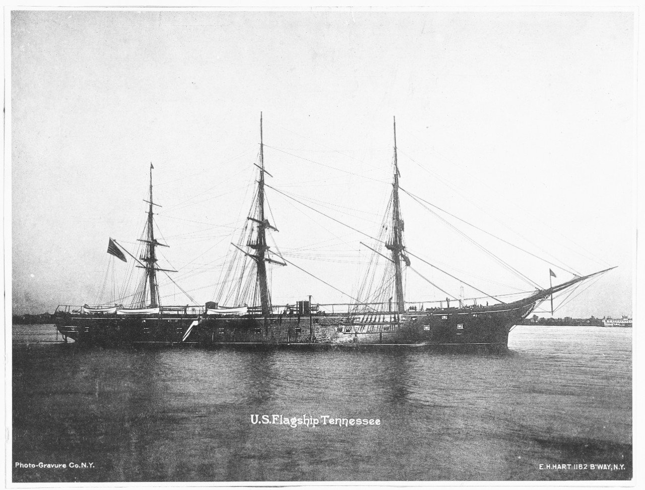
  • Last visited

Everything posted by Keith Black

  1. The signal cannon was another story. I've always thought the first one I made looked more like a field piece than a signal cannon. On to signal cannon 2.0, 1.0 is on the left
  2. In getting back to the deck guns I went over the gatling guns, signal cannon, and the one, eight inch Dahlgren gun I've completed. I've decided I can't do any better on the gatling guns. These are the 4.0 model and as poor as they are this is as good as it gets. They kinda look like gatling guns a couple of feet away?
  3. I myself have found that while waiting for genius I've gotten more poop than pop...........fiberglass resin also works very well as a plaster sealer.
  4. Once I had the three cowl vents completed I made a mockup of the deck where I could place the vents on the deck with the first try. I've included a couple of photos of one of the original model's cowl vents to show how far out of scale the original deck elements were.
  5. The last deck elements I needed to make before completing the deck guns were the three cowl vents that go forward of the fore funnel. I'll show how I make these in hopes that in may help someone else who also has limited tools at their disposal. 1) Drill the opening for is to be the head and then turn using drill motor and jewelers file. 2) Once the head is turned cut it at a 45 degree angle and cut the tube at a 45 degree angle. 3) Mate the two with a generous supply of glue. (I wasn't able to figure a means of pinning the head and tube) 4) Because the head is so much larger than the tube, there is a lot of wood that needs to be removed with sandpaper and file to shape the two pieces.
  6. Wikipedia states this photograph of the Tennessee was taken at the Brooklyn Navy Yard in 1875. Is that date/could that date be correct? That date doesn't make sense to me but then....... Would it make more sense if this were taken sometime during the work period between Madawaska and Tennessee? The Hatton and Hart photographs don't support the four funnels to the starboard side between the stacks nor positioning of the two 100 pound Parrott rifles rear of the mizzen. Also the flying bridge seems unfinished and the skylight that provided light to the helm area is to port laying on it's side. Second question regarding where the chains are attached. In the 1875 dated photo the chains are attached to the hull above the second deck ports. In another silhouette photo (date unknown) the chains are attached below the ports. Thoughts on when this change was made? Third and last, I calculate that the distance between center lines of the two stacks is 73' 3". In the drawing a distance of 106 feet is given for end of boilers to end of boilers (coal bins are not included in the 106 feet. Would someone please verify that distance......thank you.
  7. I felt like I had really turned the corner when I was able to start making the deck elements. My rules have been, that if I couldn't make it look close to what an element actually looked like, don't make it. Don't make an element if you can't verify it was actually part of the ship (don't make up history, accurately portray history to the best of your ability) Don't make an element if it's going to look cheesy, better to not make it at all. To accomplish making pieces I've had to rely on pretty simple tools. Turnings are done with a drill motor and jewelry files, cuttings done with jeweler's saw and x-acto knives. If I had another 30 to 40 years of modeling left to me, I'd invest in some real tools. I'm pretty sure this is going to be my one trick pony but I'd love to scratch build a 1880's steam driven yacht and and, yeah, them too. Steam driven vessels fascinate the dickens out of me. Building at one tenth of an inch equals a foot is easy math but it sure test my abilities. The telegraph engine controls is pretty much at my limit. February of 2017 found me doubting that I'd every be able to do work this small.
  8. Making one is easy, making two that are exactly alike is the tricky part.

  9. The Tennessee was 355 feet in length and 45 feet two inches at beam. The model hull is 30 inches in length and 5.5 inches at beam. The shortness of the hull is most noticeable at the stern. I've had to crowd a number of elements at the stern and that disturbs me but that's having to play the hand I was dealt. After getting the stern area hollowed out as needed I turned my attention the the ports. Once again the shortness of the hull made it necessary to cut only ten ports on the second deck level verses eleven as was on the Tennessee. I had to plug and fill in the top deck ports of the original model as they were in no way positioned correctly to allow for the chain rails. On the original model the ports had glued paper as covers. After cutting the ports square I let in wood port covers a fraction to create shadow lines. Once the ports were done I then added the chain rails, added the piece of wood just below the top of the bulkhead that runs from each side of the bow completely a round the model, anchor guards and anchors. Making the starboard and port galleries proved to be the most complicated part of the hull. The trick was not so much in the making of one, it was making two that looked alike! If I've not given the proper name or term to an element, PLEASE provide the correct name/term where I'll know, thank you. I then started work on the inside bulkhead filling and sanding the vertical pieces of wood from the original model (I think the vertical pieces were bamboo) running horizontal strips for ports and the pin rails. I'm not real pleased with the pins put once they're covered with looped line I don't think one will see very much of them. I still need to cut four ports at the stern, two each both starboard and port side of the eagle.
  10. Before I get too far a field I need to take a moment to thank those in the Nautical/Naval History side of this site. If not for member Talos I wouldn't have the majority of the H&H photos I have to reference and has also provided other photographs and drawing. Mark Taylor, Roger, Druxey, Canute, Steven, Dave and others have provided ideas, support and encouragement. If they hadn't been there for me, I wouldn't be here. In some of my photographs you see a little stick figure sailor, that's "Bob". I got tired of constantly trying to place my machinist ruler on the deck to gauge how high I needed to make an element. So I made Bob to represent a man 5'11'' in height (he's just shy of six tenths of an inch tall. Bob isn't going to be part of the final build but there maybe a Bob 2.0
  11. As this is a solid wood hull my first step in correcting the model was to hollow out the stern section where I could get the ship's wheel and binnacles under the upper stern deck. The original model had the ships wheel in the open forward of the mizzen. H&H photos of the ships wheel can be seen in the previous post.
  12. The Hatton and Hart photographs were/are my primary source for trying to create as much model authenticity as possible. Sometimes I have to assume, which I hate. Example being, on the upper stern deck a partial funnel profile can be seen behind and to the port side of a binnacle. (I may as well jump on this grenade while I'm here. This binnacle appears to be about five and a half feet tall, a foot and a half above the standard four feet. Access to viewing the compass is aided by a two step ladder propped up against it seen in the first of the four H&H photos.. I'm guessing the reason for the extra height is where the compass is above the railing and other metal objects. Please jump in with comments should you have other thoughts) All other photographs from the starboard point of view are and blurred and of no use determining if a starboard funnel is actually there. I chose one to be there due to ship designers seemingly love of and necessity for symmetry.
  13. Druxey It's territory I have the upmost respect for. For whatever reason I seem to be having a hard time coming up with a one word description of how I feel about the scratch build section of this site. Scared may not be the correct word but it's somewhere in that vicinity. Steven, thank you.
  14. Thank you Roger, Talos. I'm going to blue tape where and how I think the ports are located. I'll black out what I made for the officers latrines and come back with a photo and you can correct me if needed. I thought the top split cover was an element unto it's self and not that of the top part of a hatch cover. Do you guys think I need to move this discussion to the scratch build section? I'm somewhat loath to do so as I'm not sure this project is worthy of what I consider pretty sacred territory. Neither do I want to clutter up this area of discussion if this isn't the proper place??.........Keith
  15. Thank you Talos, I've thought of you many times as I poured over the link to images of the Tennessee you provided. So you're thought is that the four rectangles (eagle in the middle of the four) are all gun ports? I could see that being the case for the top two but the bottom two? Wouldn't that mean they'ed be in the middle of and taking space away from the officers quarters? Also there's the color difference between covers of the top two and bottom two, plus the top two covers seem to stand proud from the hull where as the bottom two covers seem to be flush. I for sure don't know but I'll happily cut and make them all gun ports if that's your verdict. I just wanted to make sure before taking the knife to the hull. Thank you again..........Keith
  16. I've lightened but I don't have photoshop capabilities.
  17. Thank you for the welcome back and kind words, it means more than you'll ever know. This is supposed to be the stern of the Tennessee. Anyone know what the element is directly next to the eagle's port side wing tip? Bath? The two elements below the eagle in line with the officer's latrines above? Flags? Thank you........Keith
  18. First and foremost, to any that I offended during my first visit, my most sincere apologies! I came here loaded with an abundance of ignorance and I didn't try to hide it. Approximately three weeks after my original posting on January 14th, 2017 I had a stroke. I lost 30% of the vision in my right eye and my left hand was completely paralyzed. In fact, my stroke occurred while I was working on the Tennessee lifeboats. Through the grace of God and dedicated physical therapist, I recovered the full use of my left hand. The vision in my right eye will remain at a negative 30% the rest of my life. During recovery I vowed that should I regain the use of left hand, I would set about to make the Tennessee as right as I possibly could given the short comings of the hull, 10 inches too short and an inch to wide at the beam. For a year I tried to learn as much about the Tennessee as I could pouring over the Hatton and Hart photographs of scenes onboard the Tennessee, seeking out photographs other wood hull screw frigates, models, books and picture postcards. January of this year I stripped the model down to the bare hull and started over. This has been my therapy and what's kept my juices flowing Coming back two years later is just as awe inspiring as was my first time here. What you folks can do, the magic you fingers work leaves me in utter amazement! I post a couple of pictures of my efforts to date, not so much as "look what I've done" but to complete a circle, to apologize, and to thank each and everyone here whom it was my pleasure to meet.
  19. A huge "thank you" to each who provided information, pictures, and links. That's why I came, mission completed and successful. If someone would remove the "Steam frigate USS Tennessee" topic from the scratch build section I'd appreciate it. I'll not insult the fantastic, unbelievable work done by the members of this guild with a restoration log of my misshapen halfling. That's not hurt feelings speaking, that's the respect I have for your abilities as a community............Keith
  20. Hey Roger, thanks a ton for the heads up on the book! I've bookmarked it and plan on ordering shortly. I agree with your assessment of the hull, another foot would help tremendously. Unless you've seen something I haven't, the basic hull and funnel configuration of the model matches only that of the Tennessee. At least that's my thought having researched all the US steam frigates and matching them against the model. Believe me when I say I tried very hard to find another one that made more sense. I've owned this model for slightly over four years and I did a lot of looking before I started the restoration process in ernest. Another fly in the ointment, the Tennessee underwent several refits. Do photographs exist that were taken after each refit? I hope the answer (or least some of the answer) is provided in Vol 1. Thank you again for the info on the book..........KB
×
×
  • Create New...