
Keith Black
-
Posts
6,725 -
Joined
-
Last visited
Content Type
Profiles
Forums
Gallery
Events
Everything posted by Keith Black
-
Marty, welcome to MSW. Glad to have you aboard.
-
Ross, welcome to MSW. Nice looking Beagle. Glad to have you aboard.
-
Bruce, welcome to MSW. Glad to have you aboard.
-
Lester, my apologies for hijacking your log.
-
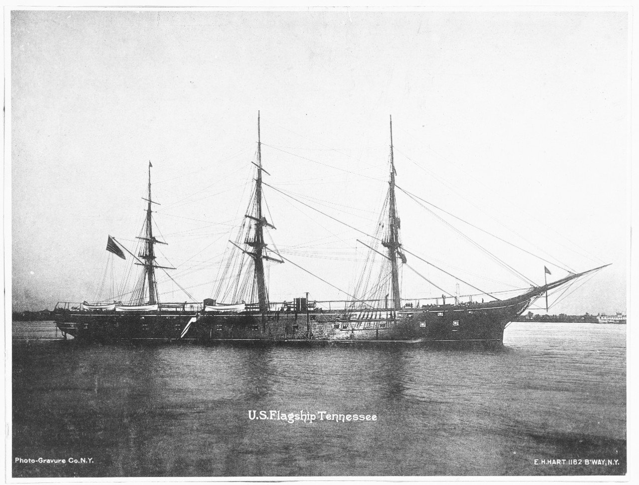
Steven, thank you for asking. Short answer is no. After posting the above the other day I put the Amelia on the worktable and thought to myself, I need to finish this project. So, after two and a half years of neglect I'm on a mission to finish her. I've sailed into the dreaded doldrums with the Tennessee so a change maybe just the ticket. A ragging debate is going on inside my head as I consider sails or no. I feel somewhat obligated to add sails as that is the way the model was finished. The original sails are rotten so new sails would have to be made. I'm not a big fan of sails as I think they hide a lot of the modeler's work. I would like to upgrade the rigging a tad with blocks (single only) but blocks weren't original to the model so that inner debate continues. Also, eyelets were not used, lines was simply tied off around nail heads. if I add blocks I would want to add eyelets as well. I welcome all thoughts and suggestions.........please.
-
Juan, welcome to MSW. Glad to have you aboard.
-
 Me too, Ed.
 -
Lester, welcome to MSW. Glad to have you aboard. You can view my restoration efforts on the same type of decorator model in the log below. Best of luck to you.
-
That's awesome stuff, Simon. Way beyond the abilities of my old brain.
-
Ross, welcome to MSW. Glad to have you aboard.
-
SJI, welcome to MSW. Glad to have you aboard.
-
Grant, I'm right there with you. I didn't discover Glen's latest till yesterday afternoon. I've got a old cowbell we need to tie around his MSW profile to help keep tabs on his activities.
- 134 replies
-
- 5
-

-

-
- Captain Kidd
- bottle
- (and 3 more)
-
Phil, welcome to MSW. Glad to have you aboard.
-
Pietro, welcome to MSW. Glad to have you aboard.
-
Thomas, welcome to MSW. Glad to have you aboard.
-
Apology? Not hardly. Like yourself, we're all scrambling to complete task/projects before winter sets in. We'll be here when you're able to get back to the Cairo.
- 113 replies
-
- 5
-
-
- Cairo
- BlueJacket Shipcrafters
- (and 1 more)
-
New to MSbuilding, new to MSW. Hi!
Keith Black replied to jonstable's topic in New member Introductions
Jon, welcome to MSW. Very nice Polaris. Glad to have you aboard.
