
JpR62
-
Posts
699 -
Joined
-
Last visited
Content Type
Profiles
Forums
Gallery
Events
Everything posted by JpR62
-
 Thank you Derek for your answer and thank you to all the 'Likes'. It is my first work done with the MF70. The work is not necessarily faster but on the other hand what precision. For the diameter of the deck treenails, so I will start with a 1 mm drill bit.
 -
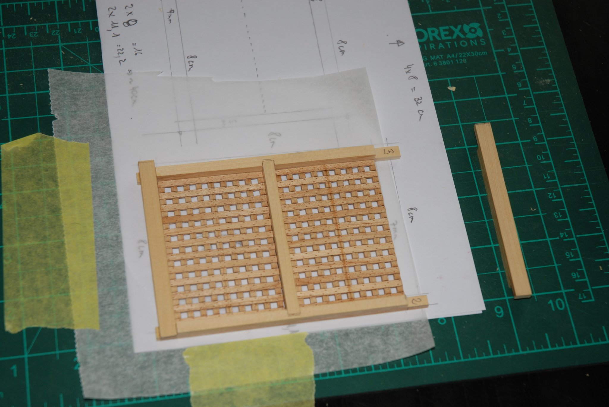
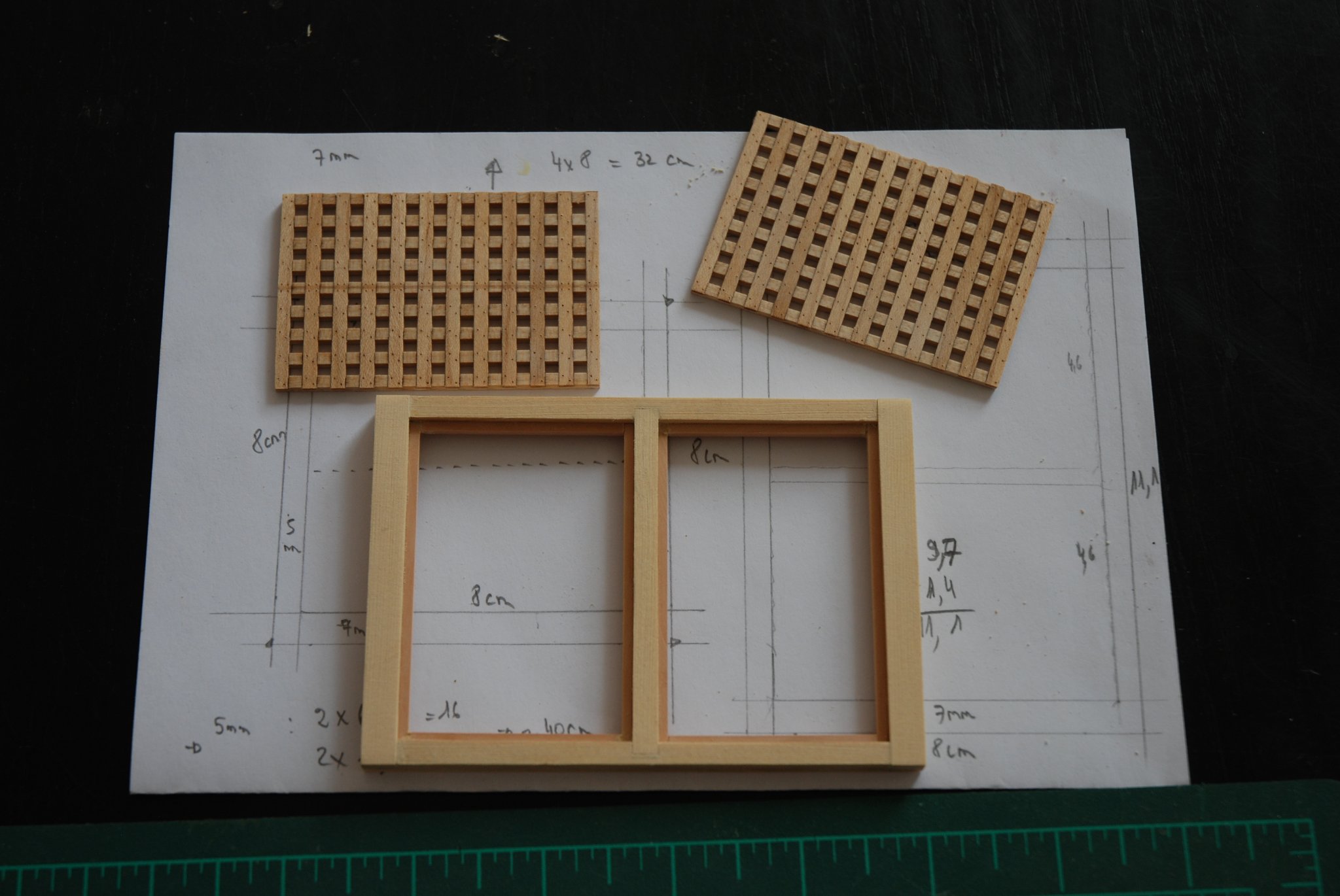
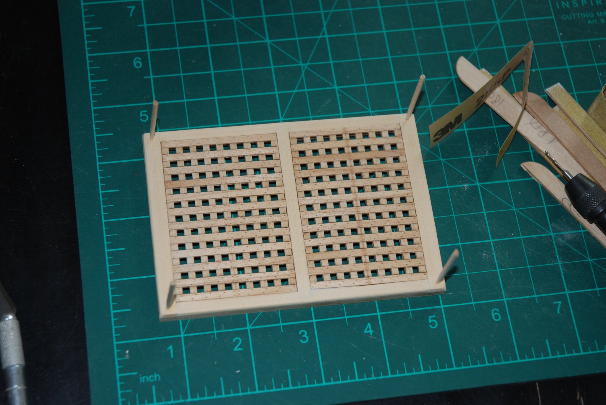
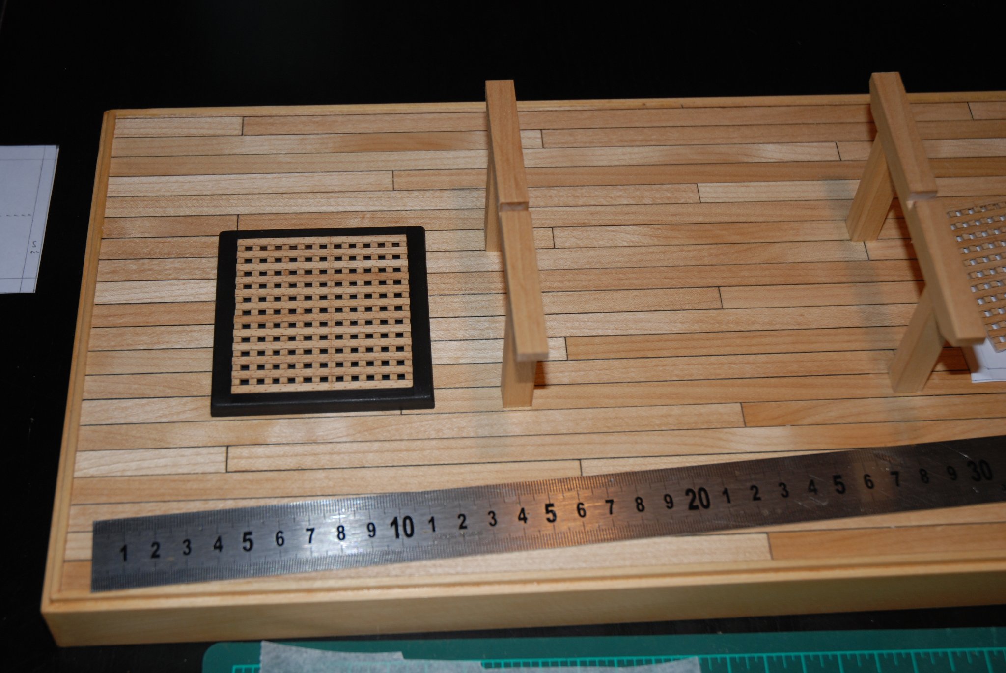
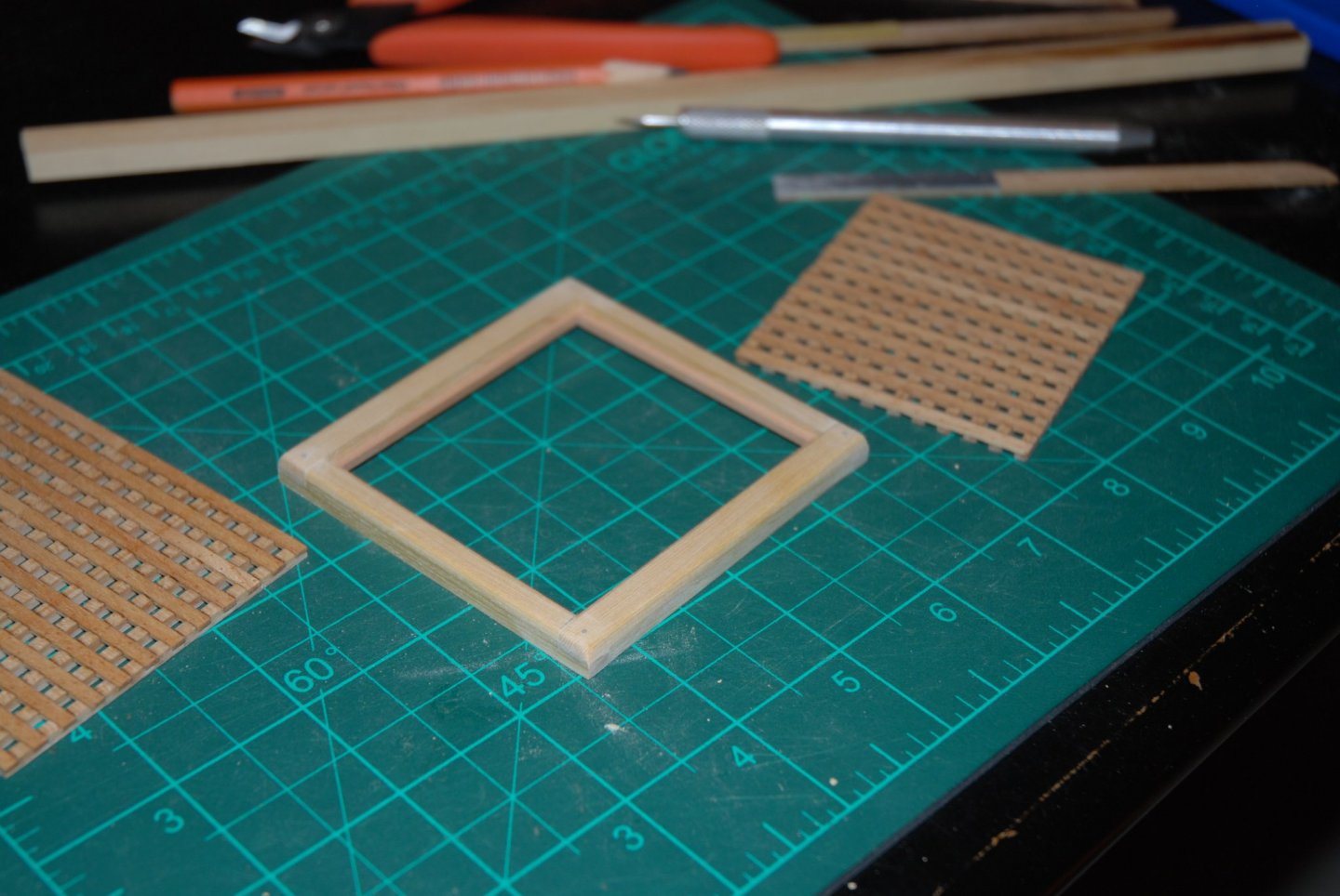
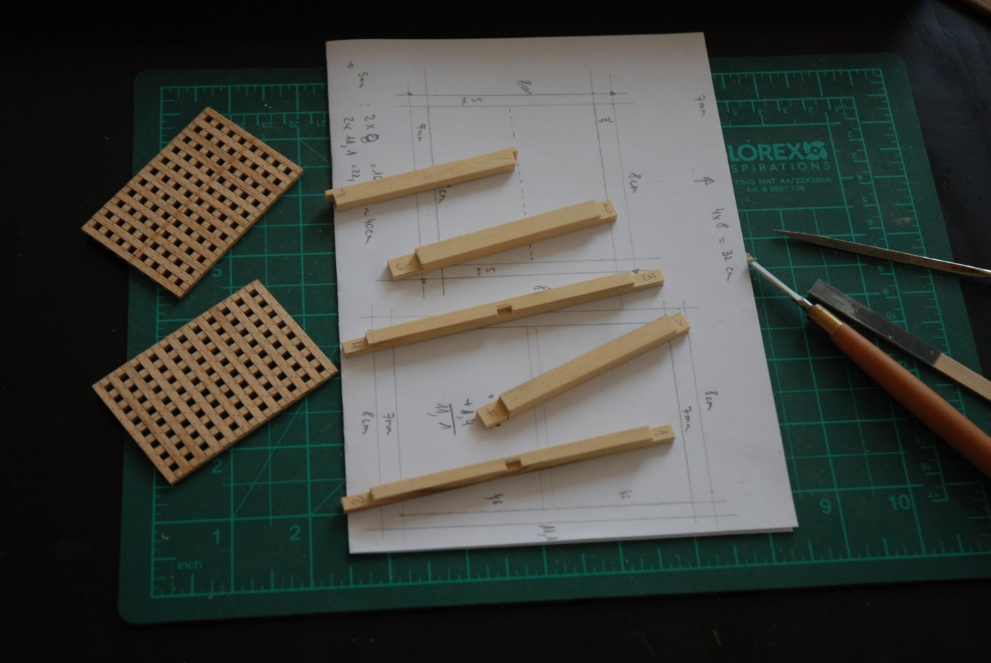
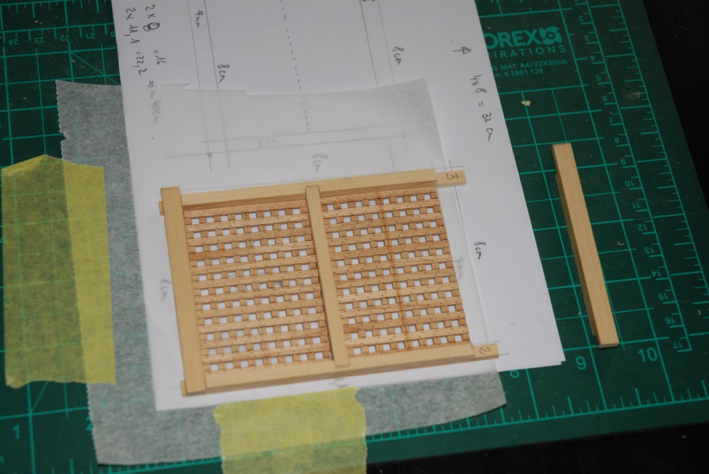
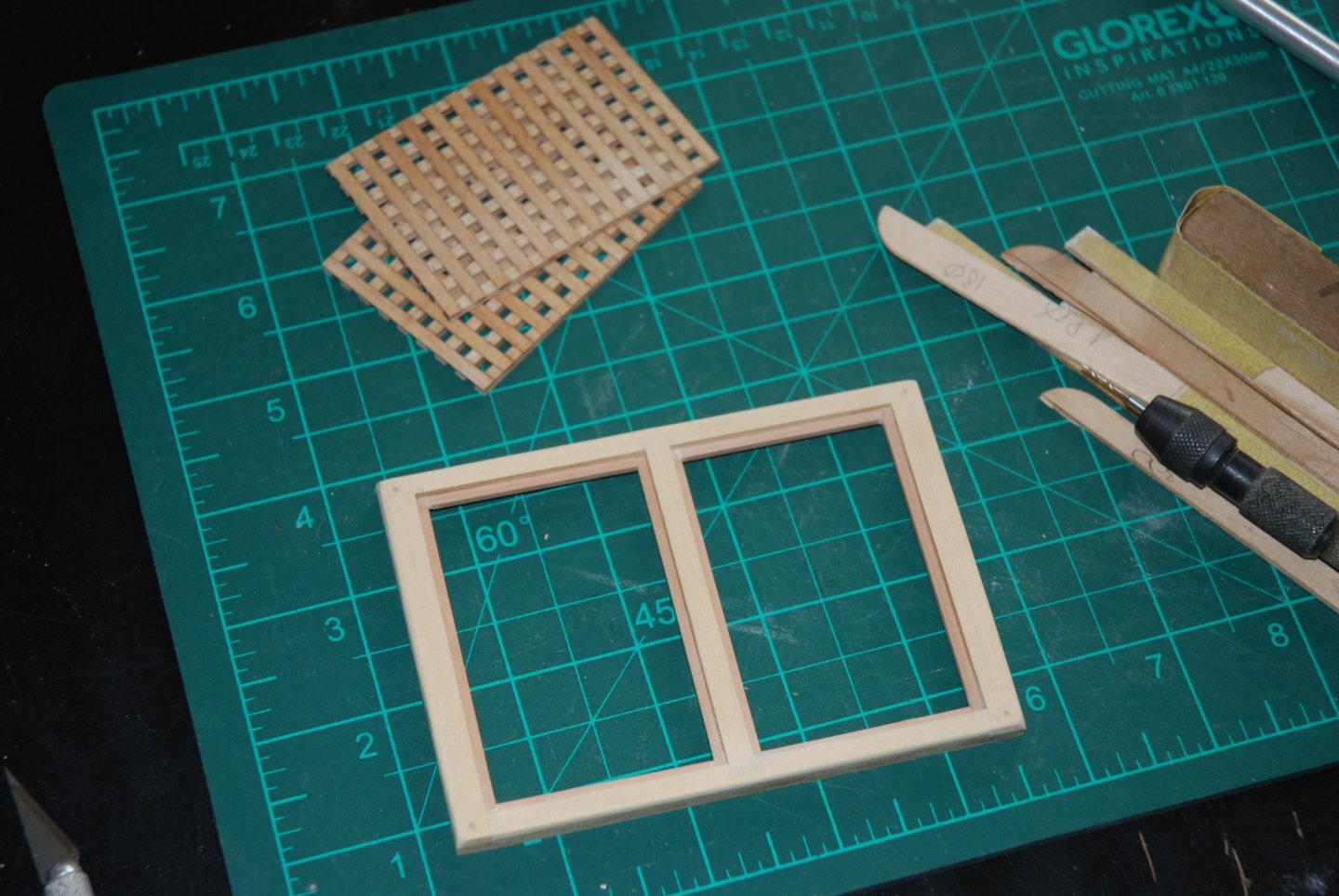
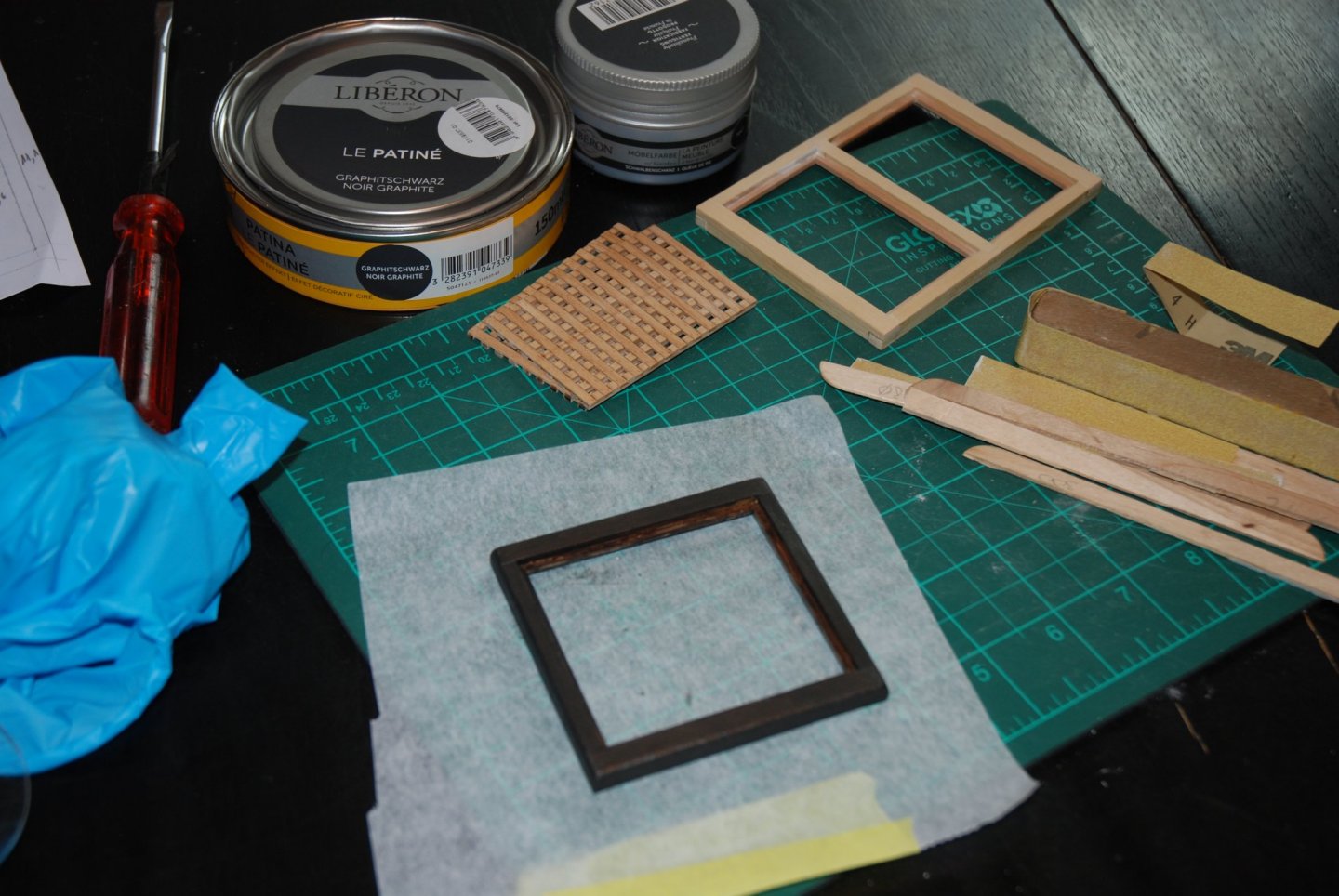
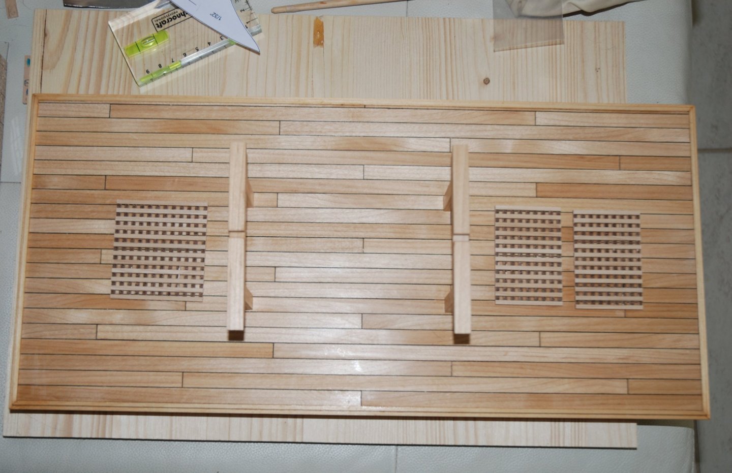
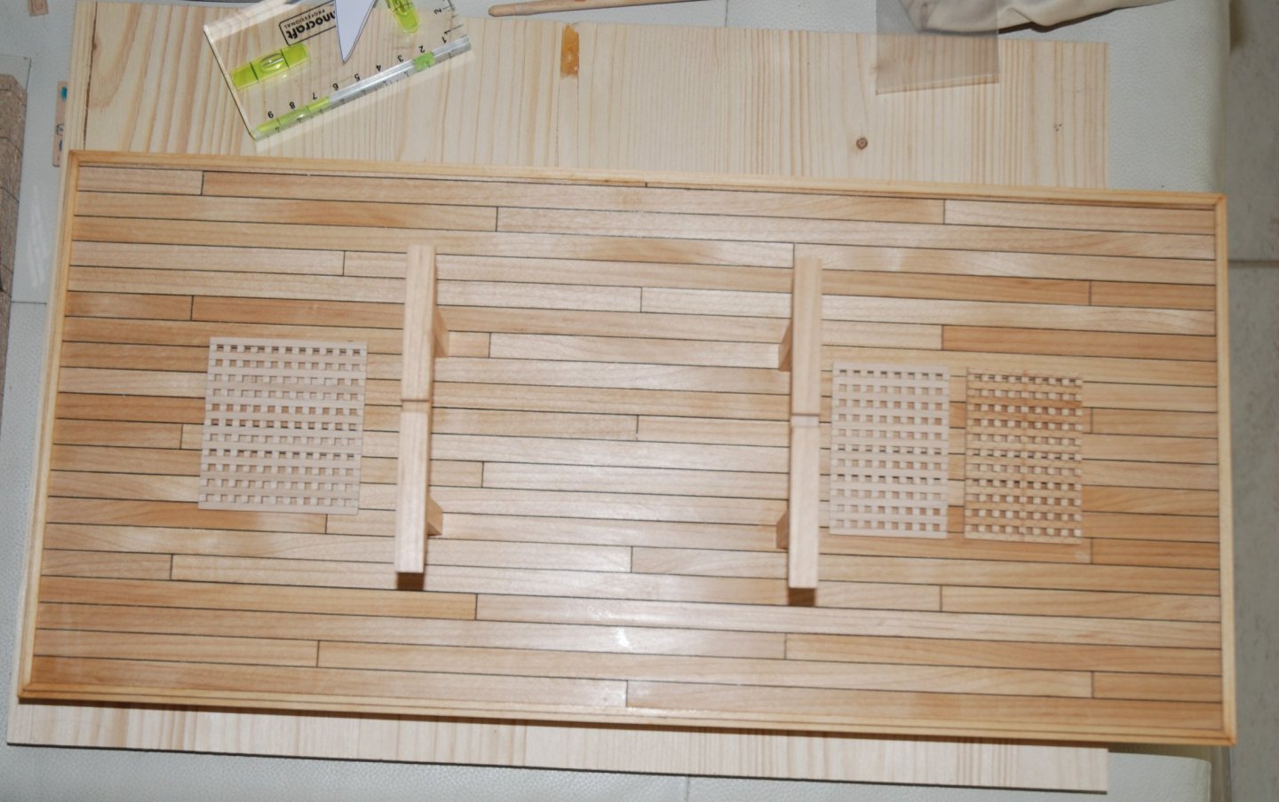
Thank you to all the 'Likes'. The work on the gratings is almost finished. I still have to glue them on the deck. For the hatch, I used strips of wood cut with my Byrnes table saw from a sheet of 1/4" thick milled Yellow Alaskan Cedar sheet. I really like this wood because it allows for precise cuts and makes for clean angles. The coamings have lap joints on the corners. The first coaming is done and ready to receive its grating. First, all coamings are prepared. The lap joints are made with my new tool, a Proxxon MF70 micro milling machine and I must admit that it is very precise. A first blank assembly is carried out. Once the assembly is completed, the excess lengths are sanded down. The edges are rounded and the treenails simulated with toothpicks. For the coloring, I tested a new product from Liberon. It is a casein furniture paint. A finish with a tinted wax, also from Liberon, is finally applied with a soft cloth. A sheet of black paper will be glued under the hatch. I am more and more hesitant to treenail the deck. Does anyone have any idea what size drill bit to use o simulate realistically the treenails at a scale of 1:24 ?


-
Glad to be able to follow this new project. The work done on the New Bedford Whaleboat was outstanding and I am looking forward to the start of this Schooner.
-
Very nice planking work. The result is magnificent !
-
A nice step forward with all these futtocks in place. What finesse. On the way to a new little beauty!
- 433 replies
-
- 5
-

-
- open boat
- small boat
- (and 1 more)
-
Beautiful model. A real pleasure to have been able to follow all the superb work done on this whaleboat.
- 104 replies
-
- 3
-

-
-
- model shipways
- new bedford whaleboat
- (and 1 more)
-
Wonderful work! I really appreciate the choice of colors and their harmony. The technique is also mastered with brilliance.
- 79 replies
-
- 2
-
-
- Fifie
- Victory Models
- (and 1 more)
-
Wonderful work! It's always so clean and precise!
- 607 replies
-
- 2
-
-
- winchelsea
- Syren Ship Model Company
- (and 1 more)
-
Wonderful work as always ! And again a lot of information that will help the next modelers 😀
- 778 replies
-
- 2
-
-
- cheerful
- Syren Ship Model Company
- (and 1 more)
-
HM Cutter Cheerful 1806 by JpR62 - 1:48 scale
JpR62 replied to JpR62's topic in - Build logs for subjects built 1801 - 1850
Thank you Glenn for the answers and thank you to all the 'Likes'. Glenn, I will reread your log carefully to study the interaction between the different parts (fashion pieces, square tuck, counter and planking). -
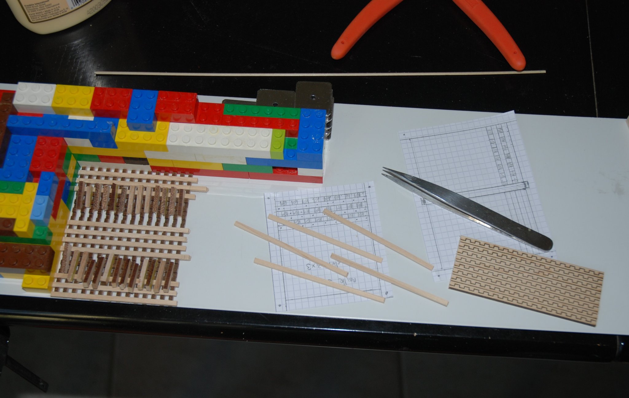
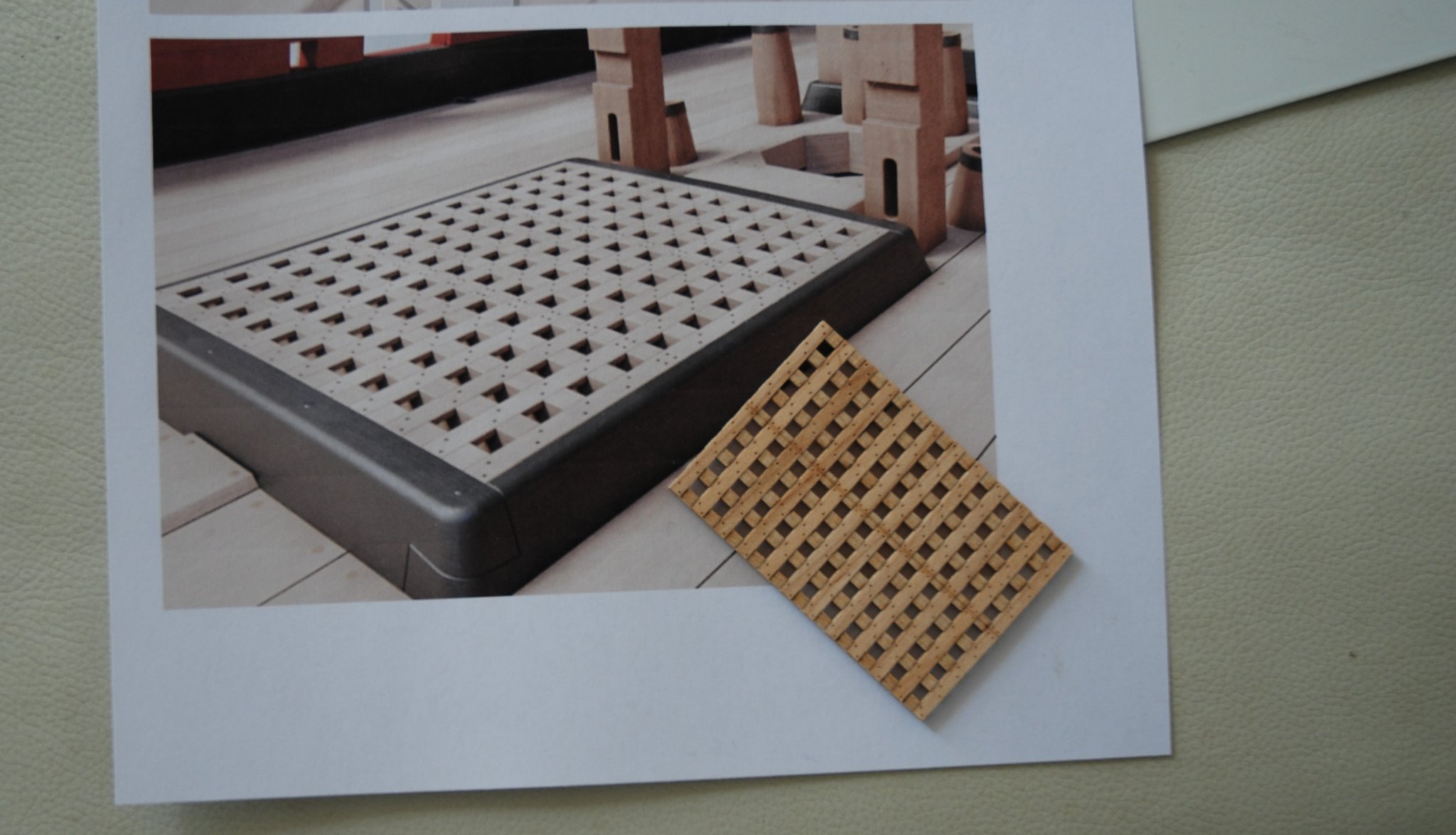
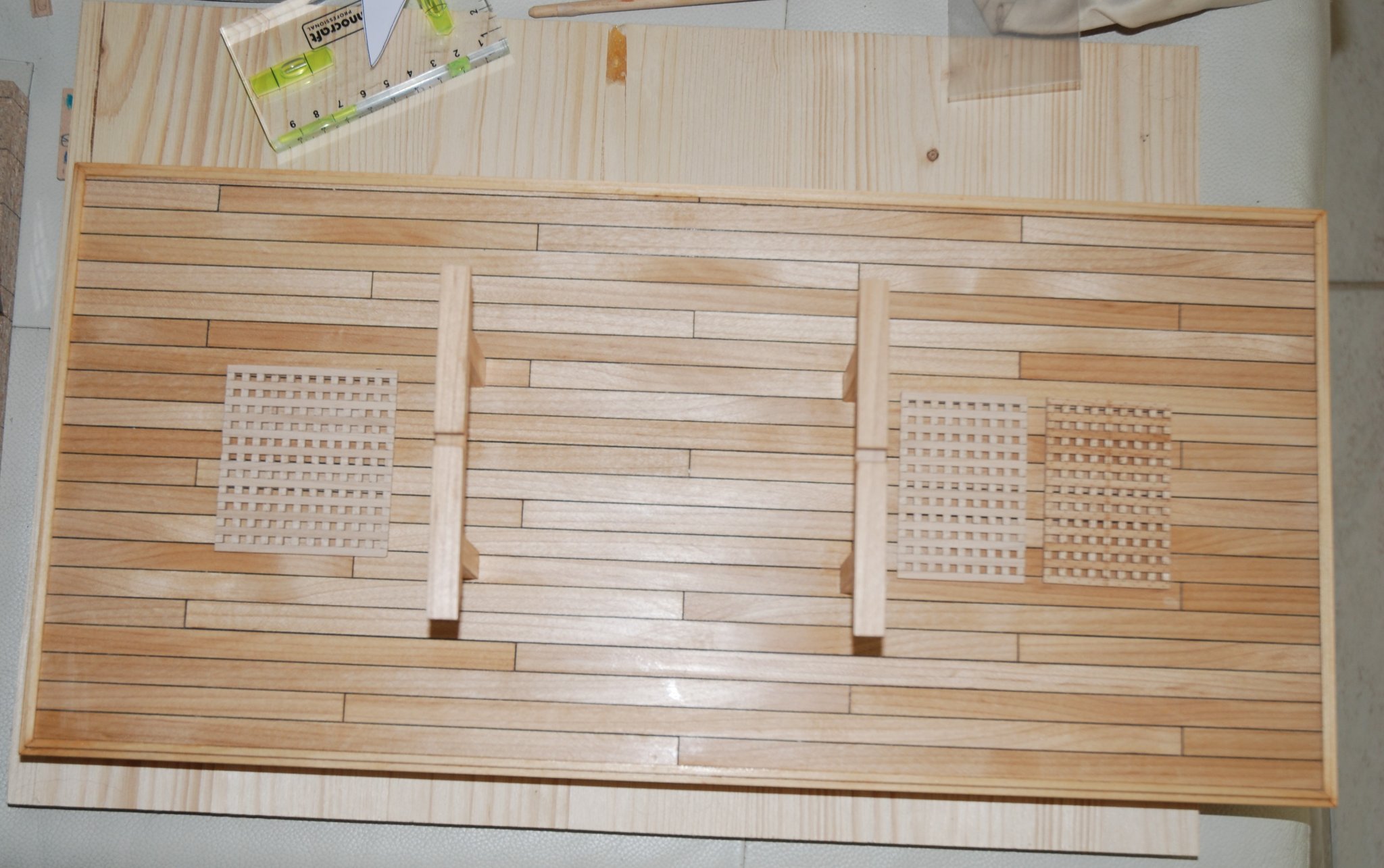
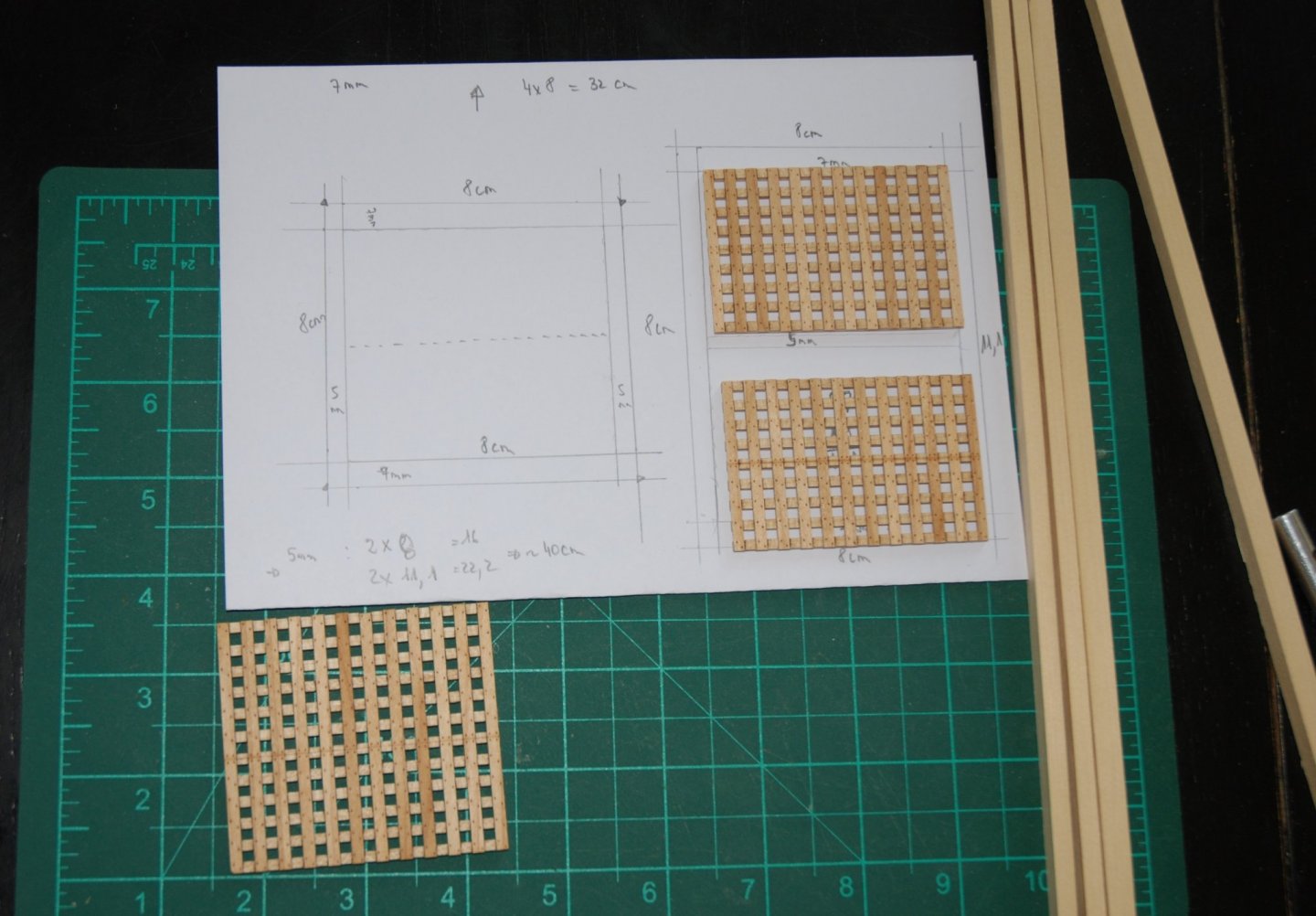
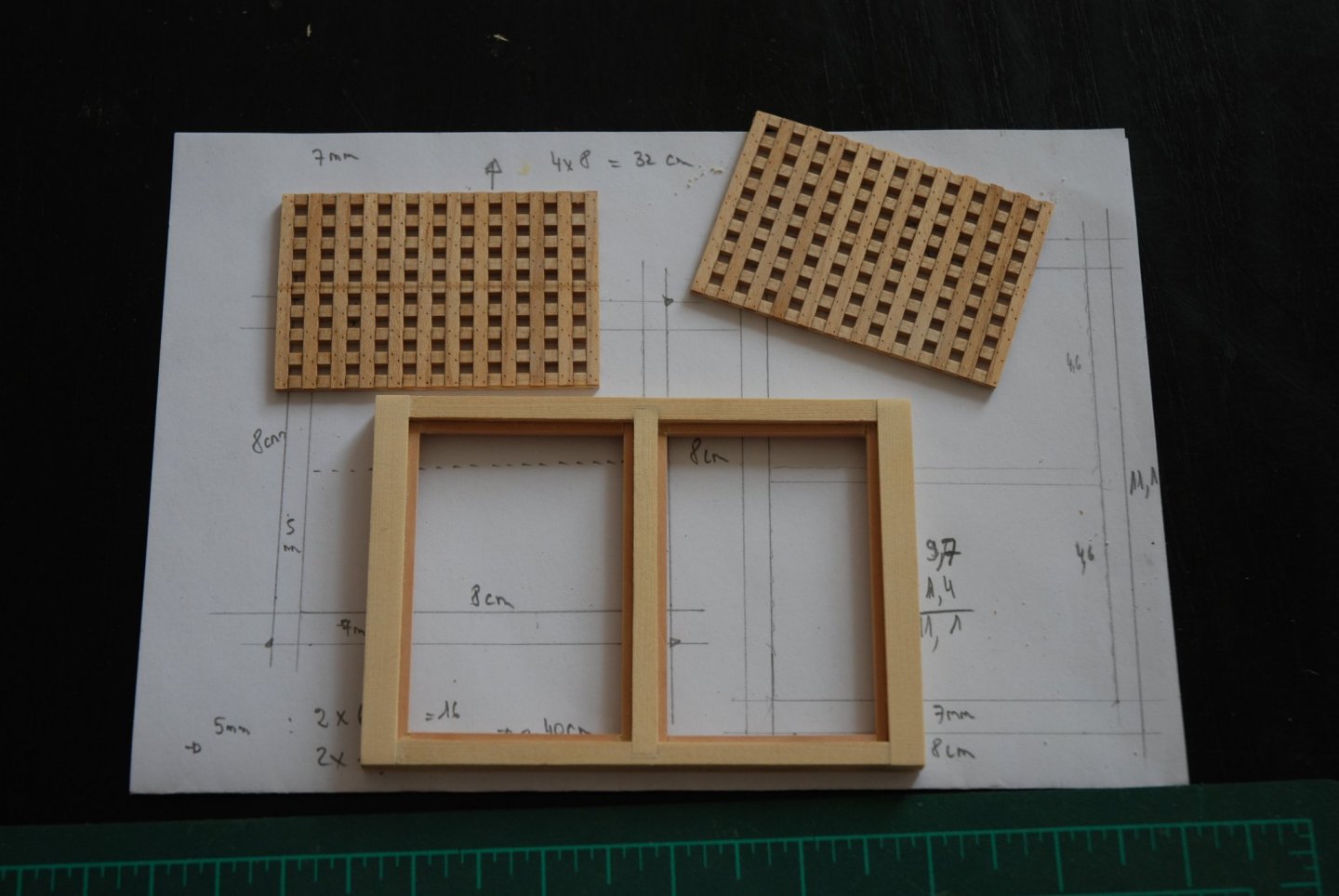
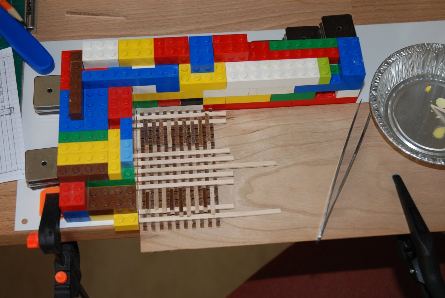
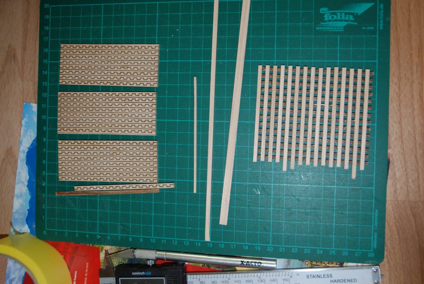
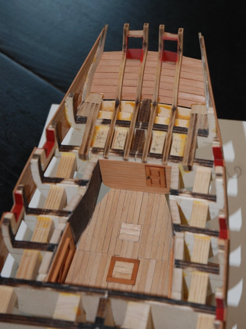
I had put my project on the longboat on hold because I have a pretty good idea of its future presentation which will be inspired by Steve's wonderful work. I was looking for gratings that could match the 1:24 scale. Finally, I found what I was looking for at CAF who provides gratings at different scales. The largest one allows for a 3 mm spacing. So I cut 3 mm wide strips with my Byrnes table saw. The assembly is then a breeze. The three elements are then cut to size and sanded. At this scale, we can afford quite precise details. Having the beautiful 3D photos of Swan class virtual 3D purchased from Admiralty Models, I was able to have a precise documentation. These virtual views are absolutely beautiful and the price is really modest considering the quality and quantity of details on this class of ship. I allowed myself to photograph one of my gratings next to one of the detail photos of the Swan Class virtual 3D. You can only admire the quality of these photos... And there are hundreds of them detailing all the elements of the ship! The nailing session will still be long...


-
HM Cutter Cheerful 1806 by JpR62 - 1:48 scale
JpR62 replied to JpR62's topic in - Build logs for subjects built 1801 - 1850
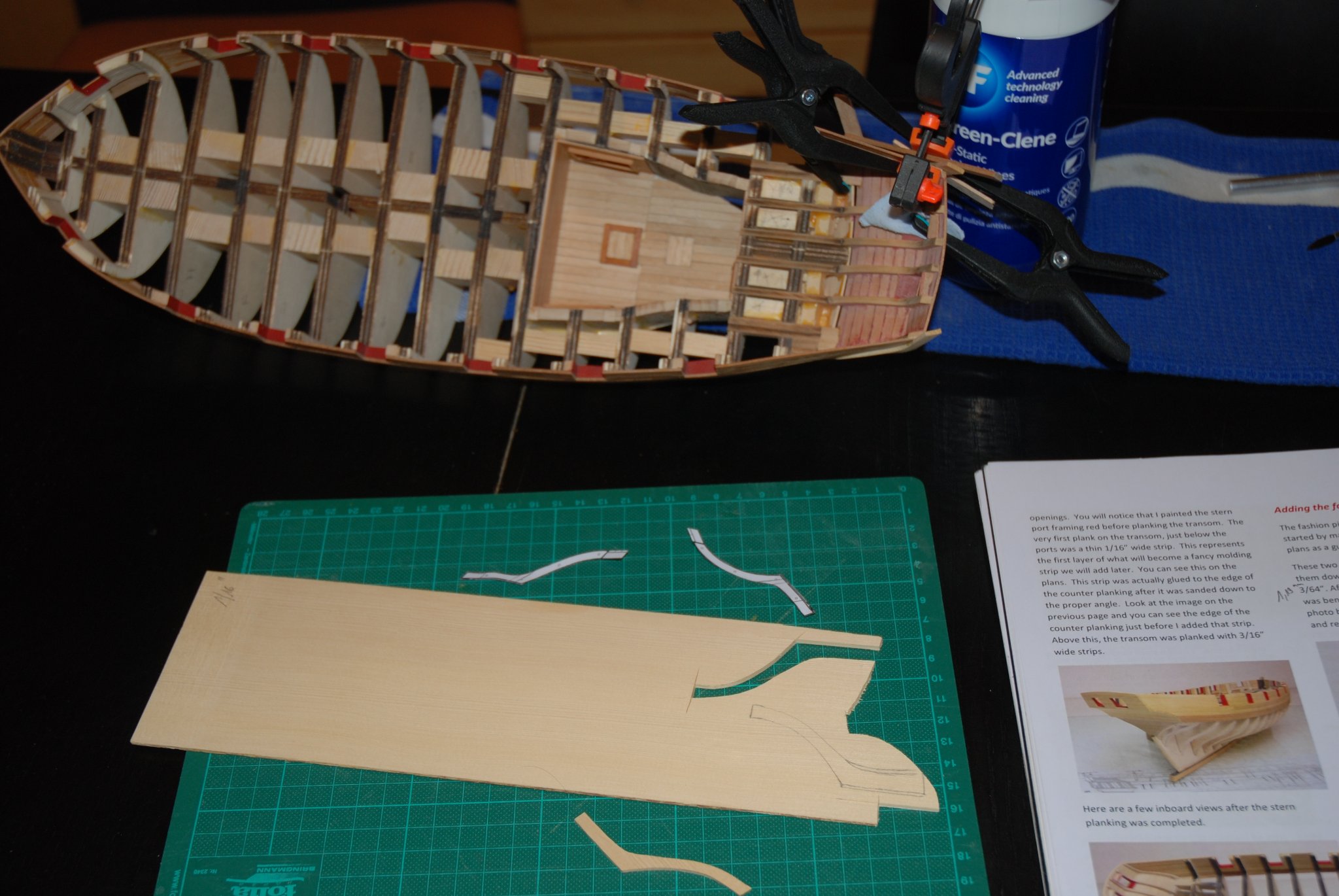
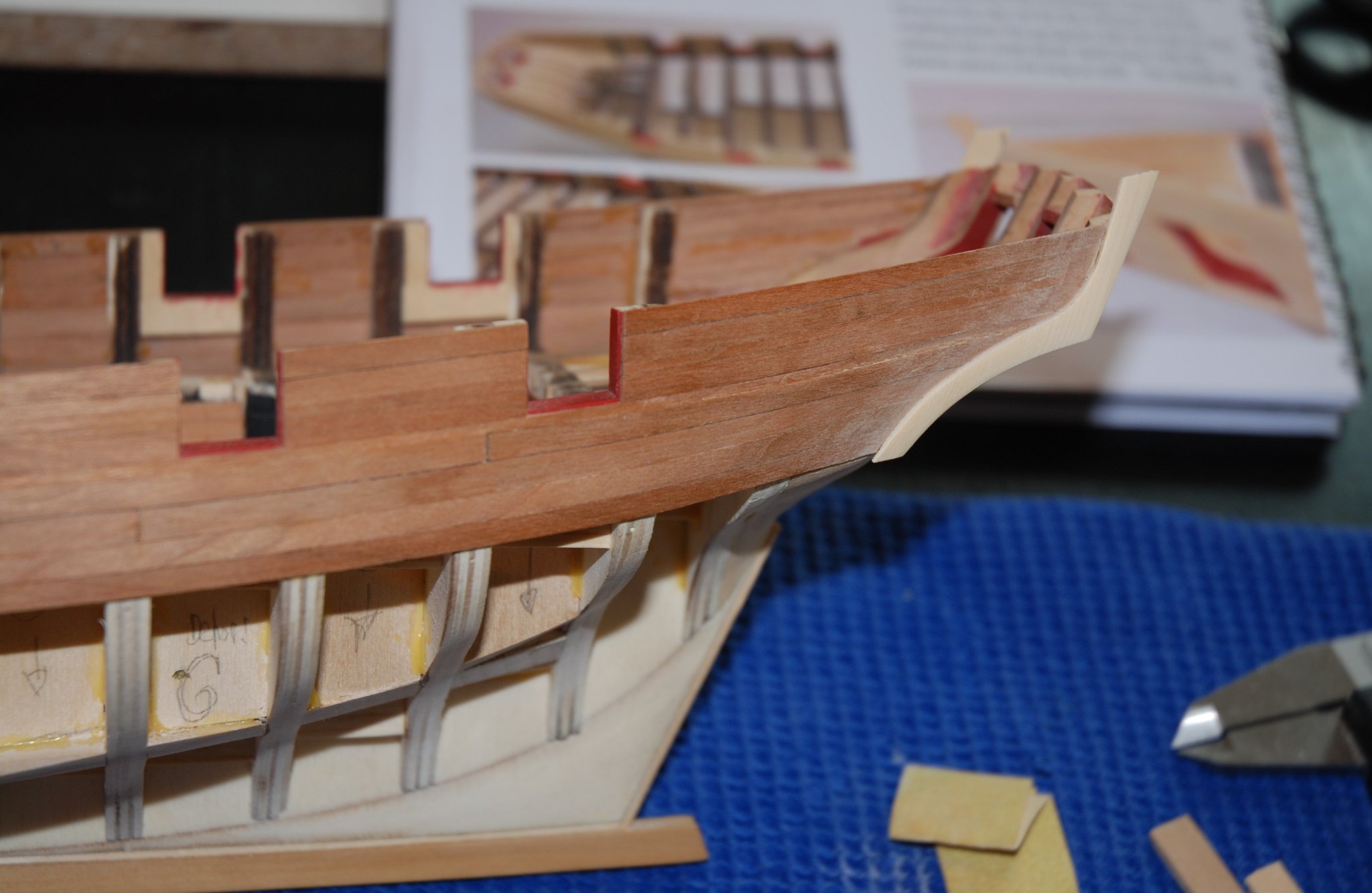
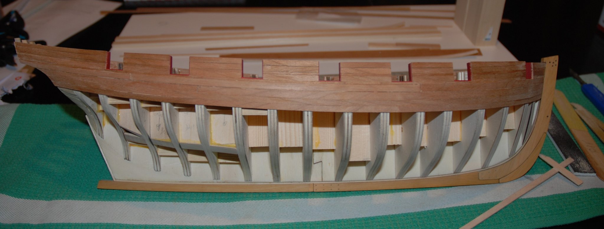
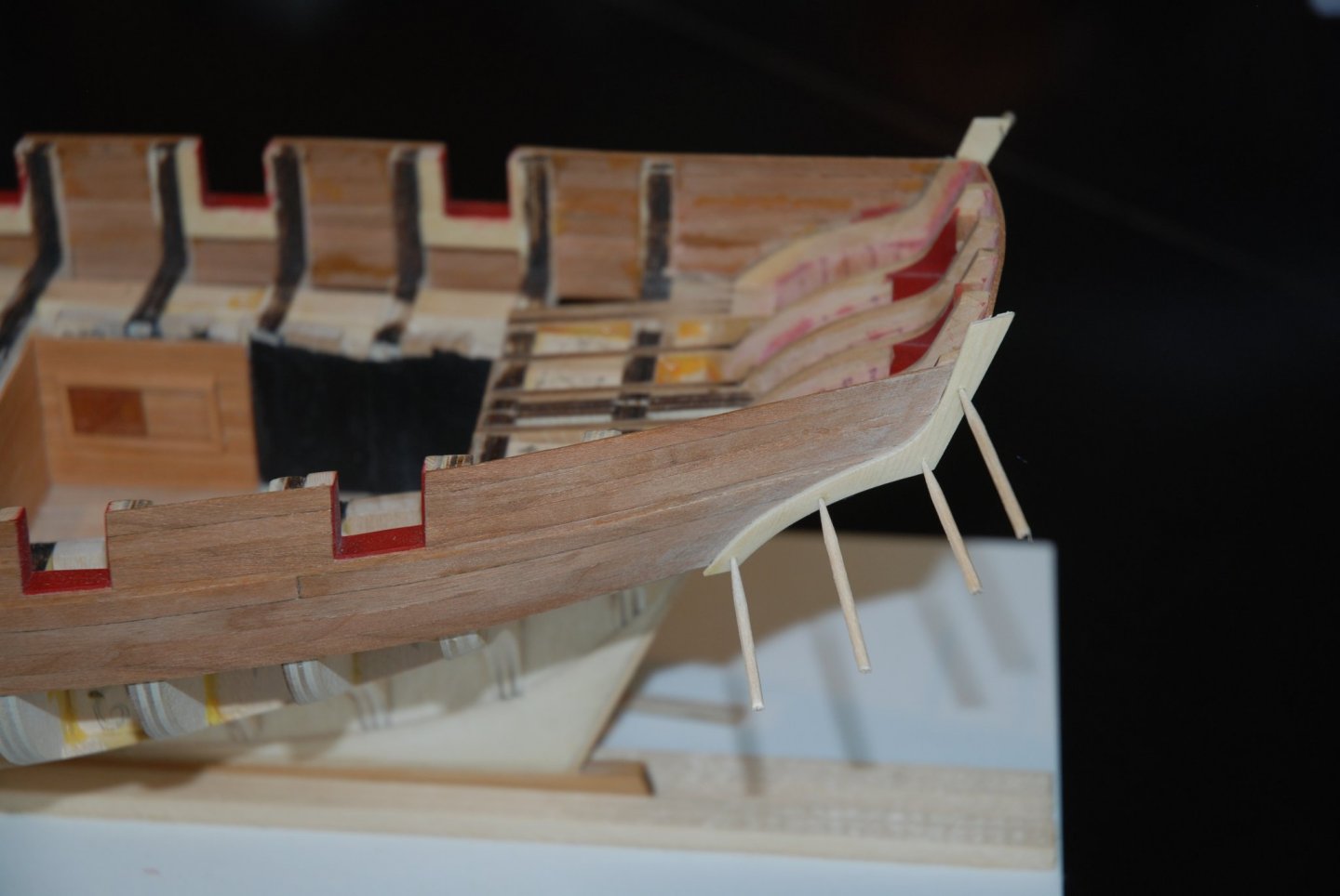
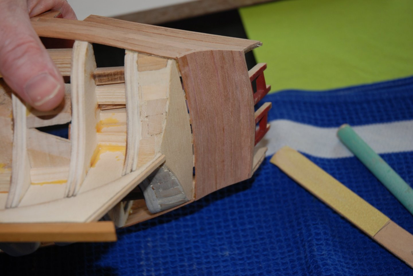
Thank you Chuck for your kind words. But when you have a model of this quality, so well designed, it is easier to get a good result. A lot of the credit goes to the designer... And thank you to all the 'Likes'. Setting up the fashion pieces. I decided to choose Alaskan Yellow Cedar as my wood for the fashion pieces. This wood has many advantages: it is easy to cut (I was able to use my cutter to cut the 1/16" thick pieces), it is easy to shape, and you get clean angles. Really a great wood! First, I cut my pieces into perfect replicas of the plan. But then I realized that it was difficult to position them correctly... So I got inspired by the method used by Stuntflyer (Mike). I traced on the model the front location of the parts with a pencil. I cut my pieces with the back part slightly wider. Once glued precisely to the line, I simply sanded the back part. Be careful not to forget to leave a space of 1/32" along the transom while in the part that runs along the counter you have to sand level. I glued the pieces with Titebond wood glue, which means that the preformed pieces must be held in place while drying. The pieces are then sanded on the back side and reduced to a thickness of 3/64". To finish, I simulated the reinforcement dowels by drilling 4 holes with reference to the plan. A sharpened pencil tip is inserted in the holes to round them perfectly and toothpick tips are glued. The whole is then finely sanded. I know that you won't see much once the fashion pieces are painted black but I hope that you will be able to see them under the layer of paint. I will now proceed as many modelers have done to lay the first two strakes of planks directly under the wales before adding the second layer of the wales. I have several questions that come to mind: - Is it time to paint the outside of the counter red? - I purposely left my fashion pieces slightly longer (they extend slightly past the bottom of the wales). Should I wait until I have installed my first 2 rows of planks before sanding them to the right length? - If the manual contains precise indications on how to tapered the first 2 strakes of planks at the bow, nothing is indicated on the width of the planks at the stern. Should I keep them at their 3/16" width or should they also be tapered? Thank you in advance for your help!


-
This paint job is really beautiful. Perfectly executed. And a big thank you for the explanation of the ebonizing technique.
- 79 replies
-
- 2
-
-
- Fifie
- Victory Models
- (and 1 more)
-
HM Cutter Cheerful 1806 by JpR62 - 1:48 scale
JpR62 replied to JpR62's topic in - Build logs for subjects built 1801 - 1850
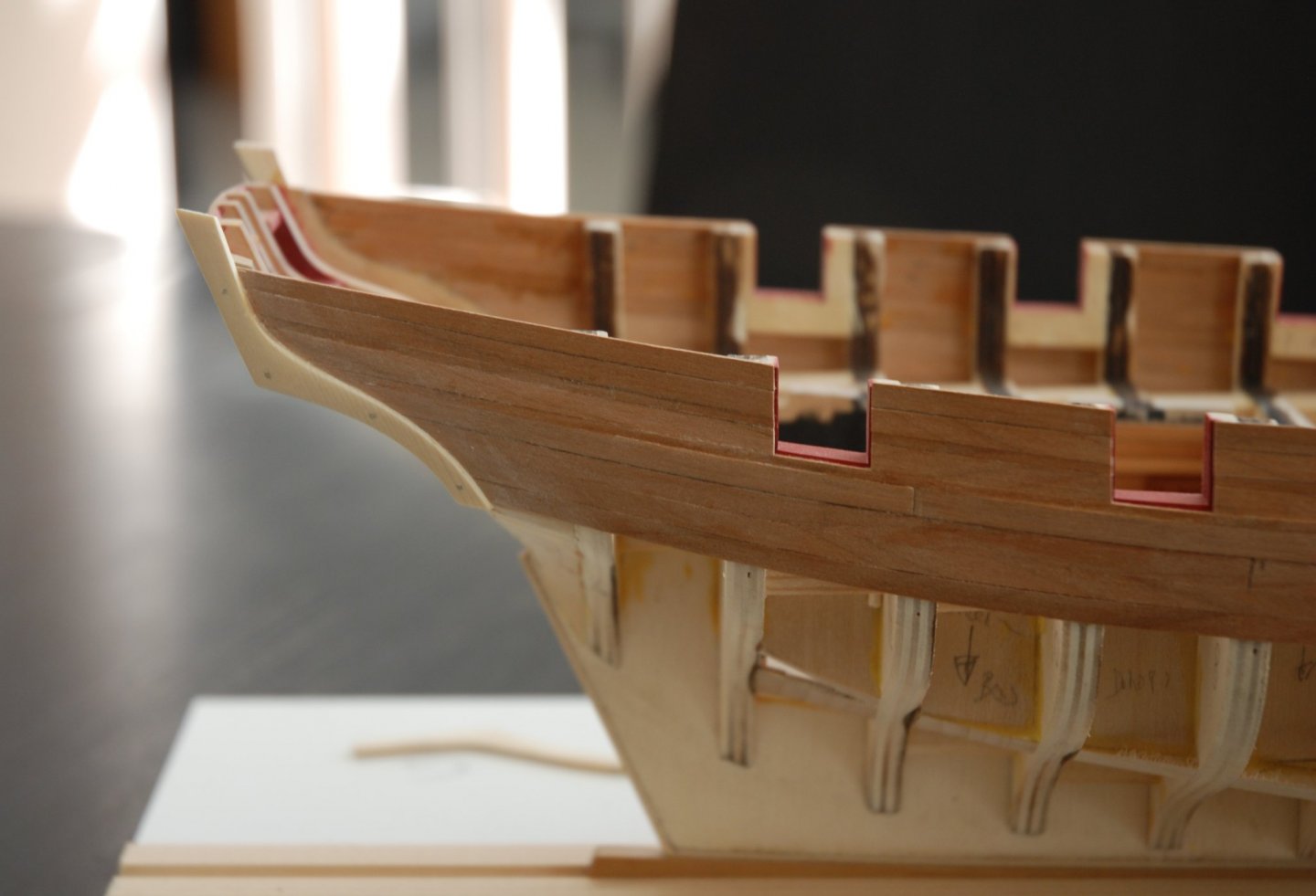
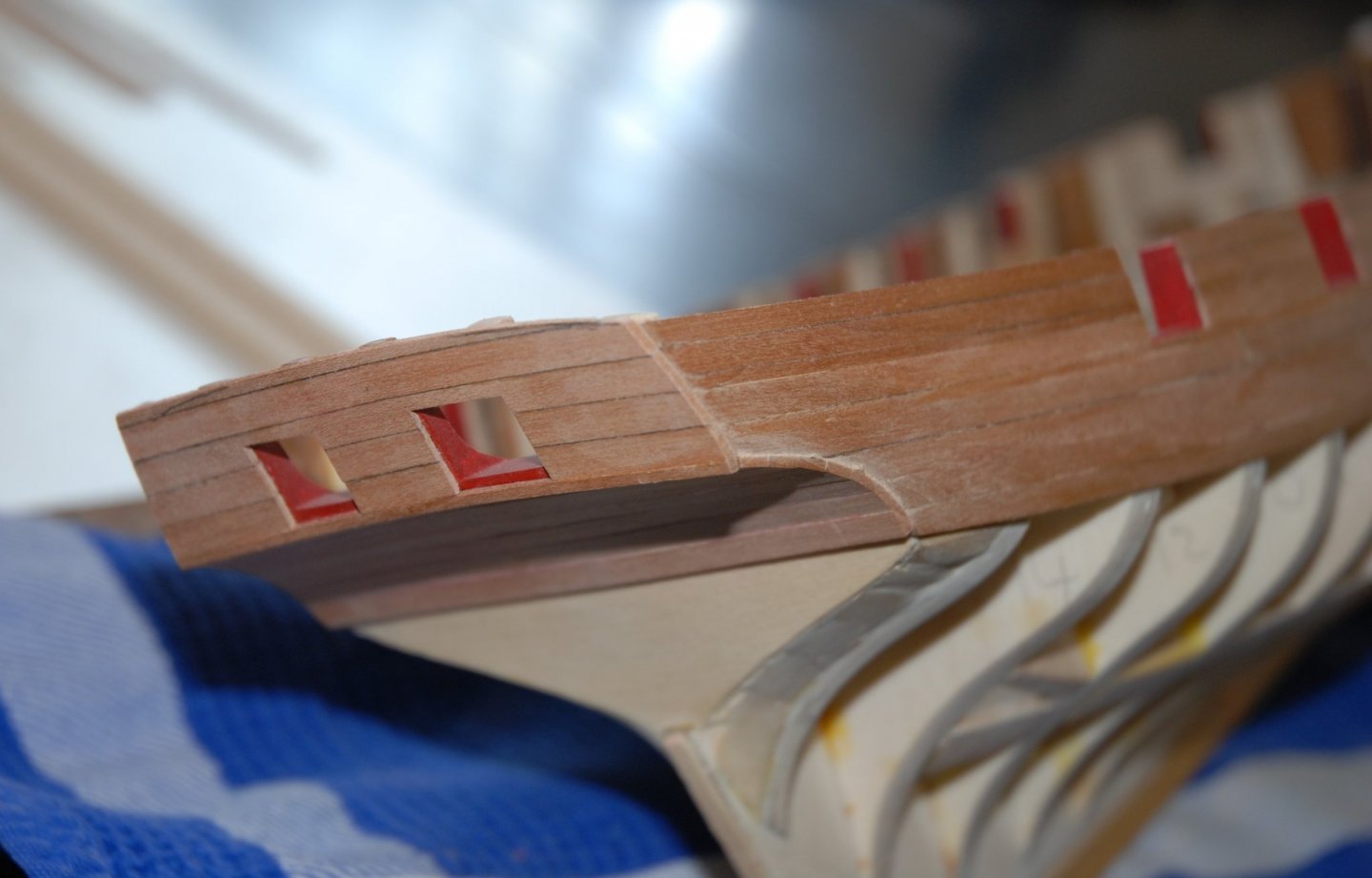
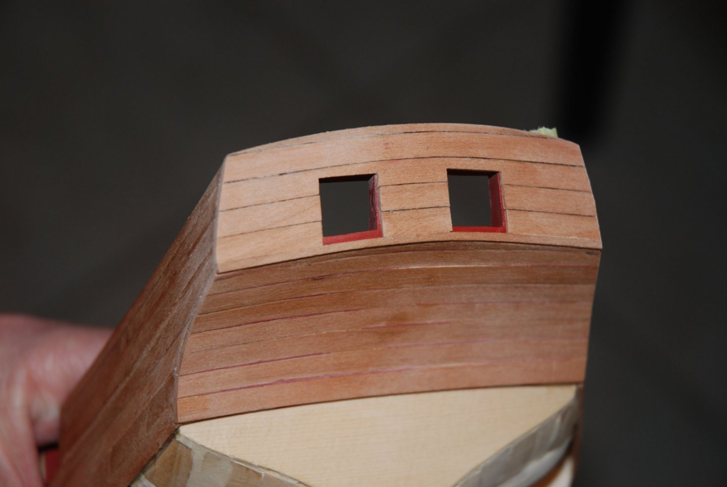
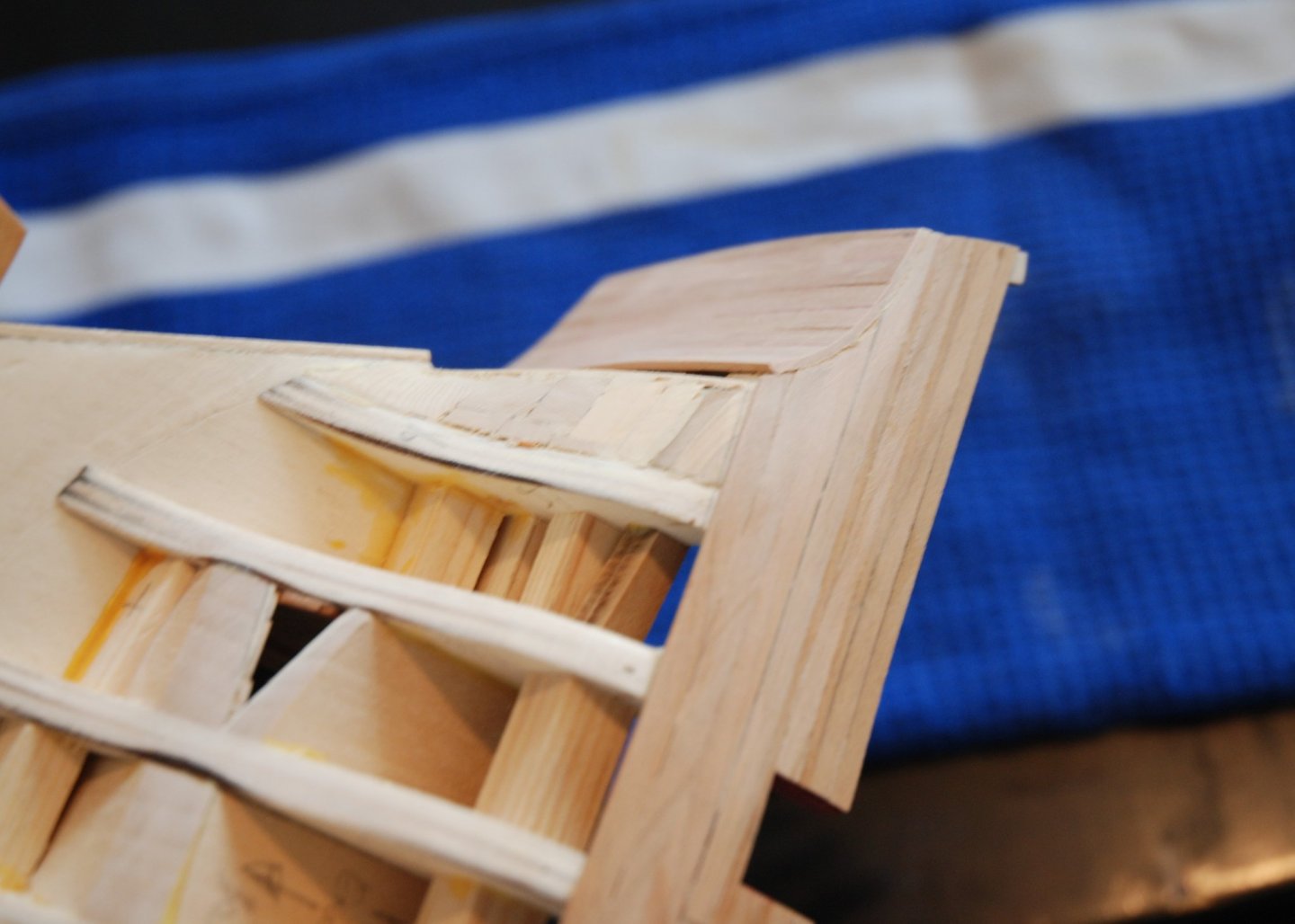
Thank you Christian and Glenn for your kind words and thank you to all the 'Likes'. In the end, I decided to opt for a cleaner finish on the inside because I felt that the joints between the planks were too visible. So I fill in all the joints and sand the whole thing to prepare the surface for the painting phase. You will notice that in the meantime the transom has been completed. I realized after the first layer of the bottom molding was installed that the rabbet at the bottom of the port opening was twice as wide. So I decided not to leave a rabbet on the upper part to respect the height of the port opening. As we will install the port lids later, we should not notice this small mistake... I then traced the upper curve of the stern with reference to a copy of the plan and gently sanded the top plank. In the picture above, the starboard curve is finished. And finally an exterior and interior view once the sanding is completed. Since I have a week's vacation for Easter, I'm taking advantage of it to make progress on this superb model. I now have to move on to a more delicate phase with the fashion pieces... I will first consult a lot of existing logs and reread carefully the manual.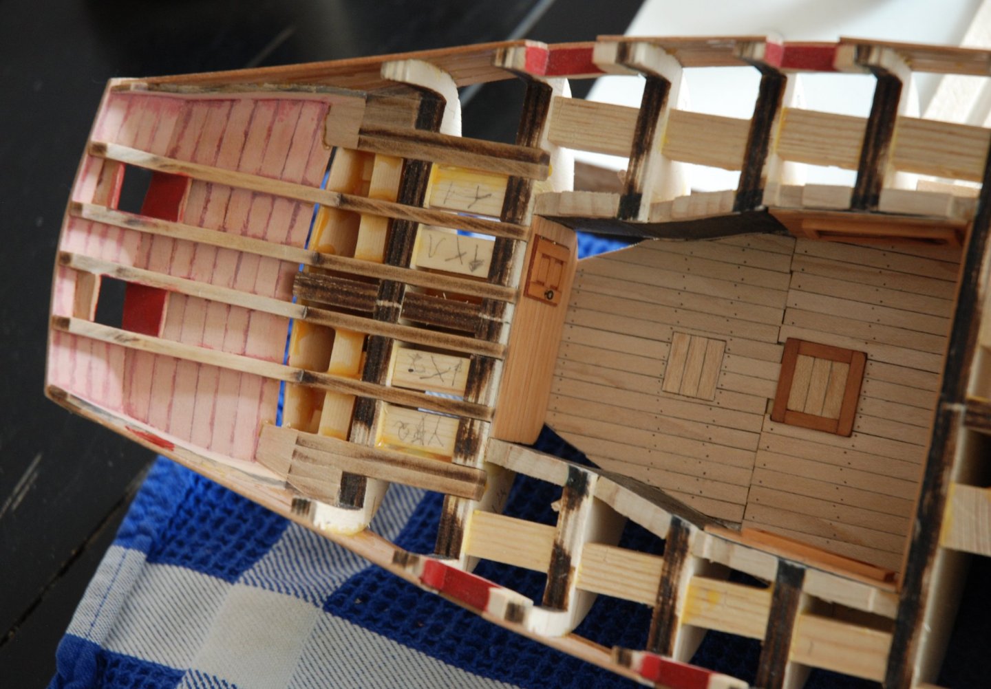
-
This barge has really beautiful curves. Very nice work. It moves with precision and great cleanliness. It brings back very good memories. This kit is so well thought out! And you can feel the fun you have building it.
- 185 replies
-
- 2
-
-
- queen anne barge
- Syren Ship Model Company
- (and 1 more)
-
HM Cutter Cheerful 1806 by JpR62 - 1:48 scale
JpR62 replied to JpR62's topic in - Build logs for subjects built 1801 - 1850
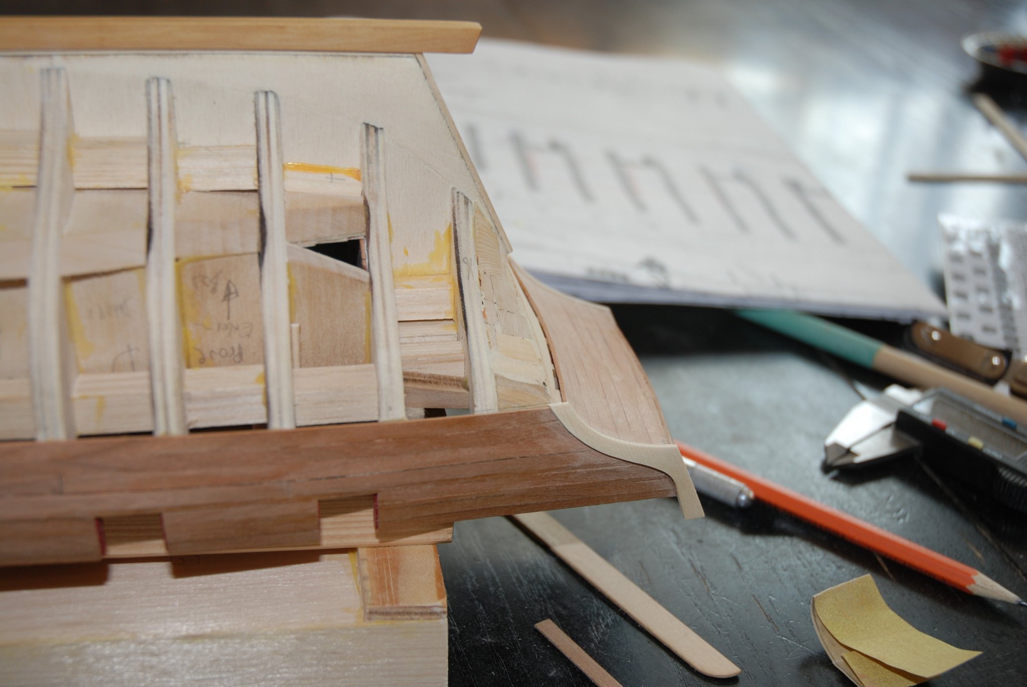
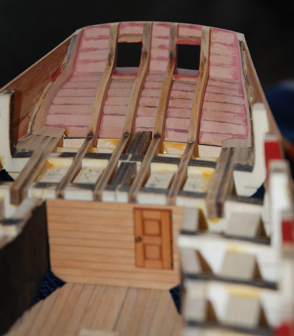
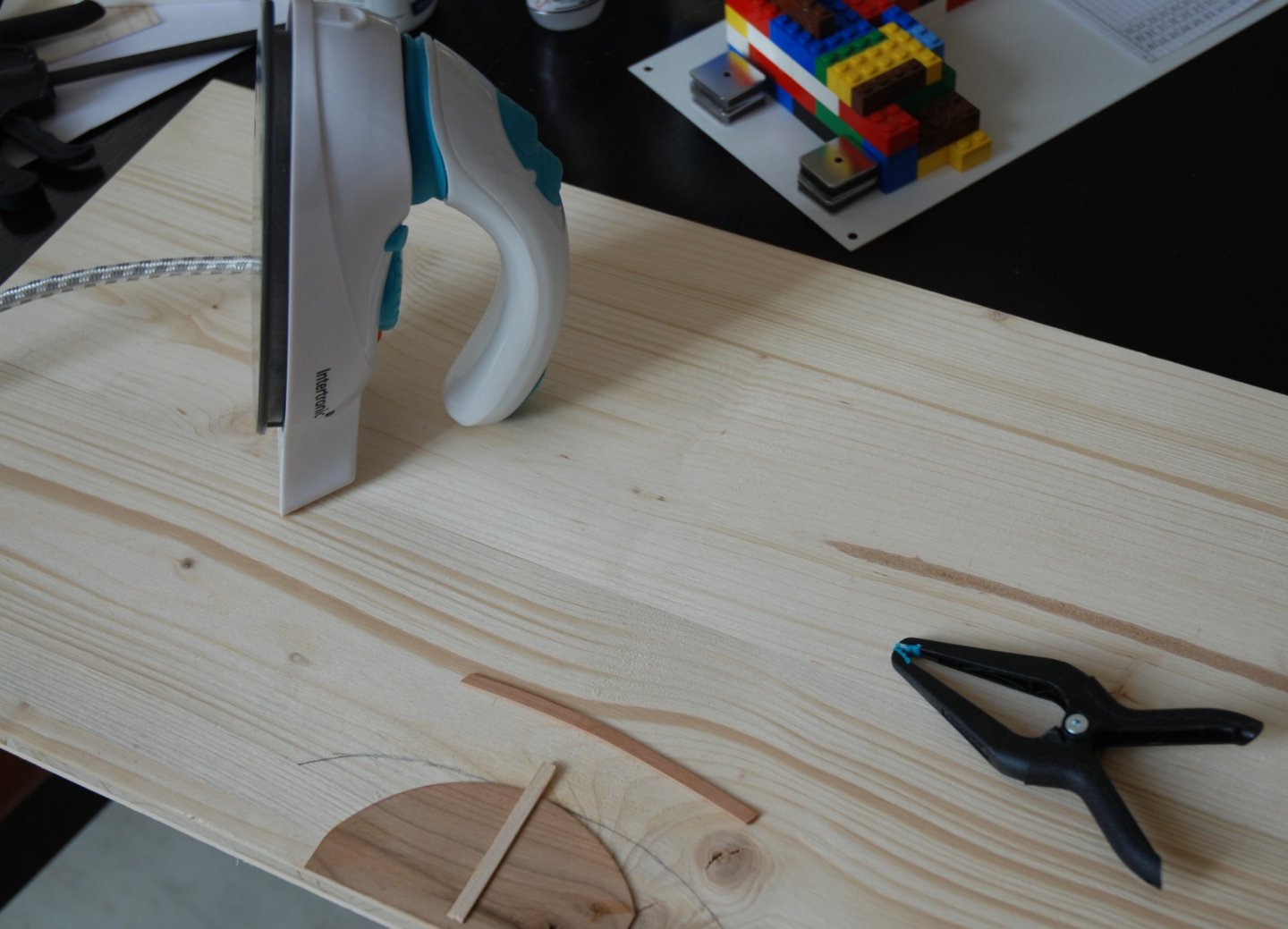
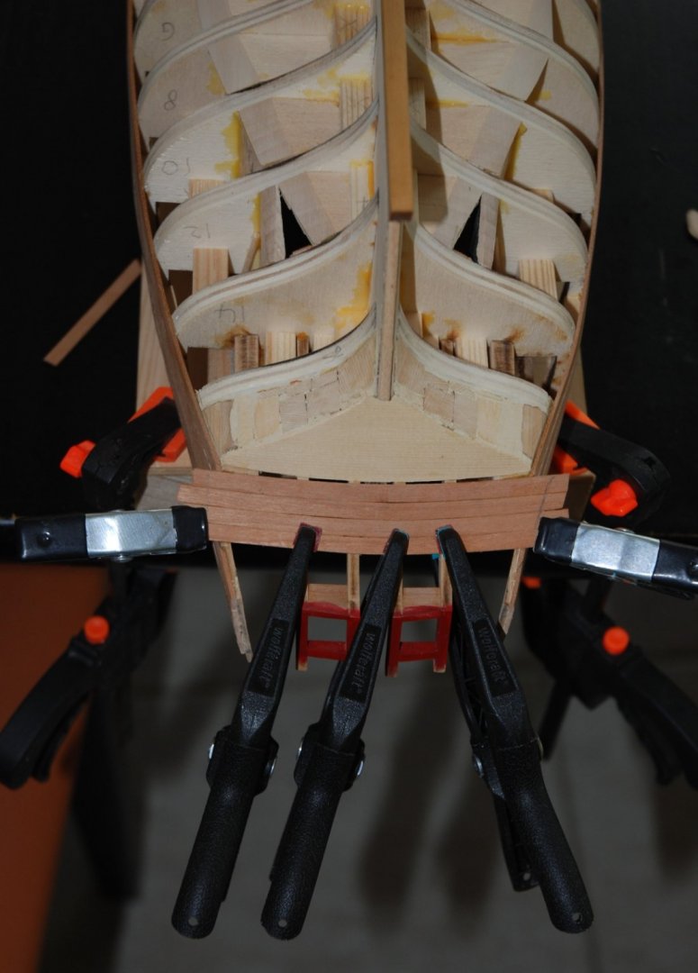
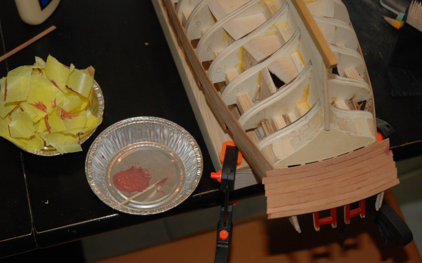
Thank you Ryland for your kind words and thank you to all the 'Likes'. I started working on the stern. I started by planking the counter. I first determined with the help of the plan the curvature to give to my planks. Then I have to admit that with the travel iron it's really easy to shape the planks. You just have to moisten the wood with your finger and bend it while passing the hot iron. And the plank keeps its curvature. For gluing, although no pressure is really needed, I still hold the planks in place with clamps while the glue dries. I can't master gluing with CA, it sticks my fingers more often than the planks... So I use good Titebond wood glue which requires 30 minutes of holding time for the glue to set. Once the whole counter is covered, as this part will be painted red, I allow myself to fill all the micro-cracks between the boards. Often, they are not even visible to the naked eye but with a magnifying glass or by observing against the light you can see them. I use acrylic wood filler (Jubin Akrilin) that I tint with a drop of acrylic paint and add a little white glue. I mark the areas to be filled with protective tape and use a toothpick to push the filler in. The over-lengths are first shortened with my proxxon and then refined with sandpaper. The whole thing is then carefully sanded. The interior has been lightly cleaned of a few small traces of glue. I don't know yet if I'll fill the inside joints between the planks perfectly or if I'll leave them like that. I don't mind that you can guess the joints between the planks... It's time to move on to the upper part of the stern.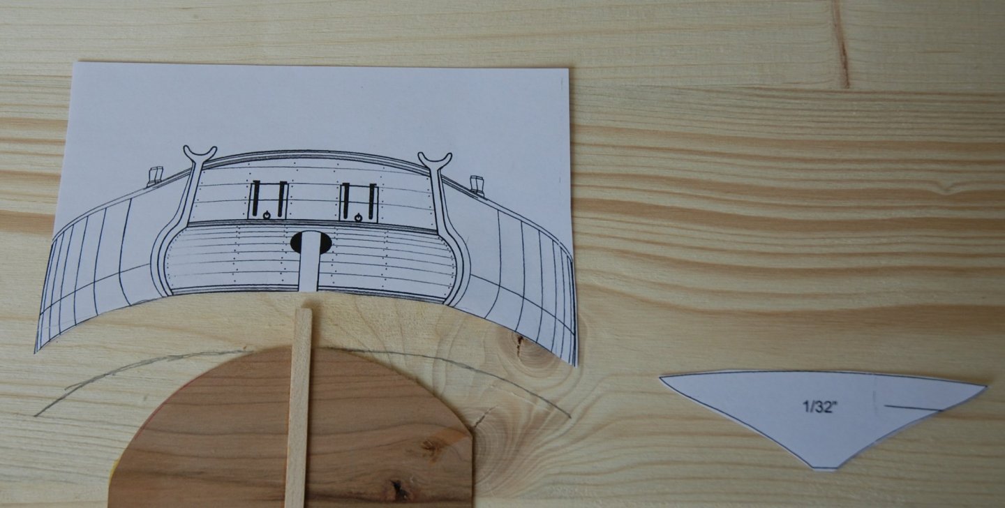
-
Very nice paint job. The rust coloured stain is really superb and the ebonizing technique seems perfect. Complicated to put into practice?
- 79 replies
-
- 1
-
-
- Fifie
- Victory Models
- (and 1 more)
-
Great work Glenn and always so many tips and information!
- 778 replies
-
- 4
-
-
- cheerful
- Syren Ship Model Company
- (and 1 more)
-
Always so clear and precise. What a nice job!
- 201 replies
-
- 1
-
-
- Duchess of Kingston
- Vanguard Models
- (and 1 more)
-
Wonderful work on this cross section Dave ! It is as usual a precise and perfect work and these pillars are beautiful.
-
HM Cutter Cheerful 1806 by JpR62 - 1:48 scale
JpR62 replied to JpR62's topic in - Build logs for subjects built 1801 - 1850
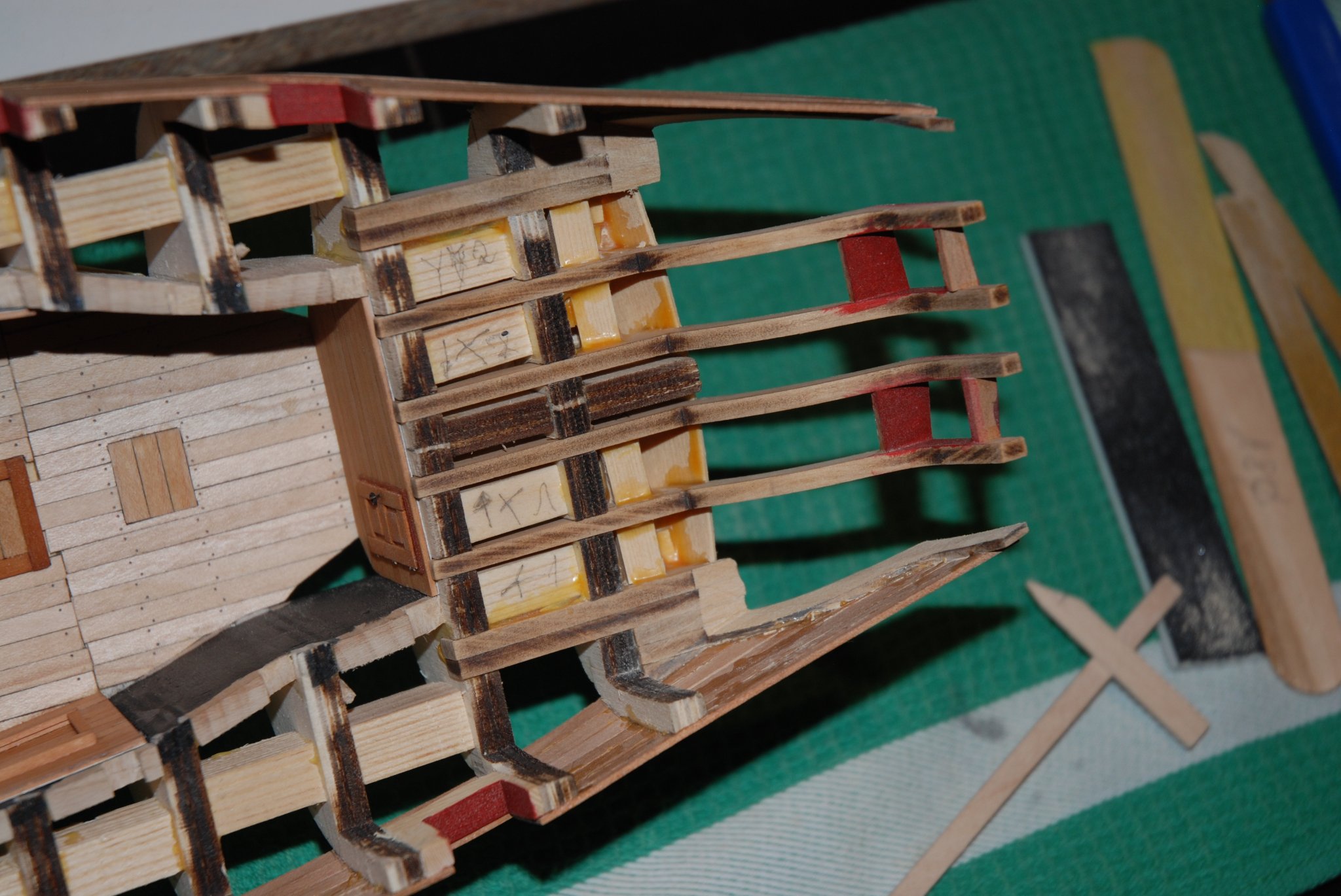
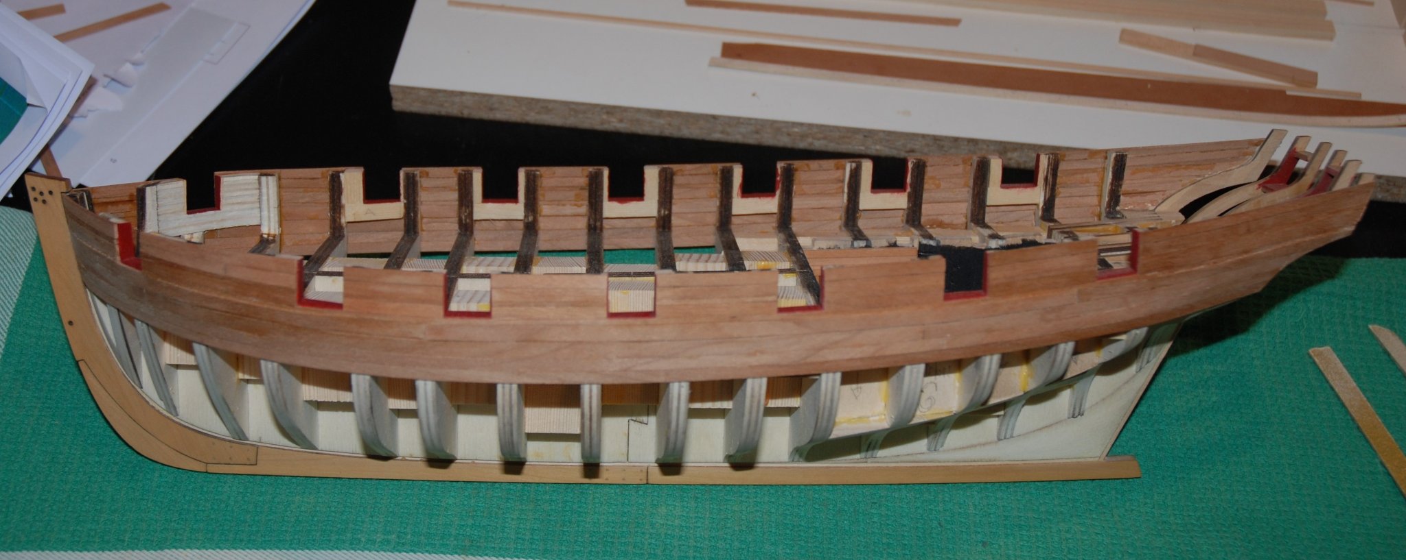
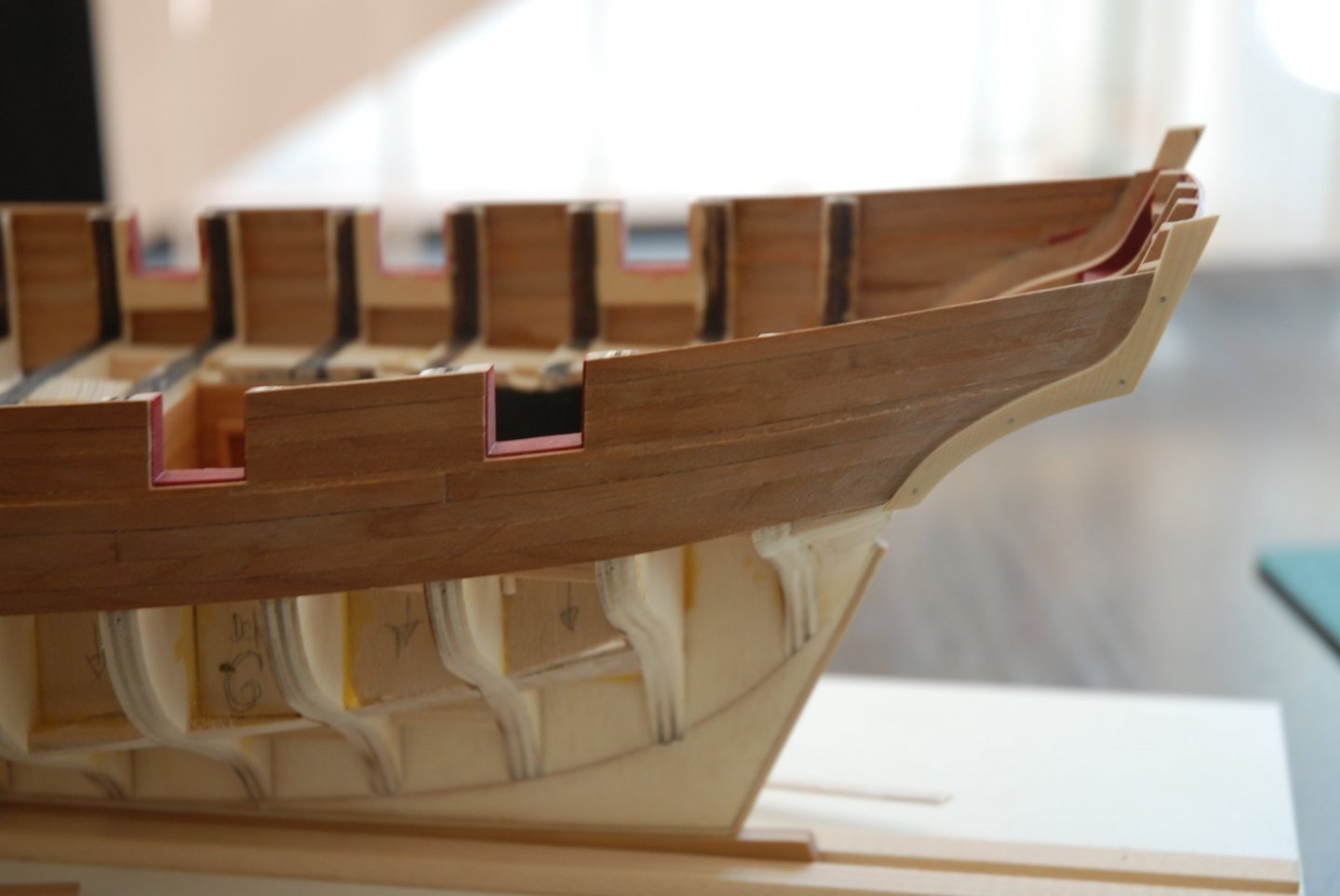
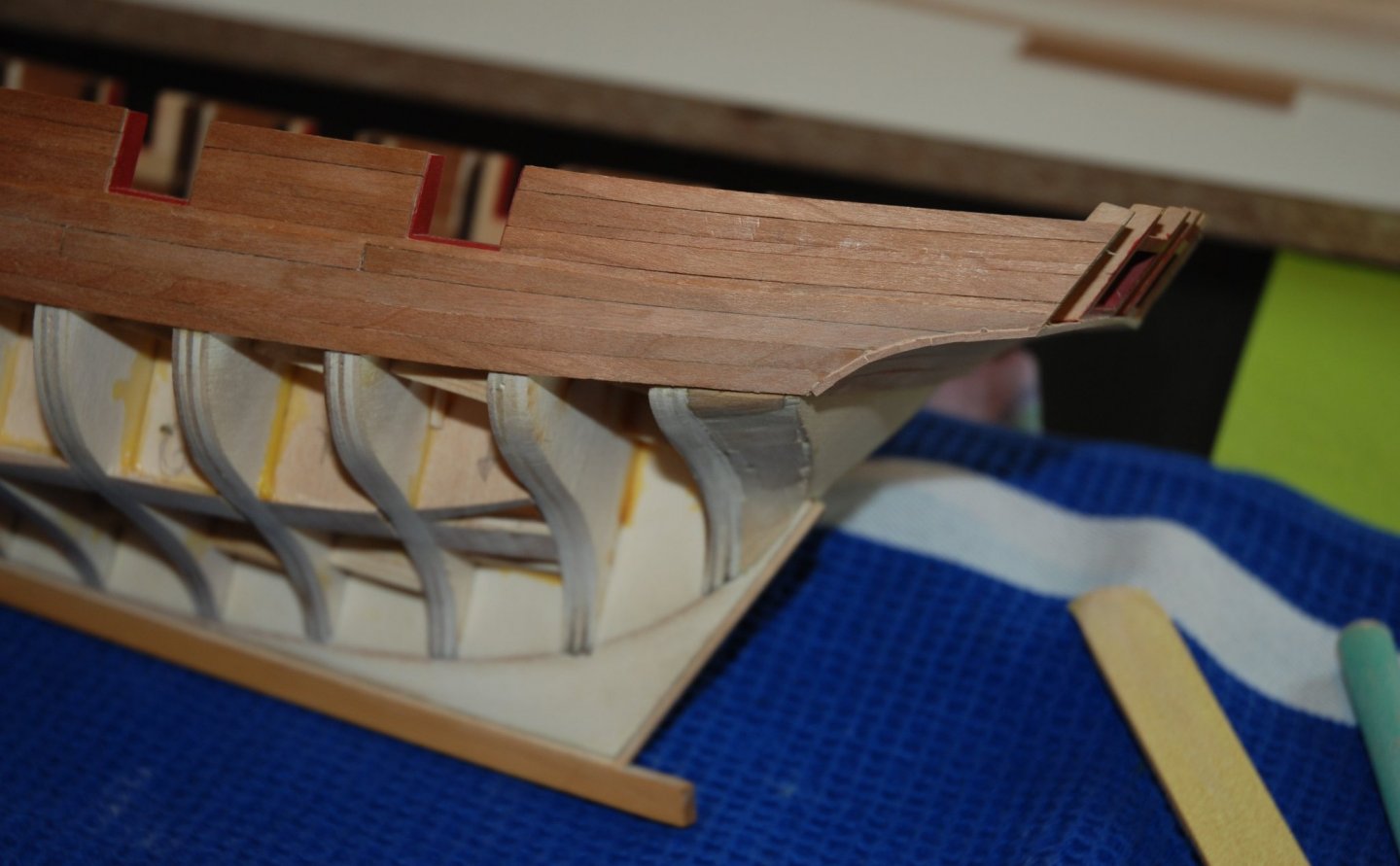
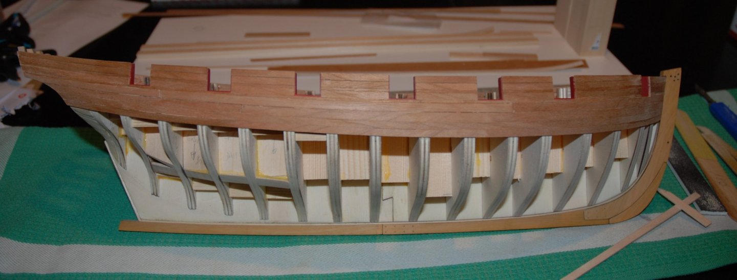
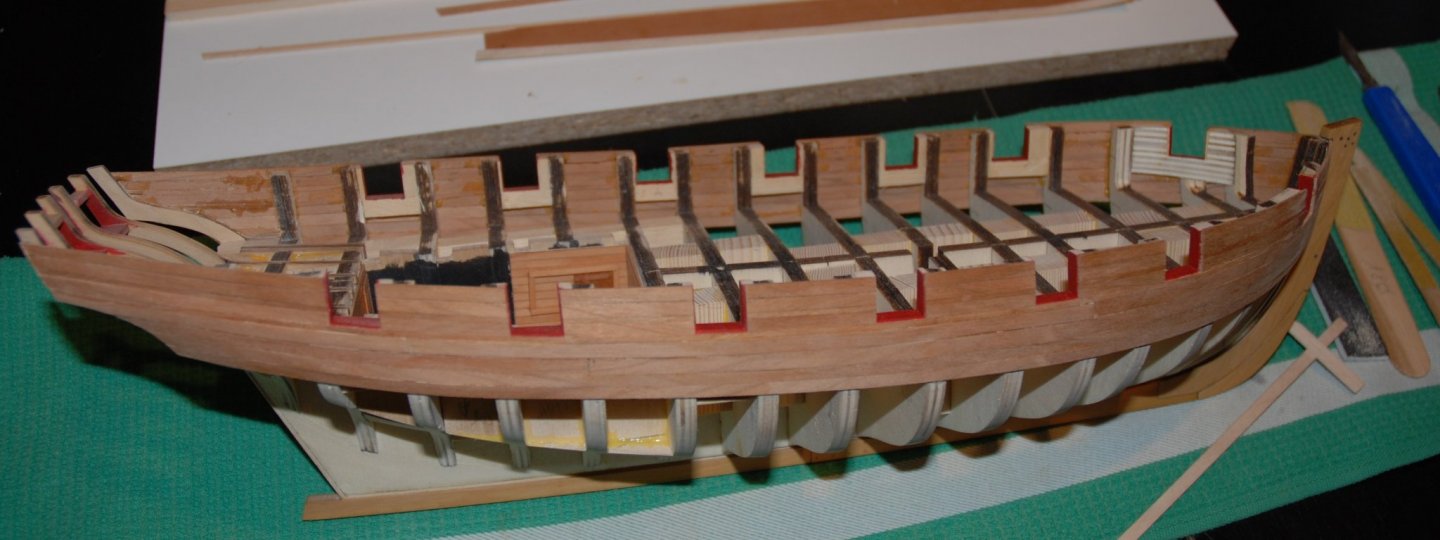
Thank you to all the 'Likes'. The strakes above the molding have been glued, so take your time and measure the length of each segment precisely. I marked one edge of each plank with an HB pencil to simulate the tarred seems between each strake. I also glued the edges with a dark wood glue. You will notice that the two outer frames of the stern have been reduced to a thickness of 1/16". Most of the work was done with a sanding drum mounted on my proxxon flexishaft and then the last few millimeters were carefully removed with various sanding sticks. At the stern, the last row is slightly below the top of the outer frame, but this has been noted in several build logs and I don't think it should be a problem. Next step: planking the stern and always so much fun !


-
Wonderful! This brig is absolutely gorgeous. A real pleasure to admire all the perfectly executed details.
- 950 replies
-
- 1
-
-
- syren
- model shipways
- (and 1 more)
-
WOP -> Wipe-On-Poly Unfortunately, very difficult to obtain in Europe ☹️ Scrubbyj427, Thank you for sharing this great technique !

-
HM Cutter Cheerful 1806 by JpR62 - 1:48 scale
JpR62 replied to JpR62's topic in - Build logs for subjects built 1801 - 1850
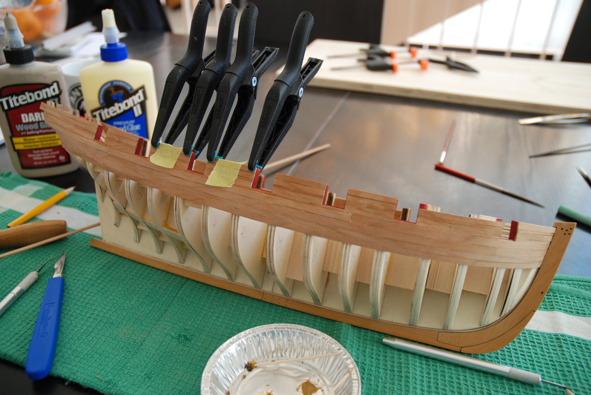
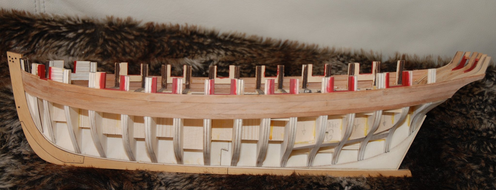
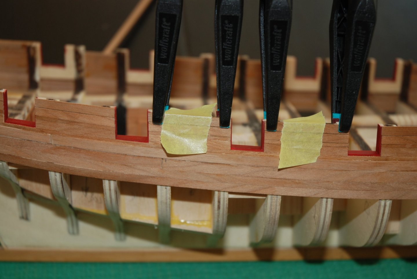
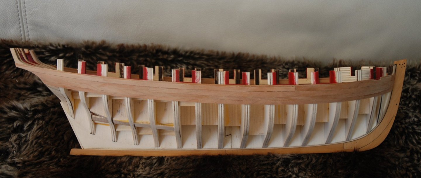
Thanks to all the 'Likes'. This week, I put the planking between the wales and the first layer of the molding. For this I used the method described by Chuck and proceeded to shape the planks using a small travel iron and a hair dryer. I have to say that this method works pretty well and makes it easier to get the planks in place. I found that the second strake, the one that fills the space, was still difficult because the width of the planks must be really precise. The next strake should be easier as it will consist of a constant 5/32" width, although here it will be the length that needs to be precise to leave a 1/64" gap around each gun port.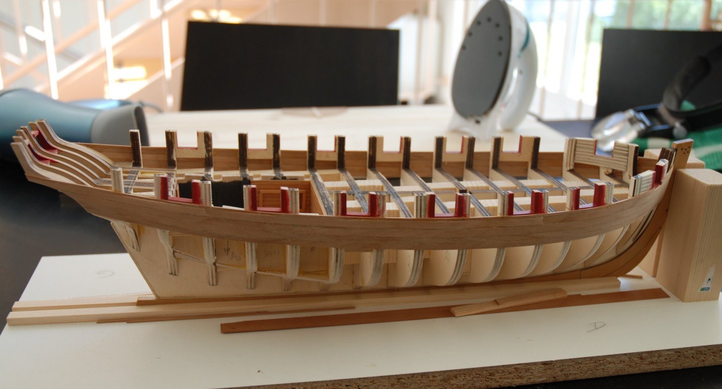

-
What a great example of perfection! This is absolutely top notch work.
- 607 replies
-
- 2
-
-
- winchelsea
- Syren Ship Model Company
- (and 1 more)