
Haze Gray
-
Posts
194 -
Joined
-
Last visited
Content Type
Profiles
Forums
Gallery
Events
Posts posted by Haze Gray
-
-
Thanks Gents, that's very kind of you to say! I really should provide an update - I've been sanding the hull and making the turrets, but I have 3 hulls in addition to the Charles Martel that I'm sanding and it's been kind of cold out in the garage so I've slowed down a bit. maybe In another week or two I'll post that update.
-
Hi haven't tried this but thought I would share (as it might have uses outside of fine modeling).
- thibaultron and Canute
-
 2
2
-
11 hours ago, rraisley said:
I've been working with Fusion 360 for a few months now, and am able to model many things fairly well. My son has 2 filament printers and one resin printer, but in printing guns for my 1:98 Victory cross section, has had a lot of problems. MANY failures in resin printing, replacing several film vat bottoms (or whatever they're called) and failed objects. Finally got enough to work for the model.
Now he's tried a desktop size barrel, which also failed, and he's basically given up on them for me. All HIS stuff works great, but very few on mine.
One problem I've had with the STL files created by Fusion 360 is that some components come out hollow, while others are solid. For example, on the barrel, the main barrel was solid, the trunnion and gunlock hollow. On my gun carriage, the sides and axtrees were solid, while some other parts were hollow. I could only confirm a solid model by starting with one solid part, then JOIN another part to it, making the combination solid, and doing that for every piece in the assembly, which was a real pain.
Ambient air temperature can make a bid difference with resin printers - you might want to try putting the resin printer in a closet with a small space heater on low, get the air temp in the 70's or low 80's and see if you get more successful prints.
- thibaultron and Canute
-
2
-
2 hours ago, Kevin-the-lubber said:
Please, no more, I can't take it :-). Way, way back I came to these forums because I'd just bought the heller victory and needed to figure out some really simple things. After seeing Danials amazing work and that of several others I became lost to this hopeless pursuit for making the detail better. Now you're throwing self-printed hulls into the mix. I have the kit - both filament and resin printers. I'm starting to get a handle on F360. It's not looking good. More seriously, I'd love to be able to build the entire kit from scratch, since that would allow me to design in all the detail I could ever wish for.
Those are some very impressive models, Haze, and if it wouldn't lead me astray I'd love to know how you set about designing them.
I think Bilge rat is probably right about the rabbit hole - but I'd say you're probably further down that hole than you think! This topic has a lot of great information: https://modelshipworld.com/forum/34-cad-and-3d-modellingdrafting-plans-with-software/
How things are done in fusion similar to how things are done in blender - basically tracing hull lines and then some lofting operations. I'd recommend just finding plans of a ship that you're passionate about and heading over to that "model drafting plans with software" topic and start posting your attempts, you'll get a lot of help. Next time I do a hull I'll make a video to show you a few basic techniques.
If you like to witness torture: here's 40 minutes of me hating life and trying to model a French Torpedo Aviso.... lofting hull in fusion 360 - YouTube
- igorcap, mtaylor, thibaultron and 1 other
-
4
-
1 hour ago, wefalck said:
What about cost - there most go a considerable amount PLA going into such hulls ? How do you smooth them after printing ?
Wefalck, I forgot to address your question on smoothing out the lines - I typically sand down the layers (sometimes by hand, sometimes using a small orbital sander) and also I sometimes put a very very thin coat of gesso and then sand that flat. when I say thin, I mean very very thin layer of gesso - it can work really well but I've not perfected that technique but it can work extremely well.
-
15 minutes ago, wefalck said:
What about cost - there most go a considerable amount PLA going into such hulls ? How do you smooth them after printing ?
Cost can vary depending on the skin thickness and the infill percentage - these days I go with 0.7mm skin and 20-25% infill depending on the part - and the cost range from ~$60 - $120 for the hull. I've noticed though that some resin ship kits can get pretty expensive, more than what it costs to print a large scale one in PLA.
-
Glad I found this thread - I've been designing and printing hulls for the past few years (mostly designing as I like that part the most) but do print some in large scale using PLA+, but I did pick up a resin printer so i can start printing them out in a smaller format for even more fun. I've been using fusion and it took me awhile to figure out how to do it (that was back in 2018!) Largest hull I have is about 1.7M long but I have a few plans for 2+ meter long hulls.
Since most of what I print is large I spend a lot of time maintaining machines (especially the wiring) and used to use a battery backup until I figured out how to configure printing resume after power loss (happens occasionally where I live due to trees!). I have been refining the design for the hull joining tabs that helps with alignment - not perfect yet but what is?
-
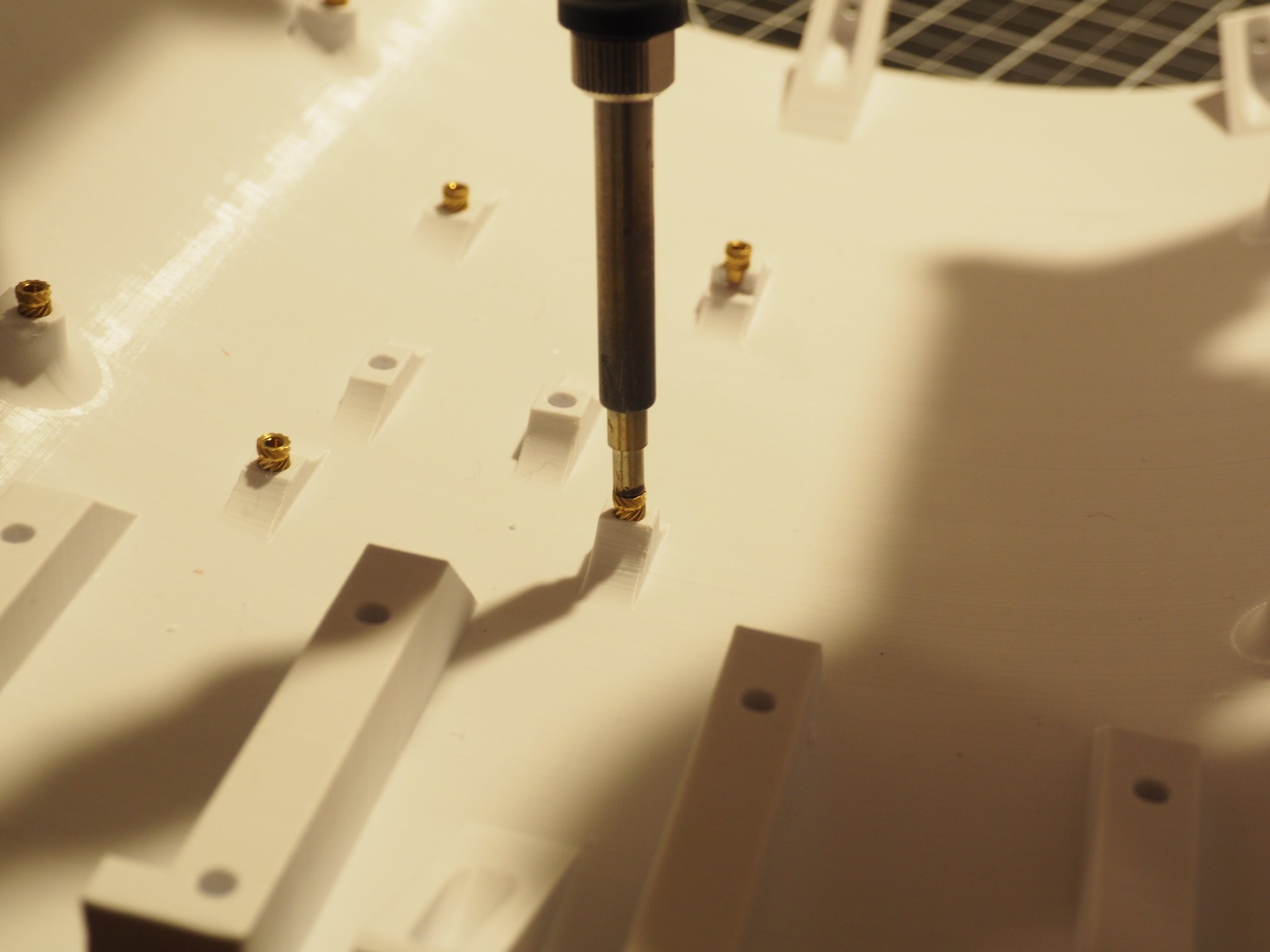
Another update here - after finishing printing all the hull sections yesterday I spent some time cleaning them up a bit. Prior to permanently joining them all together I needed to put in some of the threaded inserts for stepper mounts and the arduino control board. The "heat inserts" I use are from Mcmaster Carr: heat inserts | McMaster-Carr and they come in a many different sizes. I typically use 3mm inserts with 3mm machine screws, and there's several different types available even in just the 3mm size. The row on the left are for 3mm and there's a 2mm example on the right side in this photo.
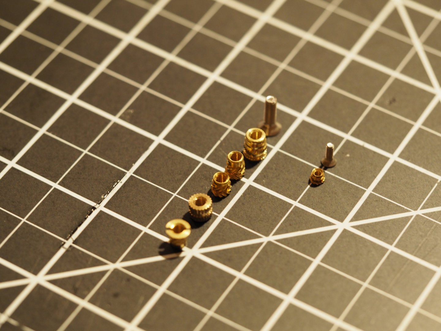
Note I would recommend you spend the extra money on the heat inserts from Mcmaster Carr, the cheap ones you can get off ebay are (in my opinion) garbage. Easy to install a 3mm insert using a soldering iron with an adapter or thin tip:
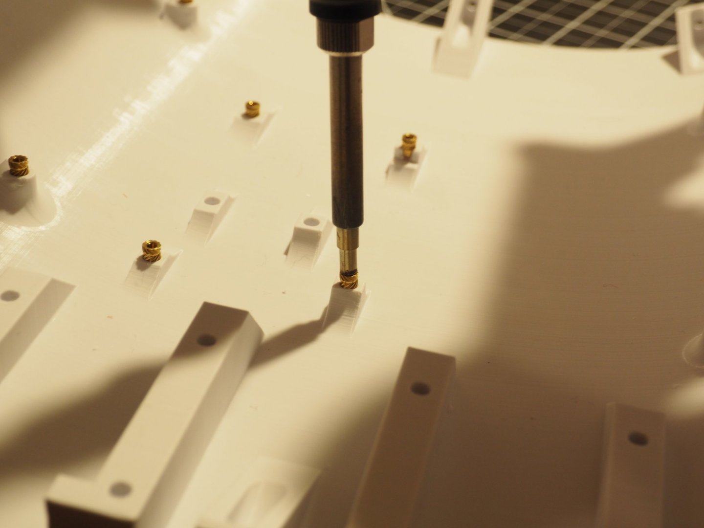
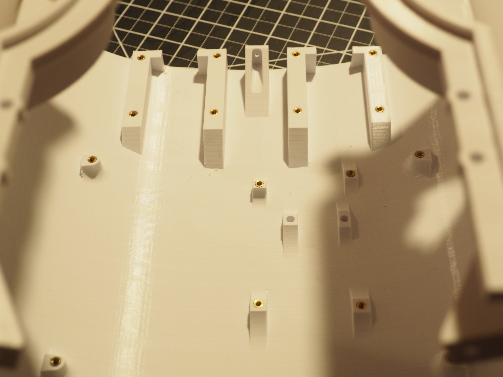
And here's what it looks like with most of them installed. The aft most inserts are where the motor mounts get bolted to.

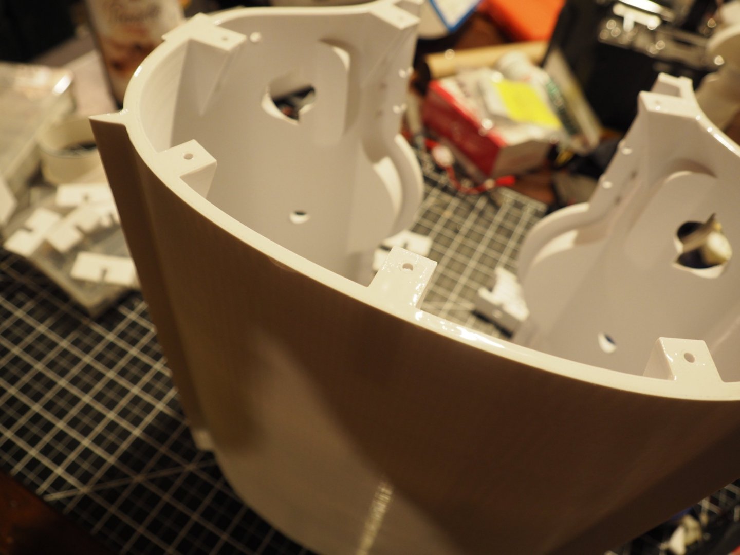
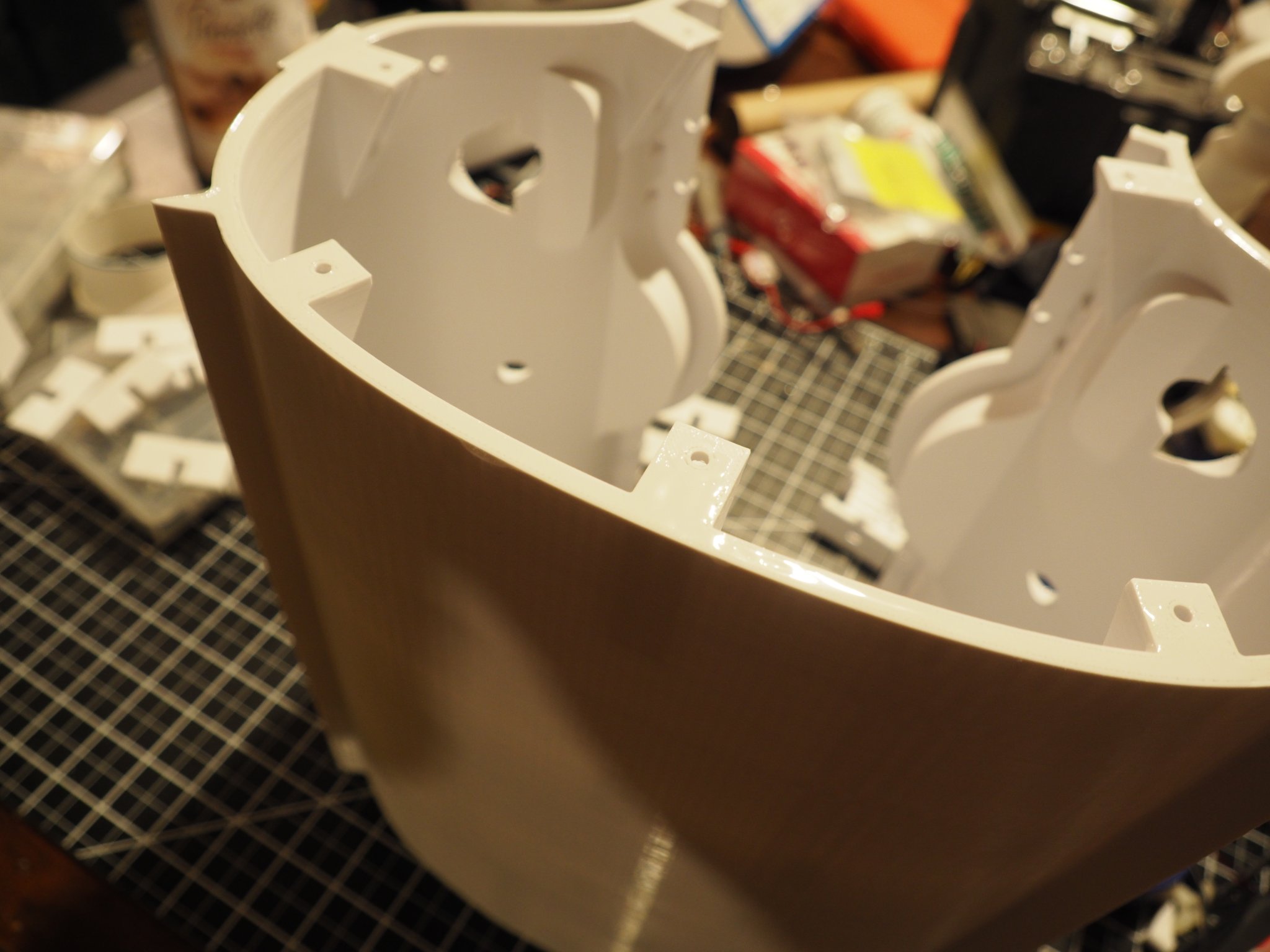
Next I started gluing the section together - a thin layer of 5 min epoxy this time since I didn't have any 10 min lying around. I find that 5 min epoxy is okay but sets quick and sometimes if there's some alignment issues your racing against the clock in a most uncomfortable way. So I always check and recheck how things are fitting together before I mix up the glue. I also take time to figure out which tabs will need more clamping pressure and have those handy. You can kind of see the glue in this photo, keeping it to a thin layer means less ooze to wipe off.
After gluing 3 pairs of two sections together I sent them aside for an hour or so to fully cure
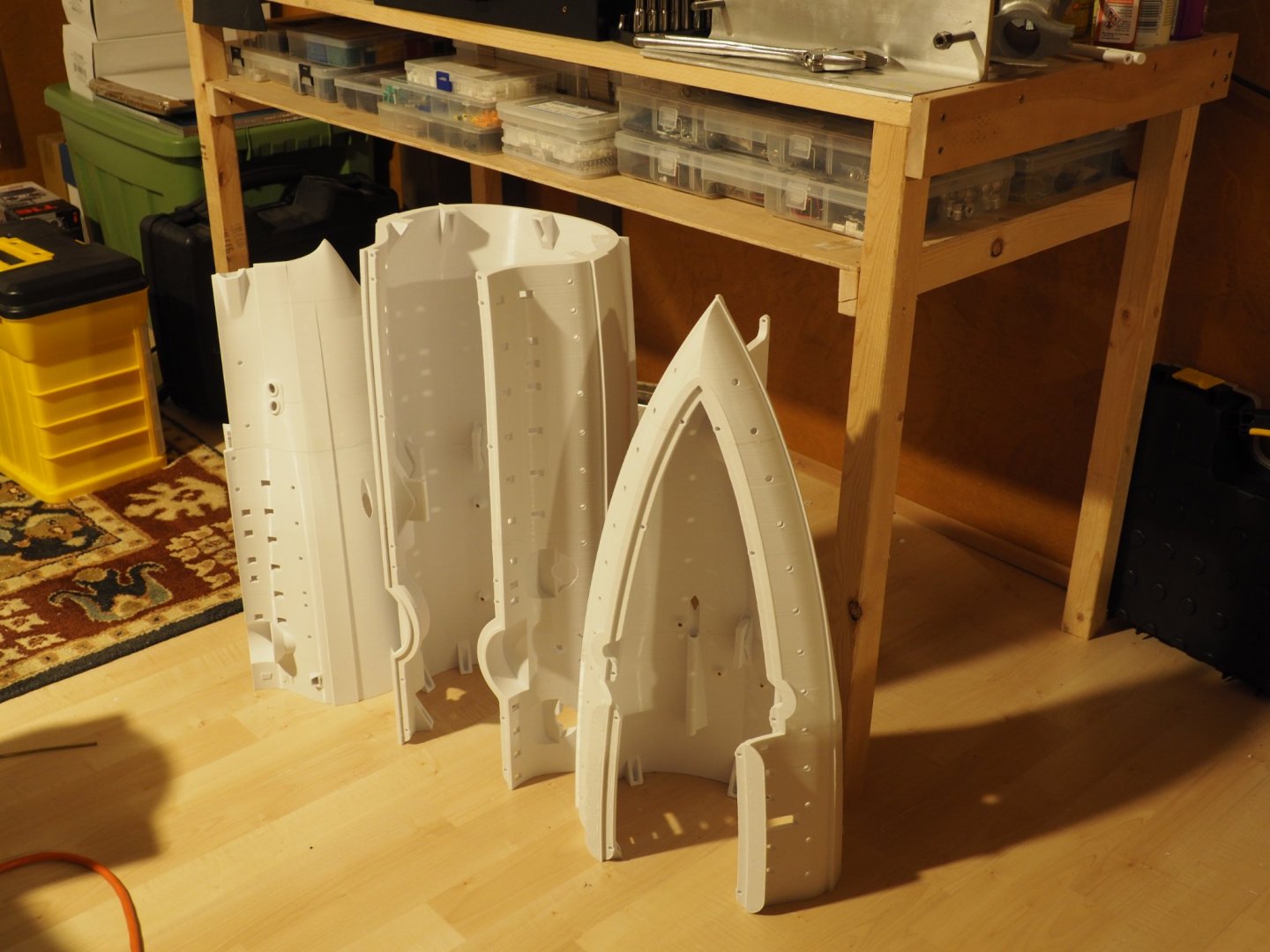
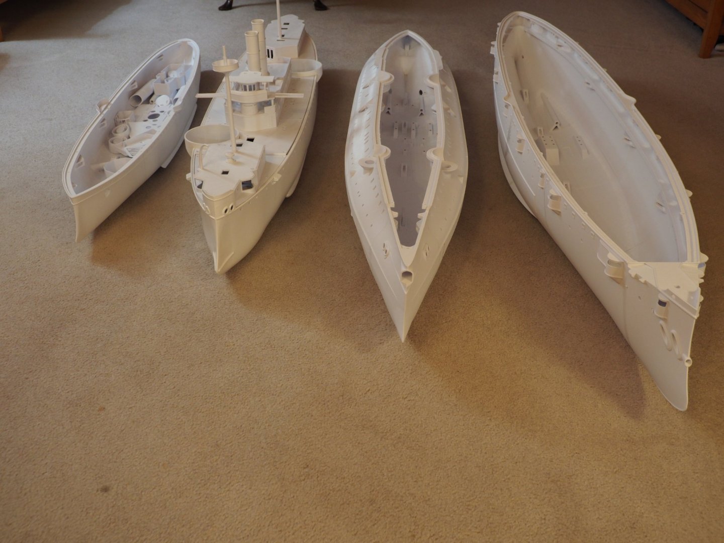
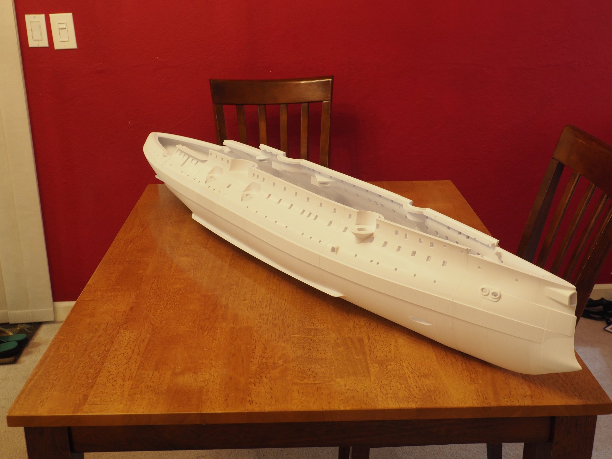
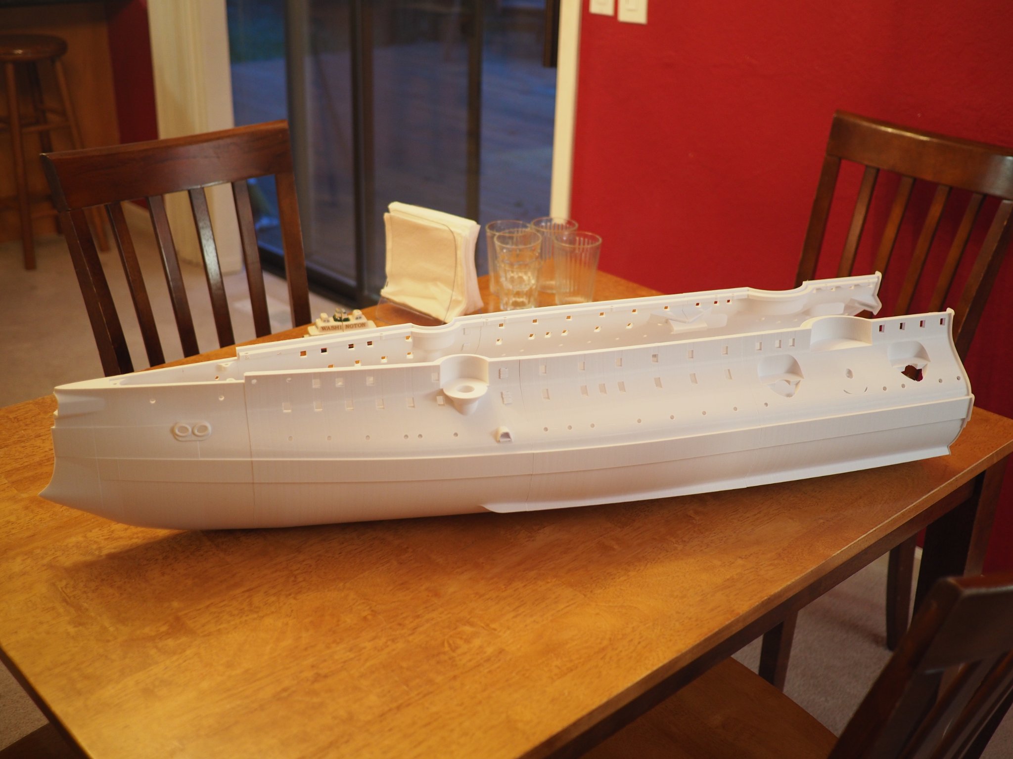
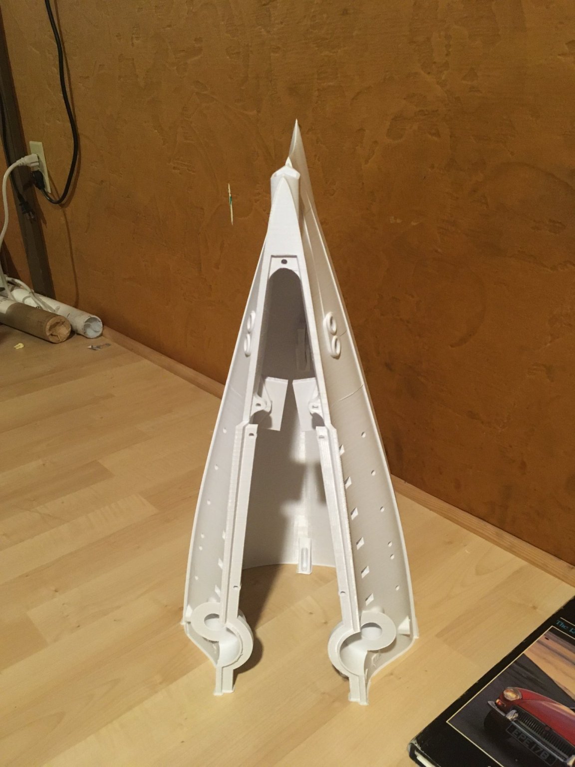
And then I joined the three groups into complete hull.... (I forgot to take a photo but just imagine the whole boat with the bow on the floor and totally vertical teetering precariously against the work bench!) Then once cured and when the Admiral wasn't looking I used the dinner table again for a photo of the completed hull:
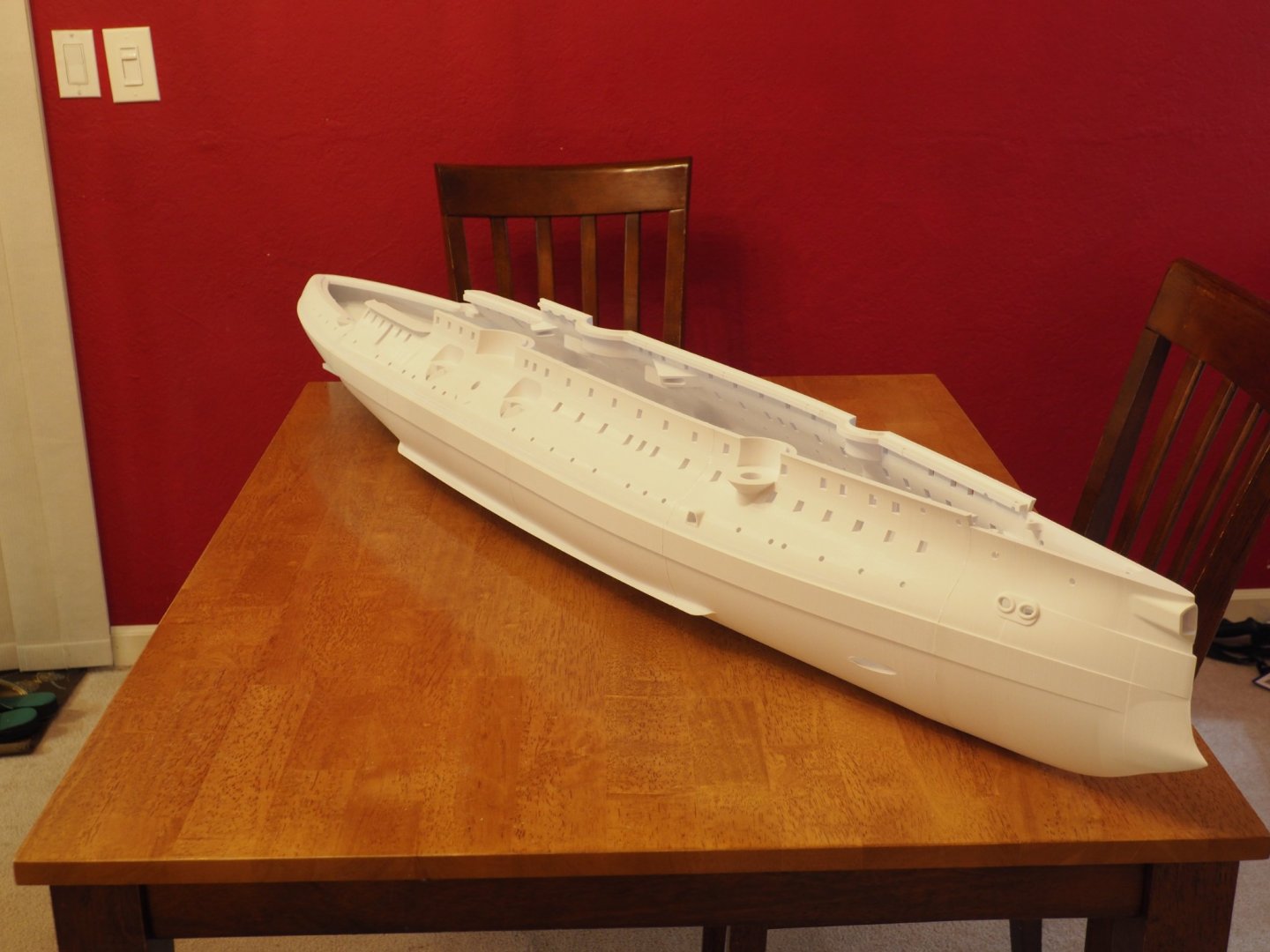
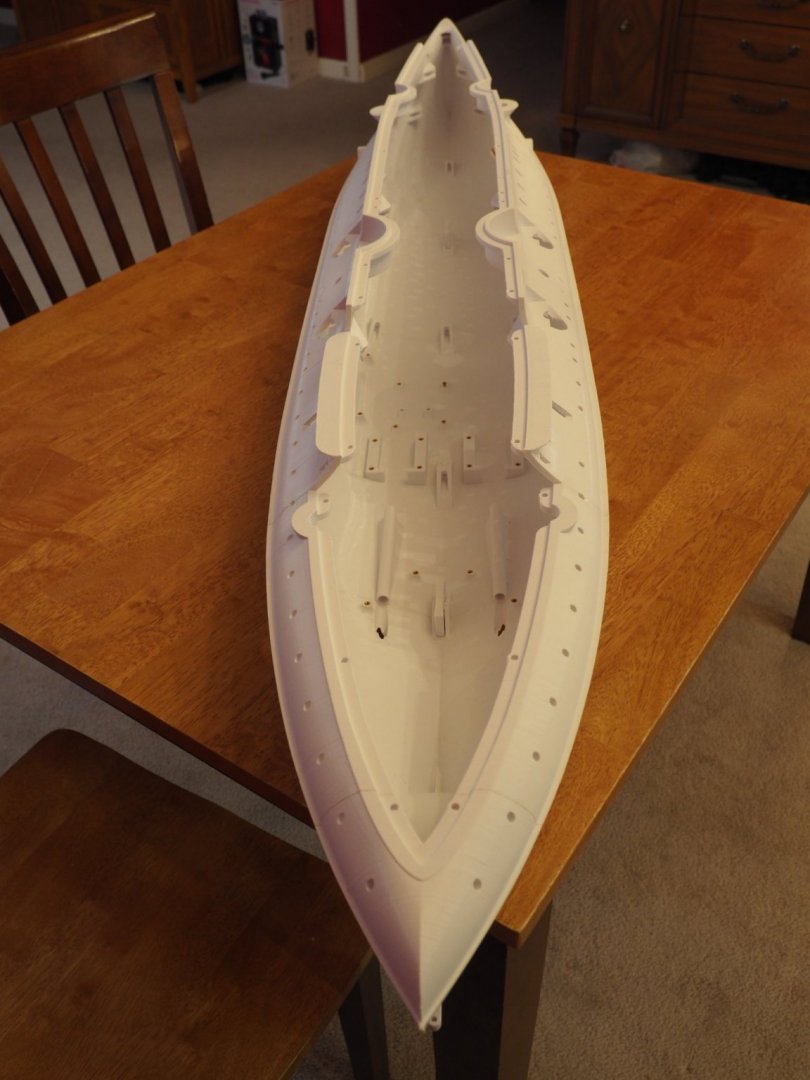
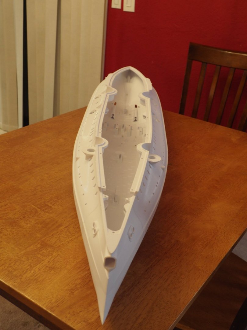
The next step will be sanding the hull to get all the layer lines out and a smoother surface. This can easily be done by hand although there's tricky area's that will need careful attention (more about that later). For the most part a 2" air driven orbital sander will make quick work of most of the sanding. I'll start that after work tomorrow.
-
-
-
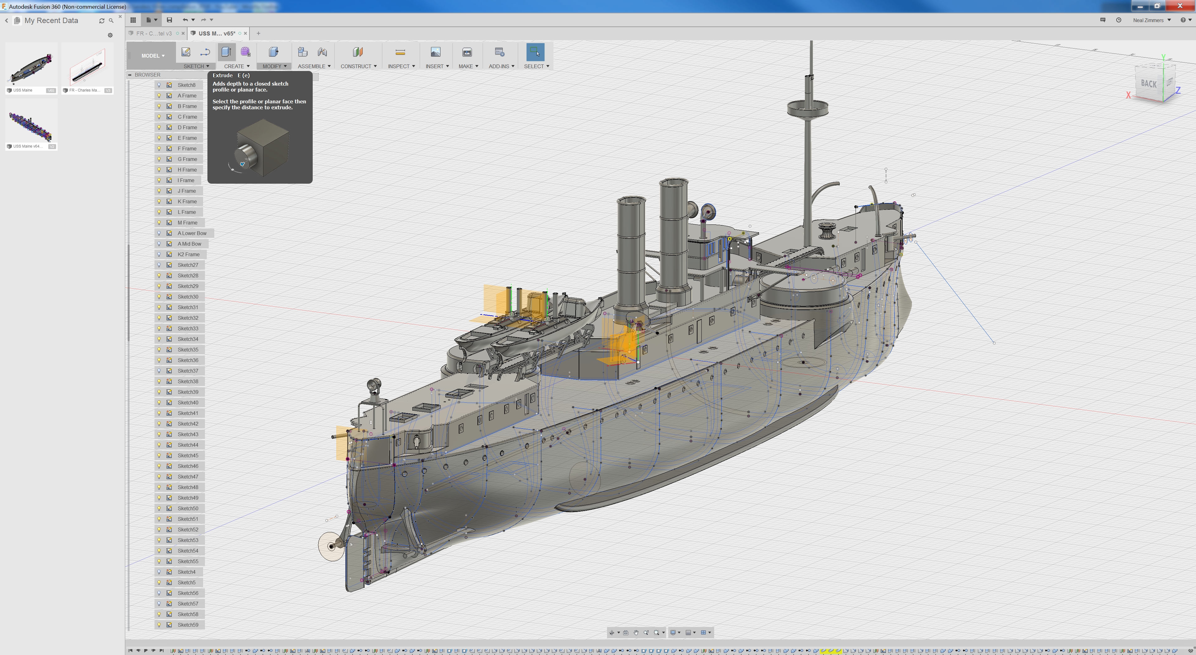
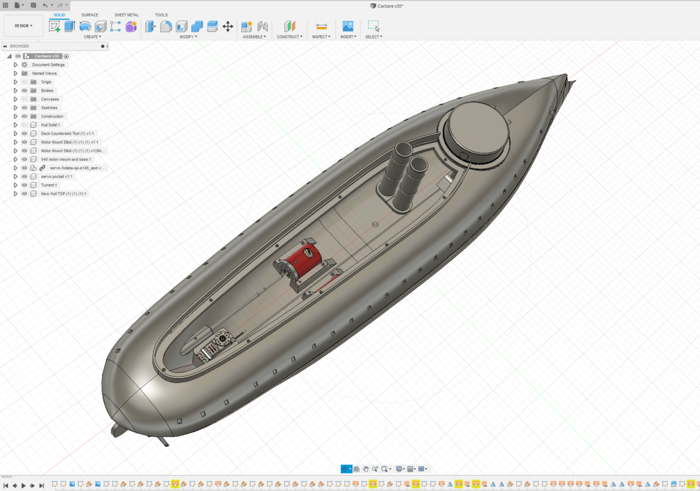
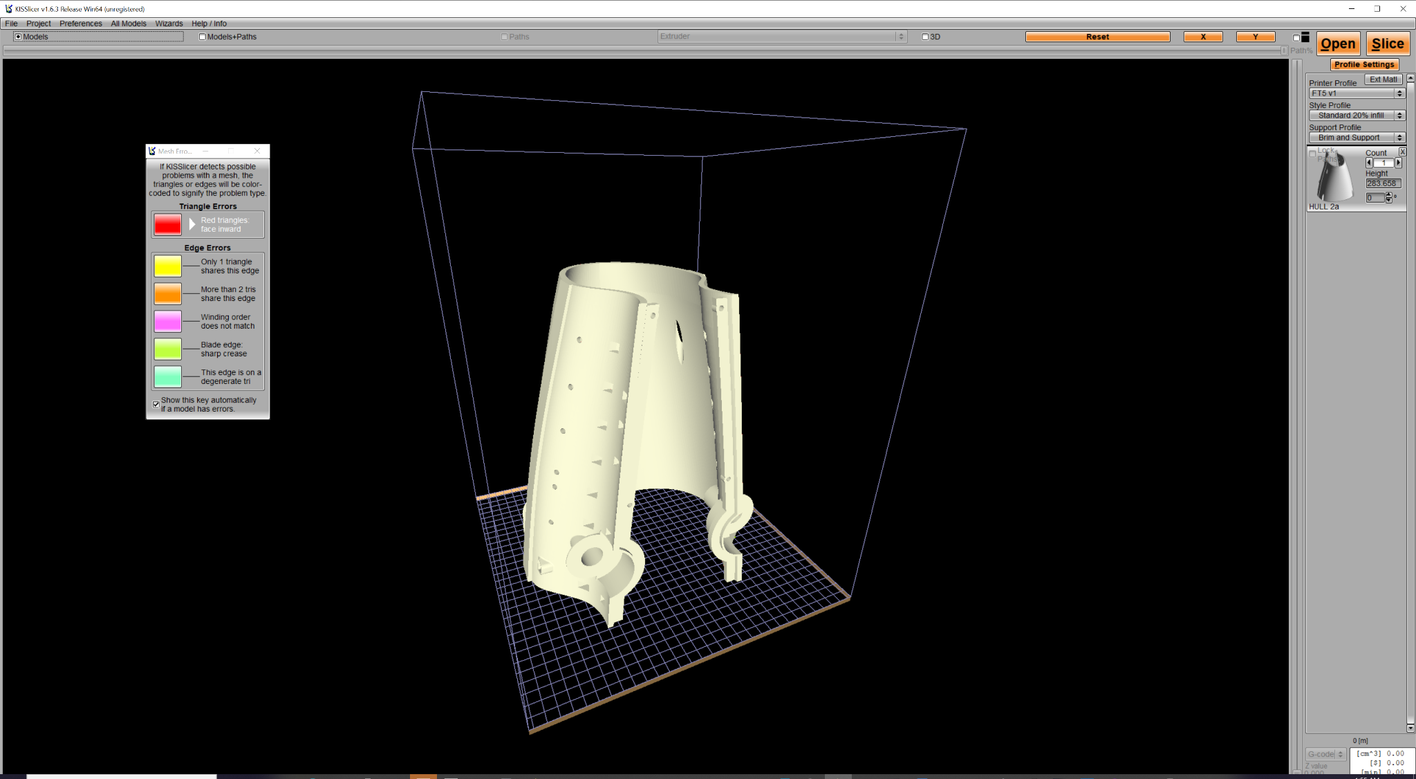
Update - I've been spending the last week or so getting the hull ready to actually print - I've been taking hull and and slicing it up and putting in provisions for stepper actuated turrets. There's going to be 6 hull sections - the longest is the stern at 376mm (which is just shy of 15 inches) and I'm estimating about 18 total days to print all hull sections. While the hull in printing I'll finish up the deck work which is kind of the fun/extremely challenging part since there's really a gap in the plans on the details and will be mostly done by staring at photos for hours on end to get what details I can.
Also, I'm including a link to a video as that might be interesting to some of you.

- mtaylor, GrandpaPhil, yvesvidal and 3 others
-
6
-
On 12/20/2020 at 2:06 AM, Yuuki said:
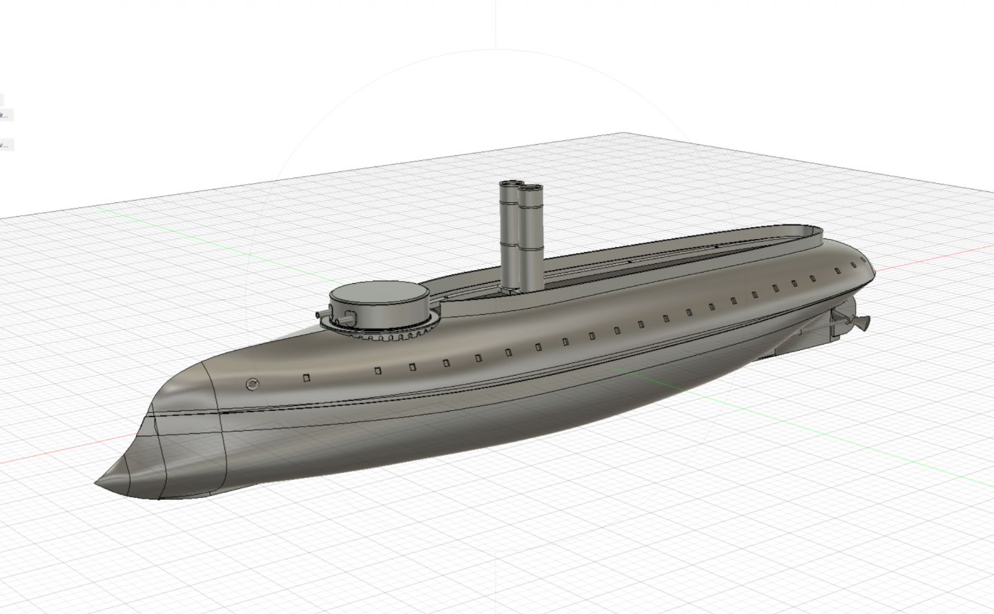
Hi Yuuki, after I'm done modeling the Charles Martel in 1/72 I should be able to go back scale most of the ship down to 1/350 - but I'll probably make the model manifold instead of dealing with 150+ super tiny parts! I already have Messina on my list and other French ships - I'm pretty close to finishing this French ship too:
 On 12/20/2020 at 2:06 AM, Yuuki said:
 -
10 hours ago, Yuuki said:
Love the superstructure, made her a little top heavy but even more beautiful.
I’m sorry I have 0 knowledge regarding modeling softwares, but is it possible to make it a tad smaller to around 1:350 scale?

I have a friend who’s making the Massena in 1:350, if that’s possible having 2 French pre-dreadnoughts on my shelf will make me very very happy indeed :D.
Hi Yuuki, I don’t think scaling it down to 1/350 would work well - some of the features are thin like 1mm so at 1/350 scale that becomes ~0.2mm. It might be possible with a resin printer do you have one of those?
-
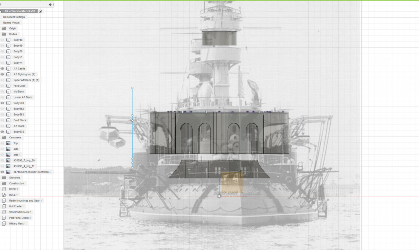
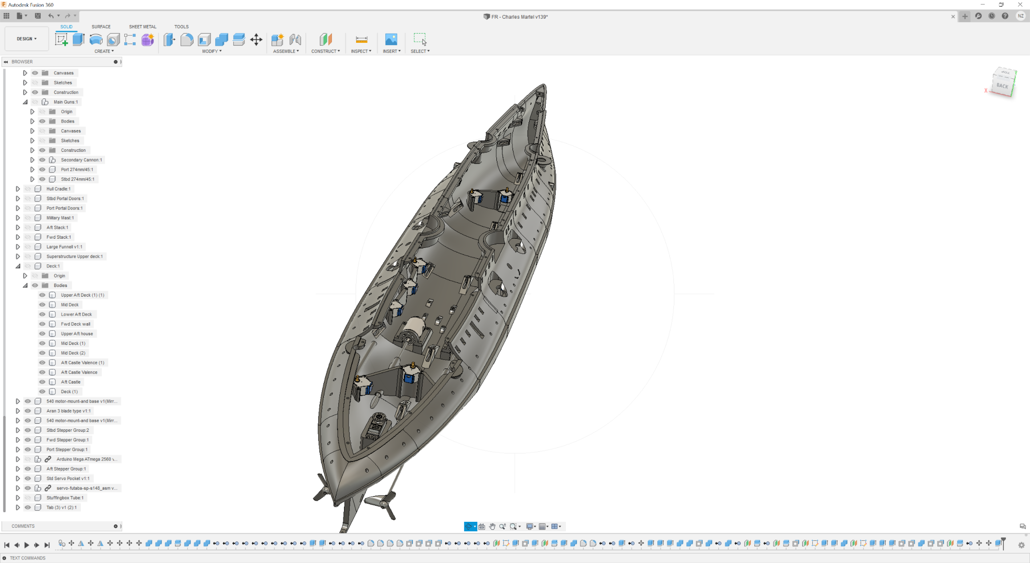
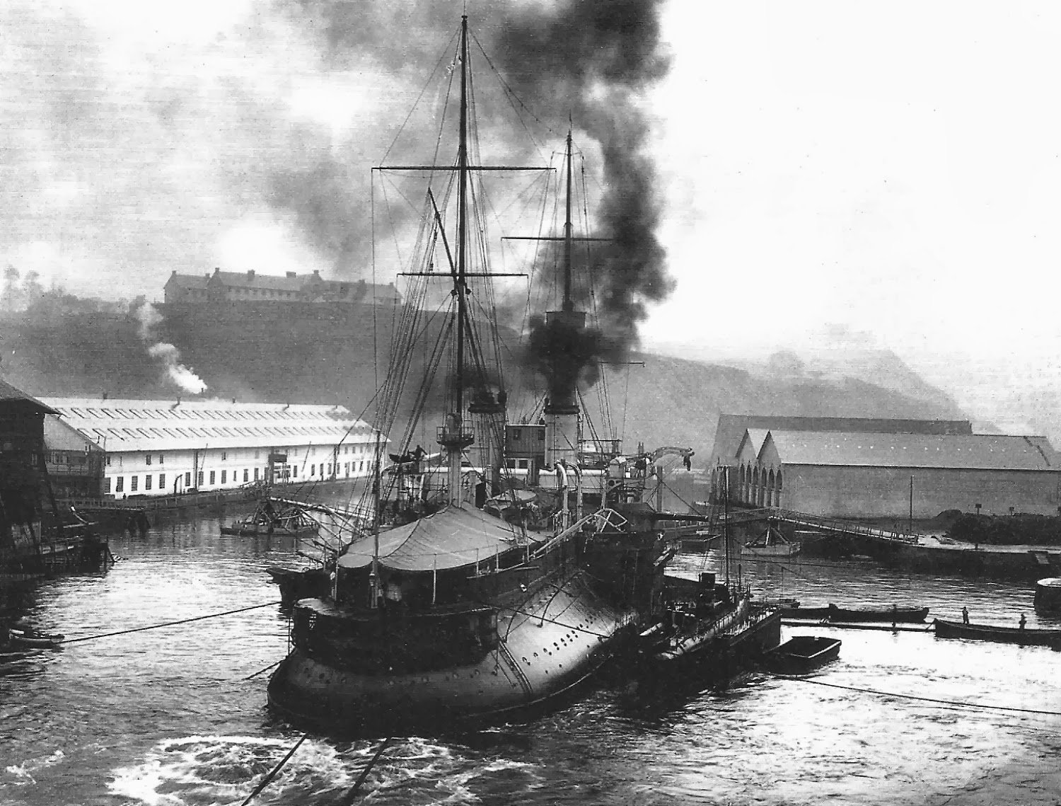
I'm starting to get into the part of the design where I have to lean more and more into what I can what I can understand based on the photos of the ship. There's really very little in the way of the original French designs for the structure above the main deck - sometimes I superimpose photos on the model to get a feel for how really was. I stared at 5 different images for 2 hours looking at the superstructure from different perspectives - there no way I can be 100% sure I'm working in the right direction I just tweak details as I go along and check and double check as I move forward.

-
-
-
-
On 12/7/2020 at 4:47 PM, Roger Pellett said:
If the cross section that you show for Charles Martel above reflects the actual ship she must have had serious stability problems. The circular cross section below the waterline indicates low metacentric height as the center of buoyancy does not move off the centerline as the vessel heels. Worse the extreme tumblehome means that she does not gain righting moment when heeling at larger angles.
Roger
Yes a lot of the French tumblehome designs suffered from a range of stability issues. They added a couple of really tall, really heavy military masts which would have made for some real fun!
- mtaylor, Roger Pellett and Canute
-
3
-
-
Well Done Floyd - BRAVO ZULU!
Photo's look great and I doubt there's another school out there that have a demonstrative tug and barge - gives Mike some real bragging rights 😃
It's hard to really get a feel for the true size of the barge - you have to see it in person - it is truly LARGE.
- mtaylor, fnkershner and thibaultron
-
3
-
Floyd, have you had successful trials with PLA welding? when I tried it I got very inconsistent (bad) results but I may have been spinning up to high -
When you lined up the railing, how big is the difference in the deck height? If you can line up the deck and the hull and the keel acceptably and only have the railing to fix, that would be the way I would go. It's going to be easier to add material/filler and build up a flush surface on the railing than it would be to shave/remove material.
The plastic will hate you from trying to remove more than 1mm of material and it will remind you that the skin is thin, especially in section 5. We could always hang tires over the side too to help hide seam lines
Another alternative is to line up the keel and the hull and the railing acceptably and if you only have the deck that's out of alignment then a sheet of wood or other material + filler could be used to bring the main deck up to match.
- thibaultron, lmagna, mtaylor and 1 other
-
4
-
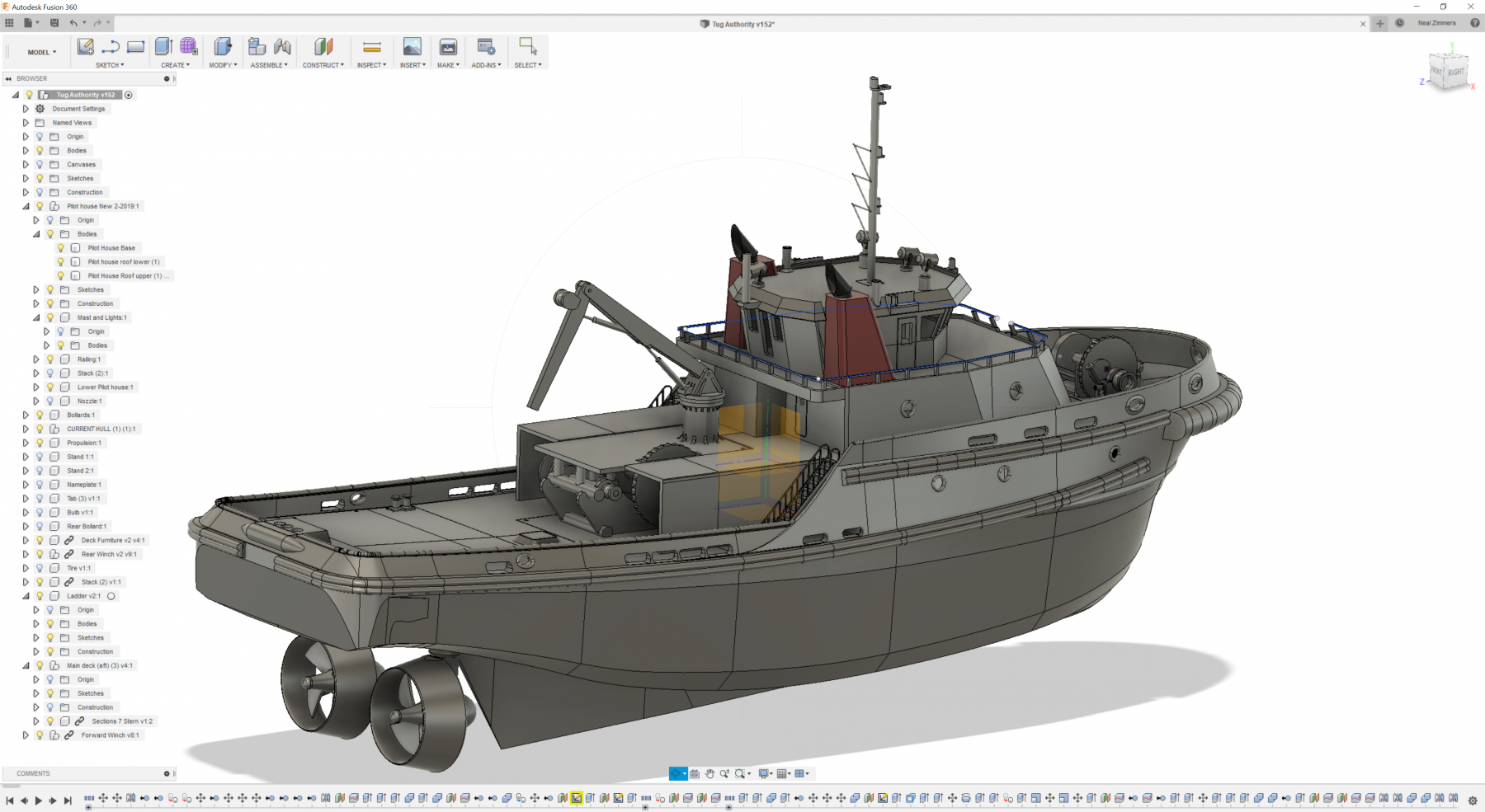
On 3/13/2019 at 6:56 PM, fnkershner said:
So first off, Neal is way too modest. He did all of the CAD design for the Tug, and it was not easy.
LOL I was trying to keep a low profile -!
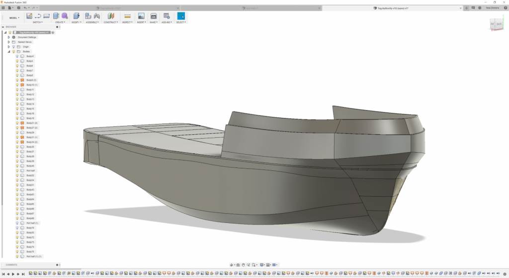
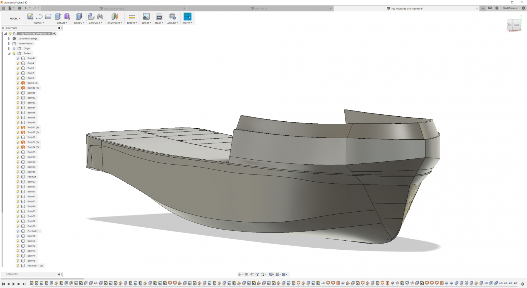
I actually went through 4 iterations of the hull if you can imagine getting 12-20 hours into something and going "nope, not gonna work". I'm including pictures showing versions 1,3, & 4
- version 1 was some experimentation I did when it looked like all we would have to go on was 7 photos of low quality- version 2 had only a few partial frames to work with and no general arrangements - gleefully deleted cause I hated it so much which is why I can't show it
- Version 3 we had gotten just maybe not quite enough and I had to leverage some schematics of a similar tug to get there.
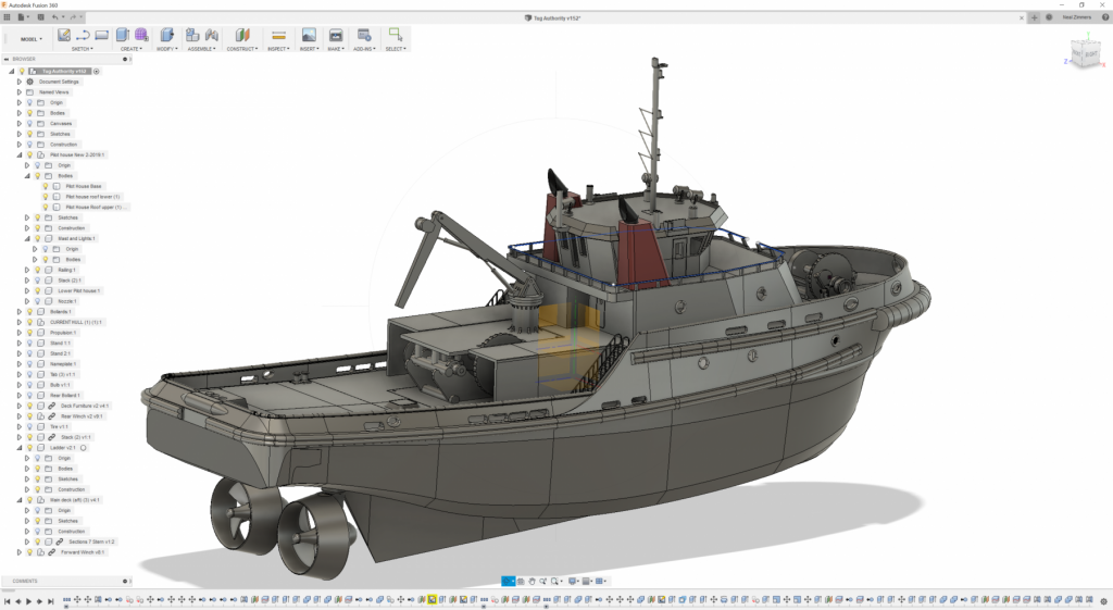
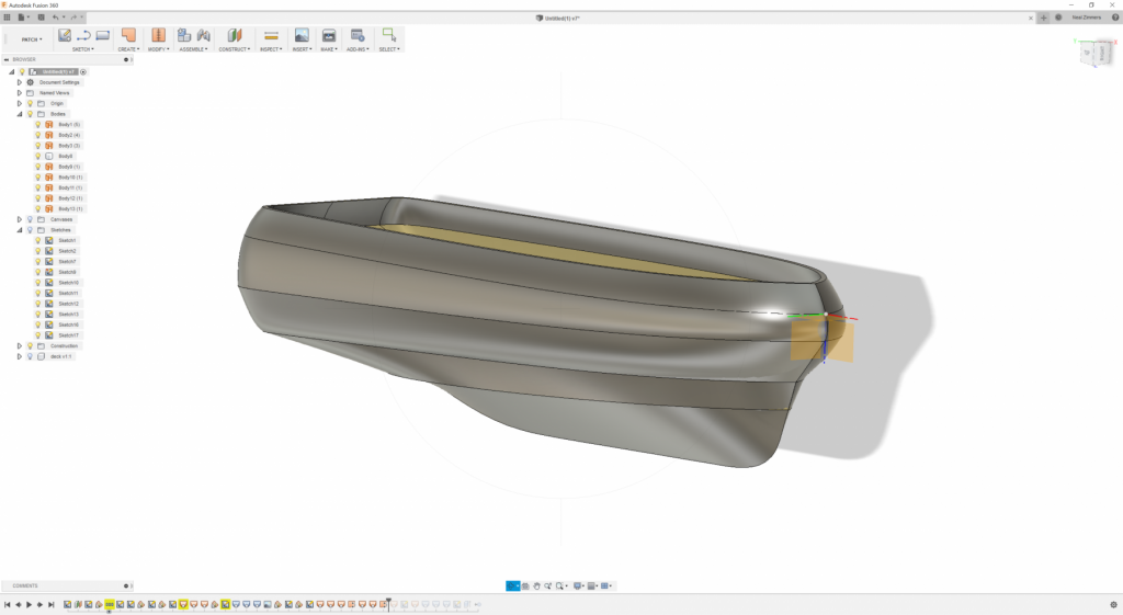
- Version 4 was completed using about 20% of Version 3 and about 60 photos from an on-site visit of the tug which turned out to be critical in completing the design
The promise of 3D printing boats (or anything else) are perfect parts, that fit together perfectly, perform and look perfect.
- Unfortunately there are multiple realities (some of them good, quite a few of them bad) when you actually attempt it because the printing part is experience, skill, and science driven - but I don't think that's different than any construction technique - I remember building a FW 190 out of balsa from a Gillows kit in highschool - glued it all together perfectly but the balsa was green and when it dried overnight the fuselage was bent like a banana - totally unusable.
For me - I'm all in on 3d printing - probably because I can do all the design work, planning, and integration of elements which is a very pleasing part (and I do okay with the printing quality!)
- GrandpaPhil, lmagna, BenF89 and 6 others
-
9
-
10 hours ago, BenF89 said:
Thanks, that makes good sense. I wondered if easy removal was part of it, for transportation or some other reason. Easy reinstallation is just the flip-side of that. I assume these are ‘high strength’ enough so it doesn’t get knocked off easily? How thick is the plastic between the magnets? And, how are they attached to the plastic? (Sorry for the ‘20-questions’ - I just think it’s a cool idea.)
Hi Ben,
The way it works is actually only 1 magnet (neodymium) down at the bottom of the hollow column (basically a pipe), the base of the water cannon has a step in that narrows down the end to fit into the column but at end of it is a steel screw - steel screw contacts and is held in place by the 5mm magnet - two magnets might work but the steel screw is adjustable ensuring proper contact.
-
4 hours ago, BenF89 said:
Looks great! Just curious- what is the advantage of using magnets for the monitors? Just so they are free to be manually aimed as needed?
Hi Ben, I contributed to the project a bit - the school wanted certain features and one of them was for the nozzles/water cannons to rotate - and the thought is the magnets would allow for the 360° rotation while also being easy to replace should they get snapped off by enthusiastic students. There's a couple of other components that were made to allow for removal and replacement (pretty much anything that was going to be actuated or manipulated by hand).
- thibaultron, BenF89, druxey and 3 others
-
6


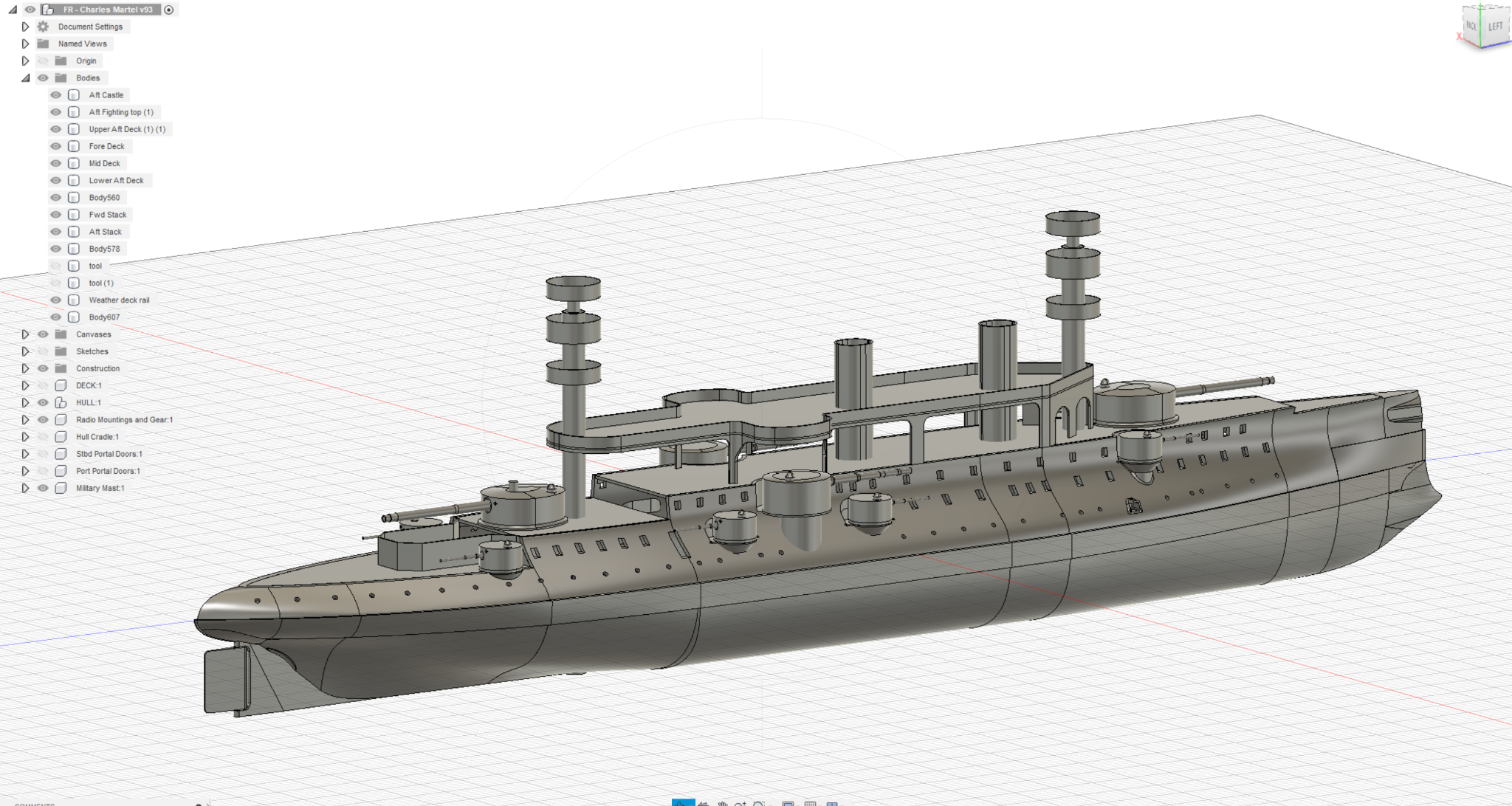
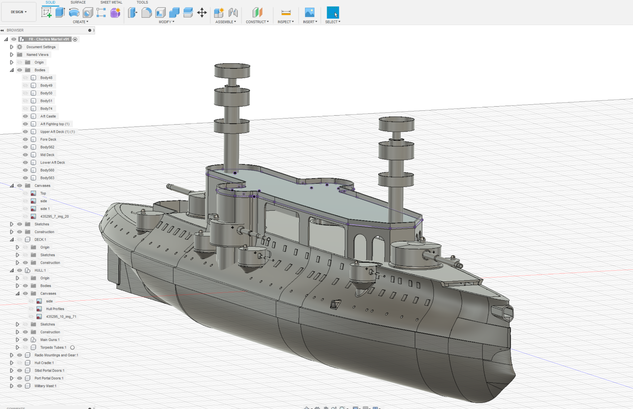
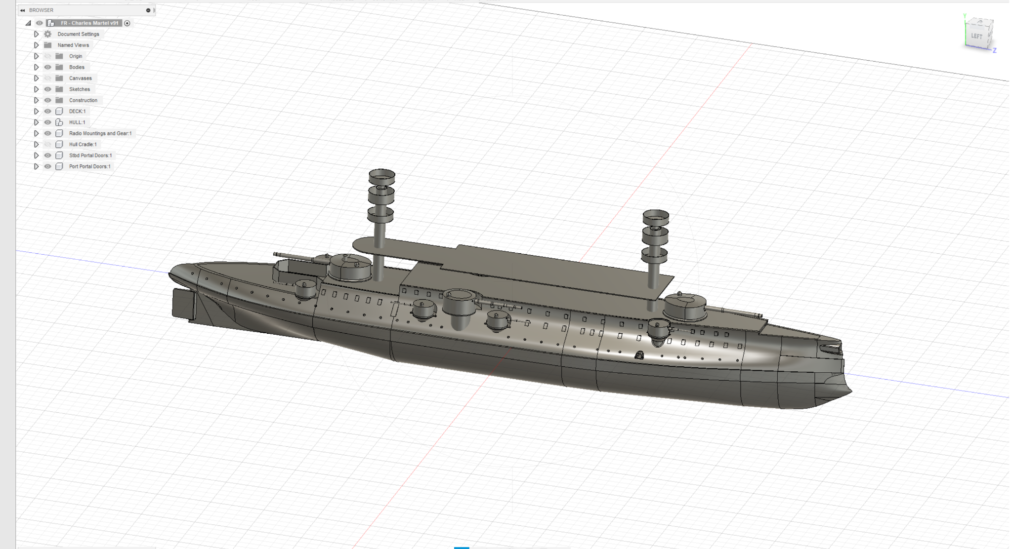
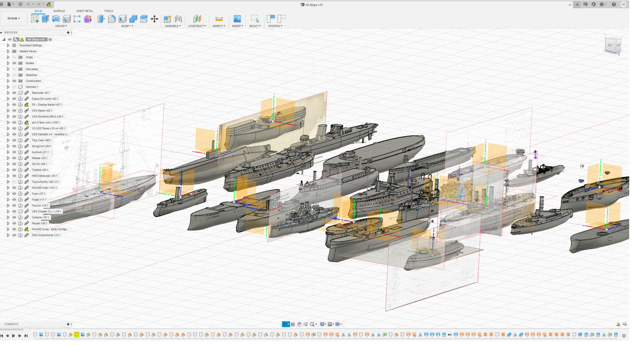

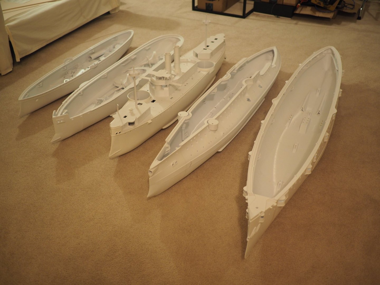
French Battleship Charles Martel by Haze Gray - 1/72 scale - Radio (plastic 3D printed)
in - Build logs for subjects built 1851 - 1900
Posted
Sure here you go - 5 hulls but the one with the superstructure and funnels is the USS Main - that hull has been sanded and partially painted - I actually have a 6th hull printing that is not in the photo (for the USS Texas - the original one from the 1892)