


shipmodel
-
Posts
904 -
Joined
-
Last visited
Content Type
Profiles
Forums
Gallery
Events
Posts posted by shipmodel
-
-
Hello to all in this strange time –
And thank you if you have followed me here from my last build log of the USS/SS Leviathan
I apologize for the long delay between the end of the Leviathan build log and this, and also that It will also not be as detailed as my last write-ups. I will point out some building techniques that are a bit different from former ones, but for the most part it is more of a tour of the completed model than a blow-by-blow description of the construction.
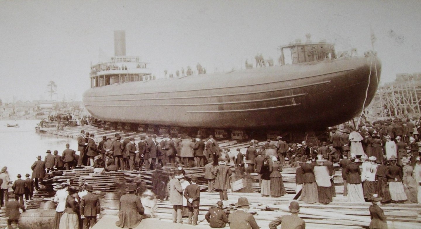
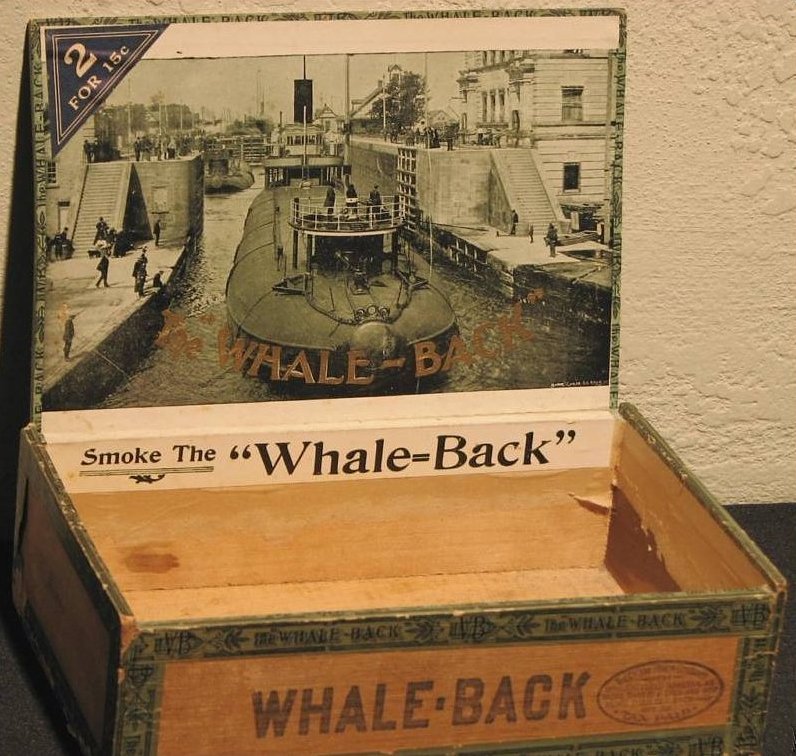
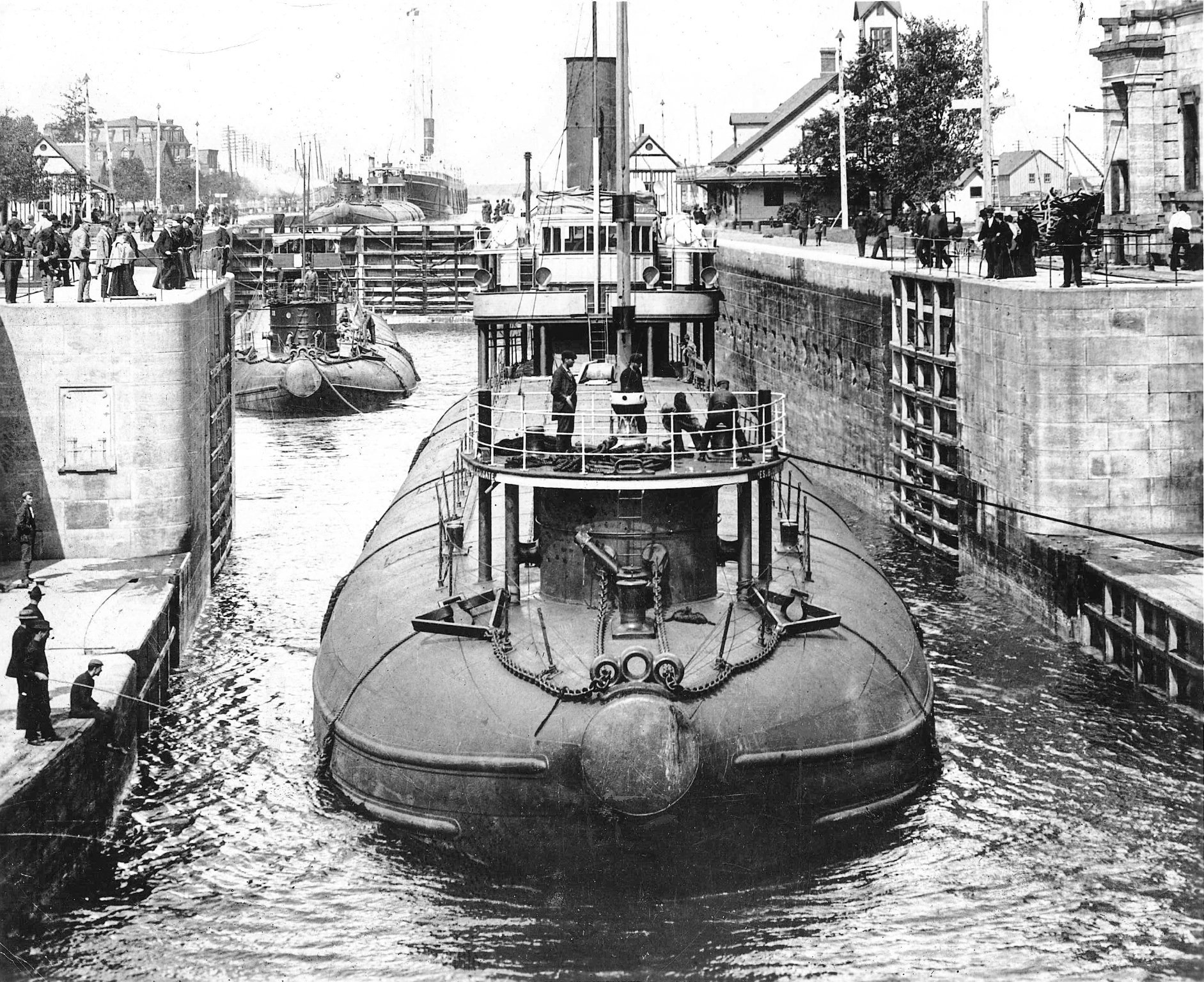
This is the second of seven models for the US Merchant Marine Academy museum. The subject is the whaleback steamer James B. Colgate, built in 1892. Designed by Capt. Alexander McDougall, these boats were a major departure from accepted ship design. Rather than sitting high on the water these boats rode, when loaded, with little of the ship above the waves. The idea was that, like a floating log, it would let rough seas pass over it rather fighting them.
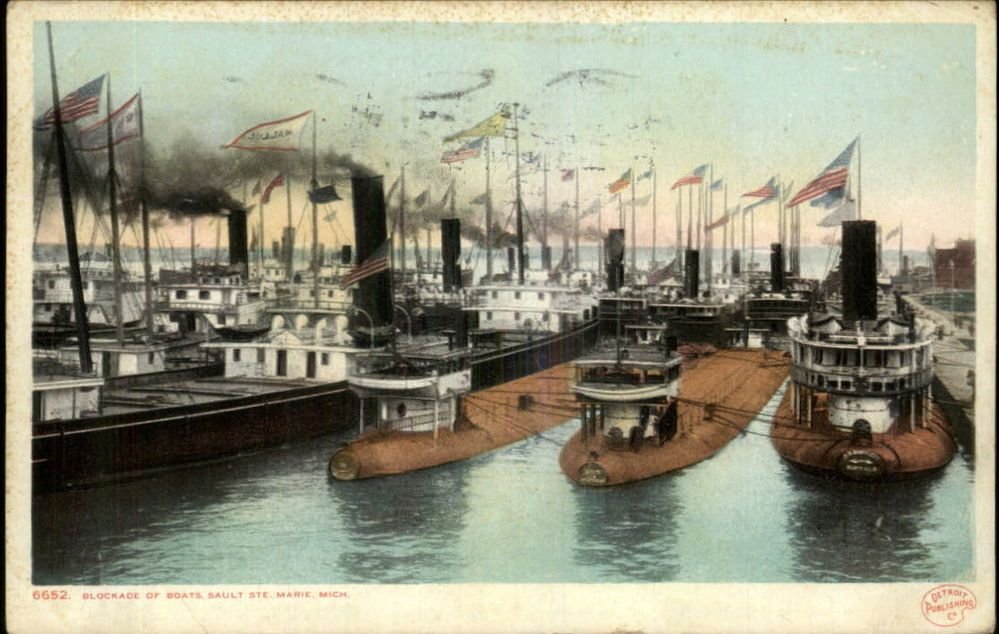
As an aside, the postcard above, titled “Blockade of Boats at Sault Ste. Marie,” commemorates a significant moment in the history of shipping on the Great Lakes. On September 5, 1899 the 500 foot long bulk cargo steamer SS Douglass Houghton was towing a barge named the John Fritz. Both were owned by John D. Rockefeller and together were loaded down with 15,000 tons of ore. The Houghton lost control and came to rest completely across the navigation channel leading to the Soo Locks, the bottleneck between Lake Superior and Lake Huron. Unfortunately the size of the ship made it nearly impossible to free her and the entire volume of shipping traffic through the locks, greater than at any other point in the world at the time, came to a standstill. It was not until five days later that divers and engineers were able to free her by dynamiting the banks of channel. By then more than 200 ships, many of them the largest in the world, were sitting idle. There were so many that when the blockade was finally cleared the line of ships moving single file through the gap was more than 40 miles long. The event triggered hearings in Congress and ultimately led to changes in the administration and maintenance of the inland waterways of the United States.
The whaleback design proved surprisingly successful and 43 barges and steamers were built between 1888 and 1898. Although there may have been little of the hull above the waterline, like an iceberg there was a lot more below that the eye could not see.
McDougall designed them around the new triple expansion steam engine that used 40 percent less coal, yet could still drive them along at 14 knots, very speedy for bulk carriers at the time. Twelve large hatches opened into a large cargo hold which could be loaded quickly from automatic conveyor belts. The design was finally supplanted in the early 1900s by much larger ships which could weather the large winter storms (the example of the Edmund Fitzgerald notwithstanding).
Despite their commercial success, the whalebacks were not popular. The design was too radical, and was resisted by the old guard. They were also not very attractive. The upturned bow with its round stubby front plate may have helped the boats to skim over the water, but earned them the nickname “pigboats.”

The Colgate was a typical whaleback steamer, 308 feet LOA with a beam of 38 feet. She carried up to 3,500 tons of cargo in her hold, usually iron ore or coal. A small round deck house at the bow handled the anchor machinery and helped with navigation. On the roof of the deckhouse were several bollards and fairleads for the mooring lines. The midships hatches, as designed, had flush covers that had to be bolted down individually. A later modification had raised coamings which were easier to operate.
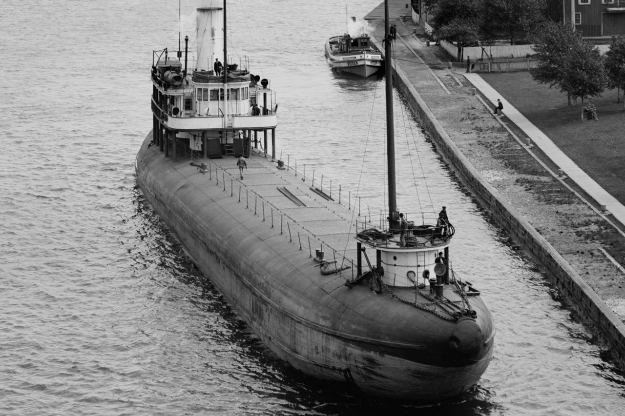
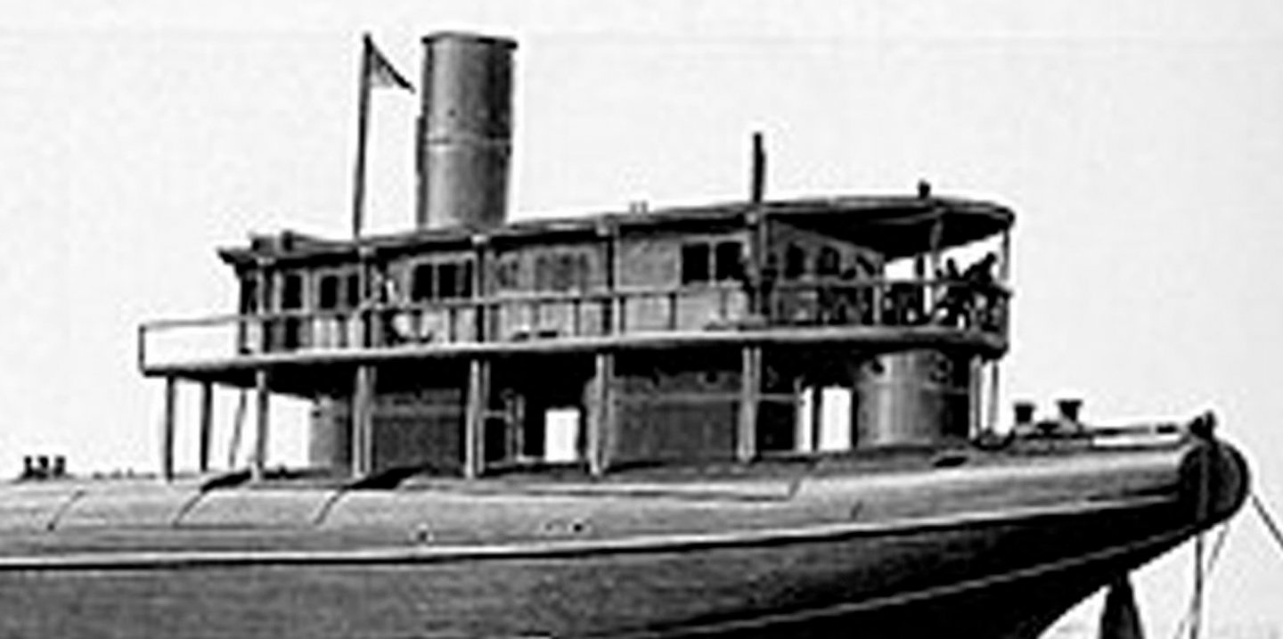
At the stern was a much larger two-story deckhouse which contained the bridge and some small cabins on the upper deck. These were supported by three round structures similar to the bow deckhouse, designed to allow large waves to flow around and between them with as little resistance as possible. Despite these design innovations the Colgate was lost, with four other ships, in the large ‘Black Friday’ storm on Lake Erie on October 20, 1916. 25 of her crew of 26 were lost, with only the captain surviving.
So, after a full 24 year career of productive and profitable service, the Colgate is remembered as an example of radical marine design that was successful for a few decades, and as an icon of Great Lakes memorabilia.
Next time, research and construction begin.
Thanks for looking in, and stay safe and well.
Dan
-
Hi Marc -
Excellent work on the QG base and details. Those compound curves must have been a bear to get right.
Stay safe and Happy Thanksgiving.
Dan
- Hubac's Historian, druxey, EJ_L and 1 other
-
 4
4
-
Hi Toni -
It's always a delicate matter to raise what may (or may not) be a mistake by another modeler. I usually hold my tongue unless the issue can be resolved quickly and relatively easily. I am glad that you had not gone too far before changing direction. I'm also happy that the final solution will actually be easier than before.
Looking back, you may have been confused between the look of bolts and clench nails. Both were used in the construction of lapstrake hulls. The clench nails had broad heads, went through the planking, were fitted with roves on the inside and were hammered from both sides like a rivet. Bolts went through more substantial timbers and had washers on both sides to prevent overtightening. The final exterior look of a bolt fitted this way is very much like a clench nail with a rove on the outside.
As well as the articles mentioned by Druxey and Greg, you might look at a thin booklet called "Clenched Lap or Clinker" by Eric McKee and published by the National Maritime Museum in England. I'm pretty sure it is available for not a lot of money.
Great work nonetheless.
Be well
Dan
-
Hi Toni -
You've achieved a really nice solution to a tricky problem.
When I tried to make metal foil roves I completely failed and fell back on paper saturated with glue.
It was for the Gokstad ship, so the roves would have been iron in any case.
I could not tell from the photos. Are the roves on the inside or the outside of the hull?
Great work. Thanks for sharing.
Dan
-
Hi Charlie -
Just got back in the city on a semi-permanent basis. Unpacked, refilled the pantry and fridge, and got a chance to look through MSW. You have certainly made a lot of progress, and all of it quite nicely done. Bravo. The planking and trenneling came out particularly well.
I like the copper tape too. I made the impressions from the back side, through the paper, so they made positive bumps on the face of the tape. Then I burnished the bumps back down so the final look was of a flush circular blemish, which looked a lot like the flatheaded nails that were used.
I'm wondering what yours will look like if you burnish the face of the tape. Might be an improvement over mine.
Here's a toast to an effective vaccine in the very near future so we can start up club meetings again and I can see your stuff in person.
Stay safe and well
Dan
-
Beautiful work, Marc -
I really like how you achieve the look of wood on the plastic.
It's truly hard to tell that the decks are anything other than individually laid planks.
Stay safe.
Dan
- popeye2sea, druxey, EJ_L and 4 others
-
7
-
-
Hi Marc -
Frustrating work, I can see, but the results are stellar.
I plugged in "Tamiya paint retarder" and Amazon came up with a 40ml bottle for about $9. It says it is for acrylics, but I have no idea how or how well it works.
Stay well
Dan
- EJ_L, Hubac's Historian and mtaylor
-
3
-
Hi Marc --
No guess as to the number of different structure/detail/rigging choices I might have made. There are a bunch, though, especially if you count each individual gunport lid.
I tip my hat to Piet for even trying to quantify them.
As for rigging, the book by R.C. Anderson, The Rigging of Ships: in the Days of the Spritsail Topmast, 1600-1720 (Dover Maritime) , available from Amazon for a few bucks, was a godsend when I was rigging the Sovereign of the Seas and the Queen Anne's Revenge. He presents not only the basic English style, but also shows how French {Continental} practice differed. I took it a page at a time and tried to understand each line before moving on to the next. It was slow going, but working from the gammoning up and aft it was doable.
If I haven't said so before, that figurehead looks great.
Dan
- Hubac's Historian, mtaylor and EJ_L
-
3
-
Hi Marc -
Well thought out and analyzed. The head structures should come out well with your excellent level of persistence.
I do recommend that you fill the gammon holes at this time. The kit ones are much too level, I think, and probably mislocated.
The holes should angle up and forward, much like the ones in the St. Phillippe drawing. (The ones on Marc Yeo's model are, I believe, too angled.)
I found it nearly impossible to locate and angle the holes on my models until the headrails were planned out precisely, or even until after they were installed.
The holes should lie just under and parallel to the lower edge of the lowest headrail. My old eyes think they see them in this location in the drawings.
This gives the greatest radius of curvature for the gammoning, and therefore the least strain on the ropes as the ship works in high winds and seas.
The holes are angled so the gammoning turns press against each other as they are laced, starting from the aft (lower) end on the bowsprit to the forward (upper) end of the hole.
And yes, this does mean that the turns cross over each other, a detail that is hidden by the final frapping turns that tighten them, which explains some of the confusion.
You can always reopen the holes if you find that they are correct and I am wrong. (Perish the thought . . . LOL . . . )
Dan
- druxey, Hubac's Historian, mtaylor and 1 other
-
4
-
Can't go wrong with Daryl - - -
If I say she has a beautiful body, will she hold it against me?
Dan
- mtaylor, Hubac's Historian, EJ_L and 1 other
-
4
-
-
Hi Marc -
If I understand your problem, there is a geometric solution using a fan-shaped set of lines.
I would love to include a drawing, but I don't have access to my library, and I am stumped, at the moment for its name (another senior moment).
I am sure that it appears in either Roberts' or Dressel's books on planking.
Maybe you already know the trick. If so, ignore this.
Here is how I make it, sorry if it's a little long.
On graph paper I draw an X-Y pair of lines with their intersection toward the left of the page. I draw another vertical line set some convenient distance away to the right.
On the vertical line I make equidistant marks up to as many, or more, than the planks I expect to need.
A set of lines from the intersection go to each one of these, making a fan shape.
Now any similar vertical line will cross those fan lines an equidistant space from each other, no matter how tall or short.
Lay a strip of paper on the fan and mark off the divisions that match the space you want to fill and the number of planks you want.
Lay the strip on the deck athwartships and mark out your plank widths.
As a possible addition, increase the space for the king plank location on that initial vertical and it will always be proportional to the planks.
I have not done this and it may not end up looking like you want.
If you are still doing research, you should look for 'coamings' rather than 'combings'. They sound alike, but are very different animals.
Stay safe and well.
Dan
-
I'm with Druxey on this.
In fact, when carving a figure, either human or animal, I start with the eyes.
Nothing sets the tone and realism like them.
If I get the eyes wrong, I always discard the piece.
Dan
-
Thanks, Marc -
This is a really useful tutorial on miniature carving and should improve the work of everyone who reads it.
Looking forward to seeing how all your many intricate carvings come out.
Dan
- Hubac's Historian, EJ_L and mtaylor
-
3
-
-
Ron -
You have my most sincere sympathies. Been there, done that, - - thrown the results across the room . . .
I saw in an earlier photo that you are using a mini-torch to do the heating.
I never liked the one I have. Like you, I had a lot of trouble localizing the melting.
Now I use either a resistance soldering unit (Cold Heat) or a small soldering iron used for the electronics industry.
It takes a bit longer, but I have much more control over where the heat is and where it isn't.
A wet piece of folded paper towel is all I ever need to keep the heat from travelling too far.
Best of success.
Dan
-
Hi Marc -
Happy to be of some small help.
The wood is, if I remember, apple.
I used to use a handheld drill as a lathe before I got the benchtop drill press.
I set up a piece of wood with a conic depression in it to steady the free end of the dowel as it turned.
This does require that either the drill or the wood, or both, need to be clamped in place.
Or you will need three hands.
Dan
-
-
Thanks to all who contributed to this interesting discussion of the whipstaff. I thought I was pretty well versed in its intricacies, but even so I have learned a lot.
At the end, I have to agree with Druxey and Dafi that any slot in an upper deck, if needed, would be fairly short. It could be covered, railed, or even with a hood.
The one reasonable certainty seems to be that a long slot, as drawn by Leminuer or Budriot, would not be needed.
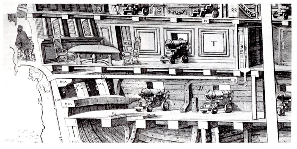
As far as contemporary cutaway drawings go, they are so varied and all over the place that only very general conclusions can be drawn. For example, below is one which my notes identify only as "Phillips - 1690s" It has a very short staff that does not pierce the upper deck at all. Others show the mizzen mast being stepped on the deck above, with the tiller passing under it and extending forward to meet the whipstaff. In that case the pilot's view and communication would not be hampered as much, but the mast might not be as stable. As with many of these issues, I think that shipwrights experimented with various solutions in different ships, so there is probably no one clear 'right' answer.
Of course, I could also be completely wrong. 😕
Thanks again, and stay healthy.
Dan
- mtaylor, BLACK VIKING, J11 and 4 others
-
7
-
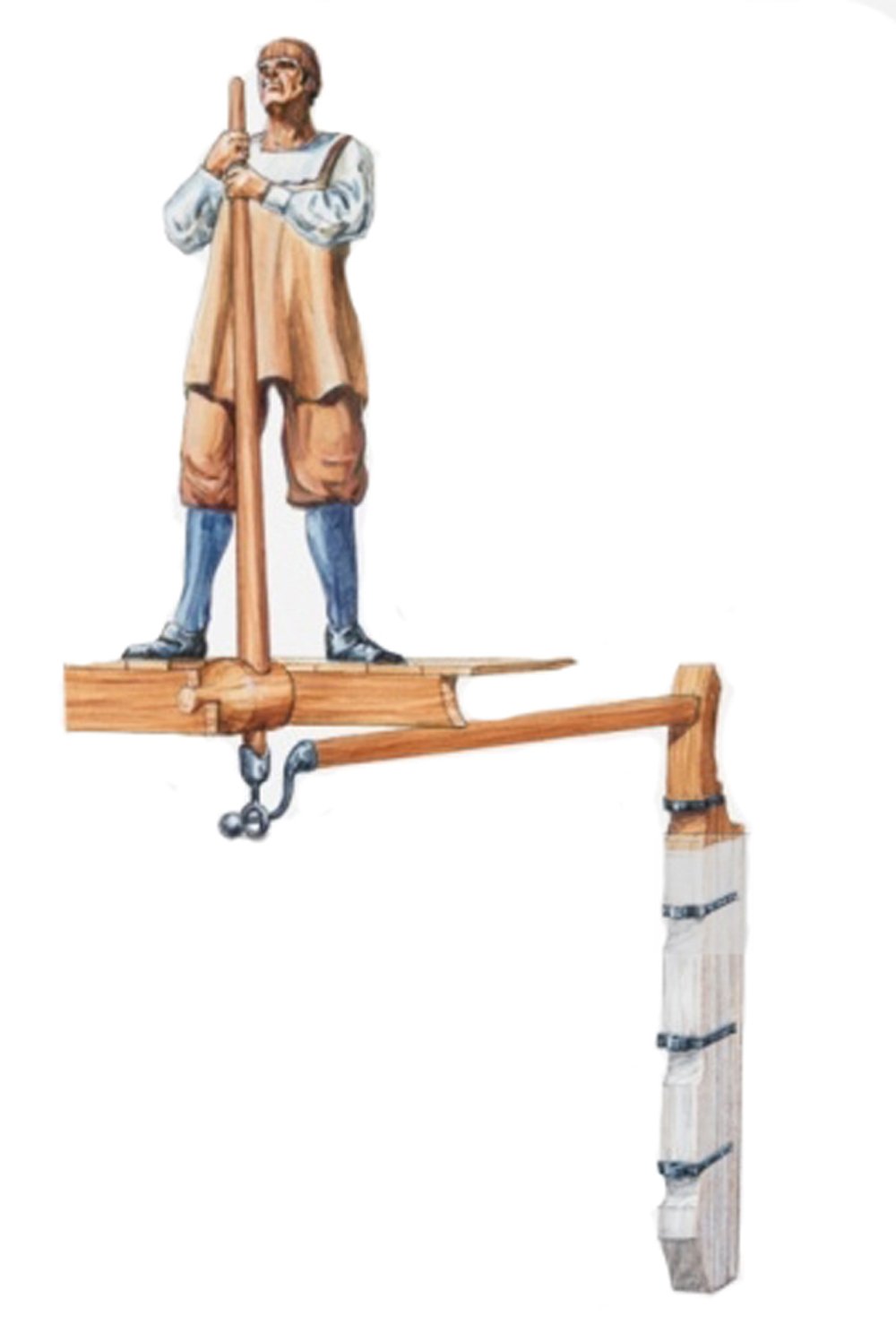
Hi Dafi -
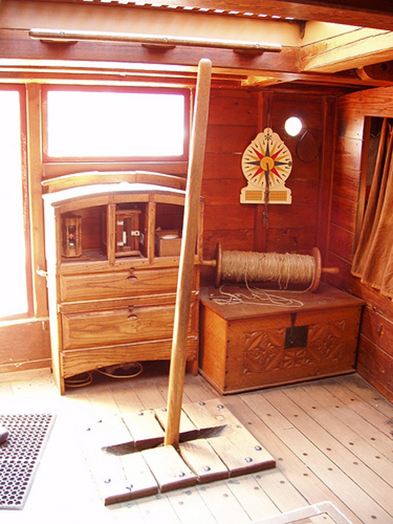
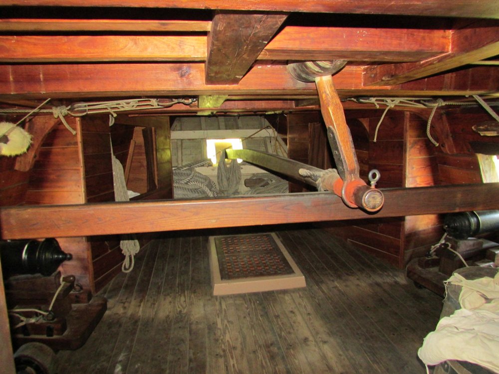
Your point is well taken. In a large ship or in rough seas it may have been necessary to have more than one handler (helmsman, pilot) for the whipstaff, and a longer staff would give room for them to work together. In my illustration I took the drawing from Goodwin just to show how the head of the staff moves in as much as it moves down, I did not really consider overall length other than to question the need for a long slot in the deck above. As for length, below is a photo of the top of the staff for the Susan Constant, which matches the below deck picture from my earlier post. I know that she was a much smaller ship, but the staff only looks to be 5 or 6 feet long. This agrees with photos of whipstaffs from other recreations, Batavia, Kalmar Nykel, and Mayflower. I have a photo of the highly elaborate rowle from the much larger Vasa, but not the top of the staff, so I can't say how long it was. Perhaps someone knows.
As far as the William Rex model - with all respect to the modeler, he has the staff coming up through a simple hole in the deck above, which is unworkable.
Dan
-
Jan -
I think we are agreeing in different words. The overlength staff doesn't give more leverage, since the force applied by the helmsman is all athwartships due to the rotation of the rowle on its fore/aft axis. He pushes the head of the tiller to the side by sliding the staff through the rowle, he does not lever it aside. The mechanical advantage is gained by the ratio between the length of the tiller and the width of the rudder. Nor is a longer staff needed to enlarge the arc that the tiller head travels. The swing of the tiller arm is limited by the length of the metal crook or the end of the tiller that the ring on the base of the whipstaff slides down as the helm is put over. When the ring reaches the end button no further movement is possible. The lower photo is from the Susan Constant reconstruction.
I went to Google and searched for William Rex. I found many images for the very large model in the Rijksmuseum, but none of the deck with a slot in it. Can you point me to a photo?
Thanks
Dan

-
Hi Marc -
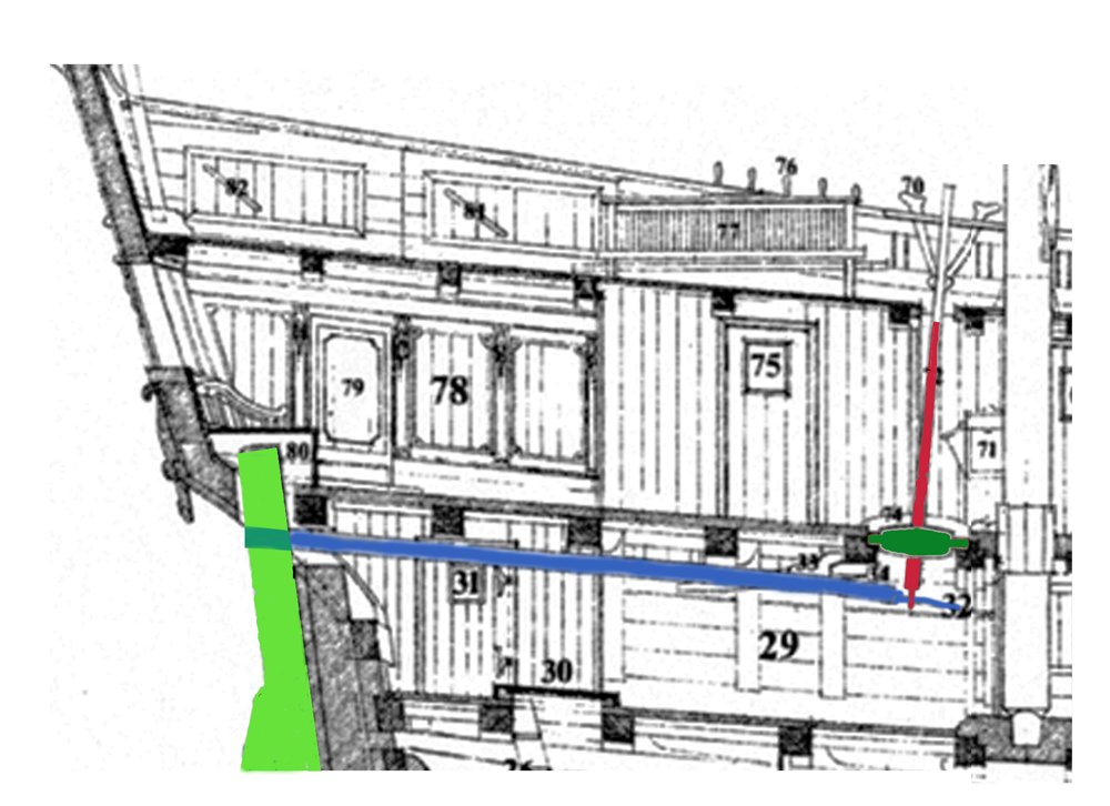
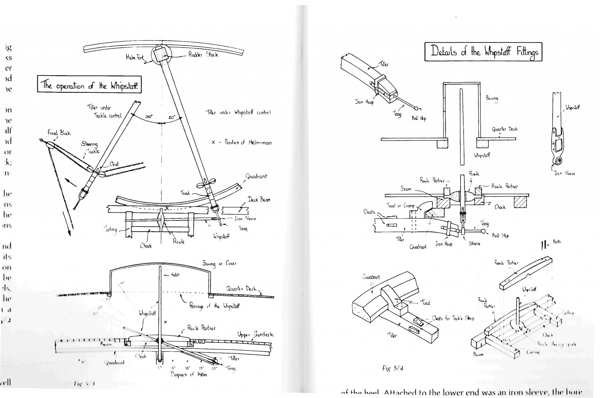
The whipstaff question is one that I worked on for a while. I have never been happy with the long slot in the deck above (#97 in your illustration). It would weaken the deck and introduce a tripping hazard. If there is such a slot on a contemporary model I have not seen it. Moreover, it is, I believe, completely unnecessary. Here's why -
I took contemporary illustrations as well as the measured drawing from Goodwin's "Arming and Fitting". Then I took out various parts using Photoshop and laid them in various positions to see how they related to each other as the whipstaff pivoted, the tiller arm swung, and the rudder turned.

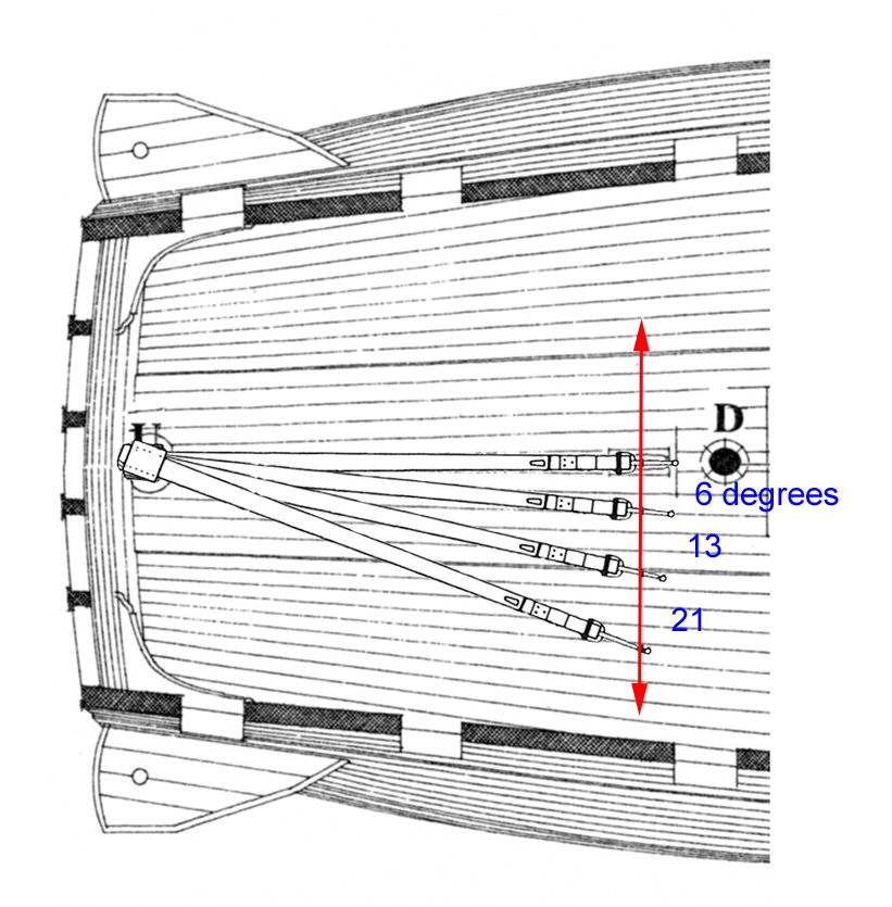
Notice that, as you can see in the Goodwin drawing, the whipstaff is not fixed to the rowle that it pivots in, but it slides through the hole in the rowle so it can reach the end of the tiller arm as it swings side to side. This is the key to my thinking.
I took the plan view and superimposed the drawing of the tiller arm in various positions, offset 6, 13 and 21 degrees from center. (Although I have read that in practice the rudder would not be deflected more than about 15 degrees. After that it loses its grip on the water.)
I combined this layout with the cross section view of the whipstaff stave and decks. In use, as the tiller arm swings, its end moves further and further from the rowle, requiring that more and more of the whipstaff slides through the hole in the rowle, shortening the length above the rowle. In almost all positions other than perfectly upright it does not extend up to, much less through, the deck above.
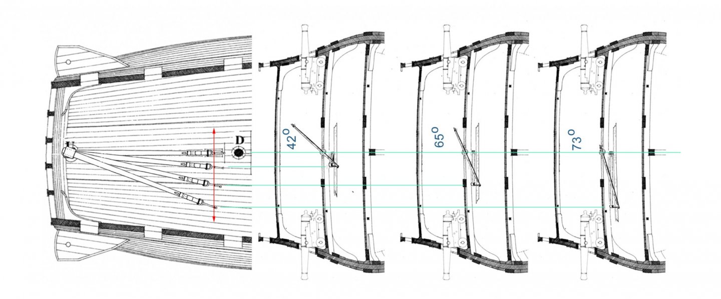
So rather than a long, dangerous, slot in the deck above, all that is needed is a little opening, like the hood pictured in the Goodwin drawing. This has the added advantage of bringing the helmsman's head up one deck for easier communications and so he can see the set of the sails as they draw. It keeps his body down near the rowle so he can manage the staff as it lengthens and shortens as it pivots and slides. No slot required.
Thoughts?
Dan
-


USS/SS Leviathan 1914 by shipmodel - FINISHED - 1/200 - troop ship/ocean liner
in - Build logs for subjects built 1901 - Present Day
Posted
Hi to all who followed this build log. I hope you enjoyed the journey, and I thank you for all the likes and comments.
I have just posted the first piece of a new log of building the Great Lakes whaleback steamer SS James B. Colgate (1892)
If you want to follow along just click on the ship's name in the 'current build' line of my signature below. Everyone is welcome.
Stay safe and well, and a Happy Thanksgiving to all.
Dan