
.jpg.d84ec4dad1d7791e855dca06210ab6f3.jpg.40b7a0ea2cc62bf0a3ec2a716005383a.jpg)
hollowneck
-
Posts
1,353 -
Joined
-
Last visited
Content Type
Profiles
Forums
Gallery
Events
Posts posted by hollowneck
-
-
9 hours ago, Blue Ensign said:
The anchors won’t be fitted on the ship but will be included in the display case.
Very nice job on the anchors, B.E. The MDF does finish acceptably if one is careful. Once you daub on some weathering powder, one will be hard-pressed to believe the "iron" is made from pressed wood scraps.I like your tapering of the pear stocks, what a good idea. I didn't catch this detail when I crafted my anchors.
Placing anchors in your display case adjacent to your excellent model is a good, logical decision. I have a large bower anchor for my 64-gun model placed on it's display base near the bow and I routinely get questions about it usually regarding how large it is. Another option: you could put an anchor in one of the off-hull boats (just kidding).
I'm still wondering how to achieve some realistic mounting details for HMS Camilla's bower anchors. There seems hardly any convenient spot to place these monsters anywhere near the catheads and/or fore channels. I haven't found much info about how this was accomplished in real life. Like much of the sail rigging I'm now doing, I'll come up with some "creative engineering" to solve my anchor placement issue.
-
12 minutes ago, James H said:
Looking forward to seeing this.
Remember to check out the notes I added about the position of the lower stern counter. Check step 149 for info.
Erdict, this advice from James H is quite important for a successful build of the Sphinx; it comes from the prototype engineer who works closely with Vanguard and writes the manuals. The stern counter is one of the most difficult areas to get properly aligned. You'll want to look into the Sphinx Build Logs of a couple members here to see the situation and how it's been handled.
- Ryland Craze and mtaylor
-
 2
2
-
4 hours ago, Blue Ensign said:
I'm sure you will enjoy this build Erdict, it is a fine model to make.
As for emulating the builds of others, we all do it, picking up ideas, and learning from methods employed, it's a lot of what MSW is all about.
Have fun.
B.E.
As Blue Ensign said, this model kit is a fine one to build, very rewarding. This forum is an amazing resource for all model ship builders, novice and expert alike. In all likelihood if you can’t get a satisfactory answer here to any question, an answer likely doesn’t exist!
Since this is not your first, you already know that a fun build isn’t a speed competition. Your time frame of 18-24 months is about right for steady work to a completely rigged Sphinx. Any tough spots you encounter, the answers will be here across several build logs for this superb kit.
I’ll be looking in to your build as I complete mine over the next couple months. Welcome aboard, weigh anchor and set your heading…for success.
- mtaylor, Ryland Craze, Mr Whippy and 1 other
-
4
-
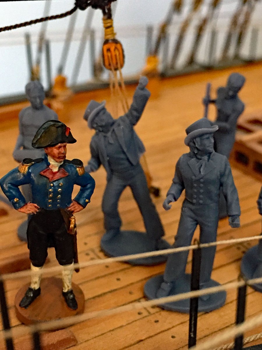
As promised, here's Camilla's recently arrived crew: two proper tars and six cannoneers (including a powder "monkey").
I will paint them over the next week or so when I'm needing another break from the final sail rigging details. These 1:64-scale 3D printed figures are impressive. The height of the figures is approximately 1” or 28 mm. Once painted, the detail on all the figures will make them come alive.
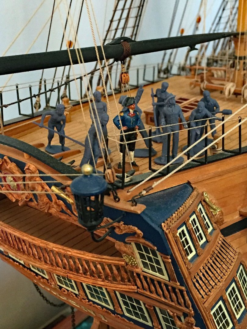
I couldn't resist arraying them on the poop deck of my HMS Ardent (64). It's also 1:64 in scale and I wish I had these when I was finishing-up this build from 2014. I am tempted to possibly grab another set of sailors from Chris expressly for this model.
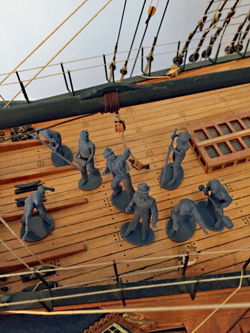

A close-up view of Cpt Pennypincher and two Royal Navy "Tars." The bases will be removed; I'll use either a Dremel or even a disc sander to remove them so they all will stand on their feet properly.
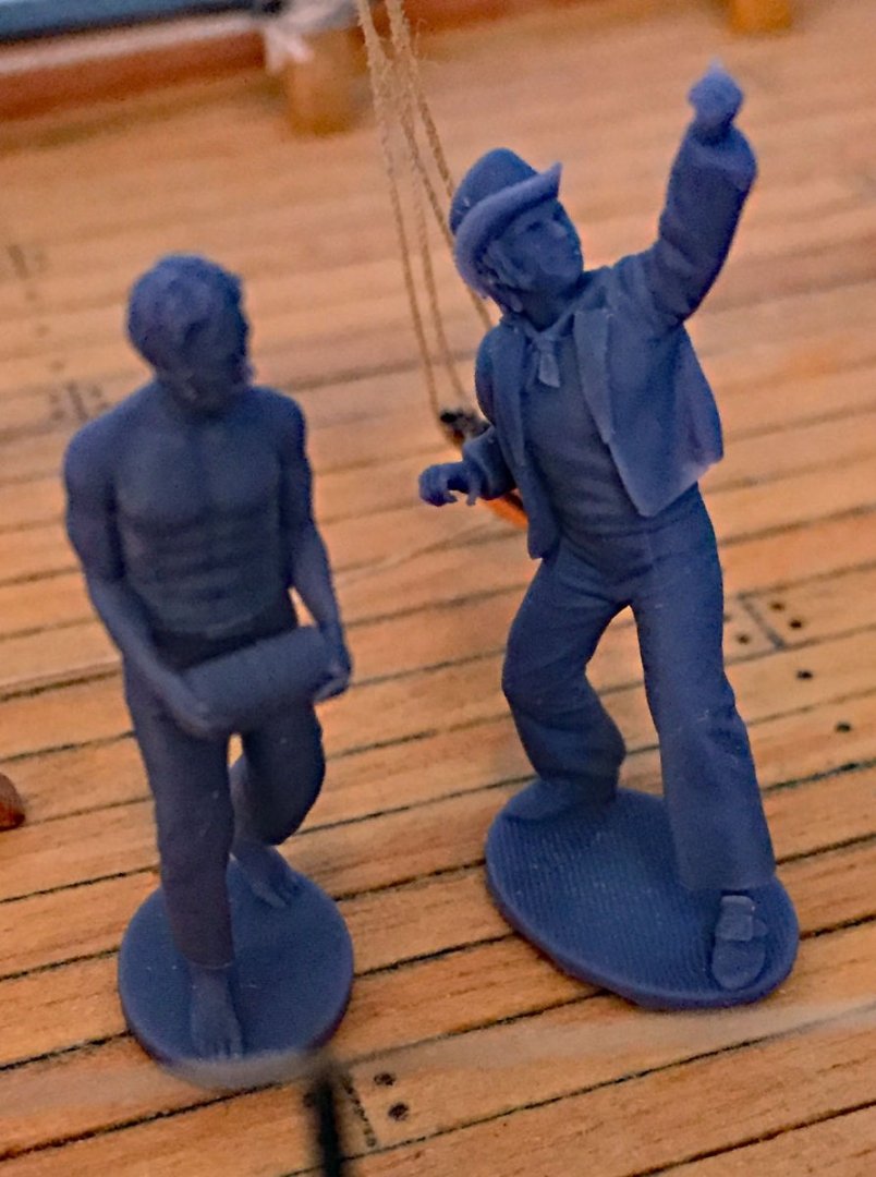
This photo’s color is reasonably accurate for the unpainted resin. The shirtless and shoeless "powder monkey." The dashing sailor with hat, jacket and kerchief. I need to do a little research on late 18th-C sailor garb before cracking open the paint jars.

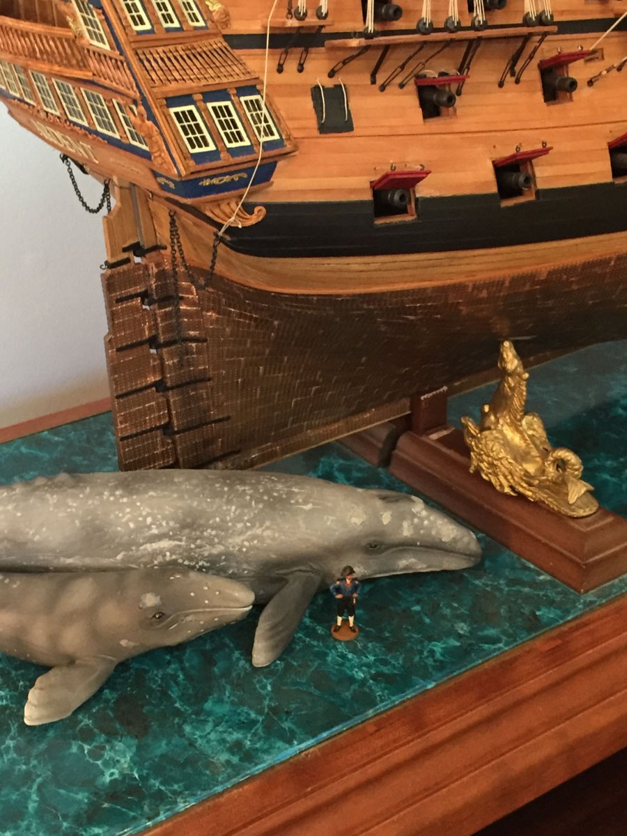
Captain Pennypincher stands along side a female Grey Whale and her calf. After completing the above model I wanted to give some indication of scale and there simply were no good, accurately-sized figures available at that time. I searched for the next closest thing which - as it turned-out- wasn’t perfect yet helped to convey the enormity of the vessel: the whales are reasonably scale accurate to the ship. The Pegasus serpent pedestals? Not so much...
I haven't decided WHERE I'm going to place my minimalist crew on Camilla. Perhaps on her stern q'deck, like I've shown here. The cannon crew is for a long cannon, not a carronade, so this position may not work for the six figures. We'll see...
-
On 9/23/2022 at 7:14 AM, Blue Ensign said:
Post One hundred and sixty-three.
Final touches.
With the boats put aside it’s back to looking at what is left to do on Sphinx.
I turn my attention to the Hammock Cranes, sorting and prepping the individual parts.
I find myself puzzled by the Quarterdeck cranes.
There is scant mention of these, a brief comment on p102 of the manual, referring to fitting them later, but nothing follows.
.jpeg.2afab72de1297a03fd918c53380ccb84.jpeg)
Prototype build.
I note that James dodged the bullet in the prototype build, they are missing from the final completion photos.
The cranes are identified on Plan sheet 11, Suppl. drawings 7. (PE93 – 103 R&L)
The cranes are handed, and specific to each location. This presents issues when the items are to be chemically blackened because each set ideally has to be kept separate, and there are eleven sets.
They can’t therefore be batch blackened, and the cleaning and blackening will have to be done on a set basis to avoid mixing them up.
.thumb.JPG.aecf67299e388f81cd61155a998a2e53.JPG)
8510(2)
Each crane consists of two parts, the crane, and a tiny base plate into which it fits. presumably up to the nub on the shaft
How it fits is not immediately clear and it looks like the base plate needs drilling out to allow passage of the crane thro’ to the hull.
The secondary question is whether it is better to glue the plate to the hull first, then drill and fit the crane, or attach plate and crane first, and then fit to the hull.
CA is probably required to glue these fitting, which raises the concern of how to fit these without marring the blackened surfaces.
I rather feel that a brief explanation of this fitting and a couple of supplementary photos would have helped in this area.
B.E.
24/09/2022
I omitted the miniscule base flanges entirely; not necessary. These also didn't allow a clean fit from the crane's end. I used a tiny drop of CA on the end and pre-drilled the bulwark holes that weren't large enough to accommodate them easily. These kind of felt like an afterthought, however I added them - and their ropes - afterall. They mount very tightly and right up against the shrouds. I painted mine flat black and added a little metallic weathering powder to turn them into iron. Make sure to file off the brass P/E "sprue" nubs.
- Dave_E, mtaylor and Blue Ensign
-
3
-
1 hour ago, Nipper said:
I've been following Camilla's progress very closely . . . she looks fantastic and now I'm thinking that I may be fitting sails to my Sphinx after all. What a superb model you're making and I can't wait to see how the Vanguard crew shapes up!
Nipper
Thank you, Nipper, your comments much appreciated. Should you choose to have your Sphinx harness the wind, I hope you’ll be able to glean some details from my photos and techniques that might make the task rewarding- and fun. Notice I didn’t include the word “challenging,” as I suspect you already are aware of this…
- Nipper, mtaylor, chris watton and 1 other
-
4
-
1 hour ago, druxey said:
Sorry to read that the lurgy (pronounced with a hard 'g') laid you low despite the vaccines, Ron. Hopefully all will continue well for you now. The model is really taking on life: I can't wait to see her heeled slightly in her sea!
Thanks, druxey. Having had all the “protections” I have no idea how the sneaky virus made it through my layers of antigens! I am feeling so much better now and besides, the virus has no idea how many more models I am determined to build!
- druxey, chris watton and mtaylor
-
3
-
2 hours ago, Blue Ensign said:
Great job on the sails Ron, she is looking wonderful.
Glad you've recovered from the ‘plague’
B.E.
Thanks, B.E., as anyone who has also experienced this indicates, it’s no fun. Symptoms can run the gamut of unpleasantness.
Your Sphinx is looking beautiful and I wholly agree that your superb little boats will look perfect, “de-cluttered” from the ship’s skids. Congratulations.- chris watton and mtaylor
-
2
-
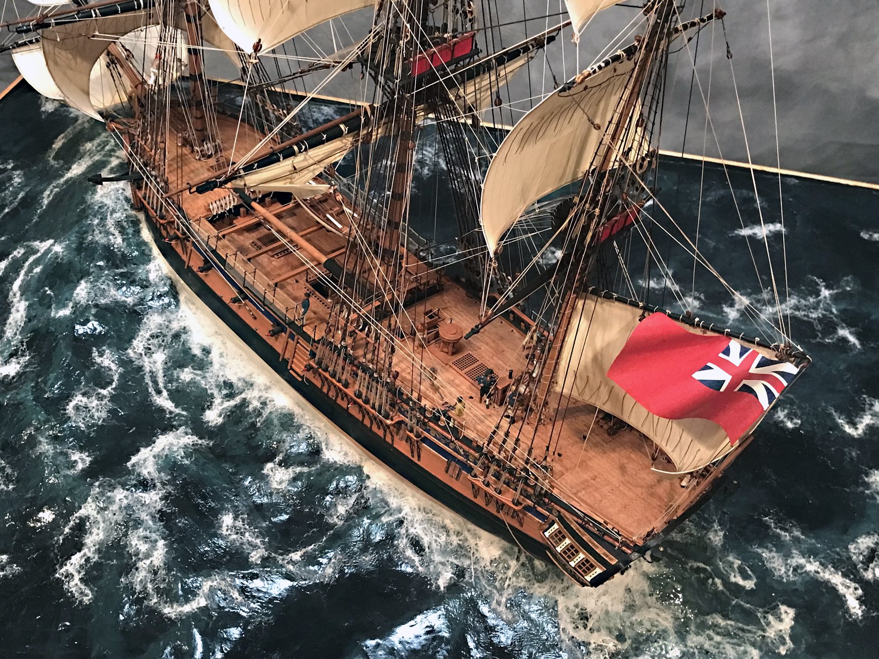
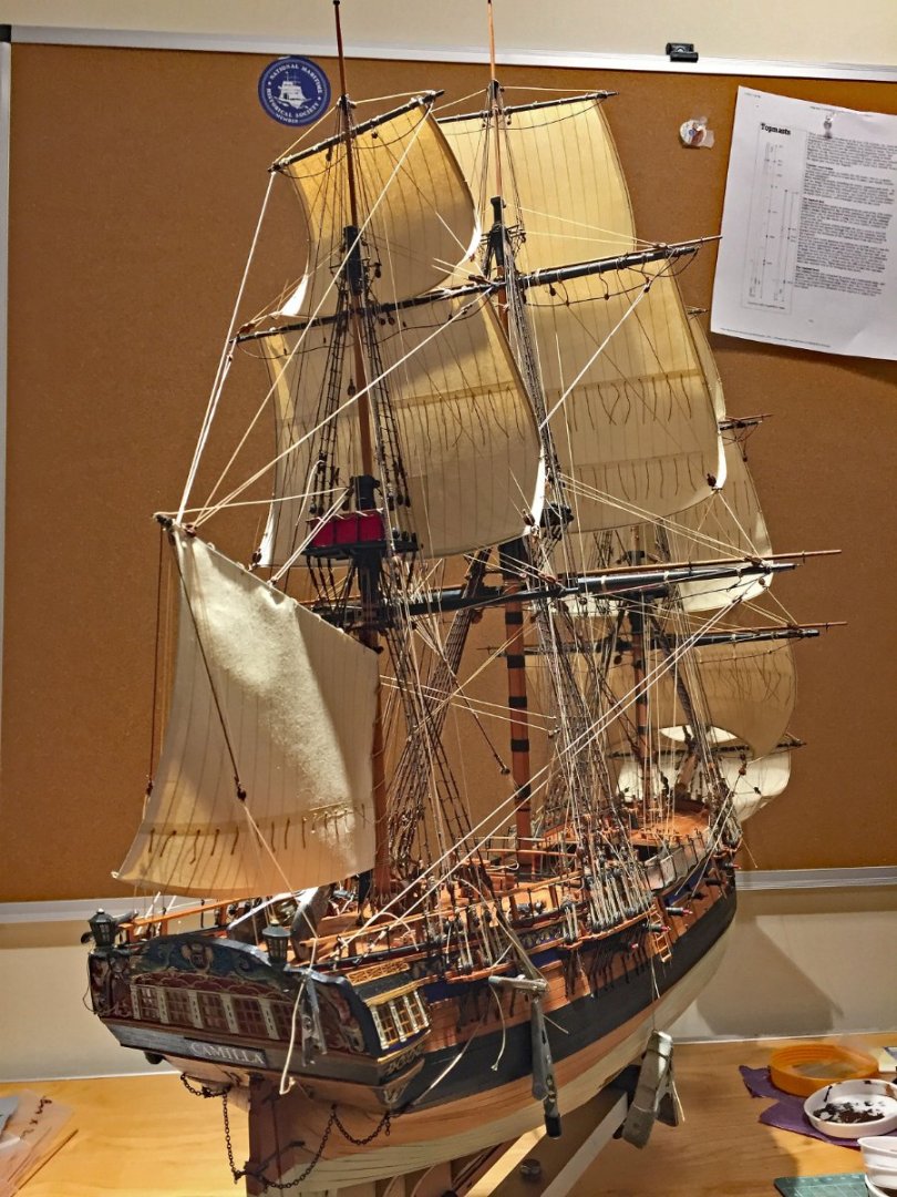
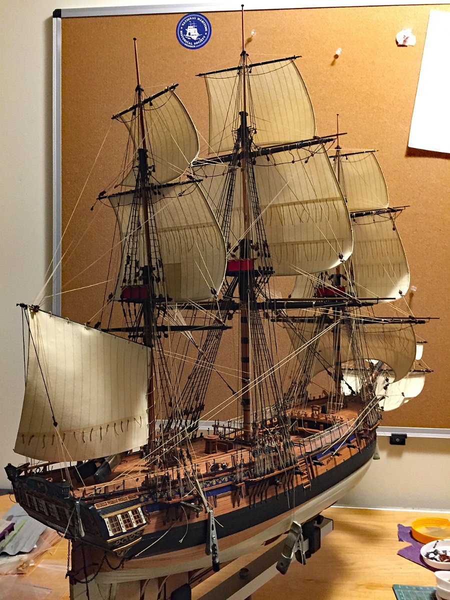
After a nearly three week hiatus - and having dealt with The Plague (Covid's latest variant) - I was back in the shop this past week. And finally felt like a human.
It's good to be back - even with attenuated shop time - working on the final stages of my HMS Camilla (now King Charles' Consort!).
God Save The King.
Obviously, I'm also pleased to be sitting in front of my computer once again, posting photos and some text on this Build Log.
It's also good to still be around after a mean bout...I've had all my multiple inoculations, but it still laid me low for a while.
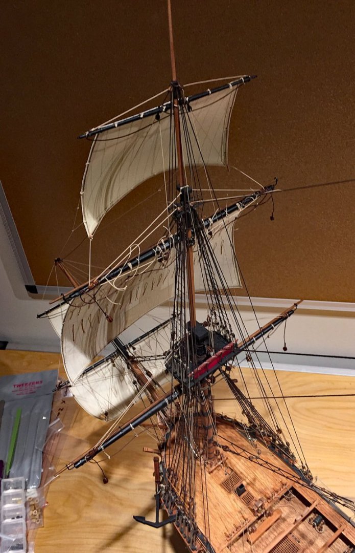
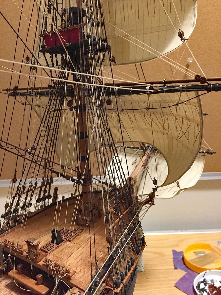
Here's a photo update of last week's progress on sail rigging.
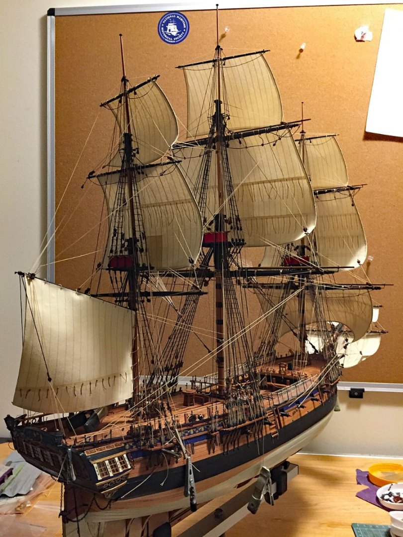
The Big Picture: nearly all sail rigging lines have been completed: clues, sheets, bunt and bowlines. The Mizzen topgallant is skewed and needs tweaking. Once the sail rigging is finished, the rigging clips that temporarily secure the lines get removed as the tension from starboard-to-port or bow-to-stern gets properly balanced. Once this is completed, then I'll make numerous rope coils for the belaying and cleat positions. The coils will be carefully positioned and then glued with Liquitex matte adhesive.
All the sails have been "shaped" to show them as working sails; I also refer to these now as "set" sails. The sails will be have some dry-brush painted "weathering" effects added once their final positions are secured. More on this to follow.
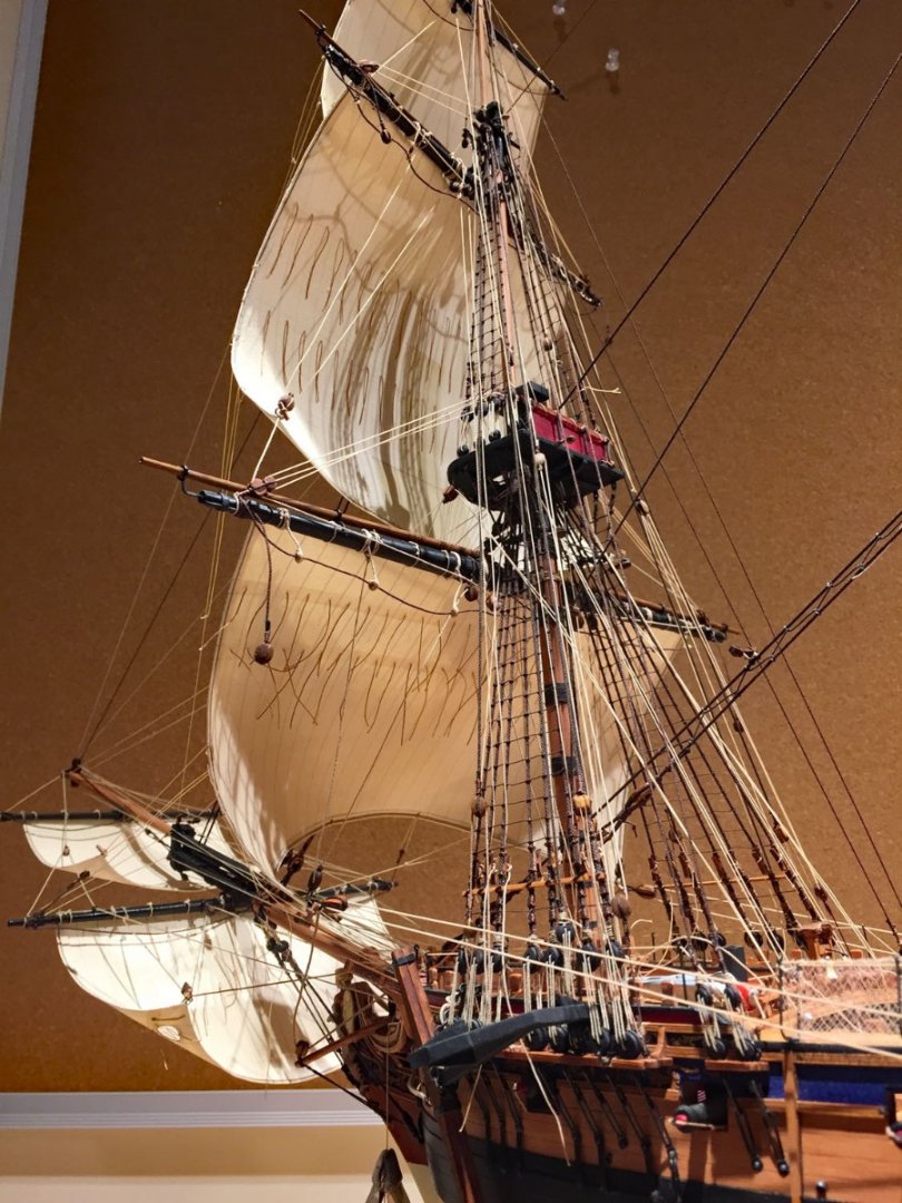
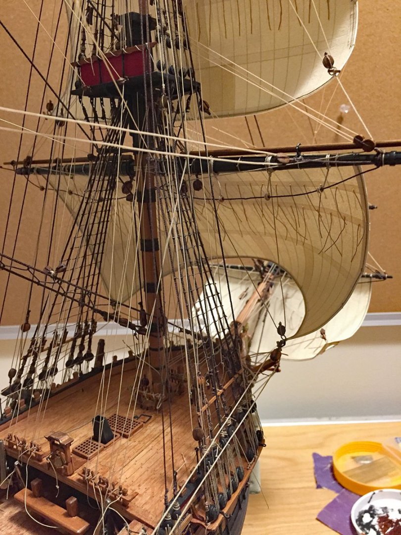
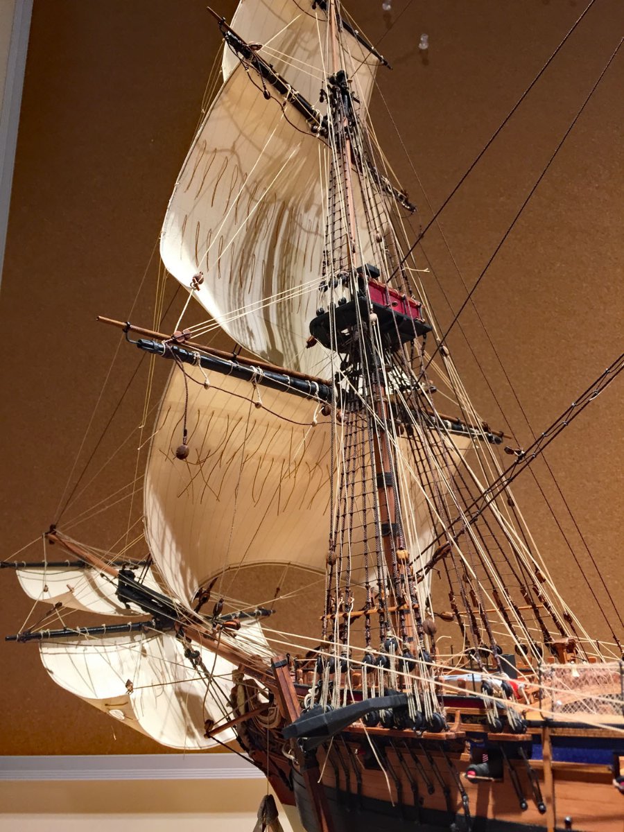
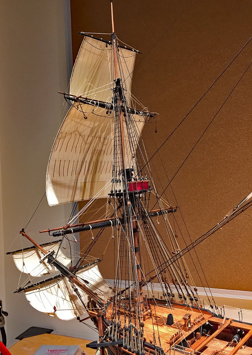
A view of the foremast with all her sails. The bowmast (bowsprit) has two spritsails, a first for me. This sail rigging was a little tricky as I've found scant information on where the sail management lines belay. It's a very tight fit in the foc'sle for all the necessary lines. I had to add additional blocks and cleats to accommodate some of these lines.

Another view of the sails on the foremast from midships.
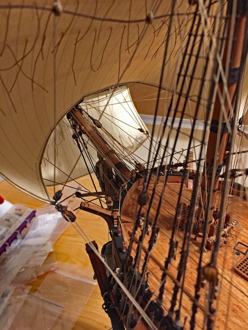
It's a tight fit at the foc'sle's stem! Running and sail rig lines at the jeers have yet to be secured. I do attach these with CA glue after they're properly tensioned and trimmed-off. Once appropriate rope coils/hanks are positioned, they hide the CA glue terminated falls.
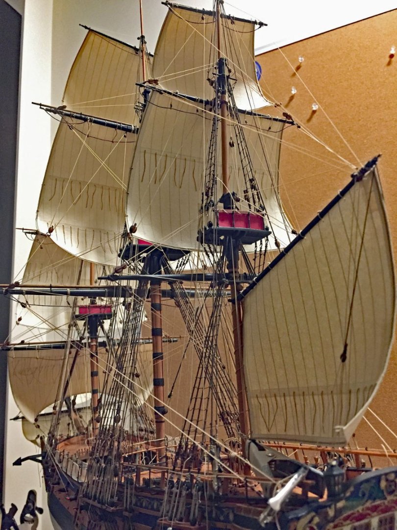
I haven't determined the placement for block & tackle on the spanker (gaff-mounted) mizzen sail. I'm researching how and where to secure this particular sail, hence the large clamp holding it in temporary position.
Keen eyes will see that the main course carries no working sail; I'm fashioning a furled sail from silkspan only for this yard. The sail will be "foreshortened" and hauled to the yard with her buntlines and clues, and lashed to the yard. Unlike all her other sails, This sail will not have a core of bond paper as it isn't necessary and would be extremely difficult to fashion properly with the stiffness of the paper between silkspan layers. This will be the final sail to be mounted because I needed unhampered access to the mid-deck belaying points at the jeers and cleats.
Those who have been closely following my log will note that I’ve changed my mind on how to treat the large main course sail: I’ve wavered between: A. Omitting it entirely, concerned somewhat with what it visually hides of deck detail, B. Mounting a full working, billowing sail, or - C. A furled sail that hides only small details of it’s yard but completes the ship’s main, full complement of sails (minus staysails). As I’ve previously mentioned, I originally planned to add stunsails - the ones extended from the ends of the main courses and top yards - but these would have made the size of the overall model especially unmanageable in a diorama.
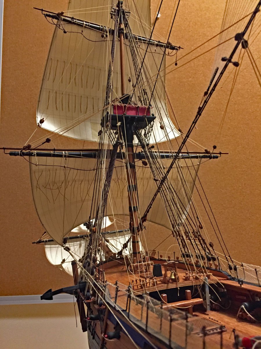
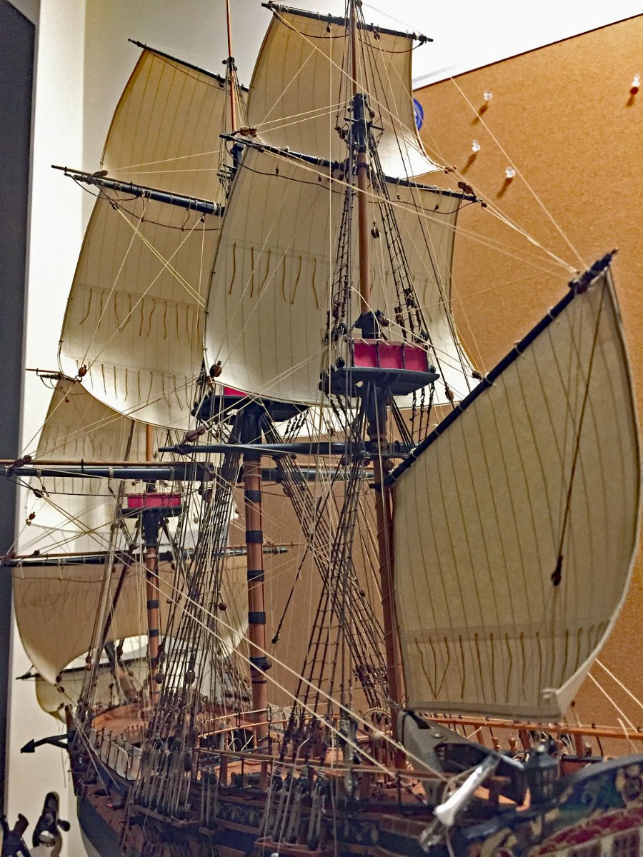
The starboard view of the fore deck. Those fore course and foretop sails are responding to a strong wind blowing across her open midships. Anyone who has sailed in a stiff wind knows that sails can take on dramatic shapes when they're closely hauled against the prevailing wind.
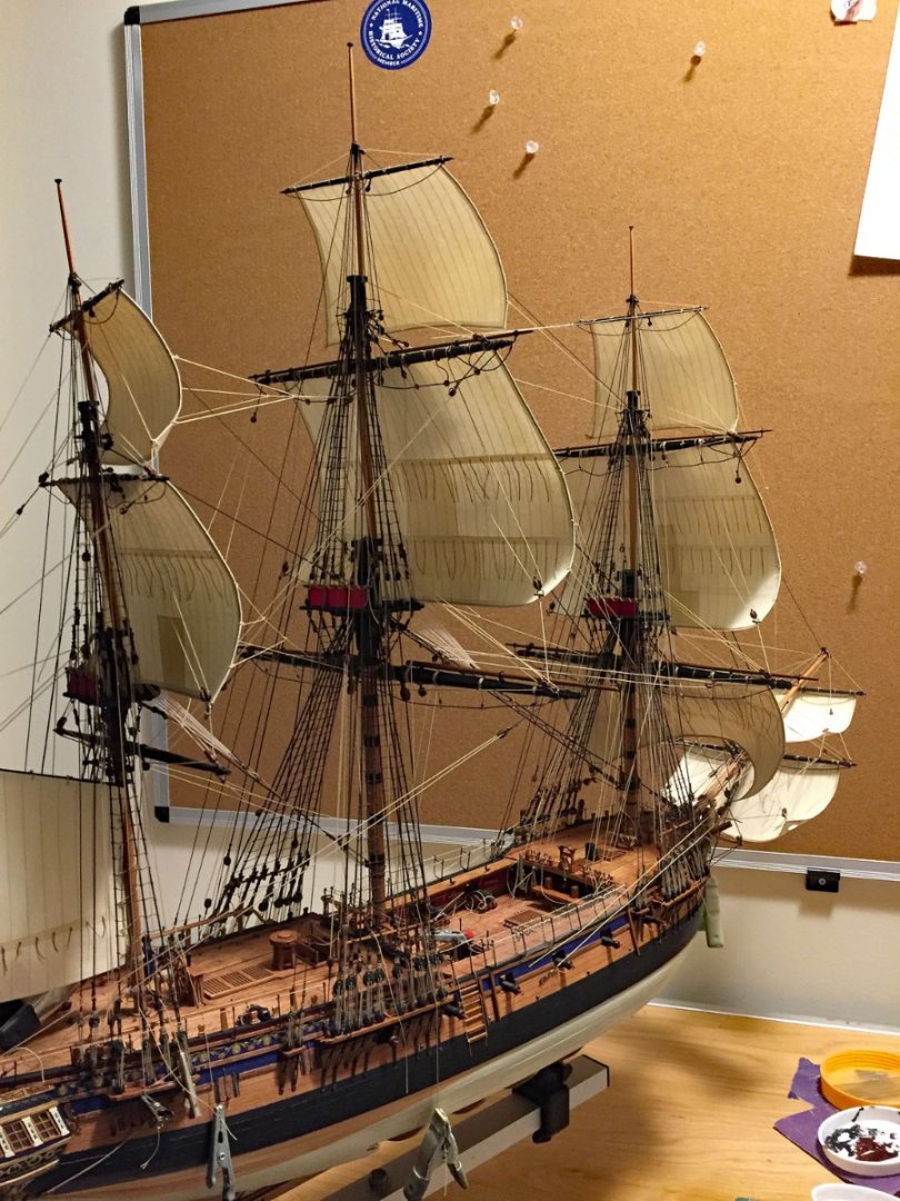
Another starboard view; a few braces and a couple clue lines for the topgallants and foretop are still on my check list.
I will note for others who may desire to add sails to this excellent kit that there is no sail plan included. Reference materials are available however, even these don’t deal with some of the realities of final ship configurations, especially on how and where the rigging lines were terminated. I consider this “creative problem-solving”, an exercise that some modelers won’t have the slightest interest in pursuing…
BREAKING NEWS
I just received the rest of Camilla’s “crew” who just arrived by Royal Mail (&USPS) from the U.K. In addition to Cpt. Pennypincher, there will be a full cannon team as well as a couple sailors recruited from Vanguard’s 3D printer in 1:64-scale…photos to come. Soon.
-
4 hours ago, Chuck said:
Thank you Chris for the best scale figures I have ever seen. It is so good not have a mini that looks like a cartoon. These are so realistic.
I'm excited to see Larry's work on Chris' new Royal Navy figures. I've ordered a couple of the sailors and a cannon crew from Vanguard and plan to add them to my latest model/diorama.
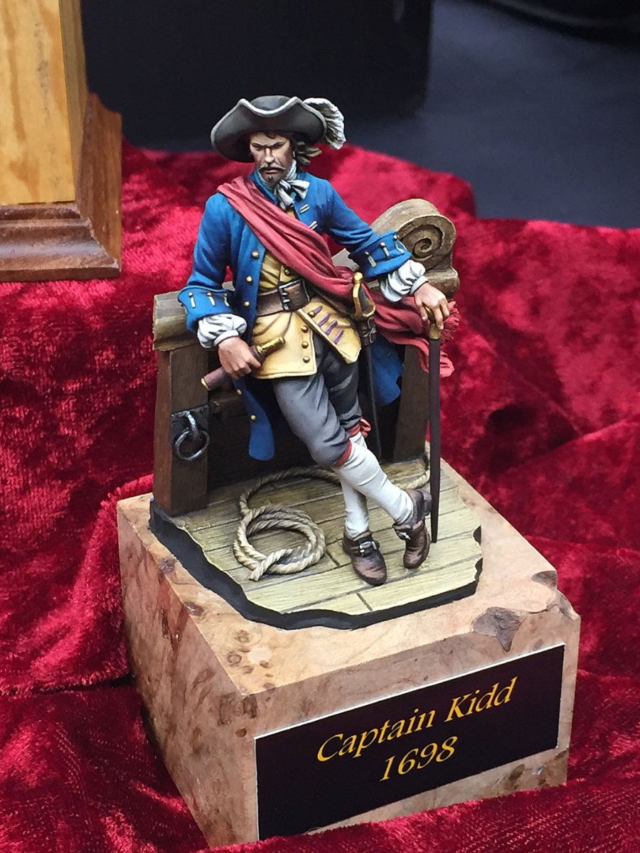
This April, I went to a local Exhibit/Conference in PA that's sponsored by the MFCA (Miniature Figure Collectors of America - link: https://www.mfcaclub.com/). Who knew this existed! This is also a large collectible international hobby.
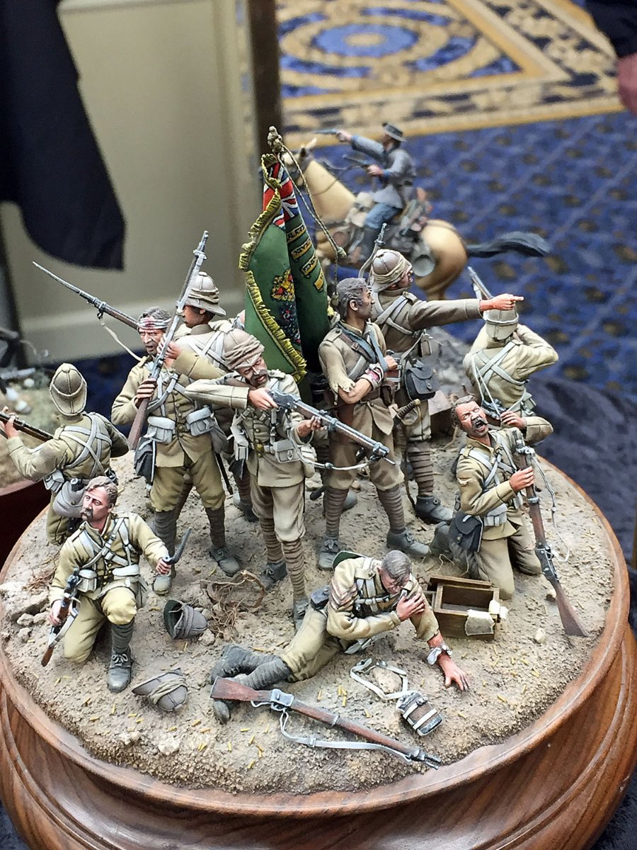
I was impressed with the extraordinary quality of the figures with a wide variety of subjects and scales: all superbly sculpted, painted and displayed. Serious collectors pay MUCHO $ for some of these. Many of the artists with whom I spoke were from Europe. One creator (from Spain) told me he works on commission only and can take up to a year to craft a single figure.
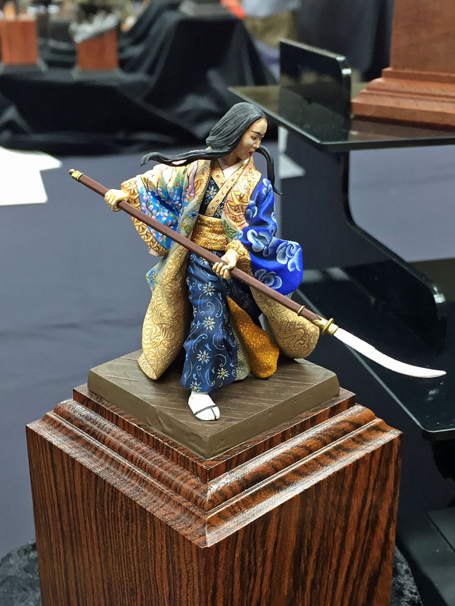
Here are a couple photos (of many!) of this artistry.


When I inquired about this Warrior Geisha, the artist told me I could have it on a "Show Special" price for $4,000. After a few conversations, I stopped asking artists how much they were asking for their creations...
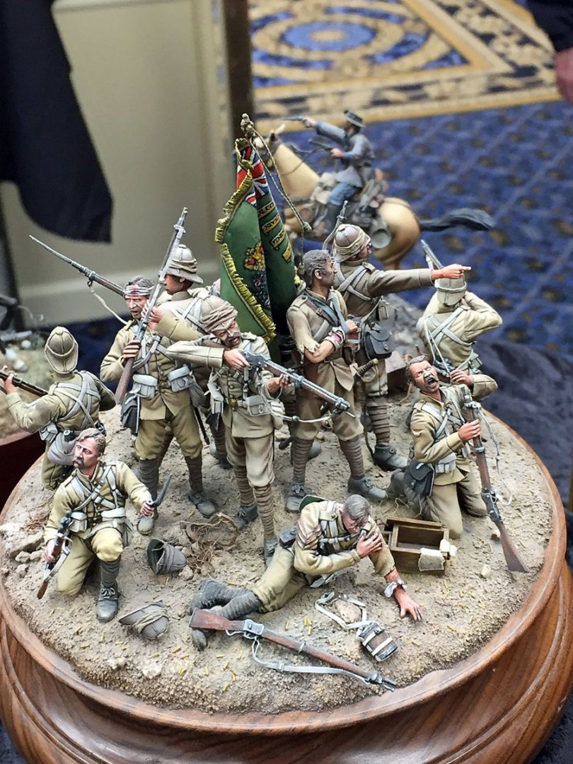
I recall the scale here was 1:35. Many plastic military modelers work in this "standard scale."
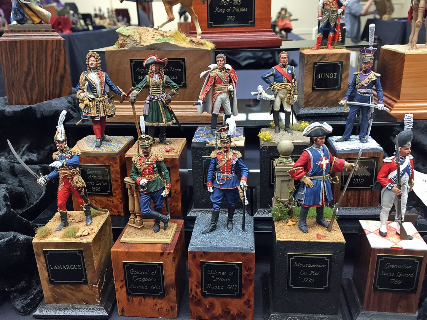
The presentation stands are equally impressive IMHO. Exotic, burled and polished hardwoods mostly.
In addition to creating custom "sculpts" for collector clients, some artists license their figures for resellers who make the unpainted figures available for mere modeling mortals...
-
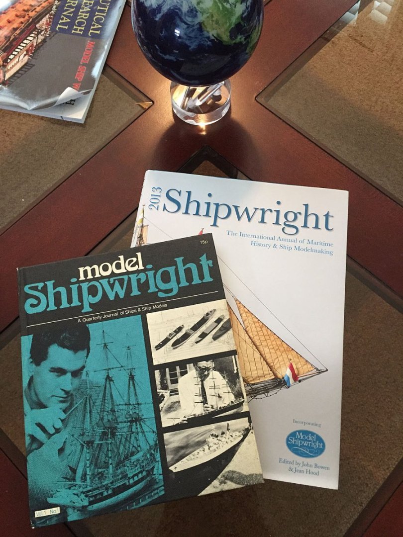
On 9/18/2022 at 1:30 PM, Blue Ensign said:
Nice collection Chris, remarkable similarity to my own library, even down to the old Model shipwright editions.
Here is an "Alpha" and "Omega" for Model Shipwright; Vol 1, #1 (1972) and the last edition in 2013.
- Ryland Craze, Canute, mtaylor and 5 others
-
8
-
2 hours ago, Rustyj said:
Well, the Dutchess of Kingston has officially been finished. It took me some time to finish working around
my other builds, but it was well worth it. I want to commend Chris Watton for producing such a wonderful
kit that looks great and is a pleasure to build. I look forward to some of Vanguards future releases and trying
to figure out what one I want to build next.
Superb job, Rusty. Congratulations.
Having personally seen your models up-close these last few years, I can attest that your work is an excellent example of high-quality craftsmanship combined with a good quality kit!
I can highly recommend Vanguard's HMS Sphinx kit. It's the "next level" for high-end kits IMHO. Lot's of innovation and excellent materials and extensive plans. Also, the next large kit from Vanguard will be the HMS Indefatigible, an (in)famous 64. It won't likely be available until next year. It's on my short list.
-
48 minutes ago, chris watton said:
Cheers!
The 'Laser room' is only a third of the space in the converted garage, but I feel I may outgrow the place in a couple of years.. I know that I will need to replace the smaller 40w laser with another larger 80w if things continue to go well.
I, for one, don't believe there is an "if" in Vanguard's future!
Like all successful, talented entrepreneurs, you'll just need to continue to pace yourself and its obvious corollary, the business.
-
Chris, thanks for taking the time to share photos of your growing business. Big machines. Bigger essential wood inventory!
Glenn is correct that in good time you’ll need to have a larger “factory.” I especially liked the photo of the row of printed figures on the shelf.
I’m excited to paint my Vanguard/HMS Camilla gun crew, place them on-deck in a few weeks when I christen her launch with my Cpt. Pennypincher.
- mtaylor, thibaultron, AJohnson and 5 others
-
8
-
I just realized the second photo in my last post (carved wood section) may be slightly obscure without better context.
I'm starting to lean into the design steps of my diorama here because these considerations are critical to how I approach making water depictions. I believe several MSWer's will be interested in this step as well as the actual water making steps and materials.
I still have lots to accomplish with my sail rigging, but for the most part this has been explained in quite some detail. My next updates will show completed "sections" with their finalized sails and their extensive rigging (Fore, Main, Mizzen, etc.).
Looking ahead...
Here are a couple photos showing a prepared base where I've placed my completed model(s) temporarily into a shallow "pan" of custom architectural millwork. You can see the custom sides of the case, the plywood bottom and attachment blocks that fasten the mill-worked sides to the base. In this instance, the depth of the case to contain the ship and its diorama was only 1 inch (after attaching the 1/2" ply base).
In contrast, the sides for HMS Camilla's diorama will be 4" high, mainly for the subsequent creation of a turbulent sea with large wave action but also to have enough "depth" to accommodate the model's hull.
These photos are from my last diorama project that features an 18th-C Japanese village being visited by a cargo ship delivering supplies.
There are photos of this completed model diorama in my gallery;
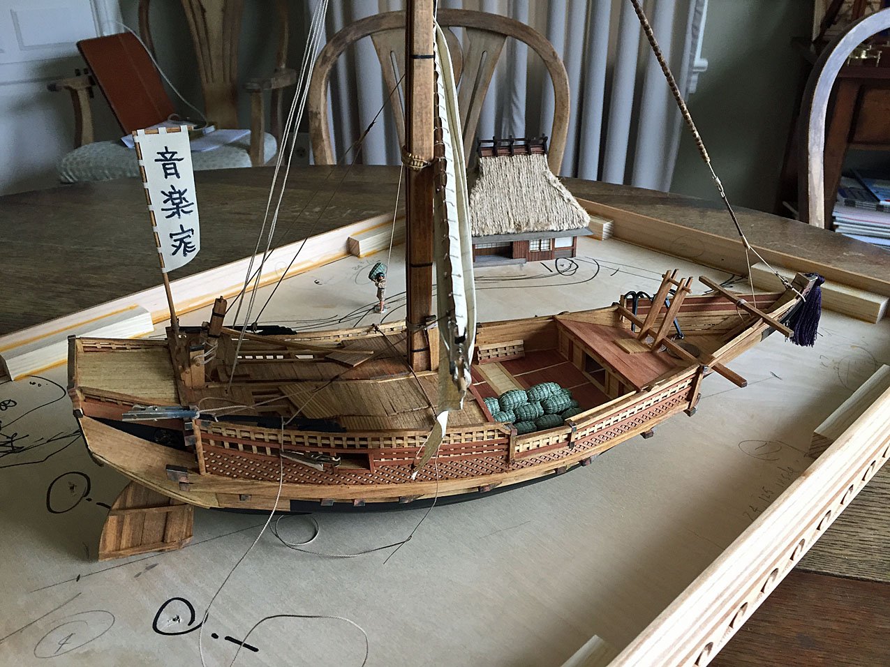
The ship model is nearly complete (there was additional rigging to be added). In the background is model of a Japanese teahouse that was included. I had an idea of what I wanted to see as a completed setting but everything didn't come together until I started depicting a shoreline and landforms. The rice bales and the figure were key to my final vision of the ship's "mission."
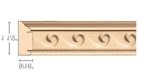
This is a graphic of the millwork section that I used for the sides of this "Takes A Village" diorama. I'll acquire the 4" high casing millwork from the same vendor for my Camilla diorama. This graphic is chair rail molding and it will be turned upside-down for the case sides. I plan to do the same thing with the door casing millwork for Camilla's base. You can see that the height of the chair rail molding is only 1.5". The sides for Camilla's base will be 4" high; the sides will also need to allow for an inside measurement that is less the thickness of the plywood base (1/2"- maybe 3/4"), similar to my other diorama depictions.
- BobG, chris watton, Paul Le Wol and 5 others
-
7
-
 1
1
-
3 hours ago, James H said:
So, over in the cheap seats, you are now fully informed.
I was slightly startled to see the telltale "baby's first month" yellowy/beige background color on the commentary (read: "criticism") about your planking decision for Indy.
Yep, lot's of experts over there, but no expertise.
- chris watton, thibaultron, mtaylor and 2 others
-
5
-
Welcome Steve. Model makers and artists welcome here. Looking forward to seeing your progress on that impressive model!
- Dave_E, Keith Black and mtaylor
-
3
-
Continuing Inspiration for sailmaking...a book of wonderful paintings... as well as my choice for building the casework for Camilla's diorama.
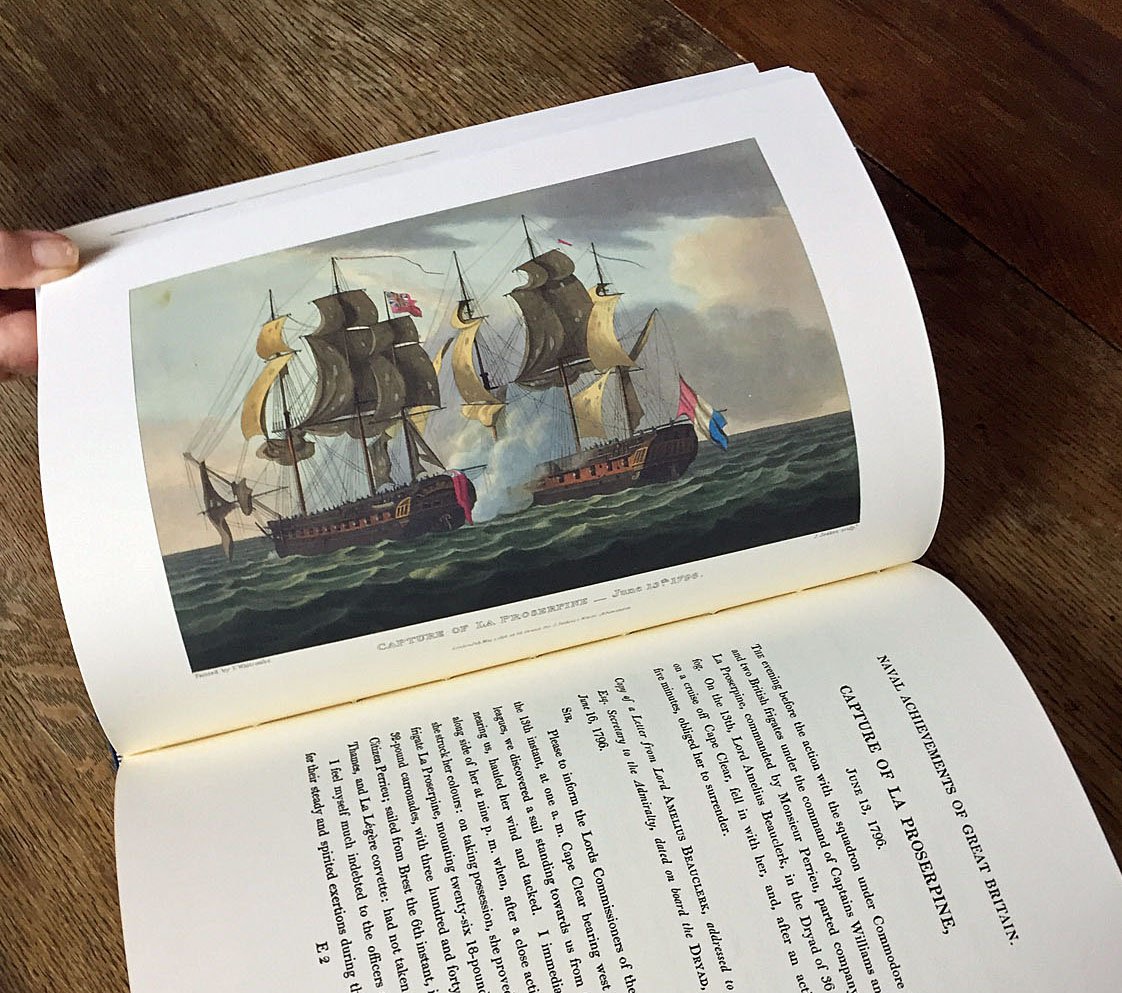
Within the last few weeks, I was fortunate to acquire a beautifully printed volume of 18th-century, aquatinted engraving reproductions in Naval Achievements of Great Britain by James Jenkins, a limited edition publication and 1817 homage to the British Royal Navy. This particular volume is also a limited edition reprinted one from 1998 by London publisher, Sim Comfort & Assoc.; the original edition as well as this latter one features fifty-one color plates along with extensive explanatory text that covers the subject of each color engraving. The beautifully-bound, large volume ("Octavo"size, about 14" h X 12" w) features the detailed artwork of one artist (Thomas Whitcombe) who was commissioned by publisher Jenkins to memorialize famous sea actions of the Royal Navy between 1793 and 1815. Uniquely, Whitcombe had been an officer in the British navy and his knowledge of warships was first-hand and intimate.
Every page reveals important and interesting details of the sailing warships in this era in both artwork as well as textual references and data. When I study these photos, I immediately think that these paintings are the "Instagram Photos" of the early 19th-century. Black & white photography wasn't invented for a good 30-40 years after the original volume was published.
The 1998 second edition book explains that the color pages of many of the original publication from 1817 were literally torn out and framed as wall paintings by those who couldn't afford to purchase original artworks by esteemed painters of the era. Although arguably the re-printed engravings in this volume may be perhaps even nicer than the original printing of 1817, I have no plans to rip-out any of these to hang in my shop.
I have been perusing the depictions throughout (all 51) as I lean into the final stretches of my build of HMS Camilla and her impending diorama. Admittedly, I'm still taking breaks from the tedious sail rigging.
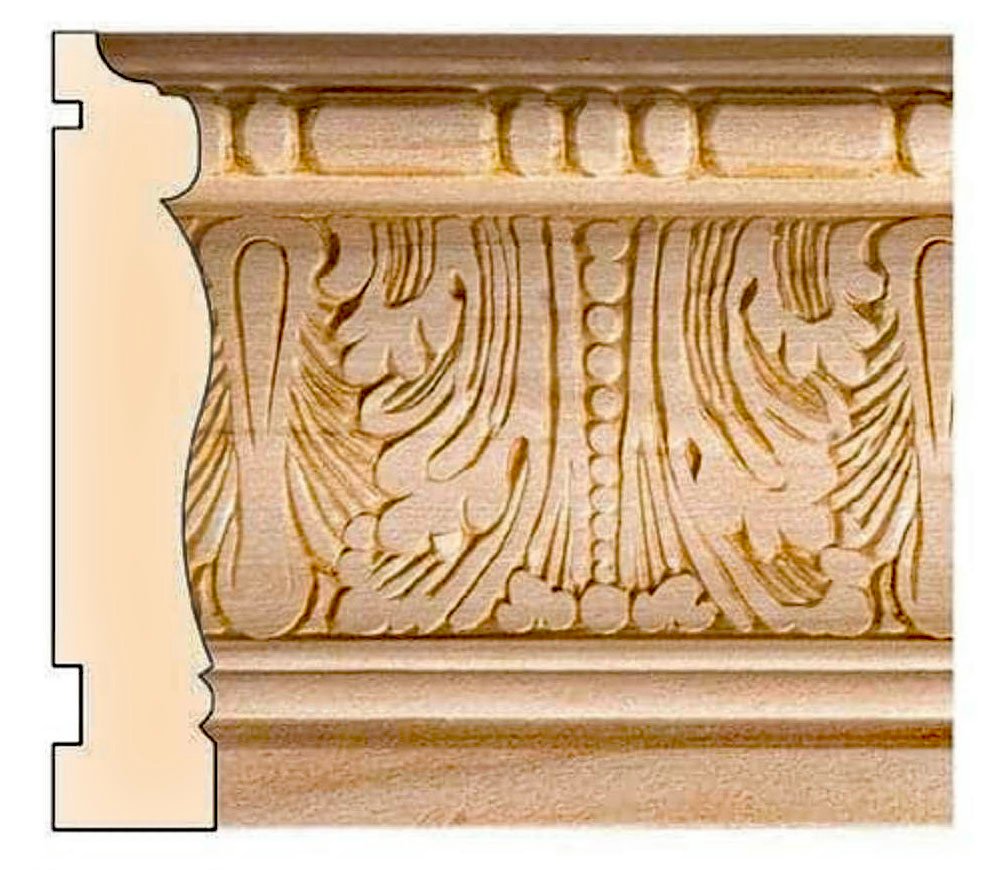
HMS Camilla's diorama requires a "pan" of sorts to not only feature the completed model but contain the "water" setting as well. I have sourced a very specific architectural wooden millwork made from poplar. This millwork is normally used by interior finish carpenter artisans for door casings who go to similar vendors I'm purchasing this stock from.
Per my previous diorama depictions, I plan to make a simple, mitred-corner "box" with this millwork. The "height" of this casing is 4" with a thickness of approximately 3/4". The 4" depth will be wholly adequate to support the model's keel as well as allow for a varying water diorama depth; the casing's height also won't overwhelm the overall presentation. A straightforwardly-constructed 1/2" plywood base will hold the millwork decorative sides in place.
I haven't decided on the final colors for the casework but I am leaning toward a natural wood finish and then adding highlighting to the relief details with either a darker hue of stain or even possibly something more dramatic like a blue color stain (over the natural wood stain color - as yet undetermined). An accented coloration to the wood will flow into the details of the casework "carving." The carved details are, in fact, pressed into the soft poplar at the mill to form a continuous pattern. I plan to order a length of 94" for my case (the longest available length) and because this is a custom order I've got to order soon as it will take a few weeks to receive it.
I anticipate that after I've gathered the "pan" materials it will take about a week to build and another few days to finish before starting on the diorama's water construction.
Back to the bench...
- mtaylor, Thukydides, Charter33 and 7 others
-
10
-
Very nice casework. Love the wood choices and additional detailing. Your case presents your model beautifully.
On posting photos, Mark's suggestion should work as he suggested: by first bringing the photos into an image editing program, saving them in the correct orientation and then uploading these image edited photos directly from your computer to the forum. Using a "smartphone" for photos is fine (assuming you're doing this). Just send them from your phone to your computer first, after editing them into your image editing software, upload to the forum.
I use my old and creaky iPhone 6 for all my shop WIP photos and I haven't had any problems uploading them to my build log here.
- mtaylor, Ryland Craze and BenD
-
3
-
3 hours ago, druxey said:
Coming along nicely, Ron. Will the spritsail have water drainage holes added?
Thank You, druxey. Here is a slightly better photo showing the waterholes in the corners of the spritsail (lower).
I'm going to add a thin painted "rim" around the holes to indicate they're grommeted (stitched) around the openings.
- BobG, Blue Ensign, Old Collingwood and 5 others
-
8
-
18 hours ago, Landlubber Mike said:
That looks fantastic Ron - amazing job! Thanks for sharing your techniques with us.
You're quite welcome Mike. I hope my details for making sails (and their required rigging) helps those who would like to add working sails to their models. I realize that for most, "working sails" on a stationary model - and not cruising in a diorama - is something that most will choose not to do.
- mtaylor and Landlubber Mike
-
2
-
-
I've been busy with sailmaking rigging details and here are some photos of this work over the past couple weeks. This work is very tedious as the spaces for the additional sail rigging lines get's very constrained. Additionally, to add sail rigging requires a number of block additions and belaying decisions. When adding sails (with attendant management lines), my "rule" is to work "top-down"- starting from the gallants, progressing to the topsails, then finally down to the main courses. The bowsprit/jibboom sails (two on this model) are outside this metthod as is - of course - the lateen spanker sail at the stern.
Here are some more sail prep details.
At times, progress seems sooooo....sllllooooowwww during these final rigging stages. But, I'm not in a hurry. Are You?
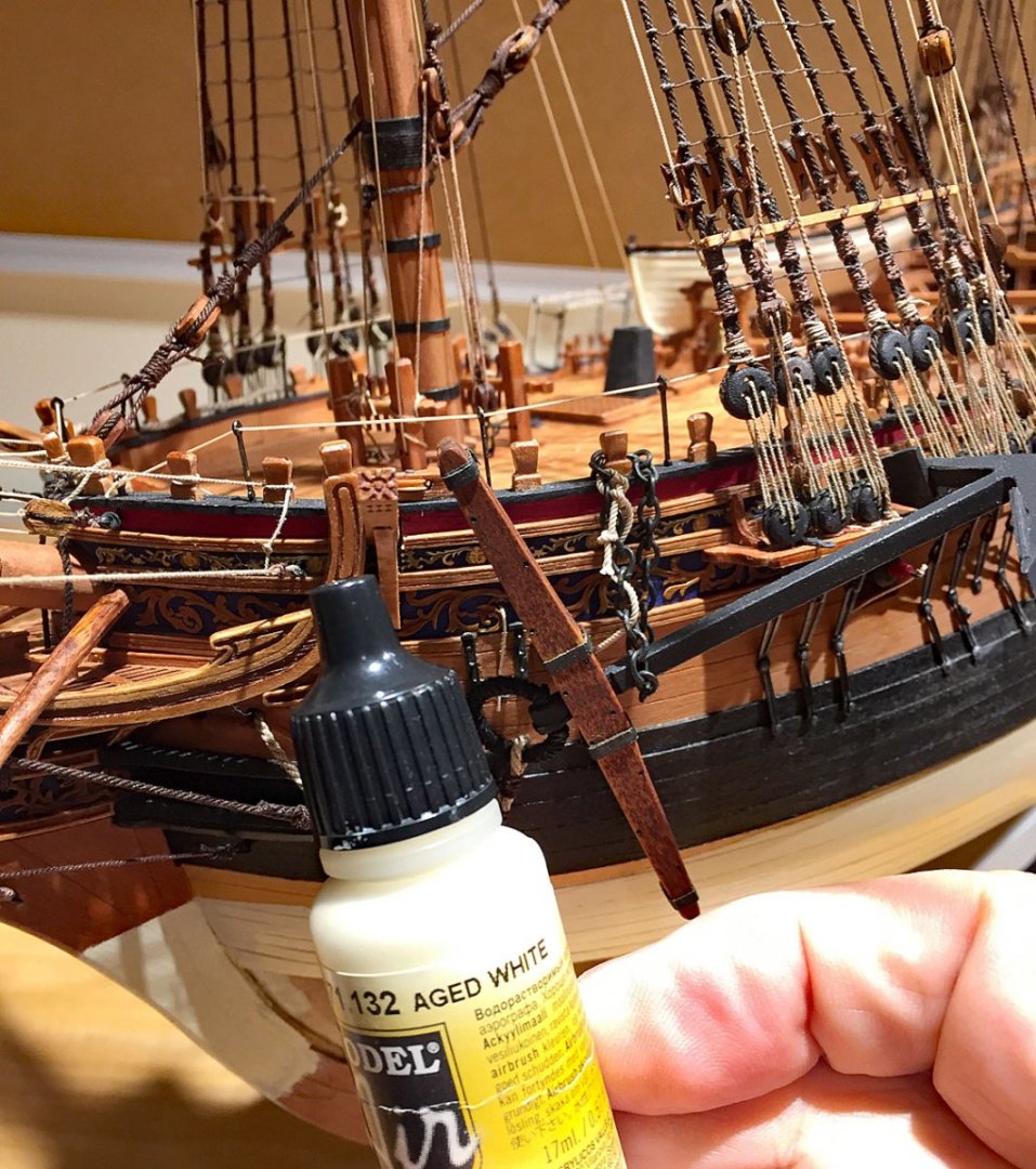
However - to break the repetitive monotony of the sail fabrication final details and their complicated rigging, I finished some unfinished business on the hull. This acrylic color is my choice - AGED WHITE. The lighting makes the paint in the bottle appear considerably whiter than it is: the actual hue does have a yellow cast to it. It's from Vallejo and this particular bottle is for airbrush work (less viscous consistency) which I also like by applying by brush (three coats). An airbrush isn't necessary for this. I masked-off the waterline with Tamiya tape, per normal, and then brushed on three thin coats. A brighter white color would be much too stark; this paint during the era would be a hue resembling "tallow."
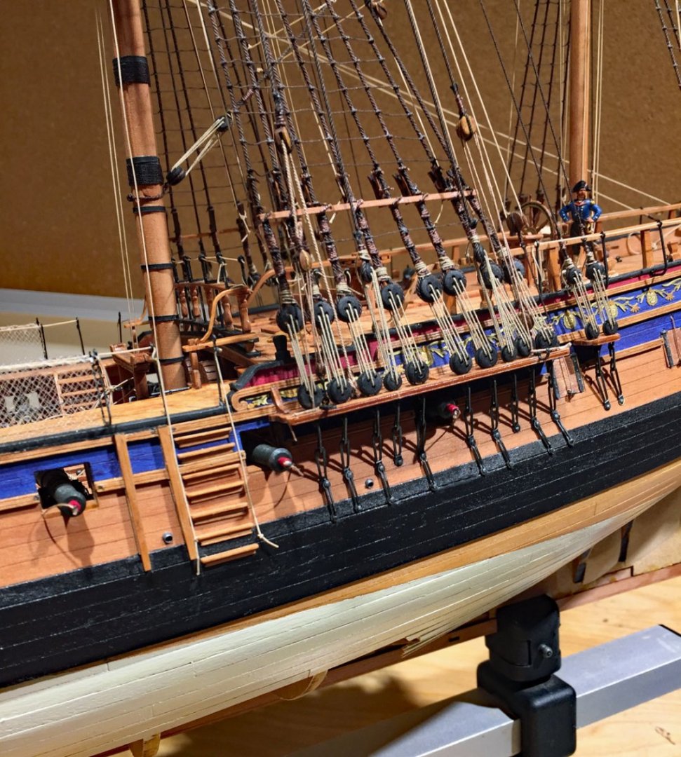
A view of the waterline painted at midships. As anyone who follows this thread knows, my model will be displayed in a waterline diorama. Hence, painting the lower hull was minimal and even this small area will be largely covered in diorama "water." I haven't decided on the angles of heeling and the exact tack of the ship but I'm pretty confident I won't be lifting the hull much above the wave action. This part of my project gets very interesting in the final stages because I'll soon need to decide on the sail bracing(s) and yard positions. I've decided to set a total of 11 working sails including both large fore and main courses - as well as both spritsails. All the sails will need to be positioned in a sensible manner depending on how rough the depicted seas are and naturally, the wind direction.
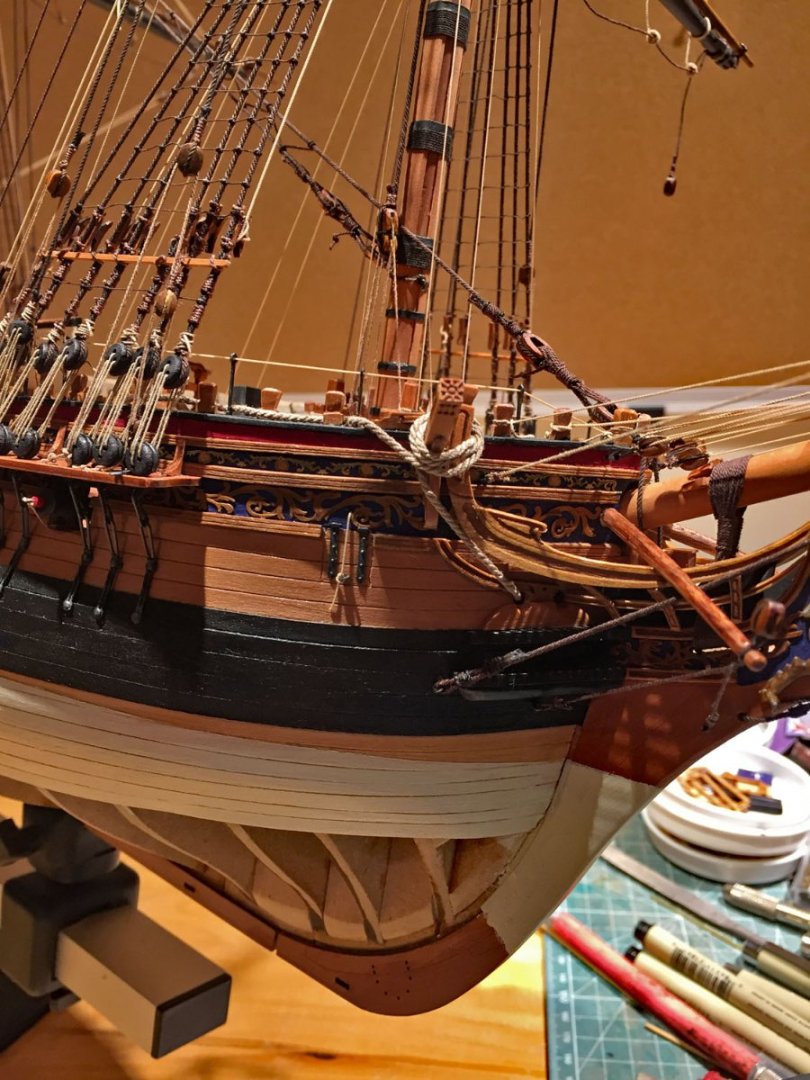
Another waterline view at the bow. This area of the model is always dramatic in a diorama: the cutwater/stem will likely be splashing large amounts of water up and around the front of the hull. When I paint the water I add some translucency to the colors so that below waterline ares of the hull can be partially seen (in some places). I accomplish this translucency (like real water) by layering colors and mixing a medium into them for the sea and waves.

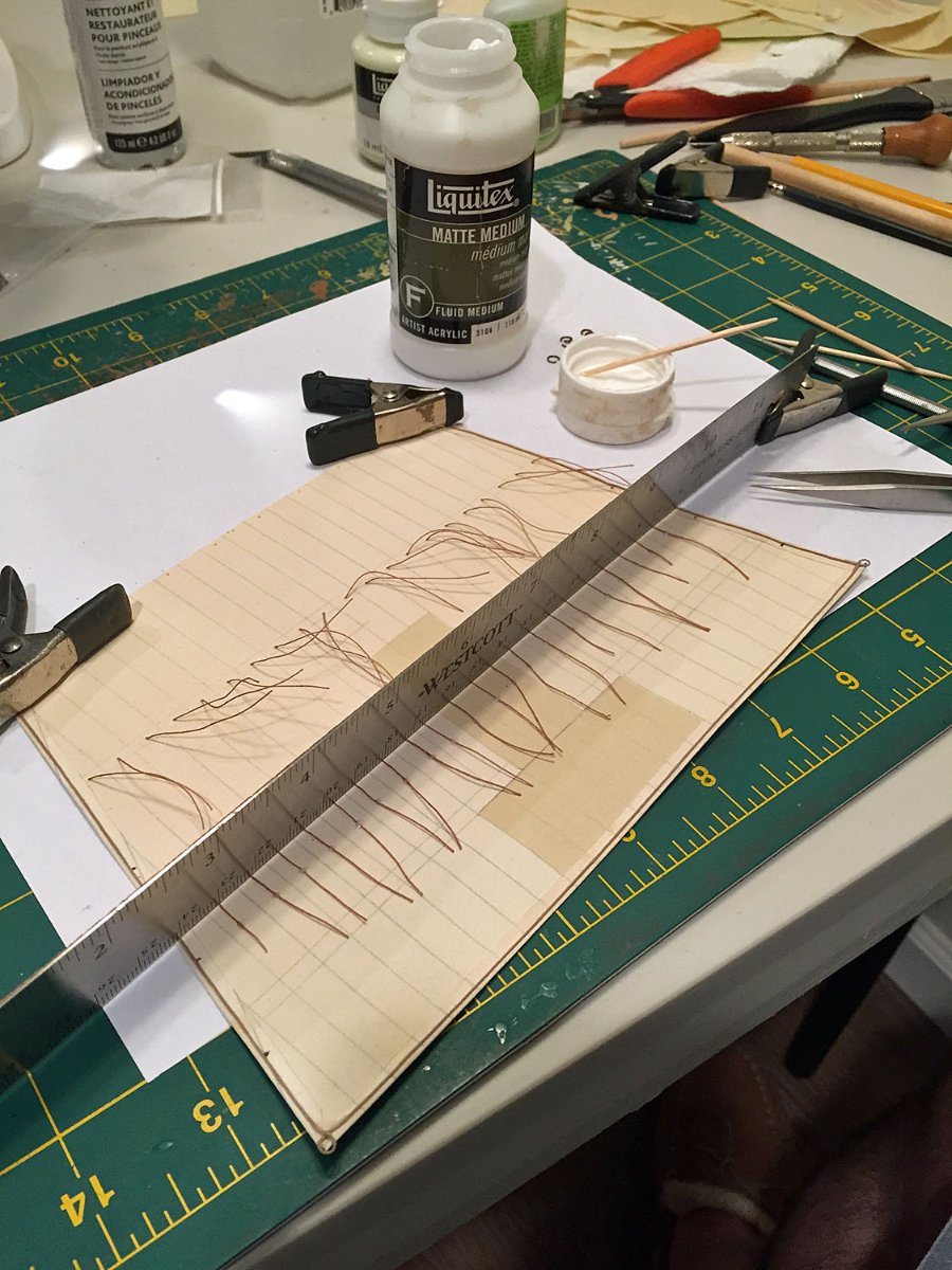
There are dozens of reef "points" to add to several of Camilla's large sails (these are the thin ropes that secure partially furled sails when the conditions call for "shortening sail"). Making and affixing lots of these reef points is more tedious than doing ratlines - in my estimation. There are about as many of these to do as there are ratlines required to tie to the shrouds. Ugh.
Once the reef point ropes are cut and inserted into the completed sail, they must be affixed in-place, at the proper lengths, fore-to-aft: I use Liquitex Matte Medium acrylic for this. The "points" on the aft side of the sail are much longer than the ropes on the non-windward (fore) side of each sail that carries these lines.
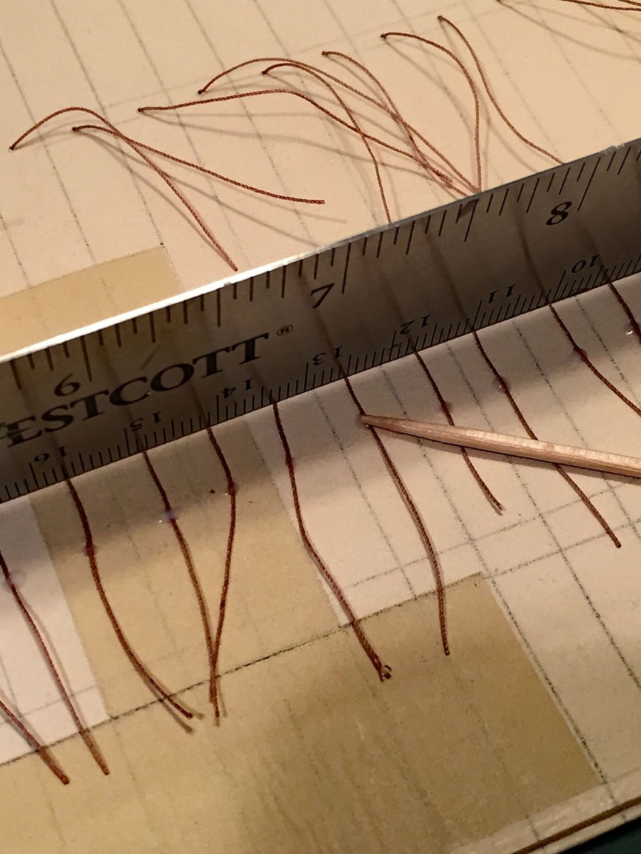
In the photo here, I've inserted individual ropes through holes in the reef lining bands (can't be seen in this view), added a tiny drop of adhesive to hold them so they don't slide out of position and wait until the matte medium dries, which is fairly quickly. The next step is tricky because the ropes want to point in every direction but the way you'd like them to hang downward - loosely; as a simple solution to hold these ropes I created a simple jig which is a ruler's edge (supported by a simple clamp on both ends of the ruler - one seen here). The edge of the ruler holds the loose ropes in rough alignment for adding yet another tiny drop of matte medium adhesive to secure the ropes a few millimeters below their pass-through holes. The ends of the ropes will be trimmed evenly after this step is completed.
As can be seen in the photo, the top band of reef points is higgledy-piggledy (that's a shipwright's technical term). The sail's linings are clearly seen here as are the bolt rope on the leeches and foot and clue cringles. Holes for the bowline and bunt line cringles will be made after the reef points are completed. This sail is the mizzen course. The holes for the sails robands have been drilled through at the head of the sail. The robands "bend" (mount) the sail to the yard.

A toothpick suffices for daubing the tiniest amount of matte adhesive to the aft reef points. This secures them firmly. I chose a gluing spot a few millimeters down from their through-holes. On working sails, these lines will be moving with the wind and at any given sailing moment will not be uniform across the sail, and shouldn't be. The lengths of the ropes will be trimmed, but they'll be loosely arrayed as they would appear in real sailing conditions. On the fore sides of sails with reef points, the matte adhesive is used to affix much shorter lengths of the reef ropes. These points are more uniformly arrayed across the fore side of their sails with considerably less randomness.

It's getting very busy in Sail City.
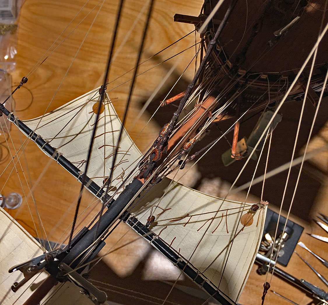
Here, Camilla's two spritsails have a majority of their sail running rigging affixed. Keen eyes will see that the Spritsail topsail - at the tip of the jibboom - still needs it clues to be rigged...which leads to the next photo.
As mentioned earlier, adding sails requires a host of additional blocks and decisions about where to belay the falls that result.
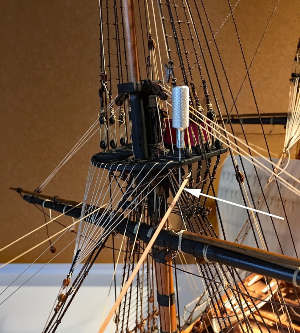
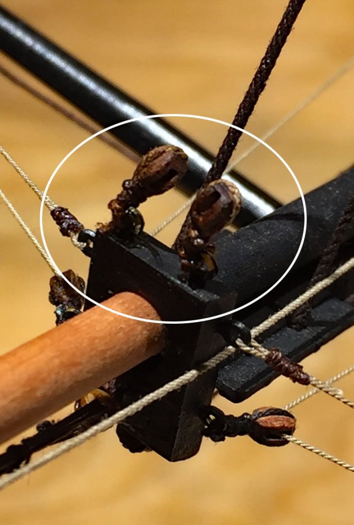
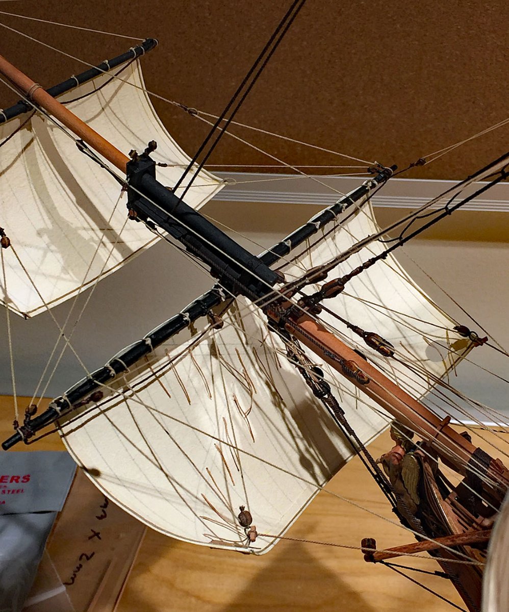
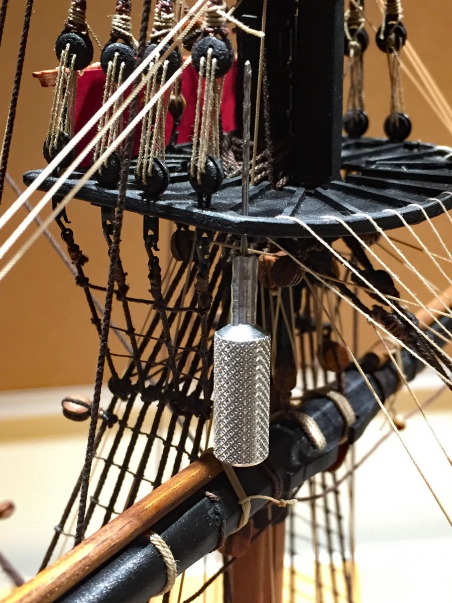
In the case of the Spritsail topsail, blocks need to be added to the foretop. I should have remembered to do this at a much earlier stage of my build, but - I didn't. Thank goodness for my trusty #72 thumbdrill. After two holes are carefully drilled into both sides of the top, an eyelet (bolt) will be glued in (facing downward). There are sufficient number of P/E brass eyelets left over in the kit's rigging provisions; the "eyebolts" are painted black. The eyelet will hold a single-sheave, stropped block UNDER the foretop and receive the clueline from the Spritsail topsail.
The arrow points to a guide that I used to determine an unimpeded run from the topsail's clue (sail corner) up to the foretop. The guide helped me to determine the exact position of the hanging block for the sail's line. It's a perfectly straight, 1.0 mm square piece of spare pear stock and I've inserted it to an approximate location of where a block will be later positioned.

Both undersides of the foretop need a single-sheave block for the spritsail topsail's clue lines.
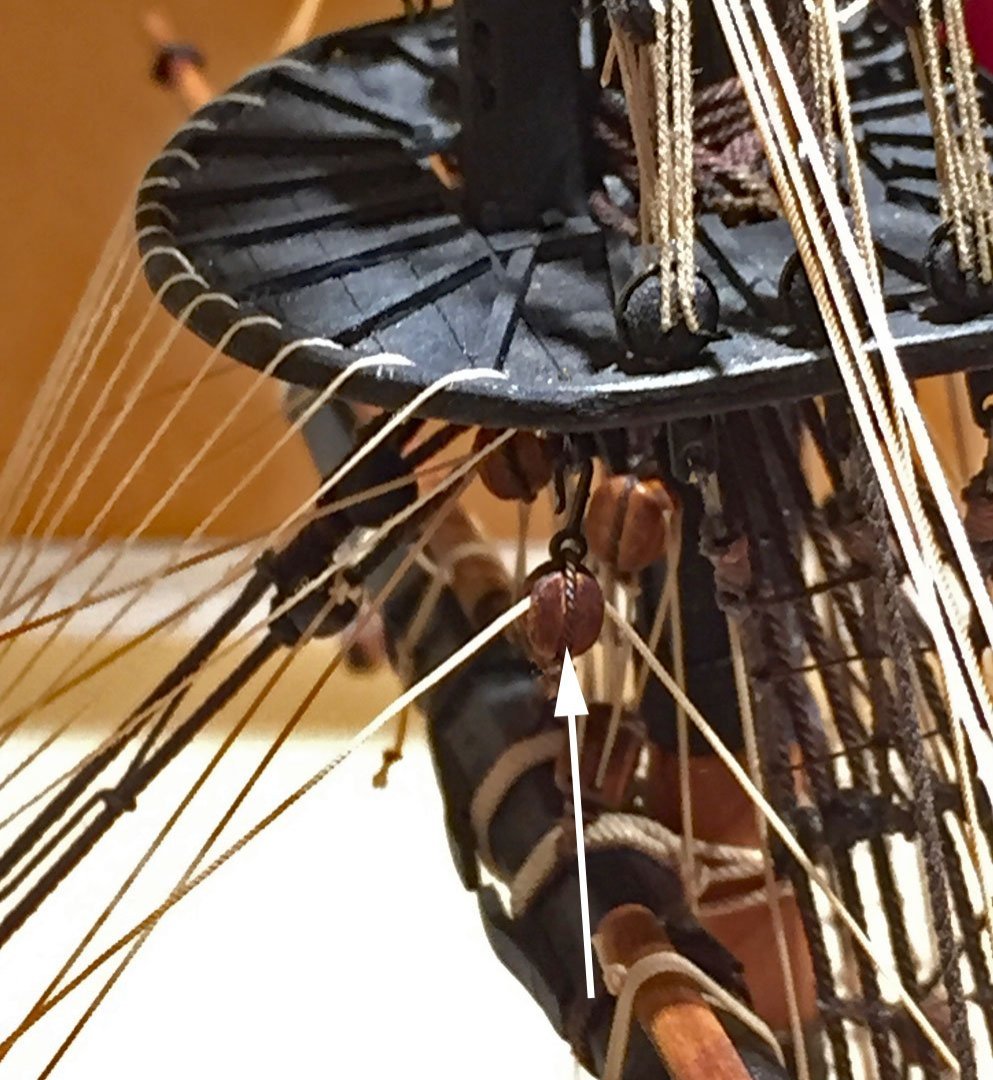
Here is the block for the spritsail topsail clue stropped to a hook that hangs from the eyebolt that I added to the foretop.

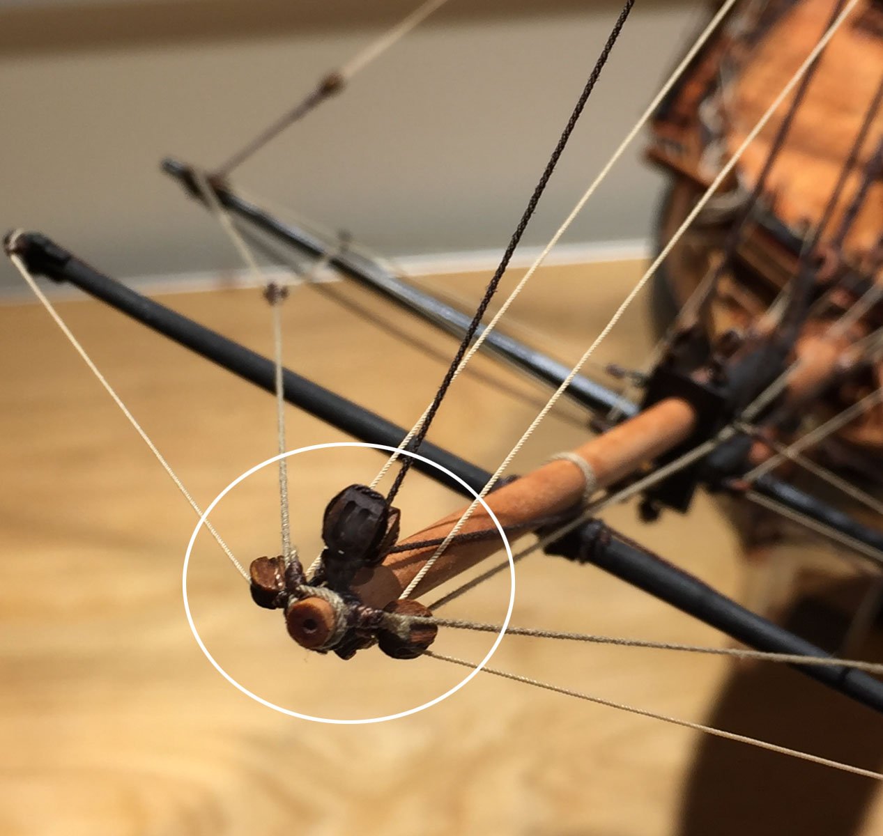
Speaking of additional sail rigging blocks: there are now five (5) rigged blocks at the very tip of the jibboom. I've added the double-sheave block- the darkest one - for the top gallant bowline; the line will lead back through the fairlead on the lower bowsprit and tie-off deckside.
The bowlines for the fore topsail require single-sheave blocks mounted atop the beeblock at the end of the bowsprit. These sail lines will also feed through the fairlead.

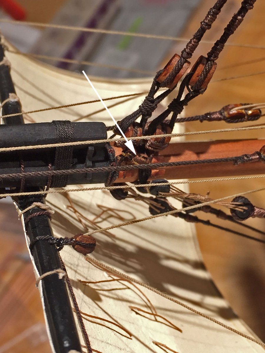
Last, but not least, the forecourse bowlines require two single blocks. These are mounted to the stay rigging lines near the open heart blocks that secure the foremast. These blocks are 3.0 mm, single-sheave. Blink, and they'll disappear! The arrow points to the port side one squeezed into the existing rigging. The bowlines will run unimpeded back through the bowsprit fairlead and terminate on deck like the other bowlines. I should have added these blocks earlier too. Oh well... build and learn.
A gulls eye view showing how I'm working "top down" with the sail rigging. Fore topgallant nearly rigged. Fore topsail is bent to its yard, but no clue rigging yet. The robands will be trimmed-off ala' the topgallant above it.

Another progress view of the foremast rigging with two of her three sails in various stages of additional rigging.
That's All For Now , Folks.
Back to more sail rigging prep. Sheesh.
-
6 hours ago, Ab Hoving said:
On behalf of my son and myself: thank you all for your kind words and the likes. It keeps a man alife.
Perhaps we should have published it after all. 🙂
Mr Hoving, I respectfully believe you should offer your unique creative efforts as a limited edition booklet. Small runs of high-quality printing can be produced by a number of vendors who specialize in these publications. Publishing your work as a hardcover, tangible physical asset would likely not be the most profitable venture, but something tells me this wouldn't be the primary motivation by yourself or your son. I'm also reasonably confident there is also a small market outside of this unique forum that would be interested in acquiring a physical copy of your creative works were it available. Please give my suggestion some further thought.
- mtaylor, bruce d, Rik Thistle and 2 others
-
5


.JPG.7ae330169ba72ab8ce58b8d0dc3c1a99.JPG)


HMS Sphinx 1775 by Hollowneck - FINISHED - Vanguard Models - 1:64
in - Kit build logs for subjects built from 1751 - 1800
Posted · Edited by hollowneck
grammar
The last sail and its rigging...
There will be a couple installments to this post as this last sail gets pre-made and then mounted to its yard. Hopefully, I'll be able to carefully fashion it into an acceptable shape resembling a "dangling sail."
After studying many 17th & early 18th century ship paintings (the photographs of the era), I decided to bend a hauled mainsail to Camilla's main course yard. I then tossed a full working sail into the waste basket that I'd made previously. I had also considered creating a fully-furled one, gasketed tightly to the largest yard on the ship before deciding to try something different.
Since my model shows her with a majority of her sails deployed and "at sea and in action" I decided to mount the partially brailed large sail across her midships. So many of the paintings I studied for reference showed this particular sail in this state (in many cases, also the foresail), especially in sea actions. I concluded that rarely would a patrolling ship have furled sails unless they were headed into very foul weather, anchored or in safe harbor.
Starting from scratch, I've created a main course sail with a single layer of silkspan, unlike her 10 other layered sails. This overall piece is roughly half the size (vertically) of a full sail. and is the full width of it's corresponding yard. The single thickness of silkspan will allow me to more easily shape it and then apply a fixative to the resulting folds to show a loosened sail, ready to be quickly hauled when needed. I liked the whole idea of this working sail ready-to-go, rather than one constrained. I've made furled sails but I've never attempted to create a partially hauled and brailed one. We'll see how this turns out!
To a single layer of previously colored silkspan (a leftover from Camilla's previous sailmaking), I carefully drew cloth panel lines in pencil to only one side (bow facing) and then added reinforcing tablings to the head and to a central portion of the foot. The roband ropes were added to the head and two holes for the bunt line cringles were added to the foot. To a portion of the foot and fully along the leeches I added a boltrope and the clue cringles as these will be prominently seen once the sail is in position. I anticipated the tabling reinforcements would be important as a single layer of silkspan would be subject to tearing and ripping easily with extensive finger manipulations to come at a subsequent mounting stage.
The sail's corners are folded over to show the approximate position of these clue corners once the sail is bent. The walnut dowel (from the kit) is shown simply for scale reference and is about the actual diameter of the main yard.
Camilla's Mainsail will be mounted here, rigged to its control lines and shaped to show a partially hauled sail.