HOLIDAY DONATION DRIVE - SUPPORT MSW - DO YOUR PART TO KEEP THIS GREAT FORUM GOING! (89 donations so far out of 49,000 members - C'mon guys!)
×


Dr PR
-
Posts
2,447 -
Joined
-
Last visited
Content Type
Profiles
Forums
Gallery
Events
Everything posted by Dr PR
-
Ratlines can be the last thing to go on the model. They are on the outside and all the other rigging should not interfere with putting on the ratlines. The opposite is not true. You will need to install the shrouds early on to set the masts in place. But there may be a lot of additional rigging to belay around the base of the mast. Ratlines can get in the way..
-
 Bug, Nice looking model! Figuring out how to run the rigging so the lines don't foul or chafe is tricky. Regardless of what the plans say, it has to work on your model!
- 419 replies
-
- 3
-

-
- Victory Models
- Pegasus
- (and 2 more)
-
Scale size questions
Dr PR replied to Desertanimal's topic in Building, Framing, Planking and plating a ships hull and deck
For older wooden vessels no one will ever know what their dimensions really were. They were built from experience, not accurate drawings. This is especially true for the hulls. They were built on the ways piece by piece and often the parts were hammered into place to fit with all the other pieces. The frames were fared with battens, not rulers, and certainly no two hulls were the same dimensions exactly. So don't sweat the small stuff! There is one trick that I have learned. For things that have straight lines or regular arcs/curves the designer/builder was working in some type of measurement units (inches, millimeters, etc.). You don't make something like a cabinet, deck house or hatch by just slapping together random pieces. So if the measurement you get from your drawings comes out to 10.082 units, it is probable that it should be 10.000 units. When I was making my CAD drawings for the USS Oklahoma City CLG-5 I found that the designers worked in common fractions of an inch - 1/16, 1/8, 1/4, 1/2, etc. So when photoguesstimating dimensions from photographs I just rounded off to the nearest fraction and things fit together pretty good in the drawing. A real problem here is that an older European vessel may have been designed to the inch/foot, but was it the English inch, or the French, Dutch, Danish, Swedish ... inch? They were all different! Another trick you can use when you don't know the actual real world dimensions is to use "relative units." For example, in a drawing/photo make the hull length at the waterline 100 units. Then measure things relative to the hull length. How many relative units back from the bow was the fore mast, main mast, etc.? How tall were the masts in relative units? Just make your CAD drawing in relative units and everything will be in proportion. Then, if you learn the actual dimensions of any part you can rescale the drawing to make that part the right size in real world units, and everything else will also be the right size. -
I have two headband magnifiers with plastic lenses. Both have a fold-up higher power lens and a permanent low power lens. I find this quick change feature to be very useful. I have another "head wearing magnifier" that has glass lenses with several degrees of magnification, but it takes quite a bit of time to change lenses. Also, the highest magnification lenses had an extremely short working distance, requiring me to get my nose into the work - not very useful! The glass may be better than plastic, but the inability to change magnification quickly has put the unit back in the box and on the shelf. For a long time I just used cheap off the rack eyeglasses with higher magnification than I normally needed.
-
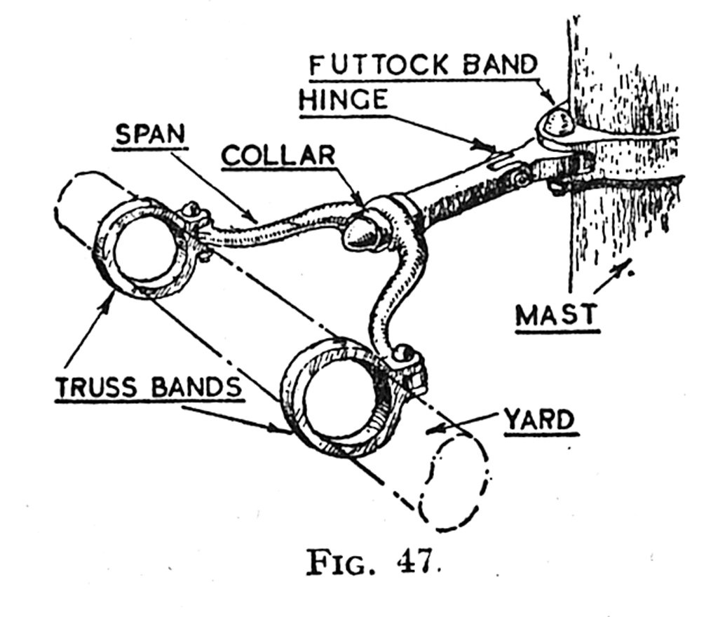
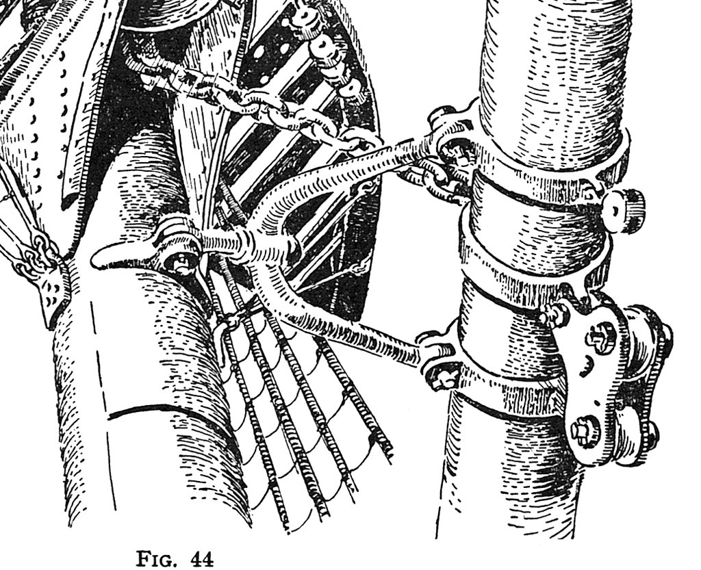
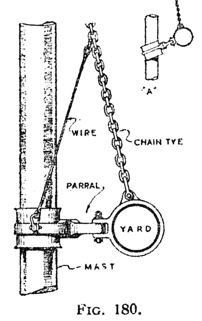
Not knowing which vessel, the time period, or whether it had wood or steel masts, we can only guess. But Underhill did publish several drawings of different truss types for lower yards in Masting and Rigging The Clipper Ship and Ocean Carrier. He also included a sail and rigging plan for a two mast topsail schooner (Plate No. 44) in Masting and Rigging, and another for the schooner Kate in Sailing Ship Rigs and Rigging (page 56). The frontispiece in that book is a very nice perspective view of an unnamed two-mast topsail schooner.
- 1 reply
-
- 6
-
-

-
Steamboats and other rivercraft - general discussion
Dr PR replied to Cathead's topic in Nautical/Naval History
The railroad ferry is of some interest for me. My grandfather was born in North Carolina about 5 years before the Civil War started. The war devastated the area so the family boarded a train headed west in about 1870. After a stop in Kentucky for several months they got on another train headed west. He told my Father that they crossed the Mississippi River at Memphis, Tennessee. The cars were loaded onto a ferry (but not the engine - it was too heavy). On the Arkansas side another engine was hooked on and they continued the journey to the end of the rails where the railroad was being built. There was a small railroad town named Atkins, Arkansas, and that is where they settled. That is where my parents were born. I have always thought it was an random series of events that brought them there. And the idea of crossing the river in railroad coaches on a ferry was interesting. I have researched this a bit, and I think the first railroad bridge was built across the Mississippi River at Memphis in about 1871.- 281 replies
-
- 3
-
-
- Steamboats
- riverboats
- (and 3 more)
-
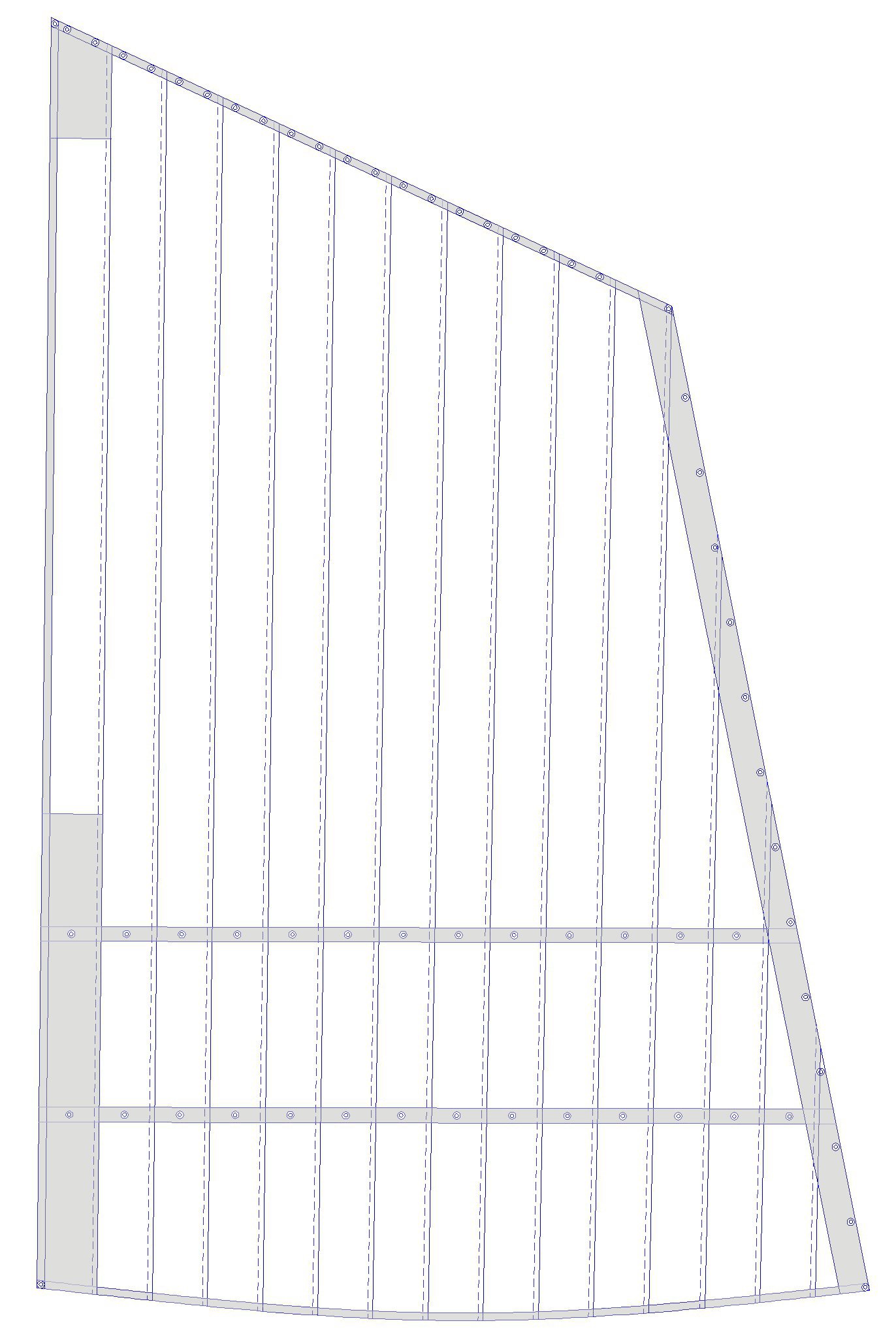
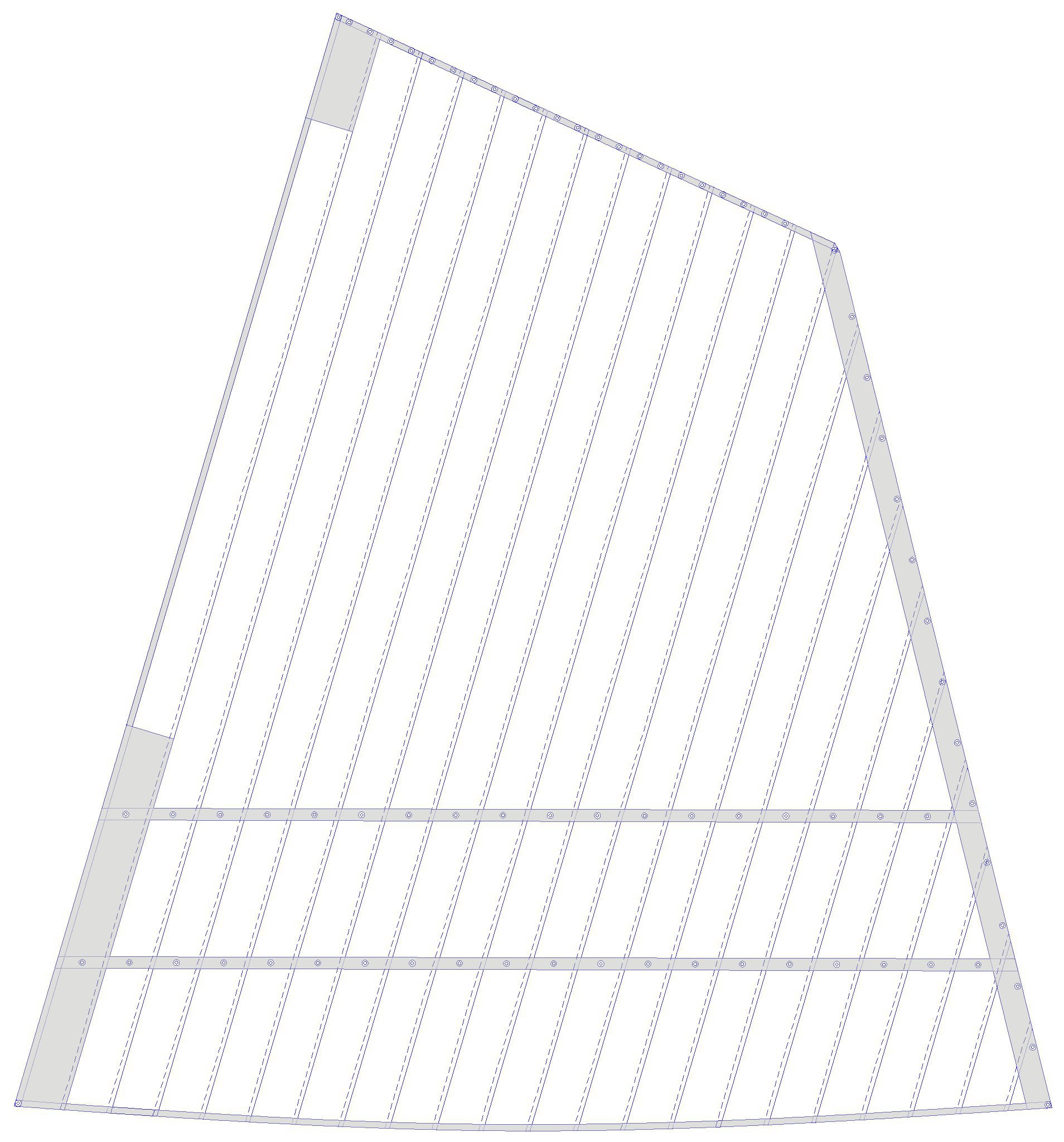
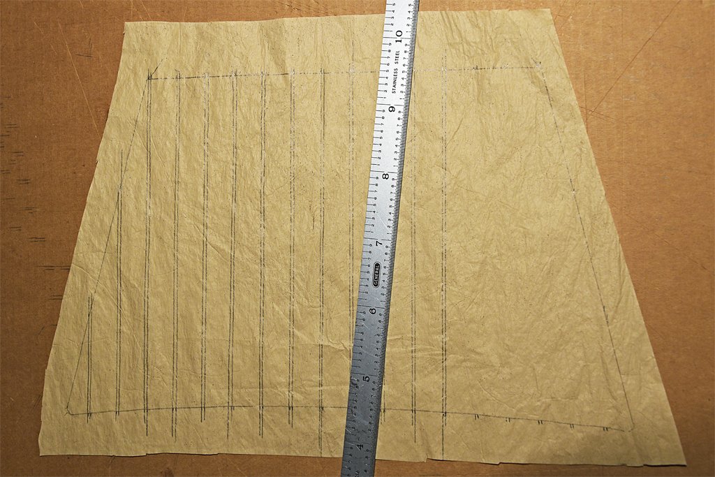
I have sails at last! A few have the tablings and linings but there still are a lot of details to add. The model is 1:48 scale, where 1 foot scales to 1/4 inch. The sail cloths were two feet (48 inches) wide, and that comes out to 1/2 inch scale. I have a metal ruler that is 1/2 inch wide and that really helped me to draw the lines for the cloths and seams. It was also very useful for cutting the sails from the larger sheets of material. I mentioned earlier that this sail material is pretty tough (when dry). I am able to erase any errors when drawing the pencil lines for the seams. However, although most of the pencil marks are removed it isn't easy to get the last bit, leaving a faint pencil line where it isn't wanted. I found a simple way to fix that - I just paint over the lines with the original buff colored paint I used to color the sail cloth.
-
Light ships are interesting vessels, but you don't see many models of them. Nice choice for modelling, and nice work! There is a lightship (Columbia WLV604) museum ship near me at Astoria, Oregon. I enjoy visiting it occasionally. It was positioned at the mouth of the Columbia River from 1951 to 1979. I wonder about duty on one of these vessels. A plus would be that you were near "home" all the time, but it seems that it would be monotonous duty. In the Navy we visited many ports - we really did see the world. On the Columbia they would have seen the fog.
- 299 replies
-
- 3
-
-
- lightship
- Feuerschiff Elbe 1
- (and 1 more)
-
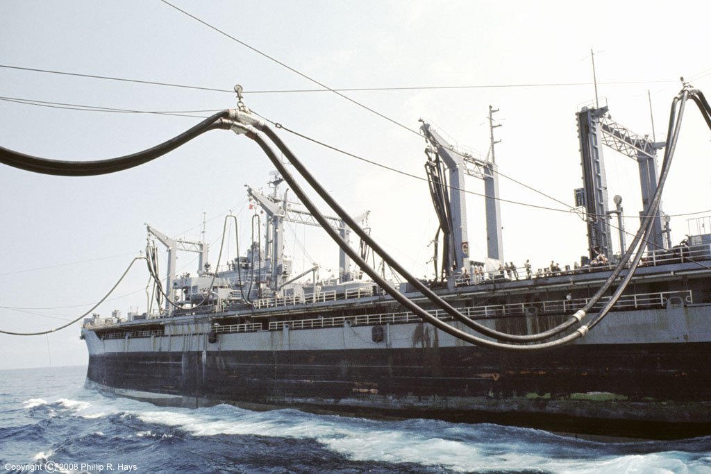
This "variable waterline" was called the "boot topping" when I was in the navy. It was a black stripe between the minimum and maximum load lines. You can see it clearly in this photo of an oiler running high and dry. When it was fully loaded only the very top of the black boot topping was visible.
-
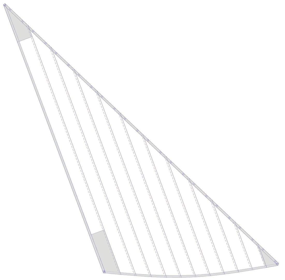
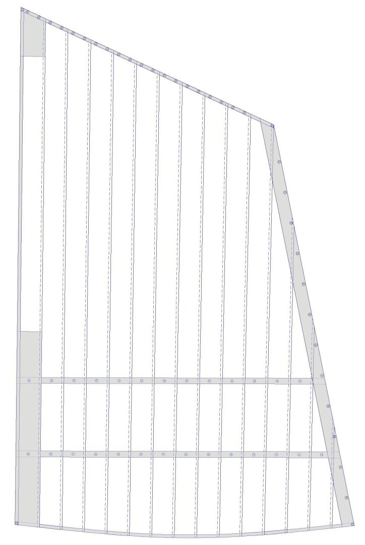
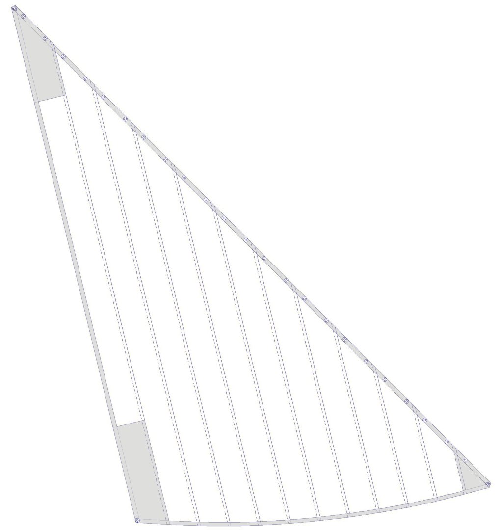
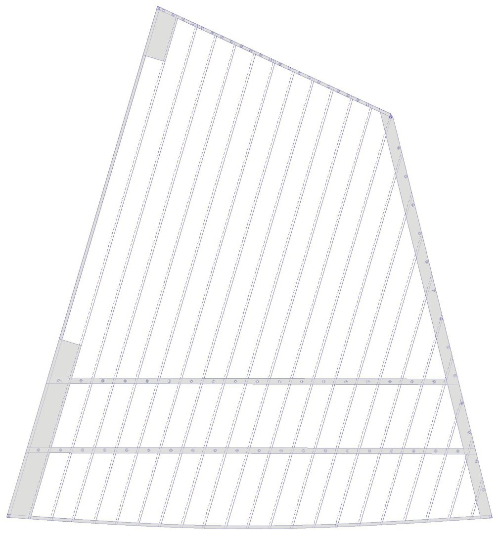
I have just plunged down the rabbit hole again, trying to learn how sails were put together. After reading through eighteen books describing sail making, I have concluded that whatever one author says another will disagree with it! All agree that since the middle ages sails have been constructed with parallel cloth strips (cloths) that are sewn together. How they were sewn together and how wide the overlap of the cloths was is not always agreed upon. But most authors agree that for the last several centuries in Europe and America in most cases the cloth width was 24 inches. Everyone says the edges of sails were lined with a bolt rope for added strength, and amazingly every author says the bolt ropes were attached to the port side of fore-and-aft sails and the aft side of square sails. This was the only thing they all agreed on! The outer edges of the sail cloths (head, foot, leech and luff) were folded over and seamed (hemmed) for added strength. This was called tabling. Most agree on this, but which side of the sail was the tabling folded to? Almost none of the books say which side! The few authors that dare to venture a guess seem to agree that the tabling was on the after side of square sails. Some say the tabling was on the port side of fore-and-aft sails, but one author says it was on the starboard side (mainly on modern British racing yachts). Some parts of sails were strengthened with extra cloth pieces called linings (although a few authors also call tablings linings). Most agree that linings were on the face of square sails (the opposite side from the tablings). Some say linings were on the port side of fore-and-aft sails (along with the tablings and bolt rope). The reef bands were sewn to the forward side of square sails and to the starboard side of fore-and-aft sails. But one author claims reef bands were sewn on both sides of the sail. Another says reef bands were sewn under the leech linings. But if the reef bands are on the starboard side of a sail that means the linings must also be on the starboard side, and not on the port! You have to love it when one author says white is black, and another says black is white. And which end of the egg do you crack first anyway? ***** And now there is Phil's way! On square sails the tablings are on the aft side and the linings and reef bands are on the forward side. On larger ships bunt cloths and additional reinforcing bands are on the fore side. The top lining (to prevent chafing against the mast tops) is on the aft side along the foot of the sail. For fore-and-aft sails the tablings and linings are on opposite sides like the square sails. Tablings are on the port side, Linings and reef bands are on the starboard. Now I can get on with making the sails for the model!
-
Such "fancy" detail is appropriate on showboats like yachts and royal barges. It is probably too gaudy for more pedestrian work boats. But for a model it depends upon what you are trying to do. It would be inappropriate for a model that is supposed to be faithful to the original vessel (unless the original had the same designs as the inlay). But for a display model that is intended to be more decorative than authentic it certainly is OK. It all depends upon what you want to achieve. It's your model, so do what you like!
-
Roel, We will take your word for it! We don't have to know how it works, and you are doing an excellent job of modelling it.
-
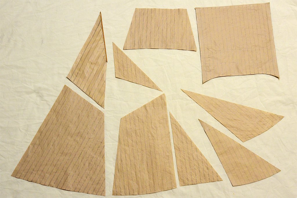
I have been sidetracked for a few weeks but am now back at work on the sails. I had to redesign a few of the sails. After reading about how sails are made I had to rethink the designs to make them as a sail maker would, using full 24 inch cloth widths where possible. I changed the flying jib and jib to have a whole number of cloths along the foot of the sail, as well as adding the roach (curved foot). For the fore sail and main sail the design was changed to have a whole number of cloths across the head and foot - and the roach was added. The reef bands were changed to 6 inches wide (1/4 cloth width) and two reef bands were used instead of just one (Lees, page 154-155). I plan to install the foresail and mainsail first, along with their gaffs and boom. They are lower on the masts and will be "inside" all the other rigging for the topsails. They will have to be tied to the mast hoops, so I want to get them in place before adding all the additional rigging that might get in the way.
-
Be sure to paint the 3D printed blocks. Some (all?) printing resins deteriorate with time and exposure to ambient UV light (especially sunlight).
-
Nice work Roel. Are you still serving on this ship? The piping is complex, but I think it is in the same league as the rigging on a large sailing ship. Everything has a purpose, function and place. I noticed the large "U" bends in the liquid pipes. Since they ice over I guess they must expand and contract quite a bit, hence the "U" sections to absorb the flexing?
-
John, Good progress! The model looks good with the sails. I will say again that you are fortunate to be able to visit the vessel and see the way the real thing is rigged. I have been waiting to see how you rigged the gaff sails. Since these sails are on the centerline and at the bottom of the masts - basically inside all the other rigging - I think I will rig them first, even before I put the ratlines on the shrouds. The fewer lines in the way while I am fiddling with the hoops and sails the better! In particular, I noticed that you pre-rigged the ties to the mast hoops. I am thinking about how I will tie the sails to the hoops. While I have tried to follow the rigging techniques shown in the books for most of the rigging, for the hoops I think I will just use a simple single loop and knot.
- 282 replies
-
- 1
-
-
- Bluenose
- Model Shipways
- (and 1 more)
-
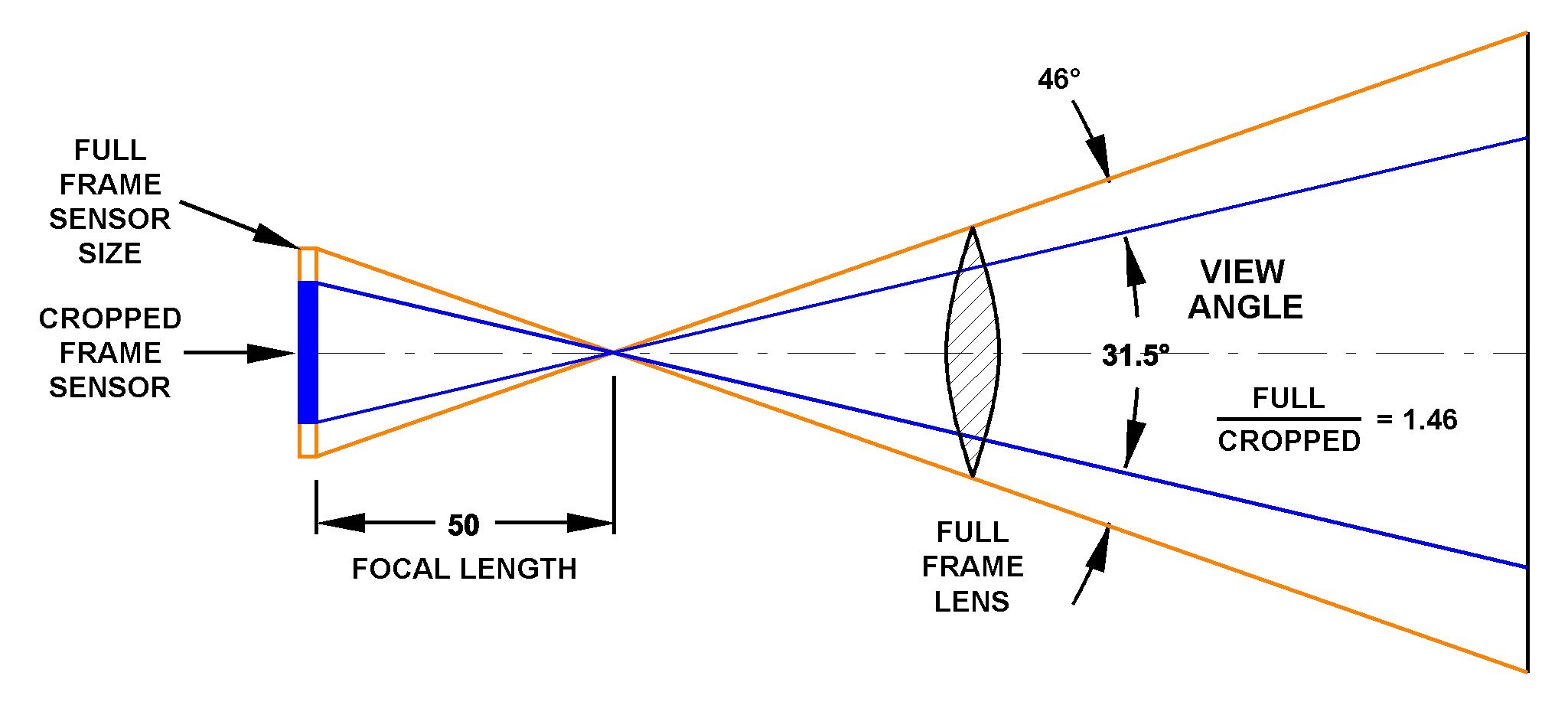
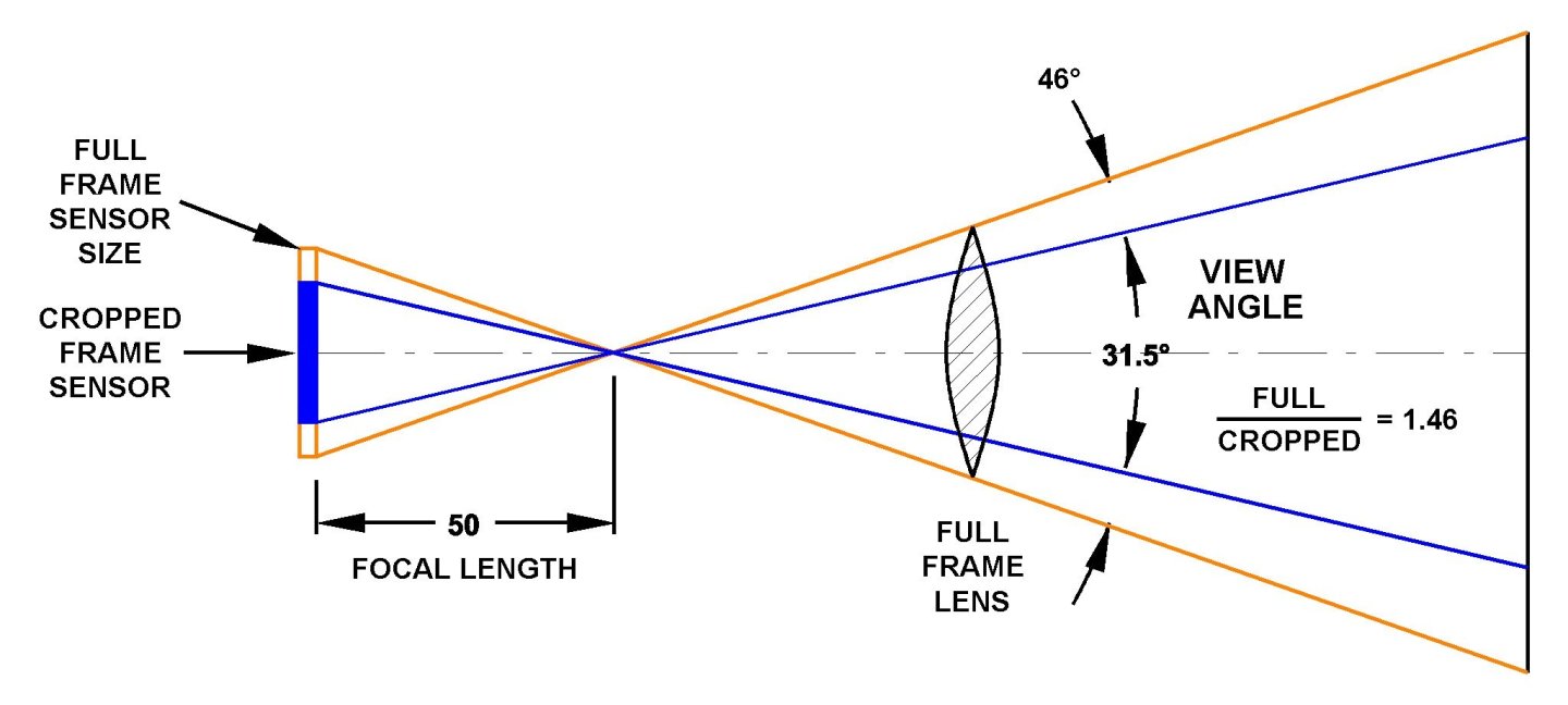
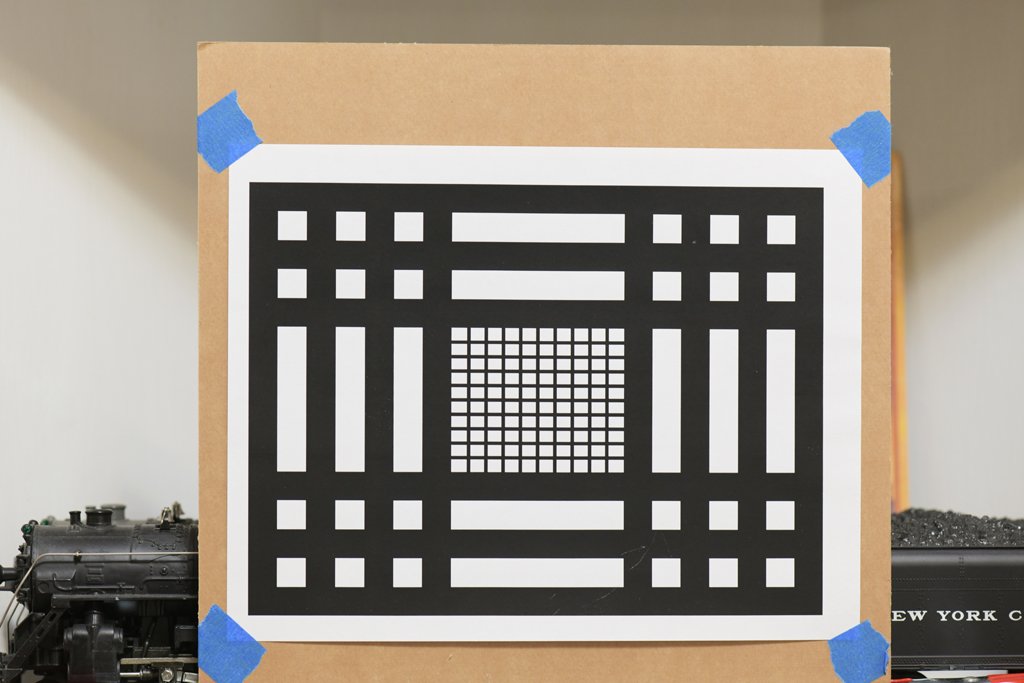
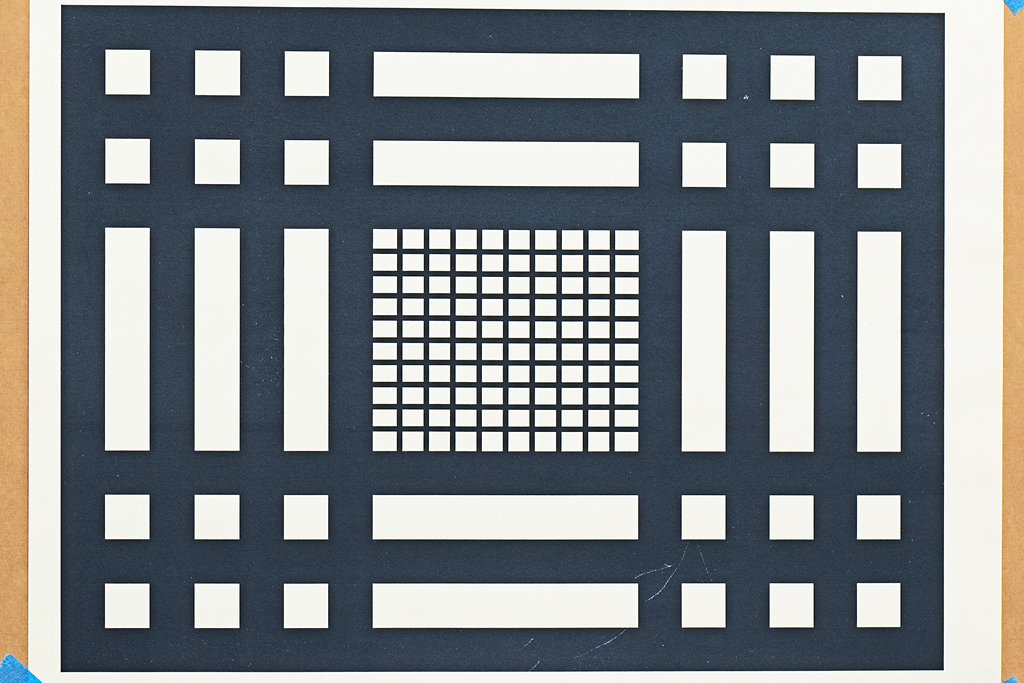
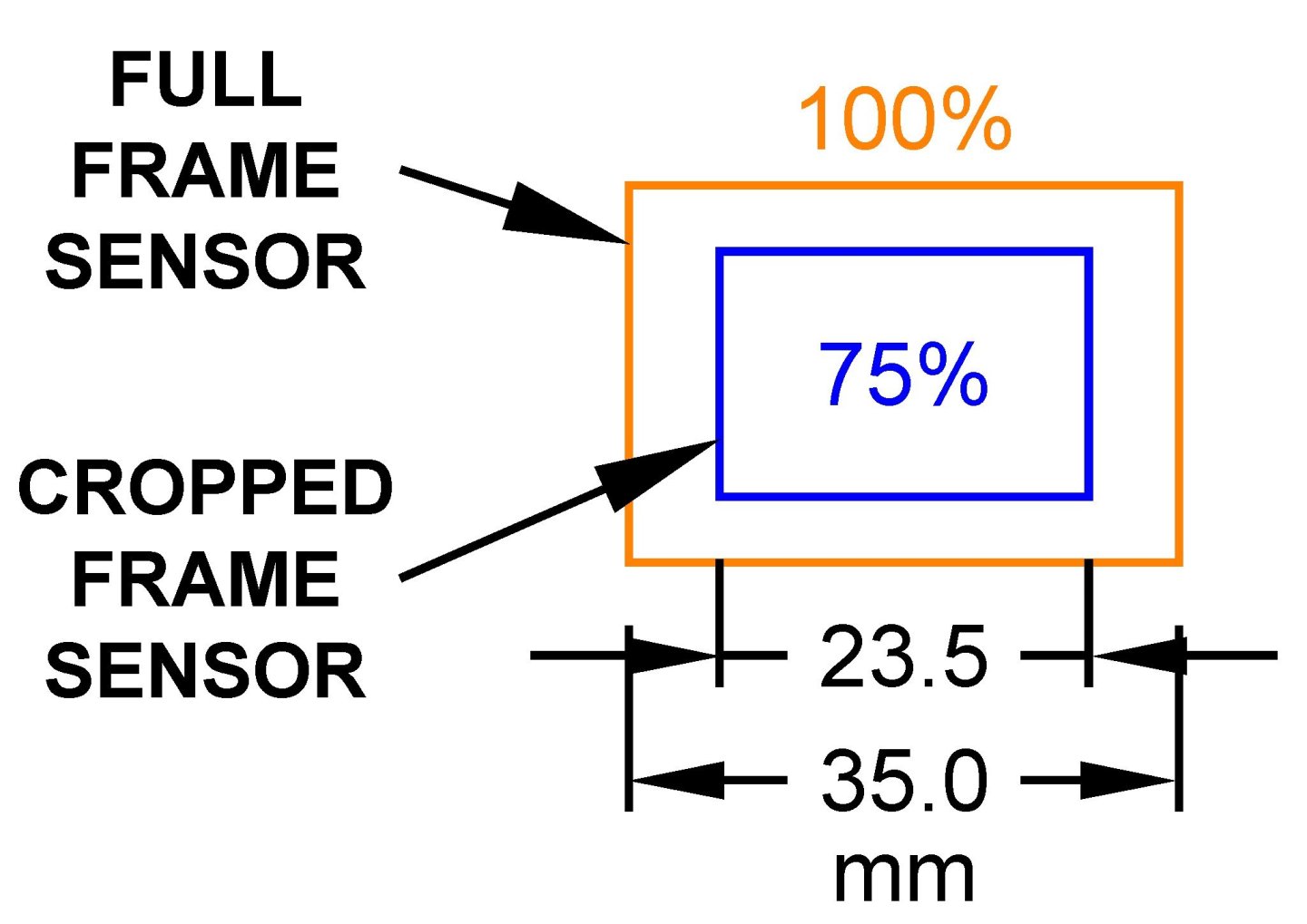
CAUTION: esoteric camera nerd stuff! We sometimes obsess about how many pixels our camera sensors have (mine is bigger than yours ...). But are more pixels ever worse than fewer? I have two principal camera bodies, the Nikon D850 and the Nikon D5600. The D850 camera body sensor has almost twice as many pixels as the D5600 sensor. It would seem the D850 should create higher quality images. But I was curious about the difference in actual image sizes for subjects photographed with the D850 FX camera body and the D5600 DX camera body, using the same Nikon Micro Nikkor 105 mm macro FX lens (a "prime" or non-zoom lens). The full frame (FX) D850 image sensor produces images with 8256x5504 pixels, or 45.44 megapixels. The crop frame (DX) D5600 produces images with 6000x4000 pixels, or 24.00 megapixels. So the D850 images have 1.89 times as many pixels as the D5600 images. This seems like an obvious advantage for the D850, producing images that can be cropped smaller to get the same number of pixels as a similar D5600 image that is cropped much less. But this isn’t the end of the story! Full frame (FX) lenses can be used on crop frame (DX) camera bodies. Because the DX sensor is smaller, if used with a FX lens only the center 75% of the image produced by the lens is used (for Nikon cameras - other manufacturers have different full/crop fame ratios). This narrows the view angle, and increases the effective focal length of the FX lens on the DX camera body by about 1.5. This means you can take a picture of an object to fill the DX picture area from about 1.5 times the distance as needed to fill the FX picture area. So from the same distance the image of an object will be much smaller in the FX camera picture than in the DX camera picture (using the same FX lens on both camera bodies). Which camera and lens combination actually gives more pixels for the object being photographed? A simple 1.5:1.0 comparison doesn’t work. The calculations are complicated by the fact that the pixel density on the FX and DX image sensors is different (the D5600 sensor has about 1.2 times as many pixels per mm2 as the D850 sensor). To answer this question I took some pictures of a test pattern with the D850 and D5600 camera bodies mounted on a tripod. I used the Nikon Micro Nikkor 105 mm macro FX lens on both camera bodies. On the DX D5600 body the lens is equivalent to a 157 mm lens. First I positioned the tripod so the test pattern image filled the D5600/105 mm picture vertically (left). Then I cropped the picture to include only the test pattern image (the outside of the outer black rectangle). The resulting test pattern picture was 5180x3904 pixels, or 20,222,720 pixels (20.22 megapixels). Then I shot the test pattern with the D850/105 mm setup on the tripod at the same position as for the D5600 shot. As you can see (left), the test pattern image does not fill the picture. After cropping the image to include only the test pattern, the resulting picture was 4632x3496 pixels, or 16,193,472 pixels (16.19 megapixels). This is 0nly 80% (0.800756) as many pixels in the test pattern image as the D5600/105 mm body and lens combination. From the same position, with the same lens on the two different camera bodies, the DX/FX D5600/105 mm setup produced 1.25 times as many pixels for the same object as the FX/FX D850/105 mm combination! So for more distant objects the DX body and FX lens gives greater magnification and more pixels for the objects being photographed. **** But what about close-up and macro photography? This is normally of more interest for model photography. For these situations you can position the camera close to the subject and fill the picture area with the subject. How much closer does the D850/105 mm combination need to be to fill the entire picture area with the test pattern? For this test I measured the distance from the initial tripod position where the test pattern filled the D5600/105 mm image picture. The distance from the test pattern to the focal plane was 146 cm (57.5 inches). Then I moved the tripod closer until the test pattern filled the frame on the D850/105 mm setup. The distance was 108 cm (42.5 inches). The DX body/FX lens combination fills the image with the subject at 1.35 times the distance for the FX body/FX lens combination. To fill the picture with the subject the FX/FX body/lens has to be only 0.74 times as far from the subject as the DX/FX combination. The D850/105 mm cropped test pattern had 7344x5499 pixels, or 40,384,656 pixels (40.38 megapixels). At this closer distance the 40.38 megapixel test pattern image in the D850/105 mm has twice (1.99699) as many pixels as the 20.22 megapixel picture on the D5600/105 mm at the longer distance when photographing the same object. So the D850 and 105 mm lens combination is much better for macro photography than the D5600 and 105 mm lens setup. **** I normally carry the MUCH lighter D5600 camera body (and FX telephoto lenses) when I am hiking and photographing distant subjects like birds and animals. The D850 is used in the "studio" (my kitchen) when I am doing macro photography of ship models, wildflowers and such. However, on special wildflower expeditions I will carry the D850 and the 105 mm macro lens into the field. EDIT: There is one special situation that is important for close up photography. Every lens has a minimum focus distance - the distance from the subject to the focal plane in the camera. This is a property of the lens, and not the camera body. You cannot move the camera closer than this minimum focus distance and get a sharp picture (at a given f-stop). At this minimum distance the image size produced by the lens is the same for both FX and DX camera sensors. With the Nikon 105 mm macro lens the image is the same size (1:1) as the real object. In this case the higher pixel density of the D5600 DX sensor produces 1.25 as many pixels in the image of the object as the D850 FX sensor. Macro photography is an art. But the best images are the result of applying the science of optics with the art of composition. Hope this is of interest to someone.
-
- 4
-
-
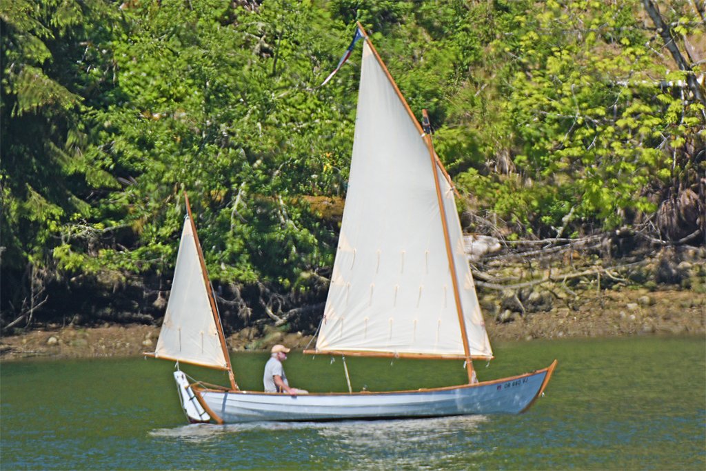
I like the reef points too. I think Wefalck may be right. This boat was on the Yaquina River upstream from the harbor at Newport, Oregon, an old (for the west coast) fishing town. There are a lot of old salts there and I like to think this guy just cobbled up his own rig.
-
I am curious what this rig is called: Looking through Harold Underhill's Sailing Ship Rigs & Rigging (Brown, Son and Ferguson, Glasgow, 1969) it looks like a "cat boat" with an extra shorter mizzen mast (ketch). He shows a "sailing lifeboat" with a similar ketch rig, but it has a fore staysail, the fore sail is loose footed and the mizzen sail is four-sides and has a spar like the fore sail. He also has a drawing of a "sailing canoe" with a similar rig except the mizzen sail is four-sided like the fore sail. A "fishing lugger" has sails similar to the sailing canoe.
-
Buntlines were rigged in front of the yard. The lines attached to the bolt rope at the foot of the sail. From there they ran up the front of the sail to blocks or thimbles attached to the front of the yard. After passing through the block/thimble the line passed over the yard to another block fastened under the top, above and behind the yard. From there the line ran down to the deck. There were several variations with different types and numbers of blocks. But I think in all cases the buntlines ran up the forward side of the sail and yard.
-
Propellers are intended to push a vessel through the water. The faster a propeller rotates, the greater the push. Increasing the size (diameter) and area of the propeller blades produces more push for a given RPM. The larger the diameter the faster the end of the propeller blade rotates at a given RPM. If the end of the propeller blade moves too fast it moves faster than water can move. As it turns it leaves holes or vacuum bubbles in the water. This is called "cavitation" and it causes two problems. First, there is a lot of energy involved and cavitation can rip bits off the trailing edge of the propeller - and even cause pits in the blade surface. This will create imbalance in the propeller, and that creates vibrations in the prop shaft that can wreck the foundations in the shaft alley and even destroy the turbine or motor turning the shaft. This is considered a bad thing. The second problem is noise. When the cavitation vacuum bubbles collapse they create a popping noise. This is like going into the reading room of a library and banging on a pan with a hammer. Everyone within hundreds of miles can hear cavitation. It is anti stealth! So if you can't have one big propeller turning really fast to get the push you need, the solution is multiple smaller propellers turning slower than the speed that causes cavitation. And modern "twisted blade" propeller designs were created to minimize cavitation.
-
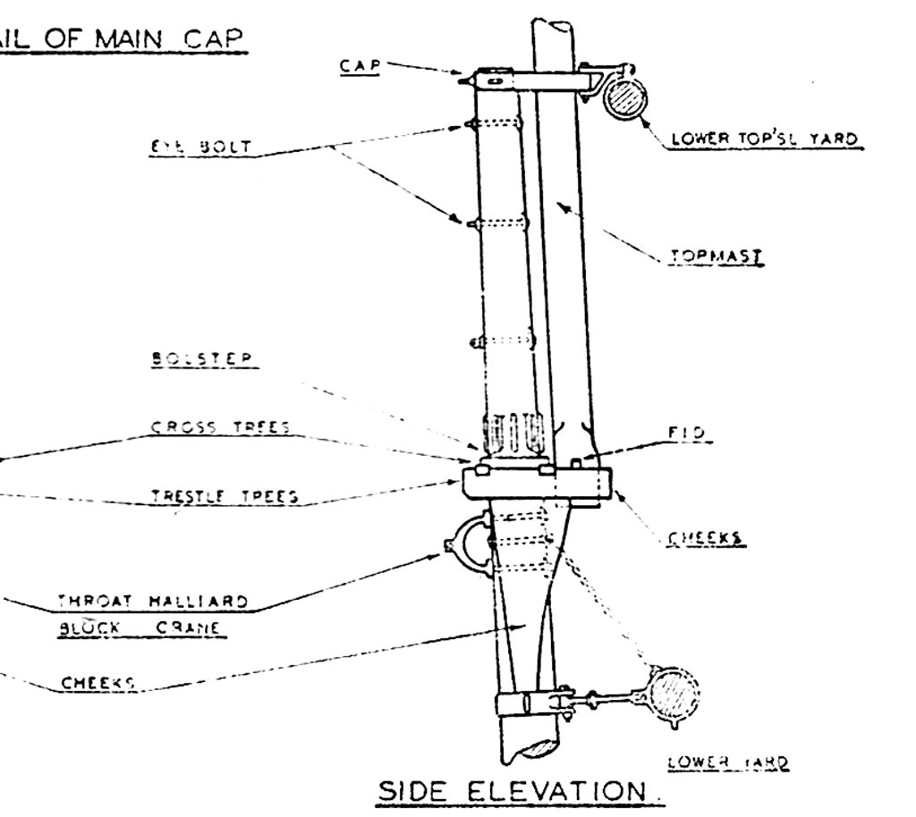
On larger ships the loading tackle (burton tackle) ran down from the topmast head (assuming there was a topgallant mast). On smaller vessels without burton tackle came down from the lower masthead.
-
Beautiful schooner, with a classic sail plan. It will make a great model!
-
SMS Karlsruhe by Wreck1919 - 1/100
Dr PR replied to Wreck1919's topic in - Build logs for subjects built 1901 - Present Day
Sascha, You have created a beautiful model! And it is even more impressive knowing you used simple tools, and you have great skill working with them. -
It is a beautiful ship, and the model deserves to be finished! How large is this model? What scale? From the photo looking down at the decks it is clear from the chair beside the model that it is pretty large! The ship had a lot of sails (the first photo). The square sails appear to be typical late 19th and early 20th century clipper rigs, but the mizzen mast is different. I knew that some vessels used a two-part driver on the mizzen, but I think this is the first picture I have seen. I am not sure what the upper "driver" sail is called. Underhill (Masting and Rigging the Clipper Ship and Ocean Carrier, page236) describes a "unusual rig" on the barquentine Transit that had three fore-and-aft sails on all but the fore mast. Underhill says these were called the "course," "topsail" and "topgallant." These were gaff sails and not square sails. The lower were two four-sided gaff sails, and the top triangular sail a more or less normal gaff topsail. I haven't see these terms used for fore-and-aft sails anywhere else. But the Transit was unusual in almost every way, so unusual terminology can be expected!