BANYAN
-
Posts
5,952 -
Joined
-
Last visited
Content Type
Profiles
Forums
Gallery
Events
Everything posted by BANYAN
-

HMCSS Victoria 1855 by BANYAN - 1:72
BANYAN replied to BANYAN's topic in - Build logs for subjects built 1851 - 1900
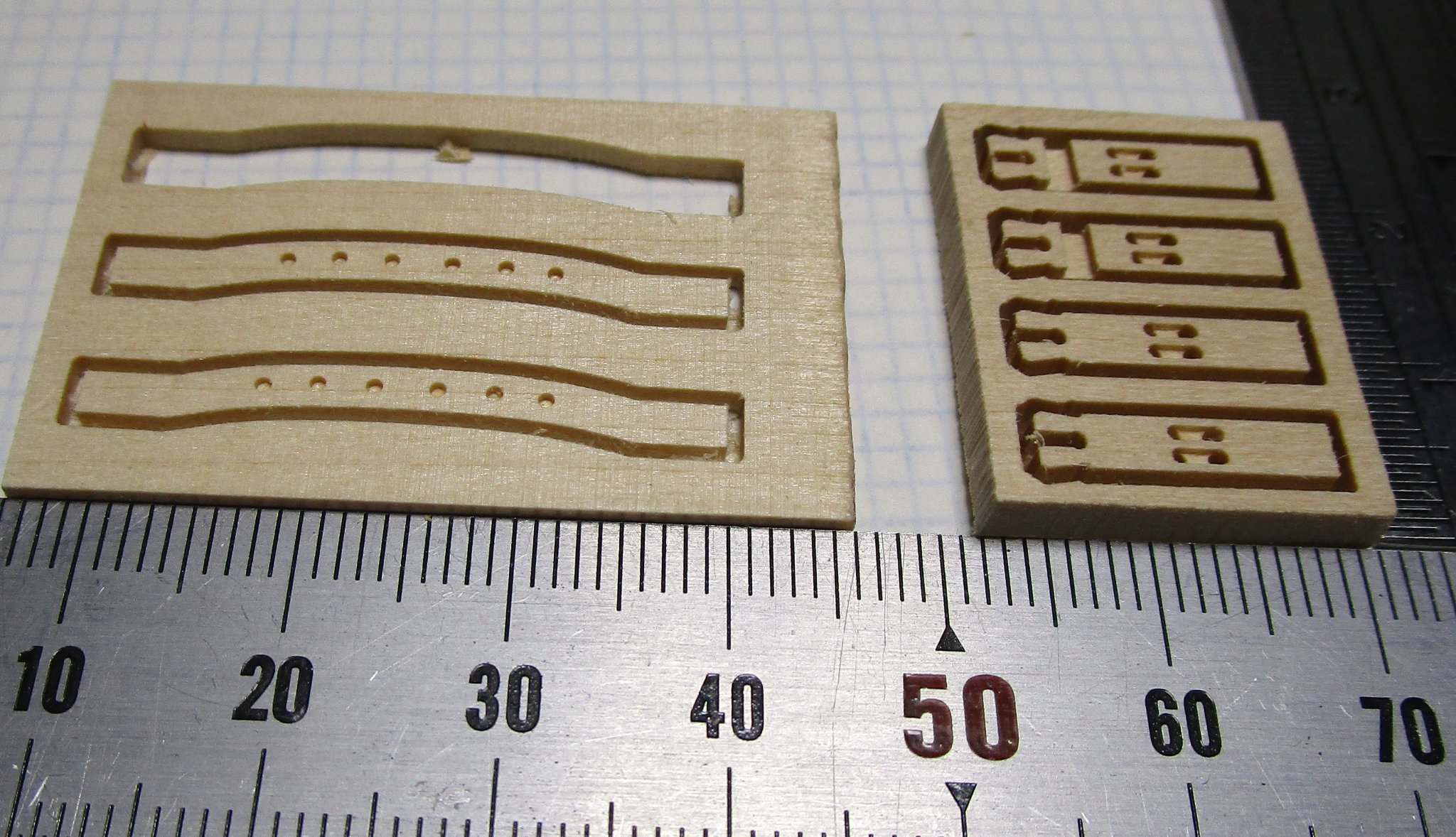
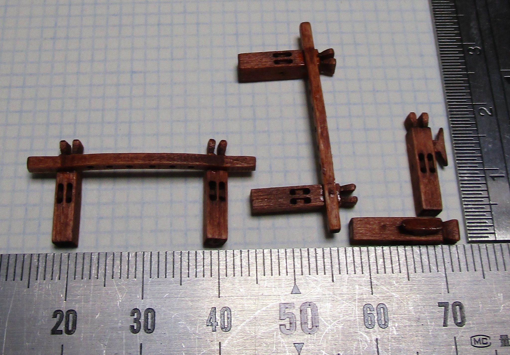
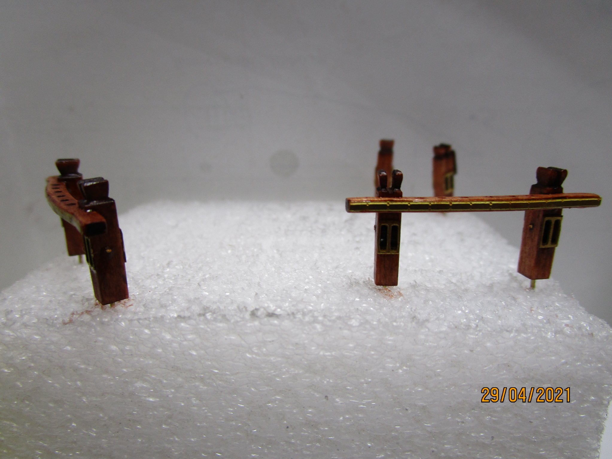
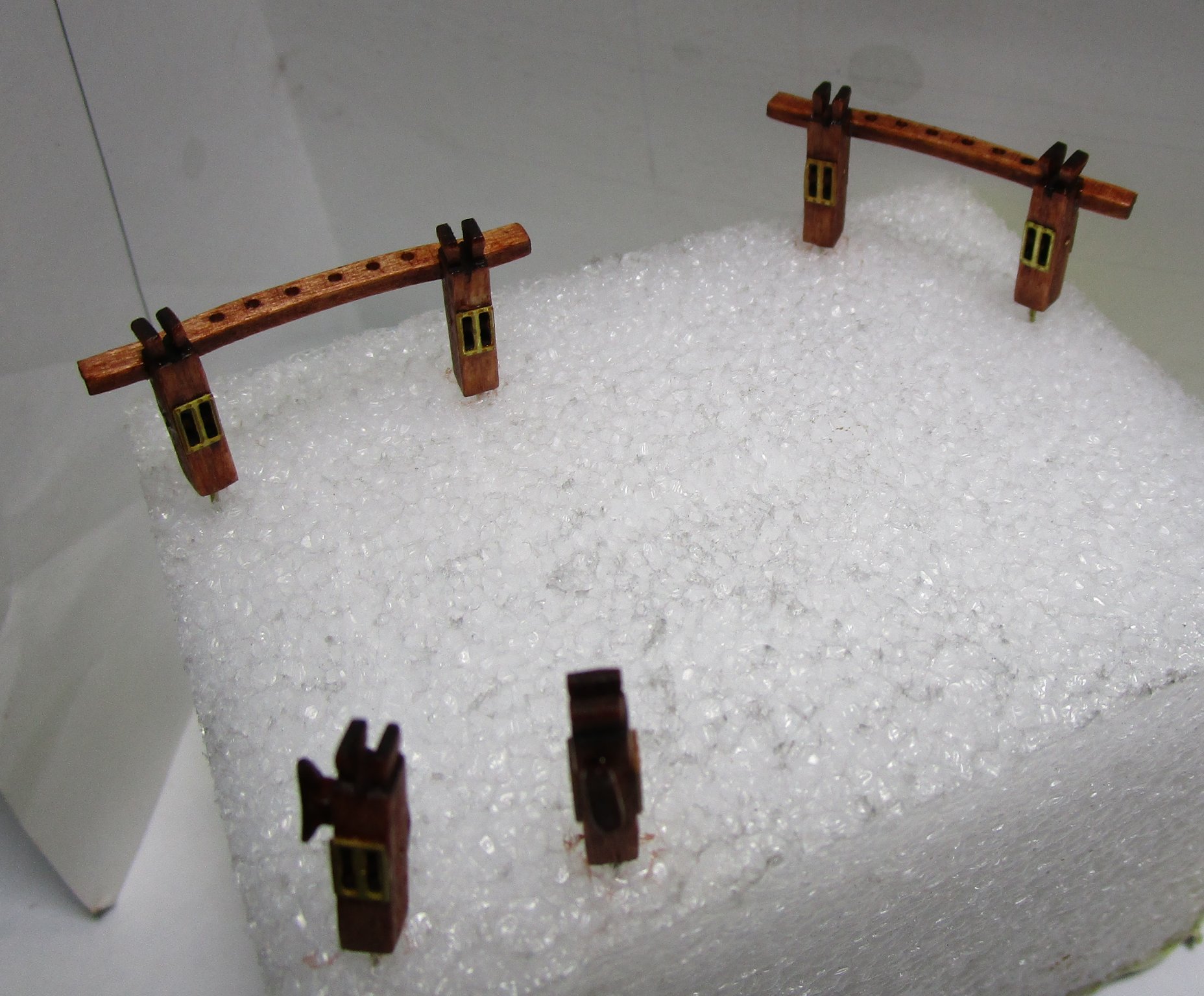
Sorry for the long delays and spasmodic posting of updates, but I have been somewhat distracted from the build by research. I am at the point I cannot progress until I finalise the rigging and belaying plans, and noting the unique rigging arrangements, this is taking a lot longer than I anticipated. Progress is good and I and in the final stages of that which has allowed me to make some small progress on the build. I have completed the lower spars and adding the fittings now. I will post some photos of them soon. In the meantime I have progressed the sheet bitts as shown below. I must thank Mike Shanks for his assistance in CNC cutting these for me. I drew up the plans for these and for the PE. Even at 0.2mm the PE looks slightly oversized, but the best I could get done locally. For reference, the brass strips along the cross-piece is only 1mm wide and I tried to simulate the screwheads (not that successful though). The single bitts are placed , one each side abaft the mizen, while the two sets with cross-pieces are placed before the fore and main masts. cheers Pat


- 1,013 replies
-
- 15
-

-

-
- gun dispatch vessel
- victoria
- (and 2 more)
-
YOUNG AMERICA 1853 by Bitao - FINISHED - 1:72
BANYAN replied to Bitao's topic in - Build logs for subjects built 1851 - 1900
A very fine example of your modelling craftsmanship, your workmanship is exemplary. cheers Pat- 257 replies
-
- 3
-
-
-
- young america
- Finished
- (and 1 more)
-
Great to see you back in the workshop Keith; I have missed your updates. Another fine example of your techniques, machining skills and execution mate, they look great. cheers Pat
-
YOUNG AMERICA 1853 by Bitao - FINISHED - 1:72
BANYAN replied to Bitao's topic in - Build logs for subjects built 1851 - 1900
Thanks Eberhard, makes more sense now. I buy a lot of their burrs and drills, so I will have a poke around their site again. cheers Pat- 257 replies
-
- 2
-
-
- young america
- Finished
- (and 1 more)
-
YOUNG AMERICA 1853 by Bitao - FINISHED - 1:72
BANYAN replied to Bitao's topic in - Build logs for subjects built 1851 - 1900
Your skills and build quality continue to amaze bitao; very much enjoy following this log. Eberhard, any chance of a photo of one of those rivet tools; I am having a hard time visualising what you describe I hope you don't mind bitao? cheers Pat- 257 replies
-
- 2
-
-
- young america
- Finished
- (and 1 more)
-
Those spars look good Keith, all starting to come together now. You just need to be a 'little' patient cheers Pat
-
I had wondered what had side tracked you Patrick; nice to see another well executed miniature for your collection. cheers Pat
-
Nice job Steven, the finish looks just like an iron casting. cheers Pat
- 740 replies
-
- 3
-
-
- Tudor
- restoration
- (and 4 more)
-
Looks good Denis, another for your collection of beauties. cheers Pat
- 1,090 replies
-
- 7
-
-
- showcase models
- vendetta
- (and 2 more)
-
I don't know how I missed this Druxey; I hope there is room for a late-comer to the party. Seeing what you achieved in other builds, this should be another beauty. I, and I am sure many others, appreciate the tutorial on how to develop a boat/building plug. cheers Pat
- 433 replies
-
- 4
-
-
- open boat
- small boat
- (and 1 more)
-
Looking mighty fine Keith, some lovely detail emerging. It reminds me I have to get back to the workbench - too much time spent researching the rig (but almost complete now). cheers Pat
-
Hopefully all will be sorted for you quickly mate; know where you are at as I have the same issue. cheers Pat
-
She is looking great Denis, a good job on the paint. cheers Pat
- 1,090 replies
-
- 6
-
-
- showcase models
- vendetta
- (and 2 more)
-
Very nice work; as Druxey says, a pity some of this lovely detail will be obscured. cheers Pat
-
A very nice build you have going here Brian, especially noting this is your first scratch build. The level of detail and clean work are admirabl. cheers Pat
-
Lovey work, and another successful collaboration between you both. Another very fine model in the making! cheers Pat
-
Greg, if it helps, I had a 3D print of 'Vampire' done at 1:350 through Shapeways. You can get the front deck assembly as a separate piece and you could cut away the unwanted bits? cheers Pat
-
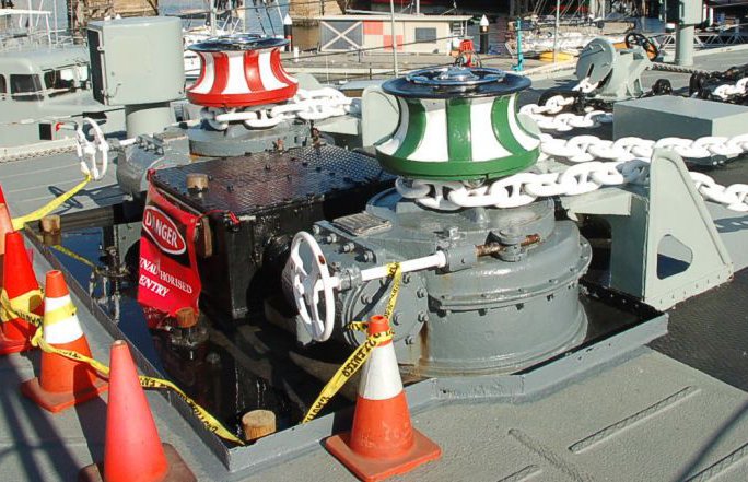
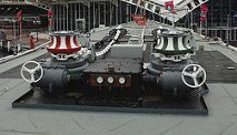
Just to be clear guys, it is not the V&W class but the Daring class I am talking of. These were the follow-on type to the Tribal and had a very similar hull form. This is a picy of the steam capstan arrangement on Vampire . The capstan stayed much the same even after the major upgrades in the late 60's; but, if you can find a picture of the pre-modernisation it might show a more-correct version.. Some of the surrounding structure, such as the cable ramps, drip/oil dam etc may be much diufferent but the steam winch is probably much the same - these were steam driven with the steam pressure dials ev ident in the central (black) box. cheers Pat
-
Again Greg, the Daring Class had a steam winch also; probably of the same type. I have photos of Vampire's capstan if that helps. Any of the 3D printed steam capstans of that period would work I think. cheers Pat
-
I can't state with definitive evidence, but the basic hull form of the Tribals look very similar to the later 'Daring' class, to which plan the Aussie Navy's Vampire, Vendetta and Voyager were constructed. It might be relatively safe to look at the plans of those ships (readily available) to establish the shape of a bow curve? cheers Pat
-
A lively discussion WRT to underwater fittings, the gudgeons, pintles, water intakes etc in my vessel (1855) were gunmetal.... Back on track though , the question related to upper deck equipment. In addition to the 'pretty work', such things as compass covers, especially the night covers, were usually brass and probably kept quite shiny - I know from experience that the 'morning watch' was brass work time, especially in the wheelhouse etc. Other items that sometimes attracted the polishing rag were the brass work on the Captain's gig (especially the brass in the rubbing strips), the ship's bells (forward and watchkeeping), brass ornamentation on such things as the bitts, companions and other upperdeck furniture. Some larger equipment in some 'period' ships also left the 'heads' and some fittings on such things as pumps etc brass simply as 'pretty work' - depended on the skipper (and if a warship, on the operational circumstances). As explained by John though, if it could be easily removed , it was stowed away in harbour if the public or other workers were embarking Just another pennies worth Pat