
HOLIDAY DONATION DRIVE - SUPPORT MSW - DO YOUR PART TO KEEP THIS GREAT FORUM GOING! (Only 24 donations so far out of 49,000 members - C'mon guys!)
×


BANYAN
-
Posts
5,937 -
Joined
-
Last visited
Content Type
Profiles
Forums
Gallery
Events
Everything posted by BANYAN
-
Hi folks, another unusual rigging item associated with Victoria's rigging. The Rigging Warrant, under 'Necessary Ropes' lists "2 (Stay) Mats for Yards. Has anyone heard of these before? A search of the usual references doers not give any clues (I have tried Underhill, Harland, Young, Biddlecombe, Falconer and others). Brady (The Kedge anchor, references 'thrum mats' for use on stays and yards as part of the chafing gear. Could these be the same thing? I have discounted them for the moment as only two mats are listed, and if these were to serve the same purpose many more would be required? Additionally, additional mats should have been listed for the crosstree horns and fitting to other rigging surely? cheers Pat
-

Rigging in 1855 - Need a Sanity Check Please
BANYAN replied to BANYAN's topic in Masting, rigging and sails
Hi Tony, thanks for the update and suggestions. I purchased a copy of the photograph from the SLV as a tiff and was able to enhance that in Photoshop. You are right about the 2+4 in the photo and I can only put that down to a rig change after Norman had passed command over to the Marine Survey (Hydro) RN Officers. Perhaps with the close-in to shore work they need a different rig? I am more convinced than ever that Norman set-up the rigging initially in a Merchant Service convention (as inferred in the correspondence), probably the same as he experienced when commanding Queen of the South. I used the wrong Manual title above, it should read 'Boy's Manual of Seamanship and Gunnery', written by Commander Burney 1871 for the RN. The description given in that corresponds nicely with what is given in the Rigging Warrant, and as such I am going with that rather than what is shown in litho 2 (not wrong, there is just no detail). In this set-up, the buntline was rove through the upper sheave of a shoe block (similar to a sister block but one sheave is turned through 90 degrees) then both running ends are rove (from aft to fwd) through a double block at the top or cap (still to be determined), with one end then toggled to the foot of the sail and the working part/end sent to the deck. The bunt whip was rove through the bottom sheave of the shoe block with a clip/sister/clasp hook on one end to clip onto the gullet becket as required, and the running part of the fall worked from the deck. Lever and Harland both state this was the preferred way in the Merchant Service. A very old fashioned way to do this, but apparently easier when minimum manned. There was no jigger listed but a bunt rope was. Yet to establish positively what that was for, but may have been set up as a centreline bunt whip but called a jigger (possibly the bunt rope) to avoid confusion when calling orders from the deck. The single block and hook sort of leans to this being the case. It also makes sense as having shoe blocks at the bunts would have made the glut difficult to lift and a centre jigger with the centre line Bunt Slab line would assisted in getting that up and onto the yard. The centre slab line was called a bunt slab line in the 'The Boys...' and informs that this was used to assist in hauling the gullet/glut of the canvas up and over onto the yard when the canvas had been got closer up during furling. The whips were further outboard so they need something in the middle. Starting to come together? cheers Pat -
Rigging in 1855 - Need a Sanity Check Please
BANYAN replied to BANYAN's topic in Masting, rigging and sails
Thanks for your responses and input John and Richvee. John: Your honour would not let you stoop to such depths The rigging in Victoria though was to merchant service standards. One Lockyer (RN Officer) resigned his position as Commanding Office (designate) he allowed Commander Norman to rig the ship to his preferences. Norman was from a merchant service background, and correspondence confirms he rigged the ship to the mercantile way of doing things. Yesterday, in doing a google search on a related rigging item, I stumbled on an answer to the way the bunt lines were rigged in "Boys Own Manual of Seamanship" which describes the rig probably used for the bunting lines (different to what I posted) which I will post separately in the next day or so once I tidy up a few loose ends. As the description so accurately reflects the components listed in the Rigging Warrant I believe this manual may answer more of my questions so will have a search today/tomorrow for the halliards also. This manual calls the slab line a 'bunt slab line which appears integral with the bunt line arrangement and DIRECTLY aligns with the other components. This is confirmed by Harland page 34 whereby, while not fully describing the whole rig arrangement, provided enough info to identify it, and he writes this was the preferred arrangement in the merchant service (Bunt/Slab line arrangements). I agree, goose winging does seem very plausible - thanks. The Boys Own manual suggests also aided the final lift of the canvas when furling in that being abaft the canvas eased the effort in lifting the 'bunch' up and over the yard. Richvee. A very similar arrangement with two running parts of the peak halliard - glad to see another example. The only difference to the ends being mine both went to a purchase rather than directly to the deck. Appreciate the input. I am hoping to find something in the Boys Own Manual of Seamanship and will update this thread when I have a bit more info. cheers Pat -
My sincere condolences on your loss Doris. What a wonderful tribute in completing this model for him; it looks magnificent. I have followed your build journey and as with everyone else can have nothing but admiration for your building skills and quality of your work. regards Pat
- 1,035 replies
-
- 4
-

-

-
- royal katherine
- ship of the line
- (and 1 more)
-
Rigging in 1855 - Need a Sanity Check Please
BANYAN replied to BANYAN's topic in Masting, rigging and sails
Thanks Tony, just to clarify a few things. The Rigging Warrant has proven very accurate (was compiled after the rigging had been fitted) so I think it reflects the actual fit and overrides anything broadly specified in the Contract. WRT to the second purchase - Nope, the throat halliard is listed separately with its own set of blocks. This purchase is definitely associated with the peak halliard. I have only seen one example of a double (two-ended) running halliard. This is in the Lore of Ships page 117. I raise it, as this is very unusual, but would work especially for minimally manned ships as Victoria was. WRT the slab line agree, but what I was trying ( ) to point out was that the foot of the sail, if the slab line is worked separately, takes the foot up the back of the canvas (to the back of the yard). As you infer, the three lines were probably worked together to bring the foot up almost horizontal. What I don't understand is why not then just fit it as a centre-bunt line? There must have been a reason for this which I cannot fathom. [edit - perhaps one reason for the centreline slab was to be able to lift the centre part of the course for visibility forward much as the same purpose as the tack tricing line in the boom foresail and mainsail.] cheers, and appreciate the feedback Pat -
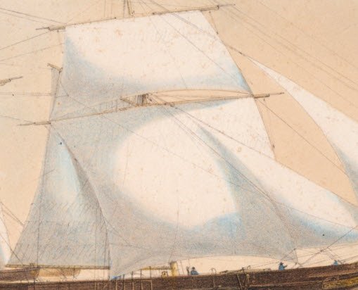
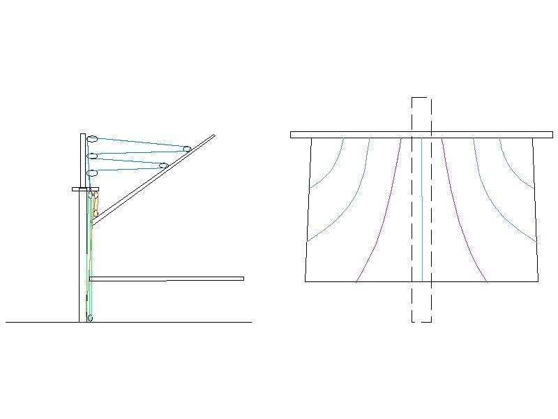
Hi folks, I am starting to make some progress with HMCSS Victoria's Rigging, but as mentioned in my build log, there were some very diverse differences in the rigging of ships in this era, mainly driven by the Captain's or Ship Owner's preferences. I have used the Rigging Warrant and the contemporary lithographs of the ship as my primary references, and in the main these agree with each other, but in some instances are very different to the general conventions of the time (as described by Fincham, Kipping, Underhill and Harland) - I have also referenced Lever, Campbell and others in trying to nail these rigs down. There are several rigging arrangements that, due to my lack of experience, I am not sure that I have interpreted properly. The first two of these are the Fore and Main Gaff/Boom Halliards, and the Fore Course sail handling lines. I would like to ask the more experienced and/or knowledgeable to offer comments on the first two of these as described below please. I have attached two images to assist as my descriptions as they may be a little difficult to follow The first is a crop of a lithograph showing the artist's interpretation of the rigging of the Fore Course. Note, just faintly, you can make out 2 x bunt lines and 4 x leech lines (plus bowlines which I have not addressed). The Rigging Warrant list 2x Bunt, and 1 x Slab line but NO leech lines. Both of these have proven quite accurate so far so I am betwixt which to use- my leaning at the moment is to combine them. The problem I have though, even the Specification called for 'light courses' (light weight canvas) I have not seen this arrangement whereby there are 2 x bunt lines as shown, but also 1 x Slab line on the centreline (Rigging Warrant). Has anyone seen this setup of the sail handling lines before? I am assuming all three were used together to assist the furling/reefing of the sail, with the centreline slab line used in conjunction with the bunt lines simultaneously. This arrangement would allow the sail handlers to not interfere with each other. Underhill infers the course usually had 3 x bunt lines? If the slab pulls the foot of the sail up the back of the canvass, while the bunts up the front of the canvas, would this assist or hinder the furling of the sail? The second image shows my 'very quick and dirty' drawing of this arrangement, and my interpretation of the Peak and Throat halliard arrangement for the Fore and Main fore-and-aft gaff/boom sails. The green line is the slab, purple the buntlines and blue are the leeches. The Rigging Warrant lists 3 x 10" and 2 x 9" single blocks associated with the peak halliard proper, but also associates a purchase made up with 2 x 7" single blocks. The imagery of the other lithograph (not the one above) shows that there was a running part emerging from the upper and lower blocks attached to the lower masthead, but does not show a connection to, or the purchase (probably as there is too much rigging in this area and it would have complicated the depiction of the other rigging. NOTE - I have not included the boom topping lifts etc to simplify this - I have also exaggerated the positioning of the gaff and realise when hoisting and lowering, the gaff was first made horizontal. I have assumed the three 10" blocks were fitted to through eyebolts in the lower masted (as described by Fincham and Kipping - 1855) and the 2 x 9" fitted to the gaff as configured by Harland, Underhill and others. Where this rigging arrangement differs from all the options illustrated or described by the various authors is that typically the standing end of the halliard is usually set-up to a becket on one of the masthead blocks. In this instance, the only way I can configure the halliard and purchase is as shown in my drawing. In this arrangement I have allowed two running ends to the halliard (blue) turned on metal thimbles to allow the tackle to be shackled to both running parts. The purchase fall running part belays to a pin in the spiderband of the foremast; the throat halliard standing part belays to the equivalent pin on the other side. The gaff tackle standing block is shackled to an eye on the centreline under the after crosstree, and the running block shackled to an eye on the upper part of the gaff jaws. The peak halliard purchase block will easily fit in the space of the lubbers hole abaft between the middle and after crosstrees. From a practical aspect this arrangement would work well as taking up the running parts with equal tension simultaneously would over come the issues with unequal strain on the fall parts using a single running part when first hauling on the halliard. As far as eliminating any alignment issues with the masthead blocks/running parts of the halliard, these blocks are normally staggered with the middle block/eyebolt on the centreline of the vertical axis of the masthead, and the other two blocks/through eyebolts offset either side of the centreline. This would then create a fair lead for both running parts of the halliard. Has anyone seen this arrangement before? Can anyone see any difficulties in such an arrangement from a 'mechanics' point of view? cheers Pat
-
Coming along very nicely Rob; starting to see her true lines now. cheers Pat
- 3,560 replies
-
- 2
-
-
- clipper
- hull model
- (and 2 more)
-
No problem Mike, happy to hear it was of interest. I use quite a few dental and jewellers tool at the scales I work with (1:72) as they are very well made usually and offer a lot to our hobby also I am no electrician or electronics guy, but I think there are inline thermal overload switch /fuse you can put into the main lead? This would then ensure you have no issues, especially if you are happy with what you have made. I found this which may help? protection-datasheet-2017.indd (oeelectrics.co.uk) cheers Pat
- 968 replies
-
- 4
-
-
- hahn
- oliver cromwell
- (and 1 more)
-
Mike when I experienced this issue I also tried a self-made drill very similar in concept to what you have made (based on a Russian modeller's ideas [posted in MSW generation 1]) I also experienced the slippage on the bit, and also found I did not have the level of control I desired. Based on the advice offered by Paul Budzic (Rotary Hand Tools for Scale Modeling - YouTube), I looked around for an affordable dental handpiece (micromotor). I found a very affordable one on eBay that had all the features I needed including variable speed, high top speed, low speed with sufficient torque, a foot or front panel controller, and most importantly it was light and easy to manoeuvre/handle the hand-piece even inside the hull (1:64). The machine came with a straight and contra angle end-piece and accepts the standard 2.3xx mm shaft dental drills, burs, cut-off disc etc. These are easily purchased through eBay but for better quality a chat with your preferred Jeweller's Supplier will give you an idea of what you can get. I have a full range of micro-drill bits ranging from 0.3 through 2.0 mm (anything larger I use my Dremel with standard small drill bits), some excellent carbon-fibre cut off discs and burrs etc. Some of these can be expensive but the quality is great and last a lot longer than the cheaper versions. You may wish to take a look at such an option? cheers Pat
- 968 replies
-
- 5
-
-
- hahn
- oliver cromwell
- (and 1 more)
-
HMCSS Victoria 1855 by BANYAN - 1:72
BANYAN replied to BANYAN's topic in - Build logs for subjects built 1851 - 1900
Thank Keith B, and wishing you and your family a safe and happy Christmas; with hopefully a better 2021. Keith A, that is the hope. Fingers crossed these vaccines will bring a halt to this horror. cheers Pat- 1,006 replies
-
- 3
-
-
-
- gun dispatch vessel
- victoria
- (and 2 more)
-
Thoughts are with you mate; keep at it. Stay safe Pat
-
Greg that channel down the middle is probably the track part of the helicopter assisted recovery system (used to pull it into the hangar. Have a great Christmas. cheers Pat
-
Just my two cents (sorry pence) on those electrical 'boxes'. Keith, they look suspiciously like the bronze 'junction boxes' used in RN warships (well the Aussie variants anyway). Used as the name says as a junction box so it is possible it connected wiring running inside the mast to the external part of the wiring. A similar type of box but with larger ports/sockets in them were also used to connect upper deck portable electrical gear/equipment such as lights, pumps, grinders/descaling hand (electrical) tools. We used to call that type of socket connecter a 'donkey d***' May or not be the same sort of box? cheers Pat
-
Most ships, especially warships, use a self polishing paint on the hull bottom these days. If there is algae at the waterline it is more than likely she did not move around much recently (like sitting alongside during, or waiting for refit). This type of paint goes on one colour and is 'polished' off as the years go by - when it gets to the last colour it is time to have the bottom cleaned. cheers Pat
-
The trunnion caps are kept closed at all times otherwise the barrel might jump from the carriage. The whole gun (barrel and carriage) is trained using the bars to move/lever the rear of the carriage. cheers Pat
-
Wishing you a safe and happy festive season Keith, I hope your family remain safe and you can catch up again soon. Following your anchor discussion with interest as a similar arrangement will have been used with Victoria's anchors, although hers were stowed outboard. cheers Pat
-
Hi Ilhan, that is very nice detail. Thanks for posting the sequence of photos showing how you you are doing this. I assume you will be bending the davit arms to a curved arc extending outboard at some stage. I am following with interest as I need to do something very similar at scale 1:72 and you are showing what can be achieved. cheers Pat
-
Terrific detail Alex; so nice to see you back making sawdust again. cheers Pat
-
Fantastic build mate, the display case with the backdrop is just what was needed for the final 'flourish'. cheers Pat
-
Nice detail Keith; Eberhard has said it all. Your upper deck is certainly coming to life. cheers Pat
-
Brian, as Keith says, who can challenge unless they have a 'wayback' machine. For my two cents worth though, but I have no experience with US ships at all, is that if the museum model has a red hull, then you would like to think they researched this properly? My leaning would then to be to follow the museum model (unless you are aware the model was not that well researched?) cheers Pat
-
HMCSS Victoria 1855 by BANYAN - 1:72
BANYAN replied to BANYAN's topic in - Build logs for subjects built 1851 - 1900
Hi guys thanks for looking in and I should have posted an update on what is happening. The lack of posts results from a few reasons, chiefly that after a 4 month hard ( I mean very very restrictive) lockdown here I had to put the model aside for a while to catch up on all the Spring/Summer chores and the 'honey please do' list At least the outcome of the lockdown has been great as we have all but eliminated any community transmission of covid for the time being. The other reasons being tied to RESEARCH (ugh, it is becoming a chore now ) I cannot progress the remaining deck furniture until I finalise the Rigging and Belaying Plans. I am about 25% into that. In the meantime the lower masts have been made and I will soon post an update on the 'tops' which are also of a very 'different design to those commonly seen, even in this era. Unfortunately analysis of the available imagery when compared with the Rigging Warrant results in a rigging and belaying plan that does not align with those offered by contemporary and other authors such as Kipping, Fincham, Underhill, Crothers, McKay etc. As such I am having to follow each line individually in a 'virtual' configuration to determine the likely rigging arrangement and belaying points such that they do not interfere with each other and conform with the imagery. One example being that unlike the options proffered by the authors, the topmast backstays were configured the opposite of the usual rigging practices in that the forward backstay was set-up as a breast (permanent not temporary) and the after set-up as a standing backstay (preventer) to a rigging screw in the channels. Anyway more on all of this as I get to grips with the rigging in the new year. Hopefully the new year will bring a return of the 'mojo' I need to complete this. cheers, and again, thanks for your interest Chuck and Keith. Pat- 1,006 replies
-
- 8
-
-
- gun dispatch vessel
- victoria
- (and 2 more)