Jump to content

BANYAN

SPECIAL CONTRIBUTOR
  • Posts

    5,781
  • Joined

  • Last visited

Everything posted by BANYAN
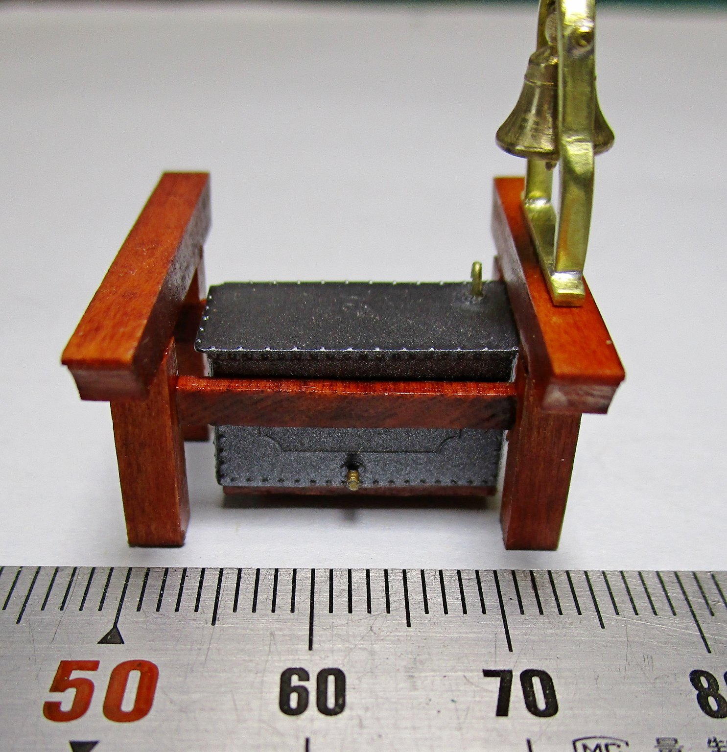
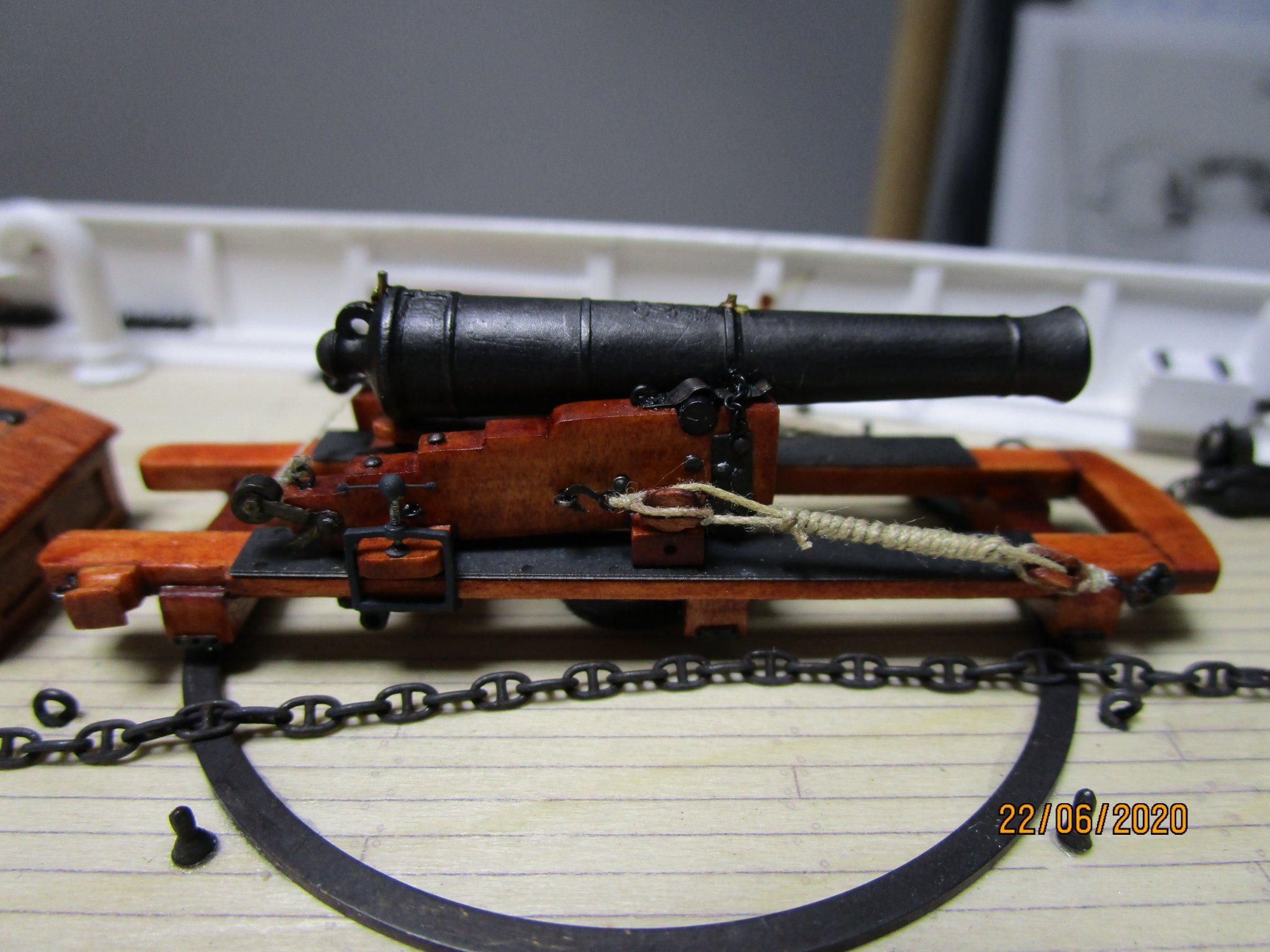
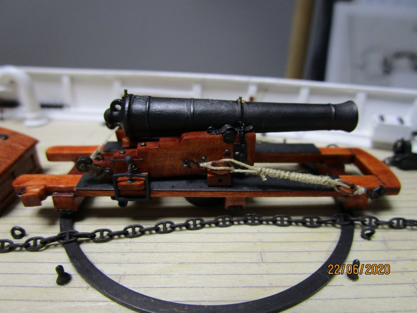
  1. Bump - any ideas anyone?
  2. Very nicely constructed hull Pavel, look forward to your log. Another warm welcome. cheers Pat
  3. Rob, you lucky devil - I wish I could run into a shipwright or expert like that re Victoria, even if just for the conversation (I understanding you are talking with Michael but even so, has had the benefit of the other discussions and knowledge to pass on) - envious! Seriously though, that is great news for you. cheers Pat
  4. Hi [nickname?] I have been doing both methods of finishing PE you mention for some time, and this response reflects my experiences only - may be alternate answers forthcoming The brass stock used with PE is sometimes covered with a protective coating, or has some residual chemical coating, that needs to be removed. I find that cleaning with a fibre scratch pen (like a propelling lead pen) helps greatly, especially if the PE is to be soldered also. If painting, I also found that using a metal etch solution (such as those from Mr. Metal) helps the paint adhere. Even if well cleaned and undercoated with a good quality primer, without such a metal etchant, I also experienced the same scratching issues. If blackening, here cleaning is very important. I also scratch clean with the fibre pen for this process to ensure I remove the coating. Your cleaning is OK I think, but the main issue I see here is the strength of the blackening solution you are using. I have found it is better to use a diluted solution. I start with a 50/50 demineralised water/birchwood casey blackening solution; however, with some metals an even weaker solution creating a 'slow baked' patina gives a better result.. I usually give the part about 5 minutes in the first dip then check progress. Even with the best cleaning sometimes, parts of the PE fail to take the patina initially. If I see areas not blackening, while still wearing rubber gloves - nitro type, not the powdered ones) I give the affected areas another clean with the scratch pen. You have to be careful with PE as you have probably found already, some parts are very delicate. It is then put into the blackening solution, then checked again after a few minutes. Sometimes I have had to do this three times. The results I get are a nice grey iron like patina initially. The longer, and more often you put the parts into the diluted solution provides a deeper colour. Between baths, once I have a full coverage, I wipe/polish with a paper towel to see what the depth of colour is. Once happy with the colour, rinse well under flowing fresh water and polish dry. I hope this works for you. Happy modelling. Pat
  5. Ok, now that the lower lifts are resolved; here is another one that bamboozles me a little. - The Topsail Yard Lifts. While discussing this, please note this yard was fitted with an iron parrel on Lt. Green's patent as shown by Underhill. The RW lists single lifts again but the lift itself having no associated block but does have a thimble and a common hook. I am trying to figure out which end the hook would be. Lees says a soft eye was formed outboard and placed over the yardarm (lower yard had an iron band and I would think this yard would also?). This would put the thimble with hook on the inboard/running part. There is a tackle with runner also listed. the tackle is formed with two 6" single blocks, and the whip (if the runner, if that is what it is) has a thimble and another 6" single block. I am basing this on the convention used in the RW that has the tackle immediately following the line with which it is associated, and the 'tackles' are grouped/bracketed. This seems an extraordinary amount of 'power/mechanical advantage' for a lighter yard, which would be restricted in canting by the iron parrel? This yard is also hoisted and lowered with the chain tye to a wirerope halliard fitted to a winch, so I doubt this amount of power would be need to assist in hoisting the yard. Lees, Underhill, Harland and others I have looked at, do not appear to discuss any arrangement like this (unless I have missed something). Surely, for this to work (cant the yard) the parrel would have to be released I think. How often was the topsail canted? Am I missing something very obvious? Underhill mainly talks of standing lifts in this era where the inboard end was belayed or seized to the middle shroud of the gang (des not state where); but, then why associate tackles if a standing lift. And, why such a powerful tackle for a lighter yard? I understand some power would be required as this yard does not have a central pivot point. Any pointers, suggestions or comments most welcomed. cheers Pat
  6. Thanks guys, even though that was the only workable solution I could see that incorporated the listed fittings in the Rigging Warrant, I was concerned with the 'weight' . Much appreciate the reassurance, this would have worked. cheers Pat
  7. Hi Bruma, Underhill (Masting and Rigging the Clipper Ship and Ocean Carrier), page 142, writes that the downhauls were led through lizards seized to the hanks along the luff of the sail. This then would have them fitted on the hanks rather than running on the stay; the hanks then ran up and down the stay. He illustrates this in figure 22 of the book (sorry due to copyright etc, can't reproduce here). cheers Pat
  8. Hi again folks, another conundrum I am trying to resolve. I would greatly appreciate any thoughts on the following. The Rigging Warrant (RW) for HMCSS Victoria lists lifts single associated with a 7" double block and a clip hook with each, lift tackles associated with a 7" single block each, and a Jigger. Lees page, 69 explains the jigger, which was removed after the yard had been hoisted into place, so it is not relevant to this discussion. Of note the RW notes specifically that the lifts are 'single' which ties in with Underhill's description of their rigging. Underhill, page 157, informs that lower yard lifts were always rigged as running rigging and provides some guidance that largely aligns with the RW listing; except using single blocks with the lift, BUT, more importantly utilising a purchase. Based solely on using the listed rigging fitting associated with each lift and tackle ONLY, the arrangement probably used in Victoria, will have had the 7” double block shackled forward on the sides of the upper cap. The purpose of the outer sheave has not been determined but may have been used to lead the associated top rope when fitted. The single lift will have been made up with the outer end, or standing part turned on a thimble, and spliced back into itself. This end was then shackled to the upper lugs on the yardarm band. The lift was then led up through (fore-to-aft) the inner sheave of the 7” double block fitted on the respective side, forward on the lower mast cap. The running end of the lift was also formed in a hard eye with the thimble rove through the eye of the clip hook. The running part of the lift was led down through the lubber’s hole in the lower top and hooked (and moused) to the running block of a whip. To allow sufficient working length, the end would have terminated just below the lubber’s hole with the yards set horizontal. A hard eye was sliced into the standing end of the whip fall which was shackled to an eyebolt in the deck abreast the mast near the partners. The fall was rove through the 7” single block which was hooked to the lift, forming a whip. The working part of the fall was then led down, possibly through a bullseye fairlead, or belayed directly to a pin. The use of a whip for the lower yard lift seems rather unusual but is the only arrangement I can think of that uses only a single block. Does this make sense at all? It seems to me that such a heavy yard will have required a purchase to gain the necessary 'power' to cant the yard arms? cheers Pat
  9. Its wonderful to see your work again Alex; you certainly haven't lost any of your skills. Nice work. cheers Pat
  10. Thanks for testing and posting the results Mike; very useful. Much appreciated Pat
  11. I think you have arrived [at] and produced is a very plausible solution Keith. Looks good. cheers Pat
  12. COG - not so much people forgetting, but info overload and therefore a quick indicator as to what 'state' the thing can be left in, or where not to step is needed. Not only do you need to be aware of the moving hazards of rotating turrets and machinery, but: the blast zone distances of all weapons, decoys etc, radio hazards ( working / normal distance, standard conditions and when refuelling, loading ammo), laser hazards, chemical hazard etc, trip hazards and so on-and on. Then you need to know what ventilation flaps, openings etc can be left open/closed in what state/condition the ship has been ordered to keep (different depending on the current situation - harbour, warning level, preparedness etc) - e.g. is it a condition A, B, Y, Z flap/opening, can this door hatch be left open or not in Action, Special Sea Duty, etc, or in what material state (how well/tightly the ship is closed down for various operational conditions). This is the RN marking system, the USN and other navies have variations and their own specific markings. Reminders are very useful and necessary, but some are probably more useful when it comes to an 'Accident Investigation' or a Court Case - something about protecting their Royal Highness' A%#@ cheers Pat
  13. Hi Sperry, I had to undertake some research in this area for my current build. Unfortunately, this is a very wide ranging subject as I found out to my dismay . There were considerable parallel designs offered/being developed, and some difference in the evolution path of lifesaving device between the Navy and Merchant Service. The instigation of 'Sailing Rules' in the 19th century, especially with the advent of steam propulsion, resulted in some of these devices (or what had to be carried) being somewhat standardised. The earliest developments were simple flotation devices that could be heaved overboard as required; these included cork buoys, small wood rafts, even barrels/casks etc. etc. To try and simplify this I will concentrate on the major development and stay away from RNLI initiatives such as lifeboats, shore based rocket assisted lines etc. What I found was that the earlier developments led to what was called "The Common Service Lifebuoy" (CLSB) in the RN, but a ring shaped device was developed somewhat in parallel. I won't go into histories or earlier designs that led to these. Starting with the familiar ring shaped devices, these seem to have been invented (or at least patented) by a gentleman called "Kisby" (possibly in the RN or RNLI) - these were often referred to as the Kisby Ring. His initial design was more like a 'rope thimble' or 'horse collar' shape, but these very quickly evolved to the more familiar ring shape - the following are from his patent drawings. They were originally a cork filled canvas covered ring with ropes attached to hang onto to. These have remained in the same shape and base design ever since. The various 'Rules' introduced in the mid-19th Century required a ship to carry at least two lifebuoys but did not specify what types. The RN went with a device (CSLB) invented by Lt. Cook RN (no not that Lt. Cook ) which was a more complicated affair that was launched from the stern of a ship and had a smoke/light attached. That said however, some ships such as the 'Billy Ruffian' carried two, one each side on the transom - appears this may have been the custom for larger ships. I have attached a copy of one of the earliest designs of this (patent sketch). These developed quickly, so that by the mid-19th century, they were made from telescoping metal bars with a bottom weight to keep the 'arm' upright, copper balls for flotation, and a gunlock ignited flare/smoke. Later designs allowed the device to be dropped and the flare ignited with a single release mechanism, located within arm's reach of the helmsman. As best as I have been able to determine, most RN ships carried one of these on the stern and two lifebuoys. The CSLB was usually carried on the centreline of the transom outboard and when released slid down two metal rails, the lower telescoped leg dropping down to a stop, and the flare being ignited in the process. The two life rings were usually kept with one in the bows (vicinity of the foremast) and the other midships (vicinity of the main mast) - one to port the other to starboard. I have read that the usual practice was to have several man-overboard lookouts. I hope this helps? If you need further info please PM me. cheers Pat
  14. That looks mid-southern NSW coast Greg? Hope you enjoyed the break cheers Pat
  15. That was a very thoughtful and kind gesture; I am sure the 'karma' gods will reward. In the meantime you can be sure many a person has wished you well on this. regards Pat
  16. Great result; she looks resplendent in her new home. Congrats on the fine buiid. cheers Pat
  17. Your metal workmanship never ceases to inform or delight Keith. Those anchors look so good. cheers Pat
  18. That's quite some progress Steven, no signs of the 40 years of neglect to be seen; and you have manged to keep the 'build style' without much compromise. cheers Pat
  19. Great overview of these rigs Dr.PR, you have put a significant amount of research into it. I can appreciate that effort as I am doing the same for a Steam-Screw Barque rigged ship - so many options to choose from and try to nail down the probable rigging and belaying plans. cheers Pat
  20. Stunning work as we have come to expect from you; I very much look forward to further updates. cheers Pat
  21. Thanks Keith, as you say, that is what this hobby should be all about, and there are many modellers in this forum willing to do so. cheers Pat
  22. Thanks for that Morgan; also adds weight to my earlier thoughts on the use of those end eyebolts in that they were the aft through bolt )of the axletree/transom, did replace the side bolts eventually, and were used to assist training of the gun. Many thanks for that pointer. I will have to chase down a copy of that article in MM. cheers Pat
  23. Dan, the Rigging Warrant, Contract etc I mention are all open source public records at the Public Records Office of Victoria (PROV) - the PROV are on line and you could order them if required? These documents are very specific to this ship though and would not be of much use for other ships as Victoria was very unusual. Might help you if you are trying to identify mid-19th century sail /rigging configurations. The Rigging Warrant is an attachment to a letter from Commander Lockyer (Build Superintendent) to the then Governor of the Colony (Sir Charles Hotham) and is located in VPRS 1189 Box/Unit 580 Unregistered letter dated 20 December 1855. The Specifications (Not the Deeds/Articles Agreement /Contract) for the Engines (Annex A) and the Ship (Annex B ) are on the web as a transcribed PDF document. A search for VPARL1854-55 NoA79 (1854-5 Victoria Screw Steamer and Dredging Vessel). The original document was published by the Government Printer 17th April 1855. The Contract (Agreement - Articles) is also in the PROV under VPRS 1189 P0 Box/Unit 580 (Unregistered) and dated 26th January 1855. Her Majesty's Colonial Screw Sloop (HMCSS) Victoria was designed and built on the principles of a warship (a one off design Screw Steam Sloop based on the contemporary RN Gun Despatch Vessels circa 1850s). She was built by a mercantile ship builder (Young and Co., at Limehouse Docks in London) for the Colony of Victoria (before we became a State in the Federation of Australia). While outfitted as a warship, she was never commissioned as a naval ship. She was minimum manned and rigged IAW merchant ship practices (according to Capt. Norman's preferences). She was rigged as what the Specification and other correspondence called a 'Barque', but in effect was a modified form of that which I have called a 'Steamer' rig. The Rigging Warrant appears to have been completed after she was rigged by the builder. This is not the Rigging Warrant referenced as an attachment to the Contract - which has not been found (if it ever existed). Is there a particular interest? I am about 40% into determining the 'probable' Rigging and Belaying Plans. If you have further questions on these documents, rather than clog the build log, could you please PM me? cheers Pat
×
×
  • Create New...