
HOLIDAY DONATION DRIVE - SUPPORT MSW - DO YOUR PART TO KEEP THIS GREAT FORUM GOING! (Only 24 donations so far out of 49,000 members - C'mon guys!)
×


BANYAN
-
Posts
5,937 -
Joined
-
Last visited
Content Type
Profiles
Forums
Gallery
Events
Everything posted by BANYAN
-
 She is looking great Denis, a good job on the paint. cheers Pat
- 1,090 replies
-
- 6
-

-
- showcase models
- vendetta
- (and 2 more)
-
Very nice work; as Druxey says, a pity some of this lovely detail will be obscured. cheers Pat
-
A very nice build you have going here Brian, especially noting this is your first scratch build. The level of detail and clean work are admirabl. cheers Pat
-
Lovey work, and another successful collaboration between you both. Another very fine model in the making! cheers Pat
-
Greg, if it helps, I had a 3D print of 'Vampire' done at 1:350 through Shapeways. You can get the front deck assembly as a separate piece and you could cut away the unwanted bits? cheers Pat
-
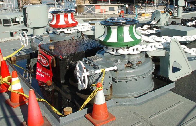
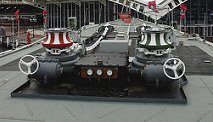
Just to be clear guys, it is not the V&W class but the Daring class I am talking of. These were the follow-on type to the Tribal and had a very similar hull form. This is a picy of the steam capstan arrangement on Vampire . The capstan stayed much the same even after the major upgrades in the late 60's; but, if you can find a picture of the pre-modernisation it might show a more-correct version.. Some of the surrounding structure, such as the cable ramps, drip/oil dam etc may be much diufferent but the steam winch is probably much the same - these were steam driven with the steam pressure dials ev ident in the central (black) box. cheers Pat
-
Again Greg, the Daring Class had a steam winch also; probably of the same type. I have photos of Vampire's capstan if that helps. Any of the 3D printed steam capstans of that period would work I think. cheers Pat
-
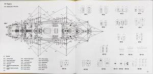
I can't state with definitive evidence, but the basic hull form of the Tribals look very similar to the later 'Daring' class, to which plan the Aussie Navy's Vampire, Vendetta and Voyager were constructed. It might be relatively safe to look at the plans of those ships (readily available) to establish the shape of a bow curve? cheers Pat
-
A lively discussion WRT to underwater fittings, the gudgeons, pintles, water intakes etc in my vessel (1855) were gunmetal.... Back on track though , the question related to upper deck equipment. In addition to the 'pretty work', such things as compass covers, especially the night covers, were usually brass and probably kept quite shiny - I know from experience that the 'morning watch' was brass work time, especially in the wheelhouse etc. Other items that sometimes attracted the polishing rag were the brass work on the Captain's gig (especially the brass in the rubbing strips), the ship's bells (forward and watchkeeping), brass ornamentation on such things as the bitts, companions and other upperdeck furniture. Some larger equipment in some 'period' ships also left the 'heads' and some fittings on such things as pumps etc brass simply as 'pretty work' - depended on the skipper (and if a warship, on the operational circumstances). As explained by John though, if it could be easily removed , it was stowed away in harbour if the public or other workers were embarking Just another pennies worth Pat
-
Thanks again for the info Dr. Per and Lieste; much appreciated. Dr. Per - appreciate that clarification which allowed me to move on using the Lees tabular data. For my project I found the 1st Class Brig data aligned quite closely with the screw-sloop I am researching and building. I applied the same formula to determine the appropriate ratio/proportion and applied it to my needs; as follows (the measured is as taken from the profile photograph of the ship I have - and conforms with the calculated proportions) Yard/Boom Lees Boom Length (Proportion of the Yard) Victoria Boom Length Victoria Given Diameter Lower Yard 55’ 56’ (Specified) Lower Boom 36’ 0.55 32’ 6” (Measured) 6½” (Measured) Topsail Yard 41’’ 43’ (Specified) Topsail Boom 27’ 6” 0.67 28’ 10” (Calculated) 5¾” (Calculated) Topgallant Yard 27” 25’ 6” (Specified) Topgallant Boom 20’ 6” 0.76 19’ 4” (Calculated) ⩳4” (Calculated) I must admit, due to the peculiarities of the spars in this vessel (similar as to what you appear to be finding with your project also) I have not looked closely at tabular data, especially in Kipping and Fincham. I may have to revise my thoughts on that; but, I am happy to say I have almost concluded my research in this aspect (spars) and well down the track with the rigging now. Thanks again for your info and pointer. cheers Pat
-
Deck planking methods
BANYAN replied to allanyed's topic in Building, Framing, Planking and plating a ships hull and deck
Hi Allan, I tend to use a wider central 'king' plank and allow for any 'crown' (I think that is what they are called - as in thicker) planks that are called for in way of guns and heavy equipment. I do work out a butt shift pattern but as you say, often between upperdeck furniture such as companions, hatches, etc, this pattern can go to 'custard'. Hence, most of my central planks (either side of the king) are measured to fit between the central upperdeck furniture and equipment where possible. I then start my butt shift working outboard from there to the crown planks, using the shift pattern you discussed on my thread related to 'shift pattern last year (maybe the year before?). Where possible, I try to make the crown planks fit the pattern but I am not 'governed by that. Druxy has identified 1700 as a general date for better organisation of the planks , so please note all my builds have been after that date. cheers Pat -
Thanks for the info Bob and Dr. Per. It just goes to show that no matter how often I checked, somehow I still missed that info in Lees. Can't figure how I did that, but do appreciate the pointer. Dr. Per, I am assuming the decimal values you provide are you calculations of the values provided in the tables (Lees)? As suggested, I am not too hung up on the exact length just need a 'rule' or indicated length to work with to get an idea of the diameters (for the ID of the irons). Many thanks Pat
-
Hi folks, back with another question for the more knowledgeable on these matters. I have read and searched far and wide to try and find guidance on the lengths of studdingsail booms. I have found guidance on the diameters (1" in every 5 feet of length) but except for one 'tid bit' provided by Jans Sajt (following) whom suggests they were about half of the length of the 'entire' yard I have not been able to find any guidance. These were not given in the ship's specifications either so I am hoping someone can point me in the correct direction. I have checked Lees, Lever, Harland, Underhill and Kipping. http://www.jans-sajt.se/contents/Navigation/Modelling/Patterns_Rigg_Stunsails.htm "The studding sail boom was half as long as the entire yard. When set, the yard would be extended to 1.5 of its own length. " I am not sure if the auther intended to use the word "entire' in this respect as that would make the boom as long as one side of the yard itself. This does not make sense to me - does he actually mean half of one side of the yard? Would appreciate any suggestions or pointers; many thanks Pat
-
YOUNG AMERICA 1853 by Bitao - FINISHED - 1:72
BANYAN replied to Bitao's topic in - Build logs for subjects built 1851 - 1900
Stunning work as usual mate; I am very impressed with the consistent high quality of your joinery - this is an exceptional build! I very much enjoy seeing your updates and especially the specialised tools you create. cheers Pat- 257 replies
-
- 3
-
-

-
- young america
- Finished
- (and 1 more)
-
If you call that crude I still feel ever so inadequate with my level of skills. I have had to remind myself on several occasions that I was looking at a model and not the real cabin. Exceptional work Michael. cheers Pat
-
YOUNG AMERICA 1853 by Bitao - FINISHED - 1:72
BANYAN replied to Bitao's topic in - Build logs for subjects built 1851 - 1900
It's always a pleasure to see updates to your build; very nice clean work as usual. cheers Pat- 257 replies
-
- 3
-
-
- young america
- Finished
- (and 1 more)
-
Michael, that is exceptional work; I'll try to find some room in that hole also - us mere mortals can just observe and stand in wonderment. cheers Pat
-
I understand the confusion and frustration you are feeling (undergoing a similar issue with researching my Victoria rigging from scratch ) Those translated booklets can sometimes add even further frustration. As to the book, it would all depend on whether you wish to build another model of this period and type - the Book "AOTS - The Armed Transport Bounty" has many plans including the usual full rigging plan on the inside of the cover; so if you do decide to get it, make sure the jacket is included. Here are two sample pictures from the web for it: cheers Pat
-
Dave, Amati (and many other older ship model manufacturer's/kits) plans are somewhat simplified and often just show the step/rigging of the lines being indicated for that step and not the others rigged in the same vicinity etc. If you do not have it, I would recommend a copy of the AOTS Bounty book which shows the rigging in much more detail. That said, you still need to look at all sections and illustrations (for standing, running etc) of these drawings to get the 'full' picture as the research behind the rigging is much deeper - in some instances may not even marry-up with the Amati plans. It is not easy as you are finding, especially for a first time builder of this style of ship. You are very much on track in trying to rig as much rigging and fittings to the spars before assembly, this certainly helps. There is no easy way around this unfortunately. It's your choice if you want to go the 'simplified path' as shown by Amati, especially if you are treating this as a leaning experience. However, you will need to look at both the standing and running rigging fittings on the different sheets/plans to get some feel. Often, as you are finding, the plan sheets differ in that a single or double block is shown in the same vicinity - depending on what rigging sheet you are looking at, these may be different blocks used for different purposes. From your description I think you have figured that the blocks shown are actually just one (each) of pairs of blocks rigged to the top over the trestletrees using a long strop with blocks seized into their ends (only showing the blocks on one side). The block with 3 holes being the upper block of a 'winding' tackle which is feasible (but unusual) but is dependent on its intended use (looks like it is used with the lifts in this instance). It is possible the other 2 hole blocks are for another purpose but rigged in the same position? Would need to follow the number identifiers to ascertain this (assuming the numbers on all sheets are to the same legend). cheers Pat
-
That's why we export it; no one here wants it cheers Pat
- 1,090 replies
-
- 8
-
-

-
- showcase models
- vendetta
- (and 2 more)
-
Steven, that is some nice detail that adds a lot of visual interest to the model. cheers Pat
- 740 replies
-
- 3
-
-
- Tudor
- restoration
- (and 4 more)