BANYAN
-
Posts
5,966 -
Joined
-
Last visited
Content Type
Profiles
Forums
Gallery
Events
Everything posted by BANYAN
-
 Hi Steven what CA were you using? Often I find the types used by many modellers just don't want to work that well with some media. I have had good results with Locktite versions. May be worth a try (can get them at Bunnings) cheers Pat
- 740 replies
-
- 2
-

-
- Tudor
- restoration
- (and 4 more)
-
So your found an awfully big ruler too...clever lad! Seriously though Steven, that deadeye is almost microscopic; and I thought I was working small stuff. Nice work. cheers Pat
- 740 replies
-
- 4
-
-
- Tudor
- restoration
- (and 4 more)
-
So you thought you would sneak another past me .... ha! caught you out. What an interesting build Greg, this will a nice one to follow along with. BTW what brand/type is that 'visor' in the second last photo of post #16 above cheers Pat
-
Divers Discover 2nd Century Military Ship off Egypt
BANYAN replied to Ian_Grant's topic in Nautical/Naval History
Thanks Grant, another great find. I wonder if/when someone will write a new book on the development/transition of building techniques based on this new evidence coming to light. With the many new finds in recent years, it would be great to see old texts updated to reflect the new material. (.... and no, I couldn't do it as I do not have the right skill set :)) I often wonder when I pick up an older reference book, whether some of the material needs an update. A simple check of te internet often is insufficient unless you know exactly where to look. Many of the sites where the info is stored requires paid subscription, and one can only afford to pay subscriptions a limited number of sites unfortunately. cheers Pat -
Hi Keith, purely from an 'ergonomic' point-of-view, getting in and out of the hatch, yet alone loading anything through it would have been problematic without removing the barrel of the windlass. With the barrel fitted, there would not have been much head/access room above it for about half the hatch opening as best I can see? Then as pointed out, the mechanics of the windlass are seriously affected by placing barrel axle higher up (leverage alone as the sailors were not very tall mostly). Filling the hatch is neither here-nor-there I think, as people did not have to step on it to work the windlass. The barrel could be rotated with longer staves a little further outboard from the centreline. Hope this clarifies, from my perspective at least, Keith? cheers Pat
-
You select some very fascinating subjects to model Steven - missed the start, but it seems you have made a very good start. Any room left in the front row? cheers Pat
-
Tom, as I offered in my first post, I think it is higher than usual due to its placement so close to the hatch. Once the windlass barrel is added etc, some additional clearance may have needed to allow the hatch to be used effectively? A bit of a long draw of the 'bow string' but... cheers Pat
-
Hi Brian; wow! looks great. If it is only the edges of the planking in the cutaway area, I say go for it. As you say, it will highlight the area and differentiate between the planking and framing (which look in natural timber). cheers Pat
-
The suite of sails look great; good effort on perservering with the broken yards. If you are staying with the glue on method Steven, perhaps put some clear 'contact' over the template which will stop the glue sticking to the paper? cheers Pat
- 740 replies
-
- 3
-
-
- Tudor
- restoration
- (and 4 more)
-
Initial thought is they look like the standards for a windlass? A little high though but that could be due to the close proximity of the hatch under them. cheers Pat
-
Thanks Steven - awfully big matches you have (are they the BBQ long ones?) Seriously though, you are making great progress and those sails look great. cheers Pat
- 740 replies
-
- 1
-
-
- Tudor
- restoration
- (and 4 more)
-
Very nice joinery Dave; especially on those complicated joints. Are you using experience (eye balling) the cuts or using a jig? cheers Pat
-
Nice work Steven. You should add a ruler to one of the shots to remind us just how small this work is. cheers Pat
- 740 replies
-
- 5
-
-
- Tudor
- restoration
- (and 4 more)
-
Some really nice 'bodging' there Greg. The added detail will look great when added and certainly show off the differences. cheers Pat
-
I'm late to the party again Greg. A very nice build of an interesting subject matter. How have you found working with resin? Appears you have had no probs at all. cheers Pat
- 53 replies
-
- 5
-
-
- photo etch
- resin
- (and 3 more)
-
Nice recovery and fix Steven, these frustrations are sometime so close to making you want to ..... cheers Pat
- 740 replies
-
- 2
-
-
- Tudor
- restoration
- (and 4 more)
-
Hi Rob, nice work on the detail; looks very effective. We used threads (soaked in PVA) for the scroll work; I'll be interested in seeing how you did it? cheers Pat
- 3,560 replies
-
- 2
-
-
- clipper
- hull model
- (and 2 more)
-
Hi George, I would have to agree with your deduction/assessment that a sliding hatch better conforms with the detail shown in the Admiralty Drawing. I can understand your apprehension, but I think these sliding hatches were used extensively and were constructed in such a way they did not jamb when operated. Also, while occupying additional deck space (horizontal plane), this may have been necessary to minimise height (vertical plane). This would be particularly important for operating the capstan etc where the bars needed to clear any obstructions; the flat (sliding) cover allows crew to walk on them. Not sure what equipment was in this area based on the cropped plans you show, but may need further consideration cheers Pat
-
I have found that once blackened and rinsed, immediately 'polishing' the parts with a soft cloth/paper towel (to remove the powdery residue) works wonders and I then have no issues with 'scale'. This leaves that nice iron grey finish Tim refers to. I have no issues with polishing even very fine parts by simply rolling/rubbing them in the cloth/paper. Allan, I prefer a nice juicy steak - I'll leave the snails for you cheers Pat
-
The completed (repaired) model will look great with her new suite of sails Steven, you are managing to add some significant detail while remaining true to your very early efforts. cheers Pat
- 740 replies
-
- 6
-
-
- Tudor
- restoration
- (and 4 more)
-
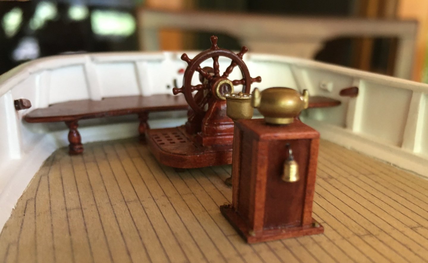
Hi Allan, just to be sure, the brass belfry (and bell) in the earlier photo are actually brass - the FW tank cock and breather pipe are painted. The following is the brass compass cover (dry fitted) on the binnacle and the EOT - this is the dulled look I was talking about. You can compare the colour against the watch bell which has been turned from brass. cheers Pat
-
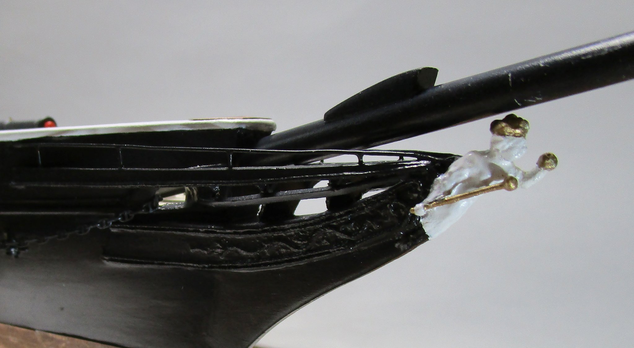
Hi Allan, not the Mr. Metal/Colour brand as of yet I think - will need to check. I have used a gold paint for the gilding on the figurehead. cheers Pat

-
Allan, the paints are both from Gunzo (Japanese): 1. The more silvery (with flake) is Mr. Metal GX201 - Metal Black 2. The canon is don with Mr. Color MC214 - Dark Iron If you intend using the former also, make sure to shake the bottle really well before decanting off a little for diluting. Both paints dry very rapidly so leaving the cap off will thicken them really quickly. The brass paint I use is also from the Mr. Color, I haven't got the code but there is only 1. I like it as it softens to a dirty brass (aged) look and can be hand painted (all Mr. Colour paint can be brushed or airbrushed, but the latter requires a little dilution with Mr. Paint thinner (get the right one for the right paint). I like to use Tamaya (spray can) undercoat. Hope this helps you? cheers Pat