BANYAN
-
Posts
5,965 -
Joined
-
Last visited
Content Type
Profiles
Forums
Gallery
Events
Everything posted by BANYAN
-
 Ditto Druxey's comment; those sketches are just as impressive as you building skills. cheers Pat
 -
Impressive work Mark. the second from last pic of your build is so very lifelike. cheers Pat
-
74-Gun Ship Gun Deck by Jeronimo - FINISHED
BANYAN replied to Jeronimo's topic in - Build logs for subjects built 1801 - 1850
Stunning Cross section model Karl. I enjoyed looking through your build. cheers Pat -
Some nice resin and PE parts there Greg. WRT screw, while a much nice part I note it is 3 vice 4 bladed - which was correct? cheers Pat
-
Nice find Joe, I would be very interested in any feedback on this product. cheers Pat
-
Keith there is a point (scale/size) where it is just not possible. The block above looks good mate, but might I suggest that unless it is just a temporary fit, the bottom line should be coming from the top (as you look at it) hole in the block such that the fall is working over the sheave? At your scale the work in your 'creation' is nice and clean. cheers Pat
-
HMCSS Victoria 1855 by BANYAN - 1:72
BANYAN replied to BANYAN's topic in - Build logs for subjects built 1851 - 1900
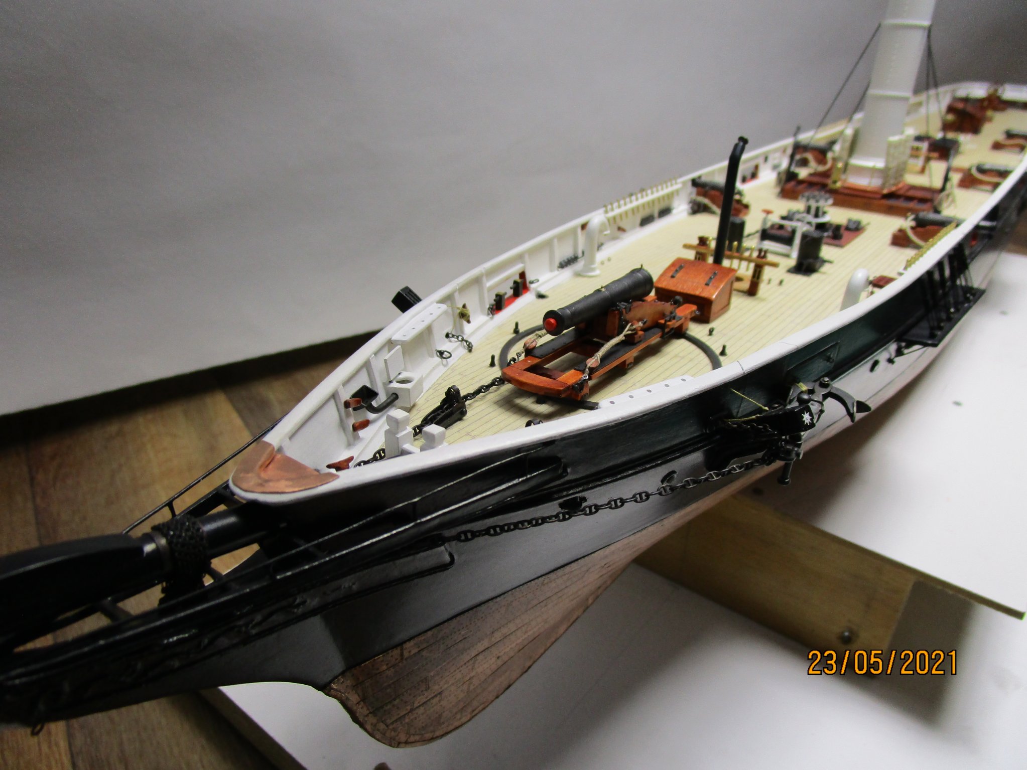
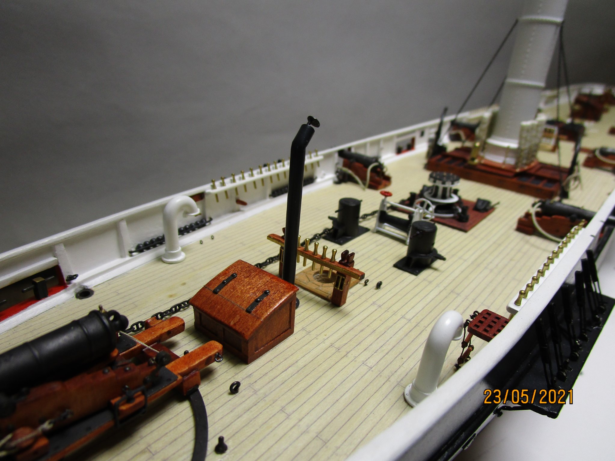
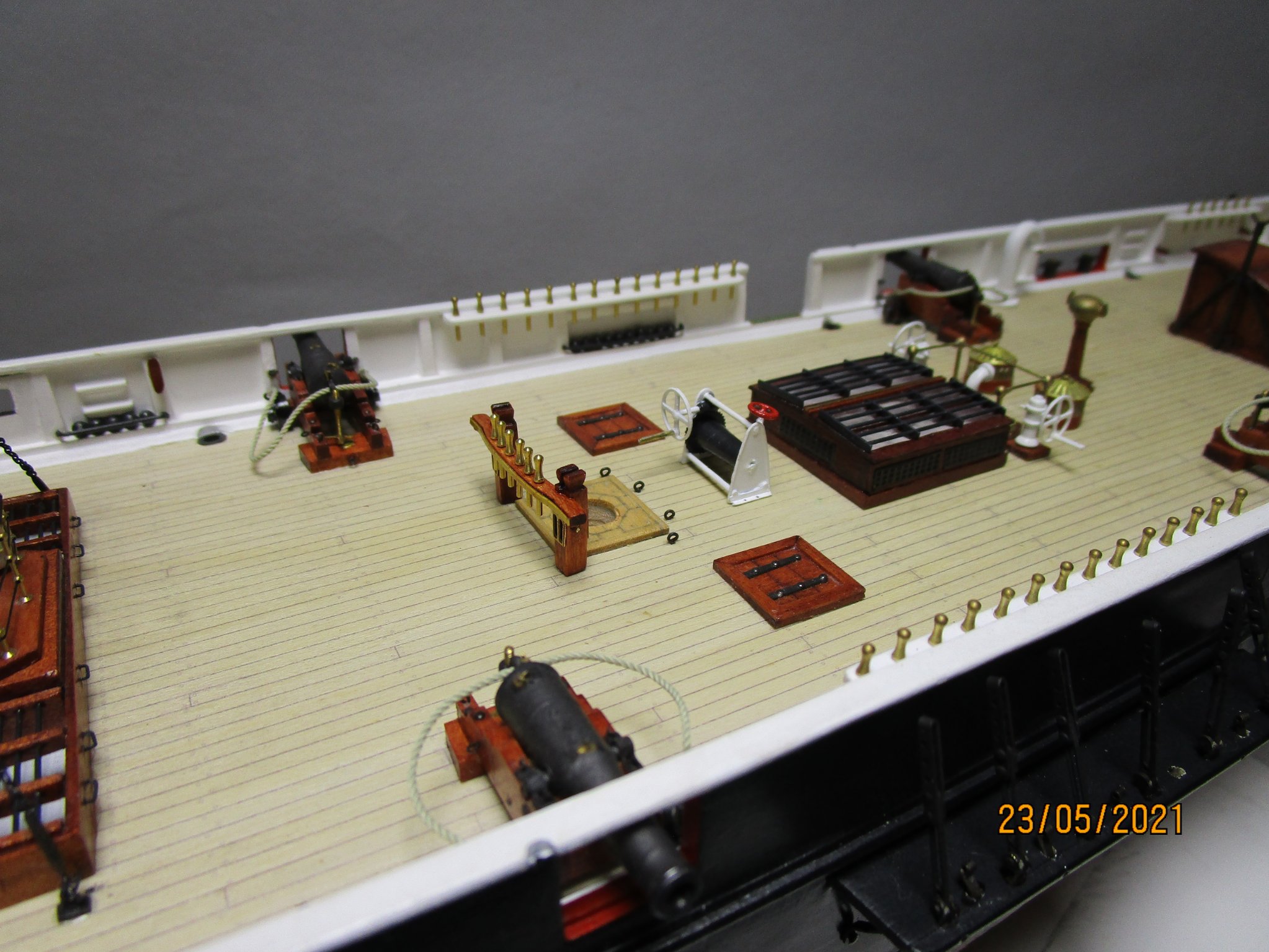
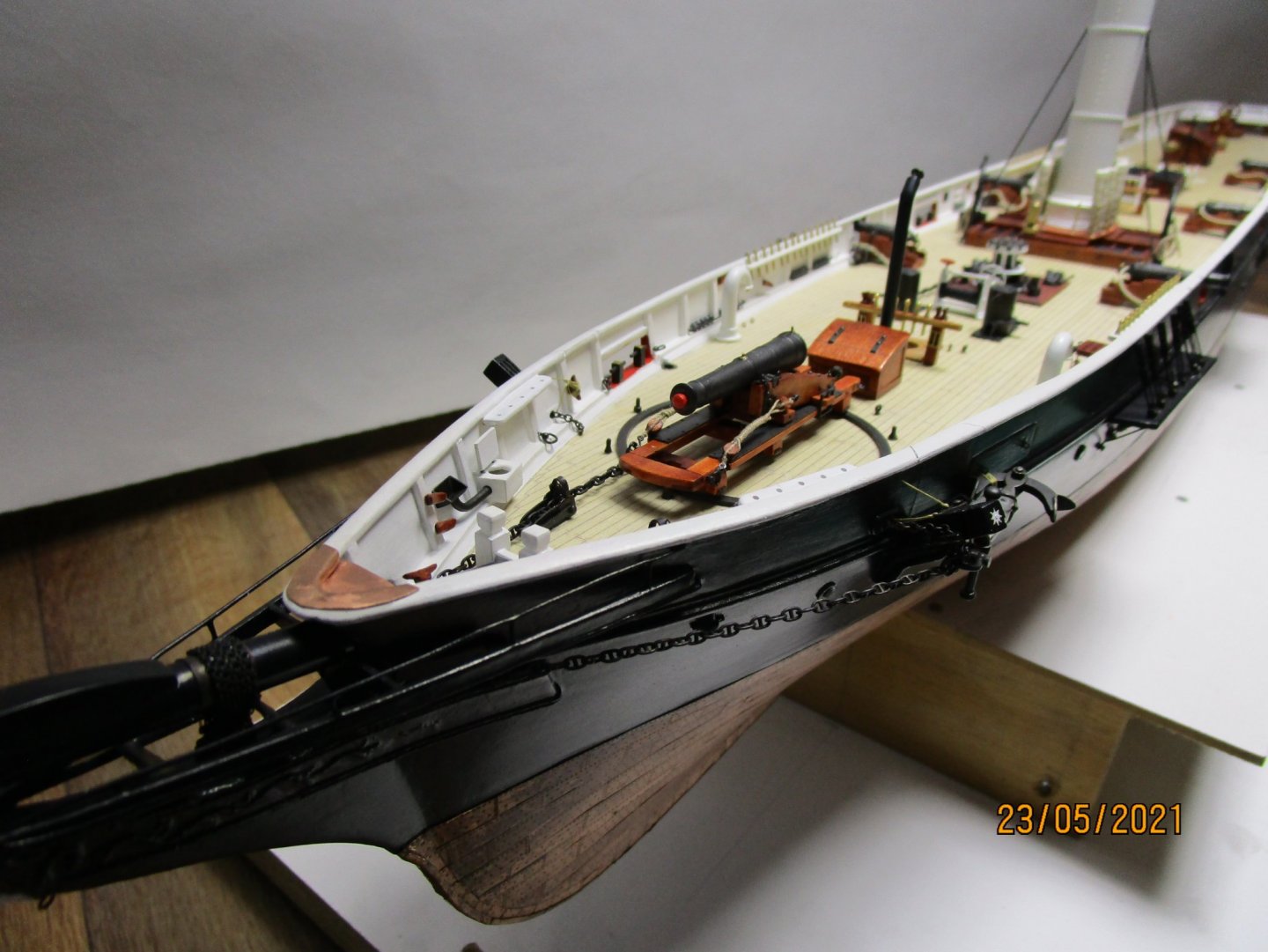
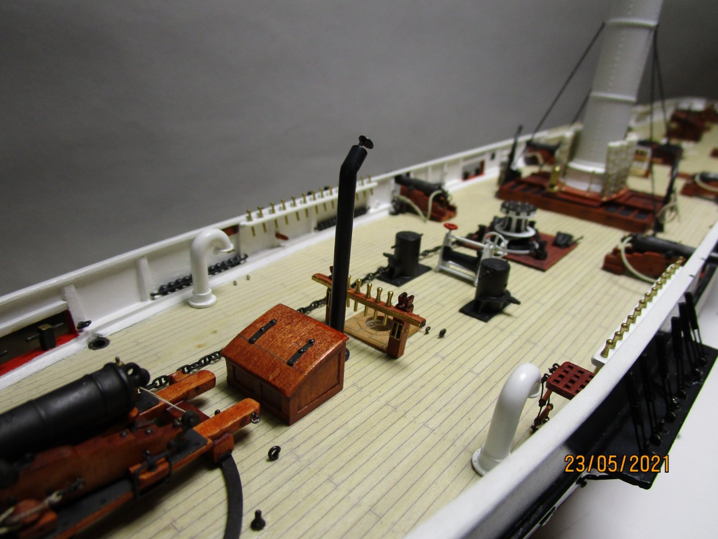
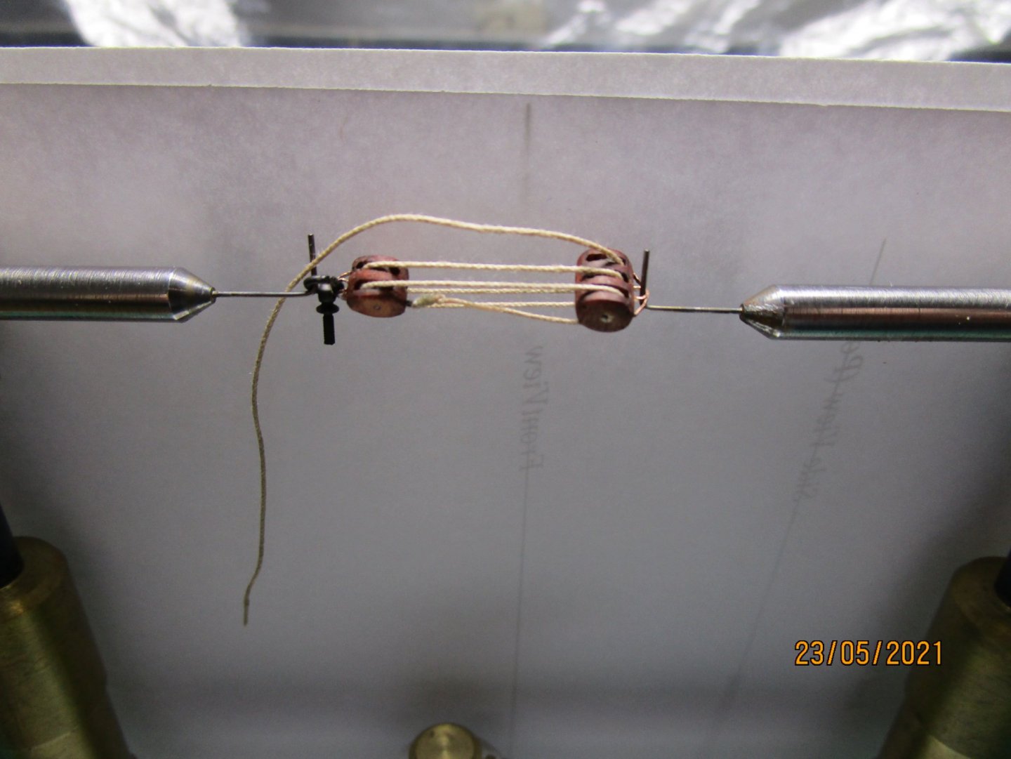
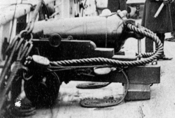
Ok folks, another small update. This shows current progress of what I have actually fitted but there are a lot of items already made up (such as davits) that are yet to be added. The new updates show the bitts and fore pinrails fitted (but belaying pins still to be added) and the 'charlie noble'. I am in the process of designing the gallows, which incorporated a 100 gallon freshwater tank and the belfry, at the moment. This will be fitted just abaft the foremast. In the meantime I am also working on the bowsprit which can also be seen in the first photograph. The gammoning (chain) with its scotchman (iron sheet nailed to the top of the bowsprit) has been added. I am also working on the stay (fore, main and mizen) tackles which I am pre-fitting and will add the stays later as there won't be much room to fit the forestay tackles in particular. As you can see these were made up from the more modern style internally iron bound blocks (sourced from Chuck - Syren). The lower block is fitted to the deck eyebolt with a ring. The eyebolts have a thread applied so they will grip the wood better when glued in place. I have based the tackle on some detail extracted from a photograph taken in 1865 which provided confirmation of the type of block and allowed me to calculate the size of the block (13") - Chuck's block equates to just over 12.5" at 1:72 so is pretty close. I have still to clean the stain from the iron eyes etc - this is just a proof/trial of how to make them up. From the eyebolt to the eye of the treble block is 22mm. For those intrigued, I am using one of Michael Mott's excellent third hands, fitted with hook arms kindly made for me by Eberhard Falck. The block shells are 4.5mm long. cheers Pat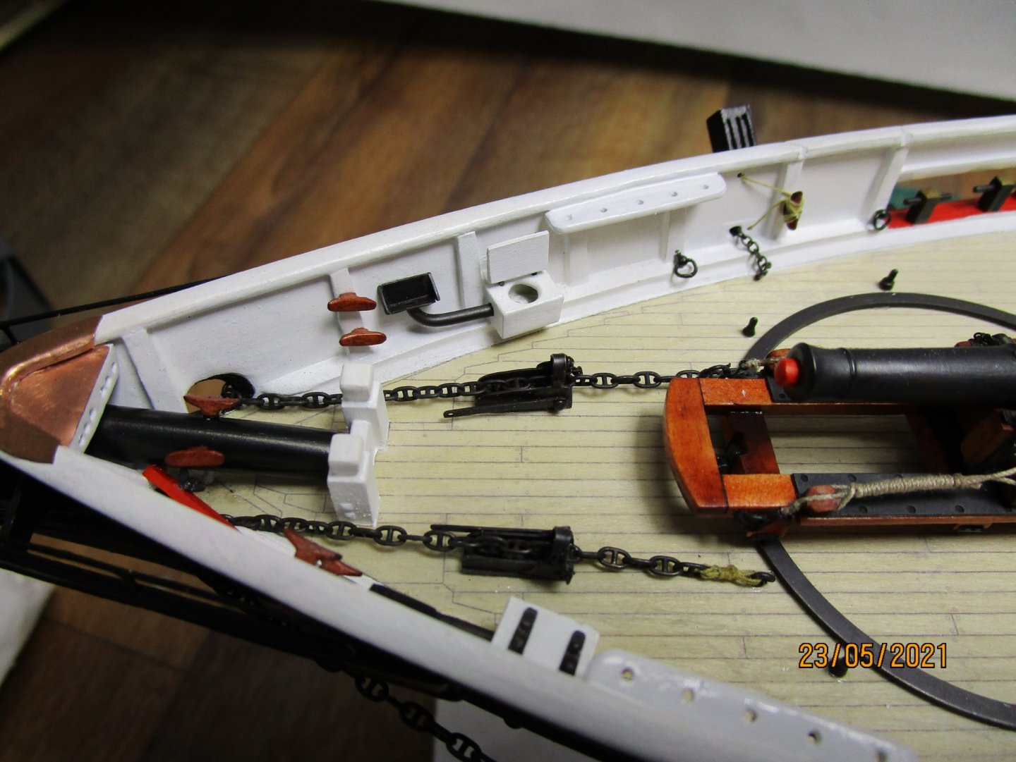

- 1,021 replies
-
- 17
-

-

-
- gun dispatch vessel
- victoria
- (and 2 more)
-
Keith, no easy answer I am afraid. These days with modern steel shackles, one of the more important factors is 'breaking strain' / how tensile is the pin etc. To be honest I have not worried and simply used thin wire to join the two item as above. Just enough detail to suggest a shackle. cheers Pat
-
Oh come on Keith - shackles should be easy Just kidding mate! At these scales I use thin wire as a loop to join the hook (or other item) to the block/eyebolt and twist the two ends together, bend the twisted wire to 90 degrees to the loop, then snip off leaving a short projection to simulate the projection of the pin. As to hooks, there are some very small photo etch versions around if you want to use them. cheers Pat
-
YOUNG AMERICA 1853 by Bitao - FINISHED - 1:72
BANYAN replied to Bitao's topic in - Build logs for subjects built 1851 - 1900
Yankee Clipper - did you get the CDs? I seem to recall all the plans were also provided in digital format - may be mistaken though. If provided, you should be able to get them printed fairly cheaply from the CD? cheers Pat- 257 replies
-
- 2
-
-
- young america
- Finished
- (and 1 more)
-
The many small jobs needed before you can even start rigging is incredible. The blocks alone take significant time as you have found; the effort has paid off though, they look good. Now for stropping them, not to mention the hooks, shackles, etc - Sorry cheers Pat
-
Some really stunning detail there Druxey, a credit to your skills. cheers Pat
- 433 replies
-
- 4
-
-
- open boat
- small boat
- (and 1 more)
-
Nice job Dave. I cheated with my multi-faceted waterway and made each level with its unique bevel separately. Looks like you got a nice clean shape with your method. cheers Pat
-
That SS looks good, yep a little cool but as your hull is 'pale' it suits/compliments I think. Tool envy indeed; they are some seriously nice hand tools. cheers Pat
-
Condolences on your loss Brian. The work on your build continues with its excellent quality - impressive for a first scratch build mate. Funny how those little 'errors' come back to bite; especially when you think you had it nailed. I have experienced a few of those. cheers Pat
-
YOUNG AMERICA 1853 by Bitao - FINISHED - 1:72
BANYAN replied to Bitao's topic in - Build logs for subjects built 1851 - 1900
Simply stunning work all round. cheers Pat- 257 replies
-
- 3
-
-
-
- young america
- Finished
- (and 1 more)
-
Just came across your build Mark, your half model is looking great. I am into bigger vessels, but the grace and beauty of these 'flyers' catch my imagination. Following along with interest. cheers Pat
-
Druxey, I have experienced the same issue with the disk sander and also received a replacement switch from Jim and installed it. However, I am seriously contemplating changing the switch of all my tools to a new arrangement that I have set up for my lathe and 10" table saw. That is, bypassing the toggle switch and connecting to power via an 'emergency stop on/off switch that I place near the saw but is easier to access and easier to stop the saw in an emergency. This of course means I will be restricted to moving the saw on the bench within the length of the power cord/cable I build in - but this is not an issue for me. cheers Pat
- 433 replies
-
- 7
-
-
- open boat
- small boat
- (and 1 more)
-
Thanks Druxey, that explains why it is safe and very convenient to add that detail now. cheers Pat
- 433 replies
-
- 3
-
-
- open boat
- small boat
- (and 1 more)
-
Looking great Druxey, are you clear coating or painting the interior? If painting how do you protect the metal work if it not easily accessible? cheers Pat
- 433 replies
-
- 4
-
-
- open boat
- small boat
- (and 1 more)
-
YOUNG AMERICA 1853 by Bitao - FINISHED - 1:72
BANYAN replied to Bitao's topic in - Build logs for subjects built 1851 - 1900
Exemplary work - your skills shine yet again. cheers Pat- 257 replies
-
- 3
-
-
-
- young america
- Finished
- (and 1 more)
-
Keith, I am researching the studdingsail booms for Victoria at the moment. For ships of the era we are both interested in/building, the various authors all suggest that it was usual to have the swing booms fitted to the fore-end, and parallel with the fore-channel (not common to carry a lower studdingsail on the main). A crane (chesstree with a hinged metal bracket) was fitted on the hull near the end of the boom such that when swung in/aft, it securely held the boom parallel with, and out the same distance from the hull as, the channel. In Victoria, this is evident in the profile photo I have of her which shows a gooseneck fitted on her inner boom end. The cranked gooseneck seated in a lug fitted on the fore part of the fore channel. Even if Tennessee did not carry studdingsails, she probably had the boom fitted as a boat boom anyway? She then would have a fore and after guy, topping lift and associated lizard, and rope ladders, painters etc on the boom (only when in use). Hope this is of some value? cheers Pat