BANYAN
-
Posts
5,937 -
Joined
-
Last visited
Content Type
Profiles
Forums
Gallery
Events
Everything posted by BANYAN
-
 Hi Kev, if I am following correctly, especially Q3, I am not sure I fully grasp the issue. But then again it is easy to confuse me When planking, each plank should be 'spiled'. There are some good article by very experienced builders in the Knowledge Base. A common practice by modellers, is to divide the planking area into bands then try to make each plank within a band to the same dimensions, such that when fitted they completely fill the band space. If correctly spiled, similar dimensioned planks could be a starting point, but each individual plank should be spiled (adjusted) to fit correctly and maintain the natural 'lay' of the plank against the frame or bulkhead. If spiled this would then eliminate any accumulation of rise or fall surely? The articles mentioned above cover spiling etc quite well and there are several methods of applying it. The bevelling is simply to ensure the plank edges mate correctly. In the articles have a read of the spiling rules and the use of tick marks etc. It may help explain. cheers Pat
 -
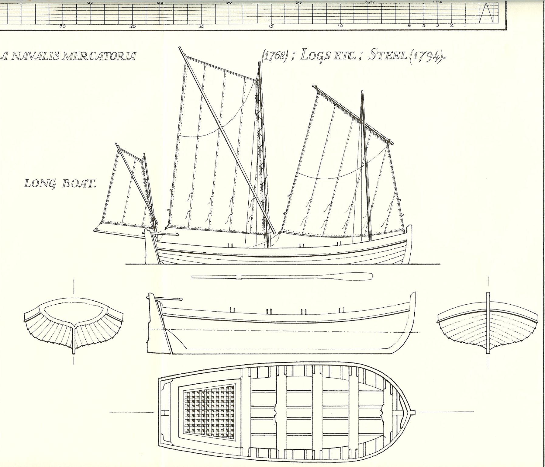
HMS Endeavour's Longboat Rigging
BANYAN replied to Dougal Mack's topic in Masting, rigging and sails
Hi Dougal, there are several answers to your question unfortunately. Like many rigging subjects it is open to some conjecture. For instance, Karl Marquardt in his AOTS Capt. Cook's Endeavour shows a couple of way sto rig the long boat, one using a sliding batten or something. Unfortunately I have loaned out my copy at the moment so cannot provide the detail. Then Ray Parkin in his HM Bark Endeavour, not only shows a different boat design, but slightly different rigging again. It is a while since I looked at these, but one author argued for a long narrow design whereas, but due to the space to stow the boats, the other author argued that a shorter wider design was probably used. Due to copyright, we are somewhat restricted in posting too much from these books. I have however, attached one of Parkin's drawings. I would highly recommend getting Marquardt's AOTS, the other (Parkin) is a tad too expensive for what you want. That said, I think Parkin based his rigging on Steele's Rigging Rules (PDFs free on line) so using that as a reference may help you? The NMM, has some plans for long boats but not much on rigging (that I found), but even better plans are in the Danish Museum Online Library - may be worth a look. This is just one link into one of several collections - may not be in this one so you will need to explore (and also turn on your browser translator) cheers Pat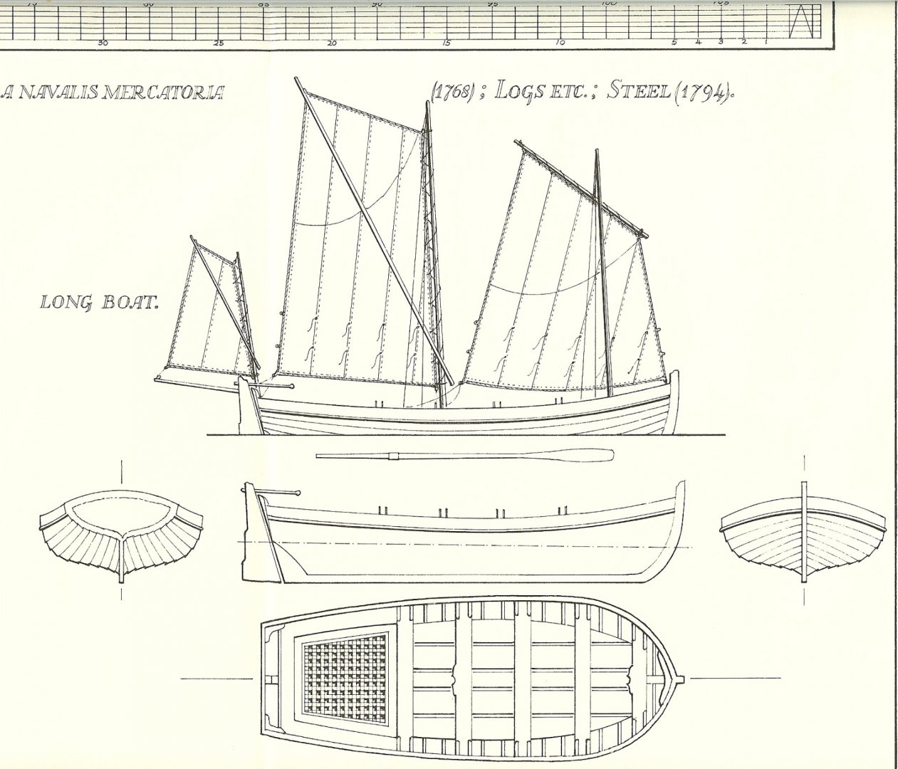
-
I love seeing how you develop solutions to create your ironwork Keith; it is as great a pleasure to see that process (and the jigs) as it is to see the quality of the finished products. cheers Pat
-
Pierre, the Jylland is a museum ship (if we are talking about the same vessel). You could try contacting them. Also, if I recall correctly someone recently posted about the plans for this ship being available in the Danish online digital collection - not sure if the plans include a rigging or belaying plan though. Hopefully, someone will recall that post and relink it for you. I am currently working on a steam-screw vessel of the same period. What I am finding in researching her, in particular the rigging, is that more so than in earlier times, the rigging differed significantly between ships and only conforming with the broad rigging plans for steam vessels of this period. Good luck Pat
-
Man that is some quality joinery Michael, great to see you back. I had to look twice at one of your photos to see if it was not the real thing - now that is mastery of the trade! cheers Pat
-
Topsail schooner sail plans and rigging
BANYAN replied to Dr PR's topic in Masting, rigging and sails
George, further to Allan's excellent overview, for mid-19th century Kipping and Fincham (both 1855) also offer advice, plus variations for those fitted in steam vessels. Further reference can be made to Underhill for later types fitted in clippers and steel masted ships. As Allan says, depends on the period, type of vessel and even whether a Service or Mercantile vessel. cheers Pat -
Thanks very much Arina; sounds like a very interesting gentleman. cheers Pat
- 3,560 replies
-
- 1
-

-
- clipper
- hull model
- (and 2 more)
-
What a great opportunity and meaningful day for you Rob; glad you enjoyed it. I am sure we'll see some changes to your hull shape emerging in the near future? By chance, did he happen to mention who the shipwright down my way was? cheers Pat
- 3,560 replies
-
- 2
-
-
- clipper
- hull model
- (and 2 more)
-
What do we know about the origins of the lifebuoy?
BANYAN replied to Sperry's topic in Nautical/Naval History
Hi Diver, ah the 'joys' of the bosun's lash. We had similar 'no no's' in the RAN. Then the 'divers' got really upset with 'goggles' or 'flippers' cheers Pat -
Another Rigging Clarification Needed - Lifts
BANYAN replied to BANYAN's topic in Masting, rigging and sails
Couldn't agree more John, that is why it has thrown me. Not only associating tackles, but also the lift itself has a thimble and hook. lees says a soft eye over the yardarm stop, but Underhill says hard eye shackled to yardarm band lug. My current interpretation being that the lifts were set-up as standing lifts that were hooked, rather than shackled, at the yard arm and once hove taut, the working end was seized to a topmast shroud leg (within working reach of the top). POSSIBLITY: The lift was set-up with the hook to allow it to also be used as a sort of (mast) pendant for working/setting-up lower rigging? The tackle was provided to assist the tye/halliard when lifting/lowering the yard as required (only tailed on as required). This sort of fits with Underhill whom says the weight of the yardarms was carried by the lifts, and a tackle used when hoisting them into place. Only sort of arrangement I can think of that might work that utilised the fittings listed in the Rigging Warrant. cheers, and thanks for your continued interest/assistance. Pat -
Very nice result Keith. Love that hand drill set-up - is it a sensitive drill type also" That would allow you plenty of control ofver some of thos drilling operations. cheers Pat
-
Photoetch brass black problems
BANYAN replied to Seems ok to me's topic in Metal Work, Soldering and Metal Fittings
I have done that many times. I used the scratch pens to do that, but a thorough clean is needed. I have tried the Sparex, but found it did not work so well for me (could be technique etc). I have used a Ultrasonic cleaner but it is not necessary. cheers, and good luck. Pat -
Another Rigging Clarification Needed - Lifts
BANYAN replied to BANYAN's topic in Masting, rigging and sails
Thanks John, that accords with Underhill also - all upper yards lifts were standing lifts. I was thrown with the association of the tackles (tackle and runner). I am now wondering if the tackle was for hooking to the lifts to balance the lord/weight of the yard whenit was being struck/raised into position (I think Harland reflects) this? Last question then, based on the above assumption, I think the thimble and hook would then go on the running end, and a soft eye over the yard arm. Although, as you suggest it may have been shackled (hooked?) cheers Pat -
Welcome aboard Arina, we look forward to the results of the forthcoming conversations. regards from Downunder Pat
- 3,560 replies
-
- 4
-
-
- clipper
- hull model
- (and 2 more)
-
Another Rigging Clarification Needed - Lifts
BANYAN replied to BANYAN's topic in Masting, rigging and sails
Bump - any ideas anyone? -
Very nicely constructed hull Pavel, look forward to your log. Another warm welcome. cheers Pat
-
Rob, you lucky devil - I wish I could run into a shipwright or expert like that re Victoria, even if just for the conversation (I understanding you are talking with Michael but even so, has had the benefit of the other discussions and knowledge to pass on) - envious! Seriously though, that is great news for you. cheers Pat
- 3,560 replies
-
- 2
-
-
- clipper
- hull model
- (and 2 more)
-
Photoetch brass black problems
BANYAN replied to Seems ok to me's topic in Metal Work, Soldering and Metal Fittings
Hi [nickname?] I have been doing both methods of finishing PE you mention for some time, and this response reflects my experiences only - may be alternate answers forthcoming The brass stock used with PE is sometimes covered with a protective coating, or has some residual chemical coating, that needs to be removed. I find that cleaning with a fibre scratch pen (like a propelling lead pen) helps greatly, especially if the PE is to be soldered also. If painting, I also found that using a metal etch solution (such as those from Mr. Metal) helps the paint adhere. Even if well cleaned and undercoated with a good quality primer, without such a metal etchant, I also experienced the same scratching issues. If blackening, here cleaning is very important. I also scratch clean with the fibre pen for this process to ensure I remove the coating. Your cleaning is OK I think, but the main issue I see here is the strength of the blackening solution you are using. I have found it is better to use a diluted solution. I start with a 50/50 demineralised water/birchwood casey blackening solution; however, with some metals an even weaker solution creating a 'slow baked' patina gives a better result.. I usually give the part about 5 minutes in the first dip then check progress. Even with the best cleaning sometimes, parts of the PE fail to take the patina initially. If I see areas not blackening, while still wearing rubber gloves - nitro type, not the powdered ones) I give the affected areas another clean with the scratch pen. You have to be careful with PE as you have probably found already, some parts are very delicate. It is then put into the blackening solution, then checked again after a few minutes. Sometimes I have had to do this three times. The results I get are a nice grey iron like patina initially. The longer, and more often you put the parts into the diluted solution provides a deeper colour. Between baths, once I have a full coverage, I wipe/polish with a paper towel to see what the depth of colour is. Once happy with the colour, rinse well under flowing fresh water and polish dry. I hope this works for you. Happy modelling. Pat -
Another Rigging Clarification Needed - Lifts
BANYAN replied to BANYAN's topic in Masting, rigging and sails
Ok, now that the lower lifts are resolved; here is another one that bamboozles me a little. - The Topsail Yard Lifts. While discussing this, please note this yard was fitted with an iron parrel on Lt. Green's patent as shown by Underhill. The RW lists single lifts again but the lift itself having no associated block but does have a thimble and a common hook. I am trying to figure out which end the hook would be. Lees says a soft eye was formed outboard and placed over the yardarm (lower yard had an iron band and I would think this yard would also?). This would put the thimble with hook on the inboard/running part. There is a tackle with runner also listed. the tackle is formed with two 6" single blocks, and the whip (if the runner, if that is what it is) has a thimble and another 6" single block. I am basing this on the convention used in the RW that has the tackle immediately following the line with which it is associated, and the 'tackles' are grouped/bracketed. This seems an extraordinary amount of 'power/mechanical advantage' for a lighter yard, which would be restricted in canting by the iron parrel? This yard is also hoisted and lowered with the chain tye to a wirerope halliard fitted to a winch, so I doubt this amount of power would be need to assist in hoisting the yard. Lees, Underhill, Harland and others I have looked at, do not appear to discuss any arrangement like this (unless I have missed something). Surely, for this to work (cant the yard) the parrel would have to be released I think. How often was the topsail canted? Am I missing something very obvious? Underhill mainly talks of standing lifts in this era where the inboard end was belayed or seized to the middle shroud of the gang (des not state where); but, then why associate tackles if a standing lift. And, why such a powerful tackle for a lighter yard? I understand some power would be required as this yard does not have a central pivot point. Any pointers, suggestions or comments most welcomed. cheers Pat
-
Another Rigging Clarification Needed - Lifts
BANYAN replied to BANYAN's topic in Masting, rigging and sails
Thanks guys, even though that was the only workable solution I could see that incorporated the listed fittings in the Rigging Warrant, I was concerned with the 'weight' . Much appreciate the reassurance, this would have worked. cheers Pat -
Hi Bruma, Underhill (Masting and Rigging the Clipper Ship and Ocean Carrier), page 142, writes that the downhauls were led through lizards seized to the hanks along the luff of the sail. This then would have them fitted on the hanks rather than running on the stay; the hanks then ran up and down the stay. He illustrates this in figure 22 of the book (sorry due to copyright etc, can't reproduce here). cheers Pat
-
Hi again folks, another conundrum I am trying to resolve. I would greatly appreciate any thoughts on the following. The Rigging Warrant (RW) for HMCSS Victoria lists lifts single associated with a 7" double block and a clip hook with each, lift tackles associated with a 7" single block each, and a Jigger. Lees page, 69 explains the jigger, which was removed after the yard had been hoisted into place, so it is not relevant to this discussion. Of note the RW notes specifically that the lifts are 'single' which ties in with Underhill's description of their rigging. Underhill, page 157, informs that lower yard lifts were always rigged as running rigging and provides some guidance that largely aligns with the RW listing; except using single blocks with the lift, BUT, more importantly utilising a purchase. Based solely on using the listed rigging fitting associated with each lift and tackle ONLY, the arrangement probably used in Victoria, will have had the 7” double block shackled forward on the sides of the upper cap. The purpose of the outer sheave has not been determined but may have been used to lead the associated top rope when fitted. The single lift will have been made up with the outer end, or standing part turned on a thimble, and spliced back into itself. This end was then shackled to the upper lugs on the yardarm band. The lift was then led up through (fore-to-aft) the inner sheave of the 7” double block fitted on the respective side, forward on the lower mast cap. The running end of the lift was also formed in a hard eye with the thimble rove through the eye of the clip hook. The running part of the lift was led down through the lubber’s hole in the lower top and hooked (and moused) to the running block of a whip. To allow sufficient working length, the end would have terminated just below the lubber’s hole with the yards set horizontal. A hard eye was sliced into the standing end of the whip fall which was shackled to an eyebolt in the deck abreast the mast near the partners. The fall was rove through the 7” single block which was hooked to the lift, forming a whip. The working part of the fall was then led down, possibly through a bullseye fairlead, or belayed directly to a pin. The use of a whip for the lower yard lift seems rather unusual but is the only arrangement I can think of that uses only a single block. Does this make sense at all? It seems to me that such a heavy yard will have required a purchase to gain the necessary 'power' to cant the yard arms? cheers Pat