HOLIDAY DONATION DRIVE - SUPPORT MSW - DO YOUR PART TO KEEP THIS GREAT FORUM GOING! (Only 53 donations so far out of 49,000 members - C'mon guys!)
×


BANYAN
-
Posts
5,941 -
Joined
-
Last visited
Content Type
Profiles
Forums
Gallery
Events
Everything posted by BANYAN
-
 That should work well Steven. Now to set up the production line For those whom may have been concerned of my offer to Steven in these troubling times, I am self-isolating as best as we can and make such offers very judiciously (only to people whom we know well enough to feel comfortable will have taken every precaution and would not travel if there is even the slightest hint of being unwell). cheers Pat
 -
Man-o-man you achieve some very nice detail into your metalwork. I am still trying to figure how you did those flanges on the elbow (a bit of file work I am assuming?) Works of art Keith! cheers Pat
-
Making extremely tiny fittings
BANYAN replied to BETAQDAVE's topic in Metal Work, Soldering and Metal Fittings
Thanks for sharing this Kurt, you have just given me the solution for making 'cheek blocks' for the yards and bowsprit of my model A small modification, drill a hole for the sheaves and not open the top, a bit of rounding with a file and hey presto. cheers Pat -
Steven, the offer is still good to use the scroll saw for cutting/ rough shaping the carving blocks if you are game to travel? cheers Pat
-
Making Rope Coils with a Jig by Peta_V
BANYAN replied to ccoyle's topic in Masting, rigging and sails
Thanks for sharing Peta, a modified (and better) version of a method I have been using. cheers Pat -
Hi Keith, it is possible that the rounds were passed up to the upper deck through a hatch/trunk/hoist from the shell room. It would make sense then that only a single greasing station would be required as the crew would grab the round from the hoist, grease it and pass it to the required gun station. Could the device be a combined hoist/greasing station? Not trying to complicate the matter, just a suggestion. cheers Pat
-
You must feed those 'galley slaves' / Workers well - nice production run (and fast) At this rate you will be finished the ship before you know it; the crew may be another matter? cheers Pat
-
HMCSS Victoria 1855 by BANYAN - 1:72
BANYAN replied to BANYAN's topic in - Build logs for subjects built 1851 - 1900
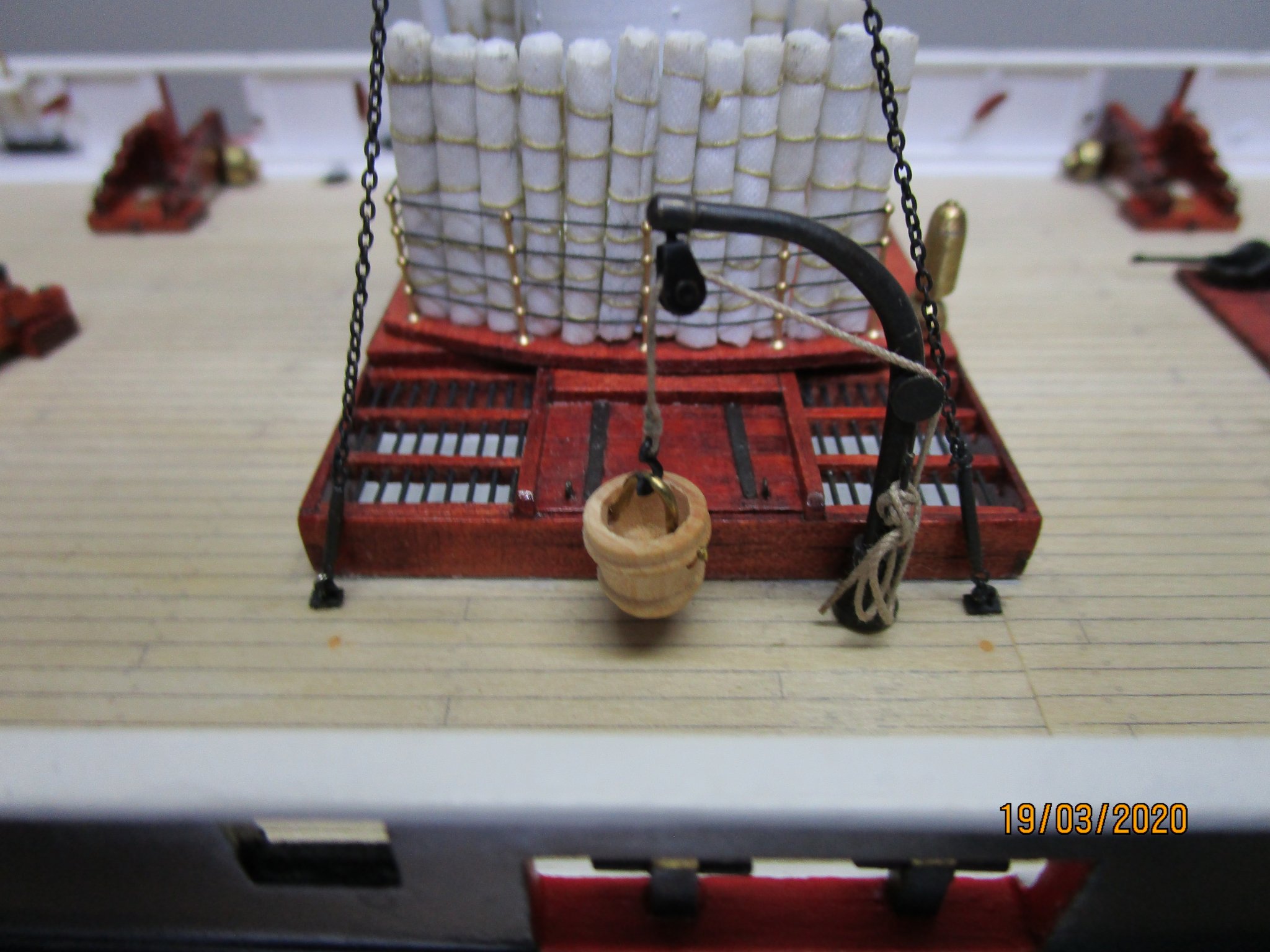
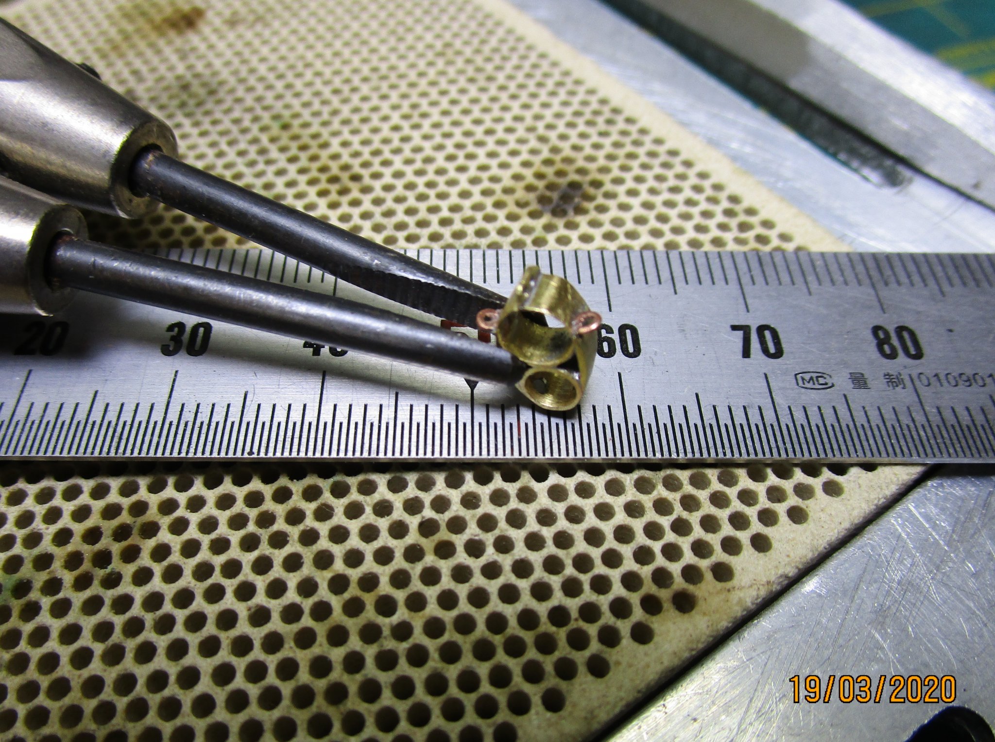
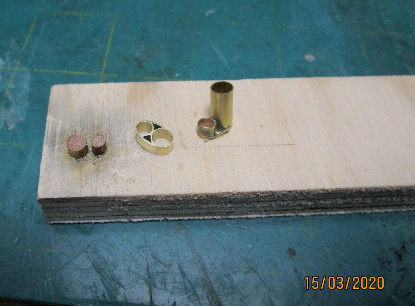
Some small updates as I have been somewhat delayed/distracted rebuilding a new computer. WRT to the Contract calling for 'Cranes" (see post #513), I decided to go with a gooseneck davit, as nothing more complicate would have been need. The photo shows one in situ with a temporary ash bucket. I will replace that with a metal one (wood or canvas I think will have been burnt when removing ash with possible hot embers still in it). I have also made a start on the bowsprit. I have shaped it (and the combined jibbooms - but the latter broke ) and I now am in the process of adding fittings (heel stop etc) which is not shown, and starting on the ironwork. The photos show the Bowsprit Cap in two stages of its manufacture. I used a jig (two dowels appropriately spaced in some scrap wood to hold the brass tube while I soldered them together and added the sides, then filed them. The first photo sows the assembly after it has been parted off with a dental cutting (separation) disk (much stronger and better than the standard Dremel disks)). I have soldered on the base lug with two hole for the Bobstay (after hole) and for the martingale (forward hoe), and two of the side lugs for guys etc. Two more lugs to be added, plus two 'horns' at the top for the man ropes. The side lugs are copper wire which I am filing flat after soldering to give the impression of flat forged lugs. Very fiddly at this scale but getting there without blowing the lot apart as I solder the lugs into drilled holes (fingers crossed and touching wood as I say that). I still need to work out how I will add the Jackstaff bracket; then a LOT of cleaning up before blackening. The form and structure of the Cap is based on drawings by Underhill. cheers Pat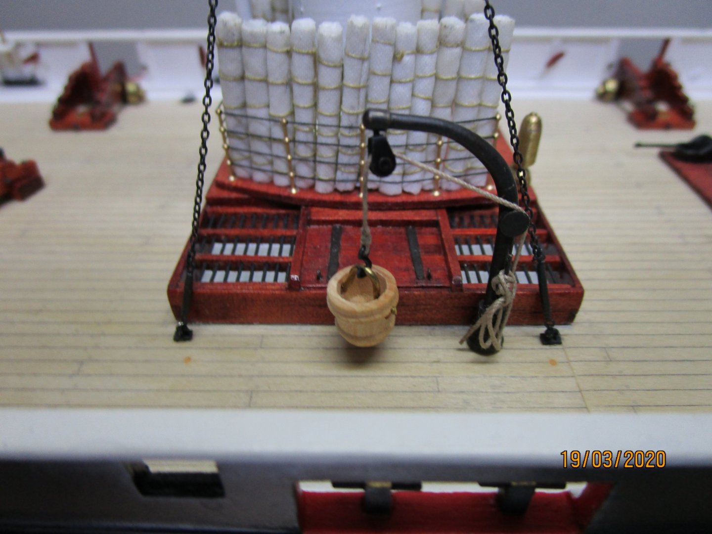

- 1,008 replies
-
- 14
-

-
- gun dispatch vessel
- victoria
- (and 2 more)
-
As good a 'solution' as any could determine, and it makes some sense Keith. cheers Pat
-
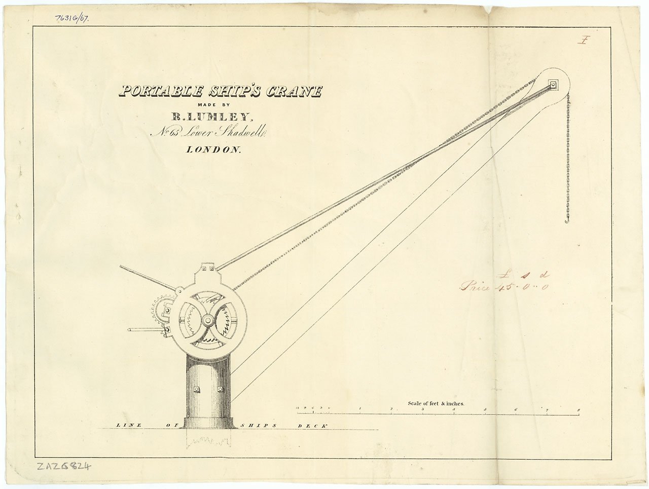
You are probably right on the object not being a crane Keith. To clarify, I should have said the 'pedestal' for a crane. Like the base/pedestal of this one in the thumbnail (credit: NMM Collections ZAZ6824) - the top/arm part may have been a lot smaller though and removed when not in use? All that said though, your other considerations seems to put paid to that suggestion I hope you can find an answer to that one. cheers Pat
-
HMCSS Victoria 1855 by BANYAN - 1:72
BANYAN replied to BANYAN's topic in - Build logs for subjects built 1851 - 1900
Hi Keith, a very interesting question. 1:120 - wow - respect! I am a masochist of sorts in that I often let my ambitions/dreams get in the way of reality. When it comes to detail, I feel that the more I can add the better (feel compelled as you say), but often I am forced into a reality check as there is only so much that can be achieved (especially with my amateurish skills) at this scale (let alone 1:120) - If I can do it it goes on and I will try many times before submitting to 'failure'. More often than not this is some minor/small detail on an item. As an example, I am currently grappling with 'compressors' fitted to the pivot gun, very difficult as they are only 4mm x 2.5mm with rails/sides only .5mm thick. These may end up being slightly oversized and only the basic form produced/used - time will tell. The real trick I think is establishing some form of threshold as you have done and simply get on with it. Thanks for looking in. Pat- 1,008 replies
-
- 5
-
-
- gun dispatch vessel
- victoria
- (and 2 more)
-
HMCSS Victoria 1855 by BANYAN - 1:72
BANYAN replied to BANYAN's topic in - Build logs for subjects built 1851 - 1900
Welcome to 1:72 club then Tony, if there is anything I can help out with just holler. By necessity I am having to do a lot of research on ships of this era so if I can minimise your research efforts, happy to share what I have assembled. cheers Pat- 1,008 replies
-
- 3
-
-
- gun dispatch vessel
- victoria
- (and 2 more)
-
Hi Keith, somehow I have missed this log; apologies. I will have to be careful not to mix the two Keith's up Great to see another model of a ship of this era. There are many elements in her I see in my HMCSS Victoria also. You have done a great job with her so far. That object you see may be a 'crane'. Victoria's Contract required the fitting of 2 x portable cranes for coaling and the removal of ash - your object, if a crane, look to be more likely to be a fixed type. The object you show/circled appears to be located in a position that would serve this requirement for one of the stoke holes at least? If it is a crane, there would possibly have been another also, I am sure they will have been used for other purposes such as storing ship. A search of the NMM elicited two designs for portable deck cranes in the 1850s, but they were generally too large for my needs, but appear to be a closer match, but not an exact match, to yours. If you search the NMM Collections>Ship Plans>Equipment for drawings ZAZ6825 and ZAZ6824 you will find the examples I mentioned. cheers, and stay safe Pat
-
HMCSS Victoria 1855 by BANYAN - 1:72
BANYAN replied to BANYAN's topic in - Build logs for subjects built 1851 - 1900
Hi Tony; a very subjective question as it depends on how much detail you wish to show and are capable of achieving. The real artist in this scale is Ed Tosti (Young America) who achieves even better detail. See what Wefalck also achieves at much smaller scale For models where the overall model size is the driver, I find 1:72 is a good compromise scale. There are also some commercial/aftermarket parts available (eg copper plates) to complement my efforts, and the scale remains 'big' enough for making scratch parts with a fair degree of detail although not to the level you could achieve at 1:48 or even 1:60. Once I have determined HOW, the making soon resolves itself. but I take a fair bit of inspiration from the likes of Michael Mott, Keith Aug and Wefalck. I must admit that at times though it can be frustrating but perseverance will win through eventually. I have found using a bit of PE to make up the parts (layering etc) has been very beneficial. I am lucky there in that I am having to draw up the plans for the ship and equipment as I go so I have drawings that do not need a lot of extra work to turn into something suited to have PE done. Again I am lucky as there is a guy located here in Melbourne who does PE (rather than having to learn yet another skill). He is experienced and often spares me the time to work through the best way to create the parts (how to determine the individual parts, fold lines, shadow lines etc). For example many of the parts for the pipe/valve fittings for the Downton pumps were done this way. Overall, 1:72 is a good scale to work with, it is a good compromise between the level of detail achievable and size of the model itself; but does bring a few frustrations along for the ride cheers Pat- 1,008 replies
-
- 5
-
-
- gun dispatch vessel
- victoria
- (and 2 more)
-
The detail on those shields is remarkable Steven; you have a much steadier hand than me my friend. cheers Pat
-
Thanks for the explanation; they are among the best fittings I have seen made - you truly have a remarkable talent. Thanks for sharing Pat
-
Great to hear you are well Michael, and hopefully you and family will all continue to have good health. I am sure many would be interested in your 'other activity' Pat
-
Hopefully you may be able to get the model out of 'detention' John so that you can work on her at home. Good luck and best health to all! Pat
-
Not much more to do now Rob; looking good! cheers Pat
- 1,208 replies
-
- 1
-
-
- great republic
- clipper
- (and 1 more)
-
Nice vessel to model James; with your skills it should develop into a very nice model. Monitoring with interest cheers Pat
- 100 replies
-
- 2
-
-
- zulu
- vanguard models
- (and 2 more)
-
Stunning work! Did you make those thimbles, clew hooks etc yourself? If you did, could you please show us how you did it? cheers Pat
-
Pathfinder, no worries, but as I mentioned, I am some ways of completing this research; and also, only the basic rig details will be applicable. You will need to refine my results for your own belaying plan especially. Do you have much in the way of imagery to help? Please PM me if you wish a little more detail of what I have done as it is far too large to post the details here and I wish to preserve copyright for some of it. For example, do you know if she used wire or natural cordage for her shrouds, stays etc.? cheers Pat
-
Welcome to the forum. Not sure you will find kits for those; may have to join us on the 'dark side' of scratch building. cheers Pat
-
Miniature Desk-Top Laser-Cutter
BANYAN replied to wefalck's topic in Modeling tools and Workshop Equipment
Great review and guide Eberhard, that is very useful. I am seriously thinking of ditching the PE process for this wherever I can. cheers Pat