


DocBlake
-
Posts
1,811 -
Joined
-
Last visited
Content Type
Profiles
Forums
Gallery
Events
Posts posted by DocBlake
-
-
-
-
Thanks, guys for the "likes"!
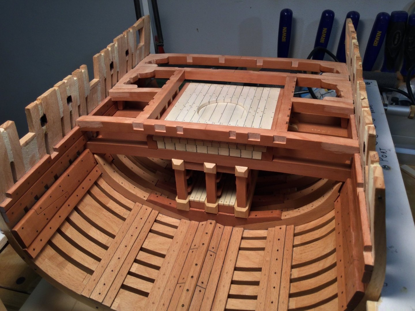
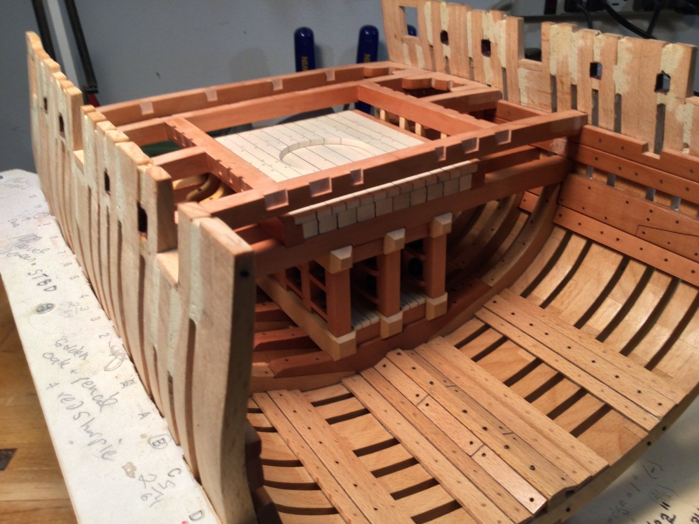
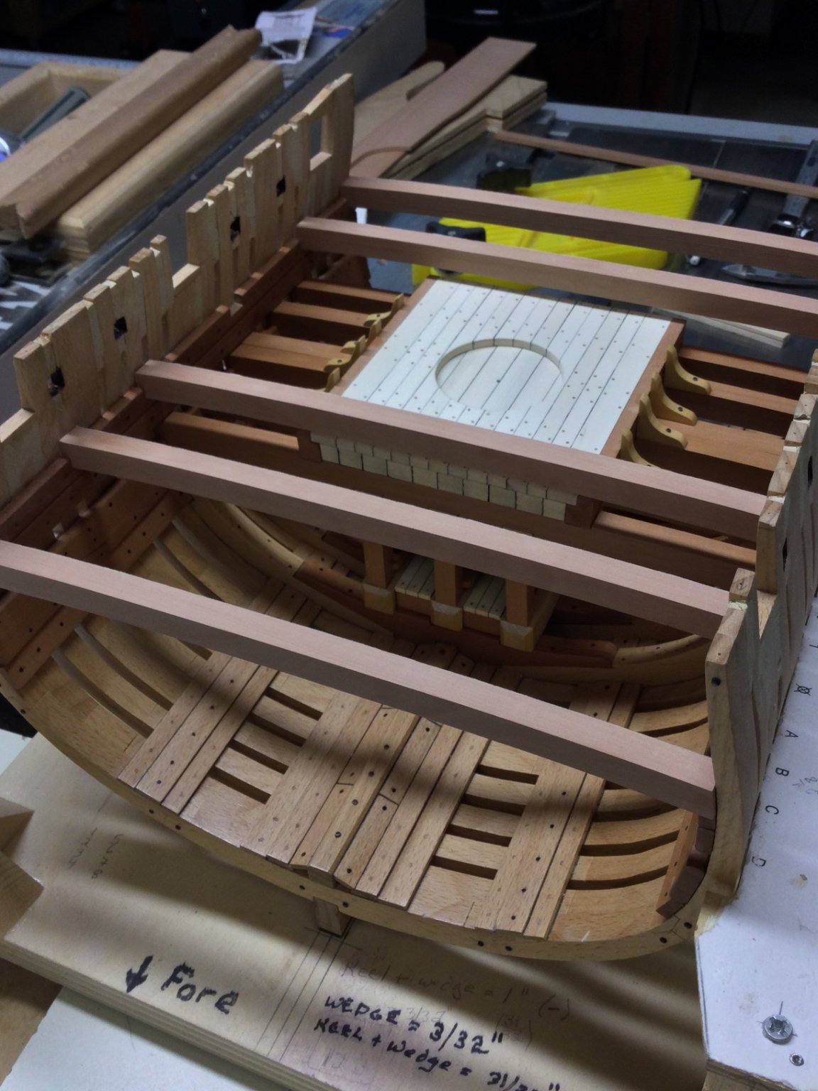
Here is where I am. I've got all the deck beams notched and have started installing them from aft forward. Because the beams sit in notches in the deck clamps, they can't move. Fitting the hanging and lodging knees is really finicky if you want a tight fit. I'll add the carlings and ledges and finish the deck up to the forward end of the mortar pit. That's where the hardest part of the deck starts: fitting the beam arms. I cut them generously and left them a bit thick. They are so long that I have to account for the deck camber.

- oneslim, GrandpaPhil, Elijah and 15 others
-
 18
18
-
-
Thanks, Jean-Paul, and thanks to all for the "likes"!
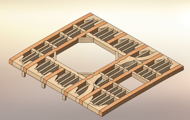
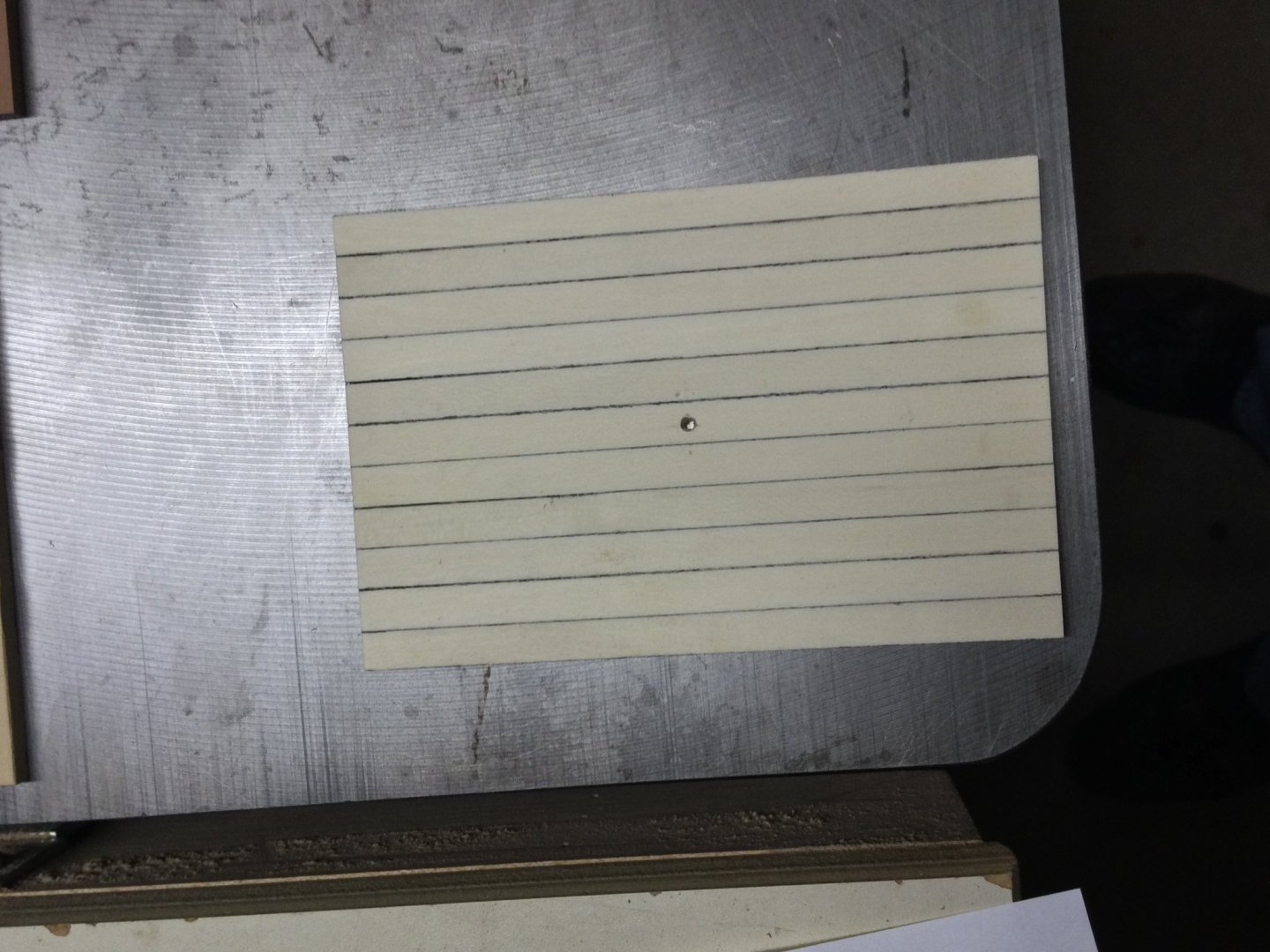
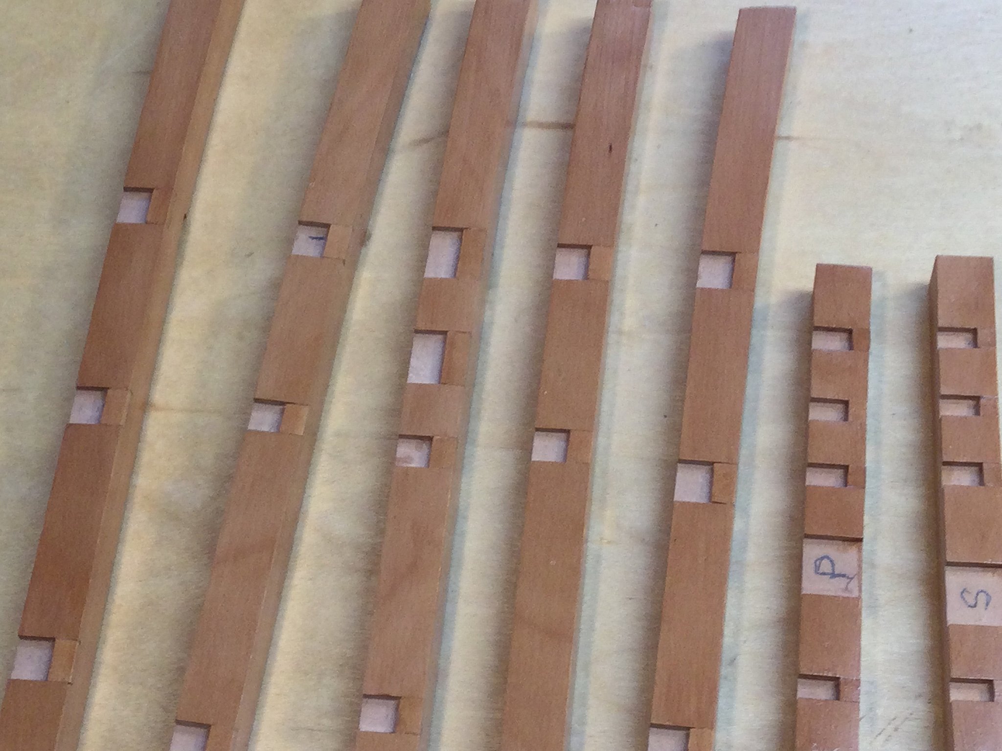
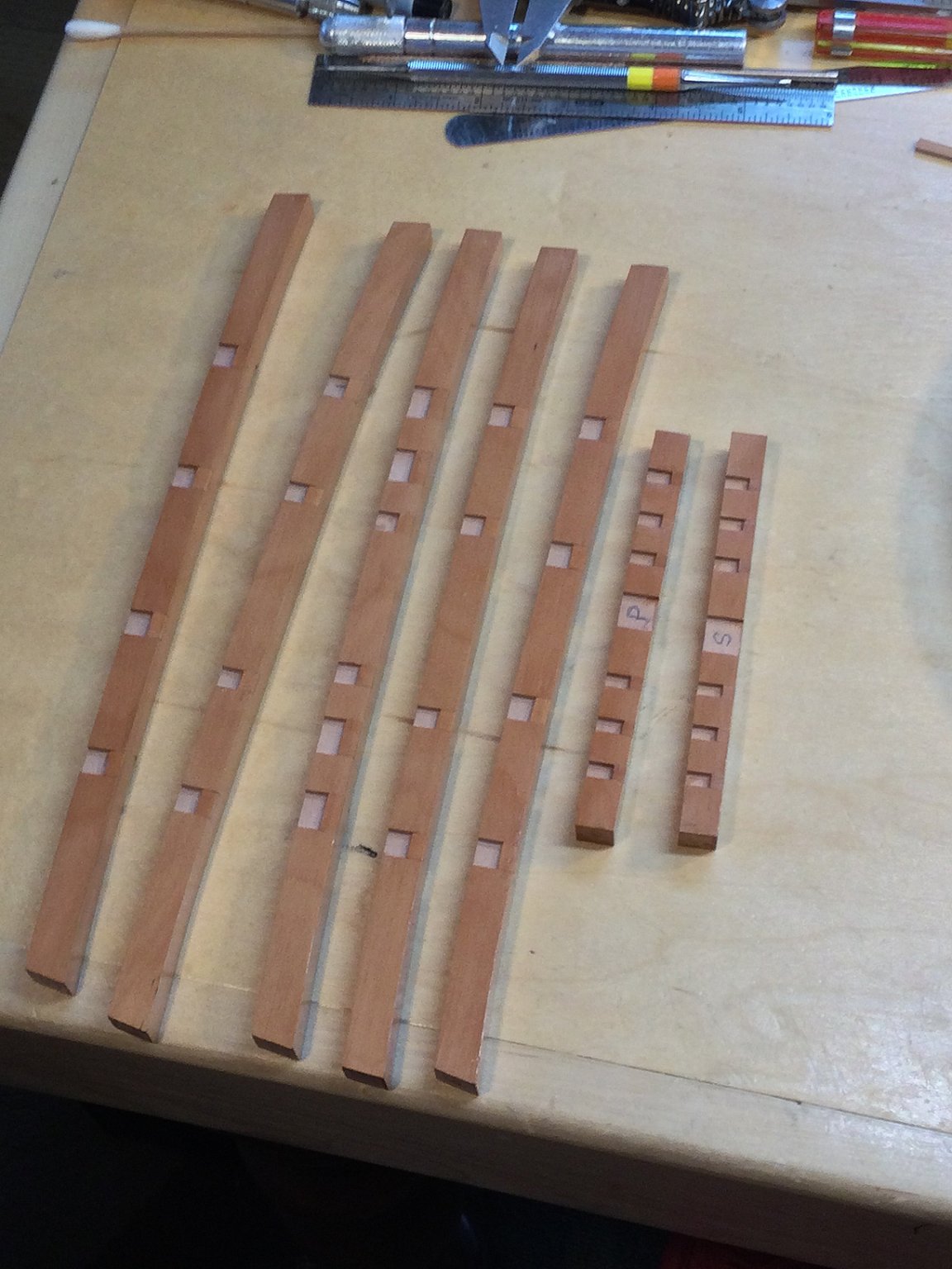
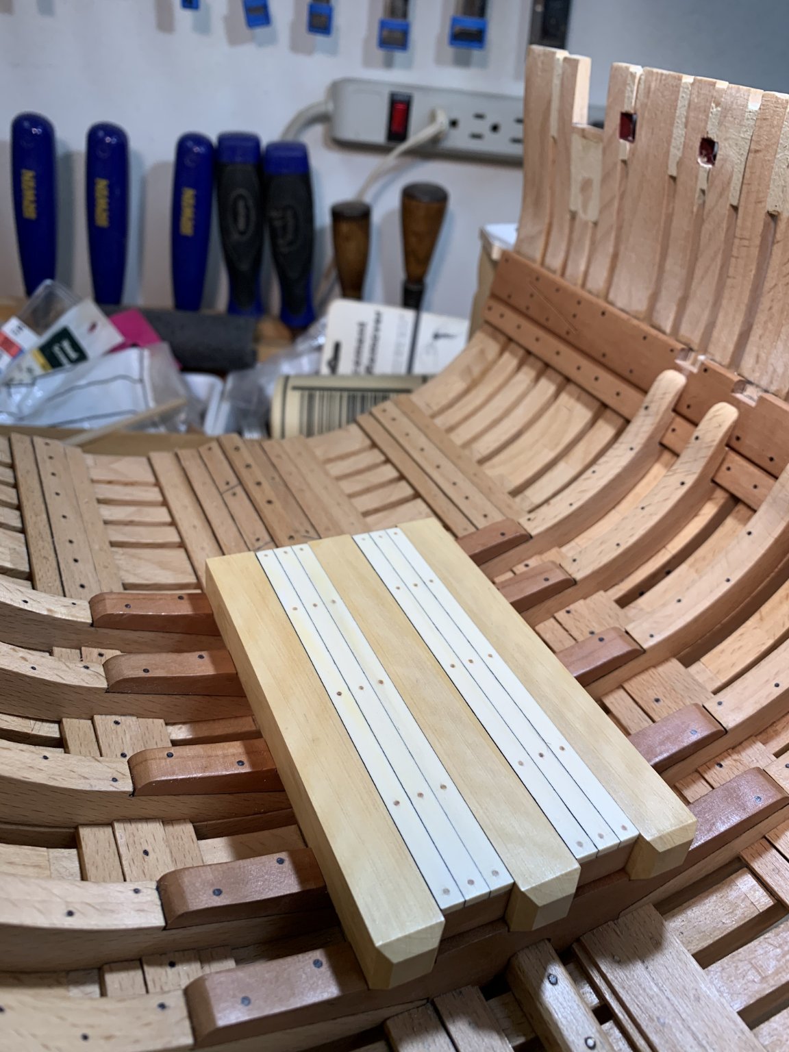
A friend and collaborator, Joseph, is doing 3-D drawings of the plans and we are making changes to simplify construction for those less experienced. This includes eliminating the rise in the frames moving aft as well as eliminating the narrowing of the hull moving aft. He also drew up the deck such that all the beams, carlings, ledges and lodging knees were the same thickness (pictured). I decided to use stopped dadoes on the beams to seat the carlings. Thus the carlings would be thinner than the beams. I'll keep the ledges and knees the same thickness as the carlings, though, to simplify construction. I think it will look fines.
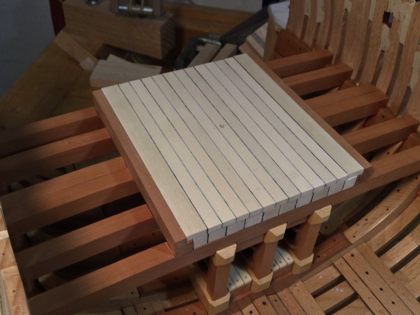
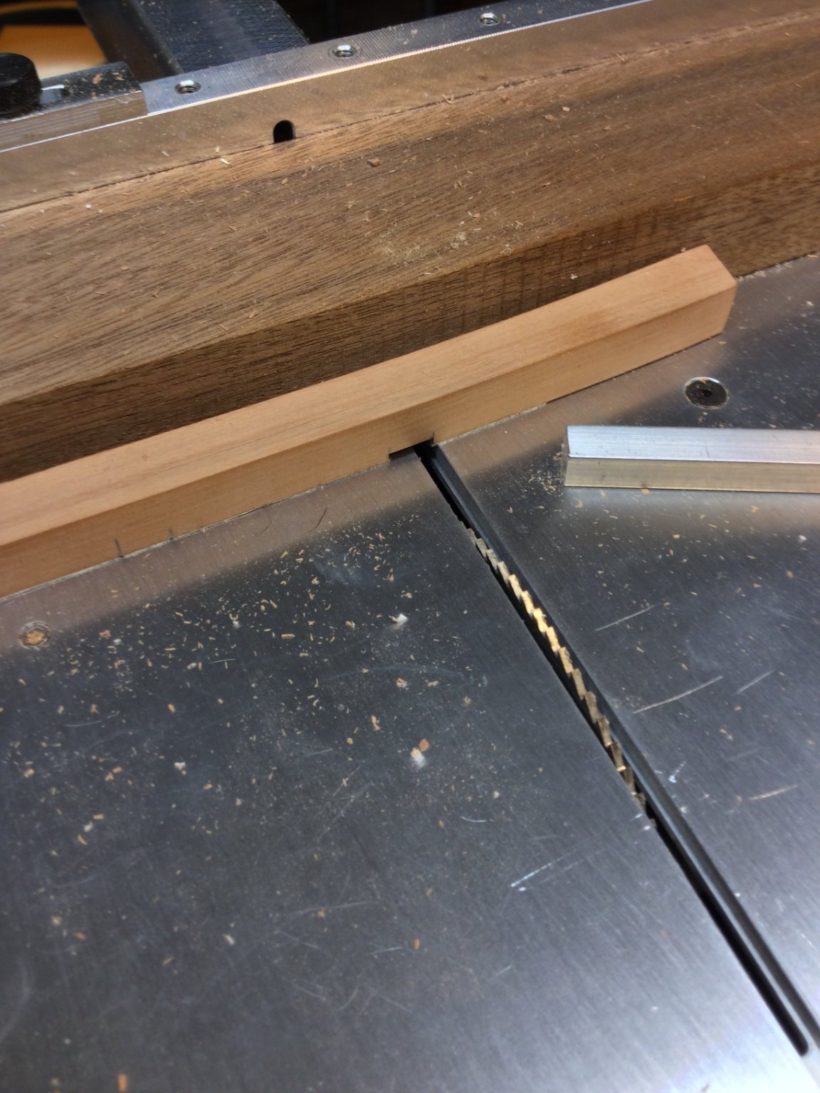
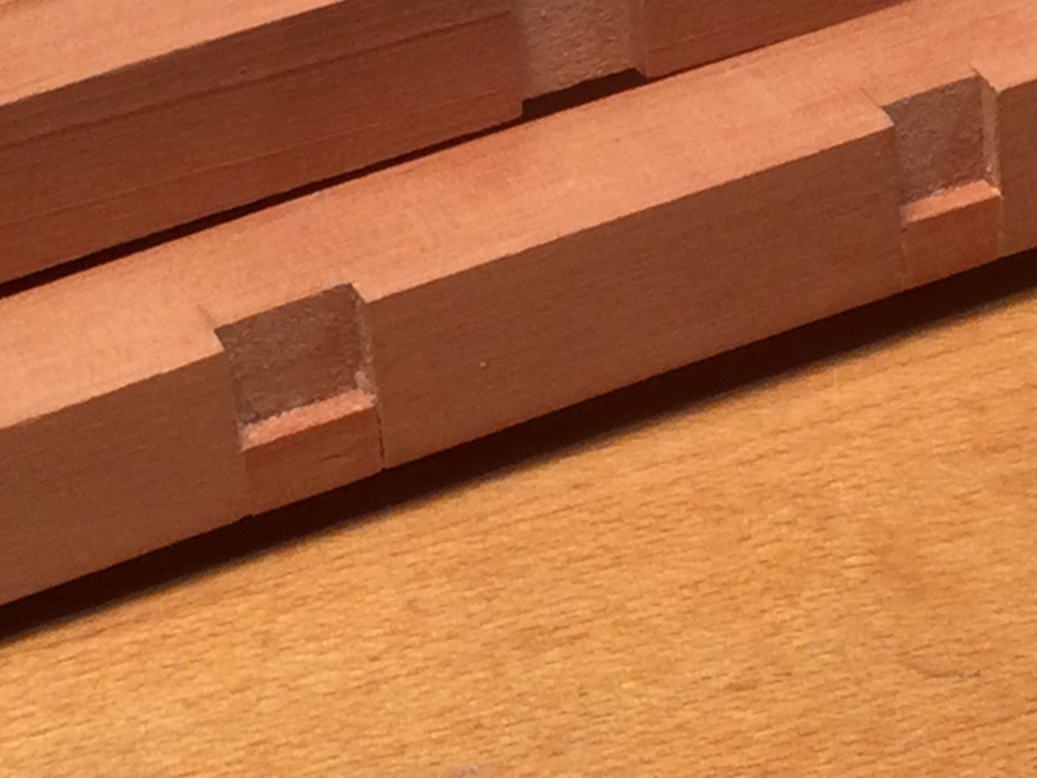
Rather than use a razor saw, chisels and a hobby knife to cut the dadoes for the carlings, I looked for an easier way. what I did was cut the dadoes all the way through the beams at a depth of 1/16". I then milled some 1/16" pear stock to the width I needed to give me stopped dadoes. These were glued in place and sanded smooth. Very easy!


- Elijah, Edwardkenway, mtaylor and 10 others
-
13
-
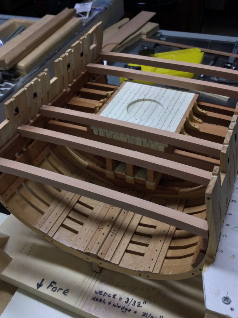
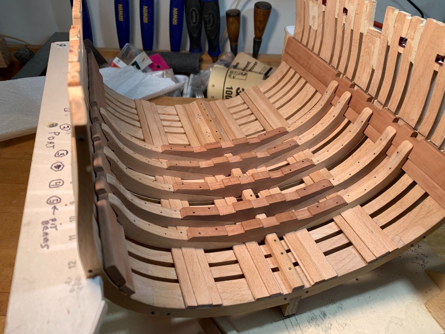
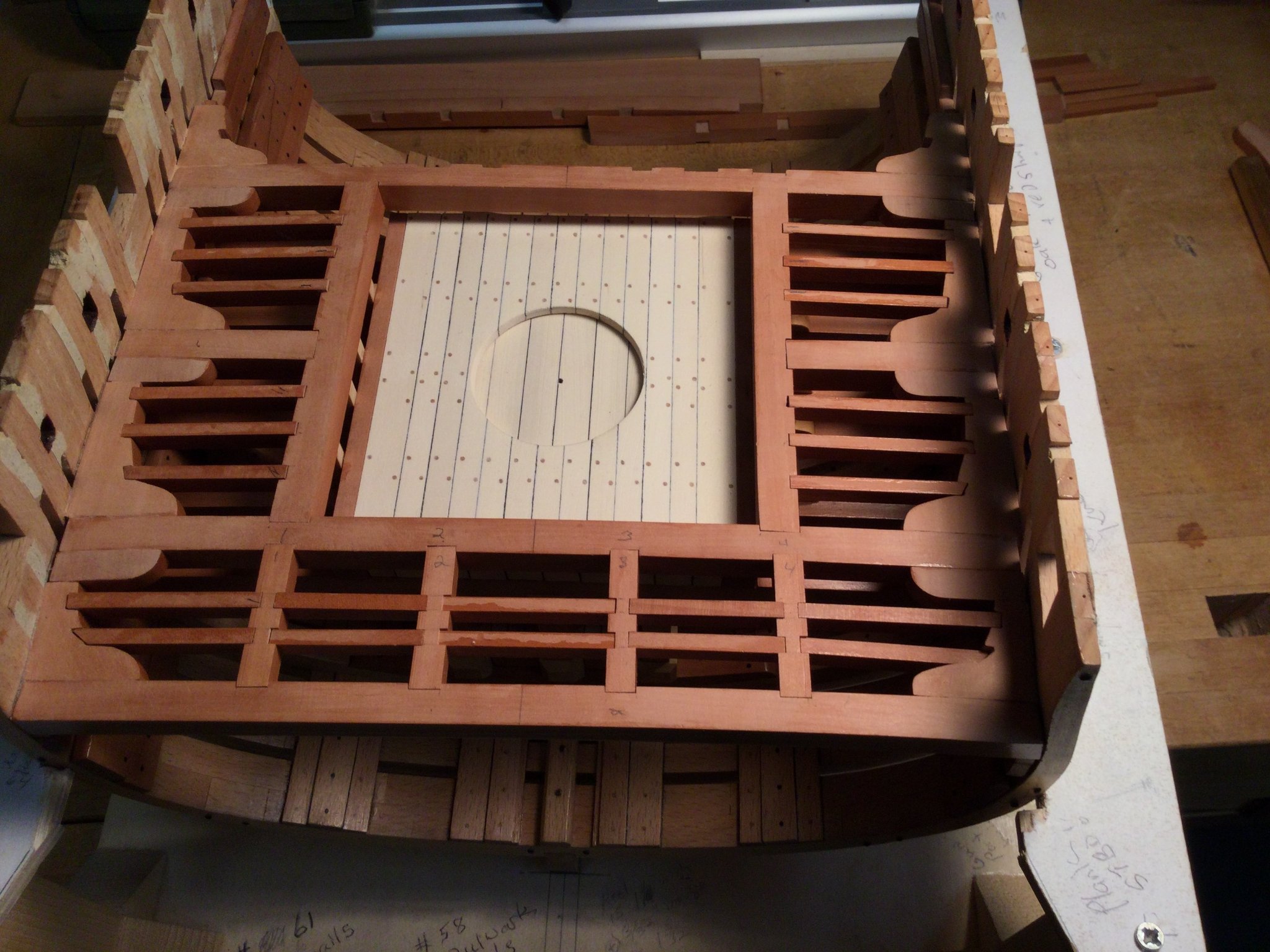
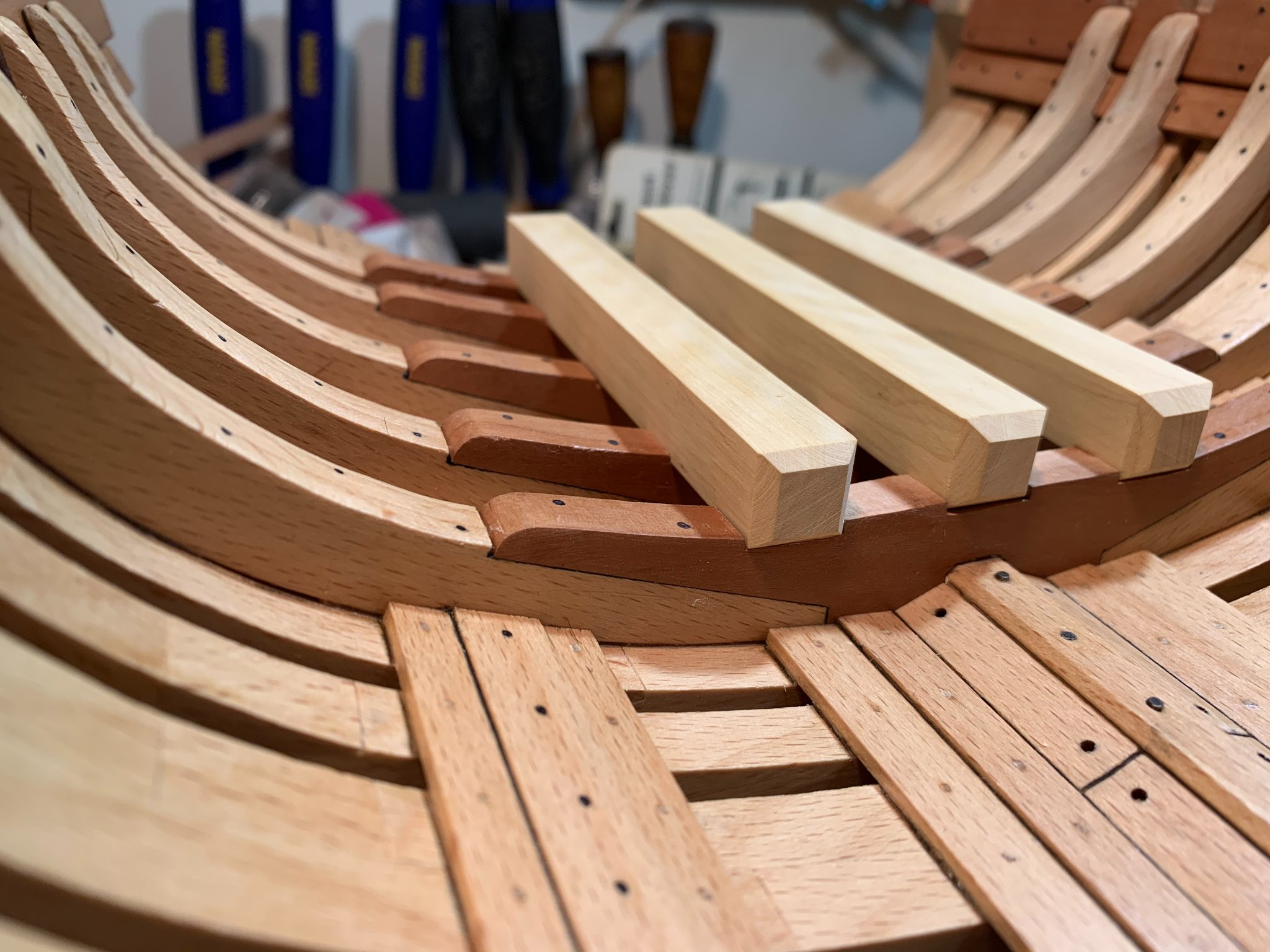
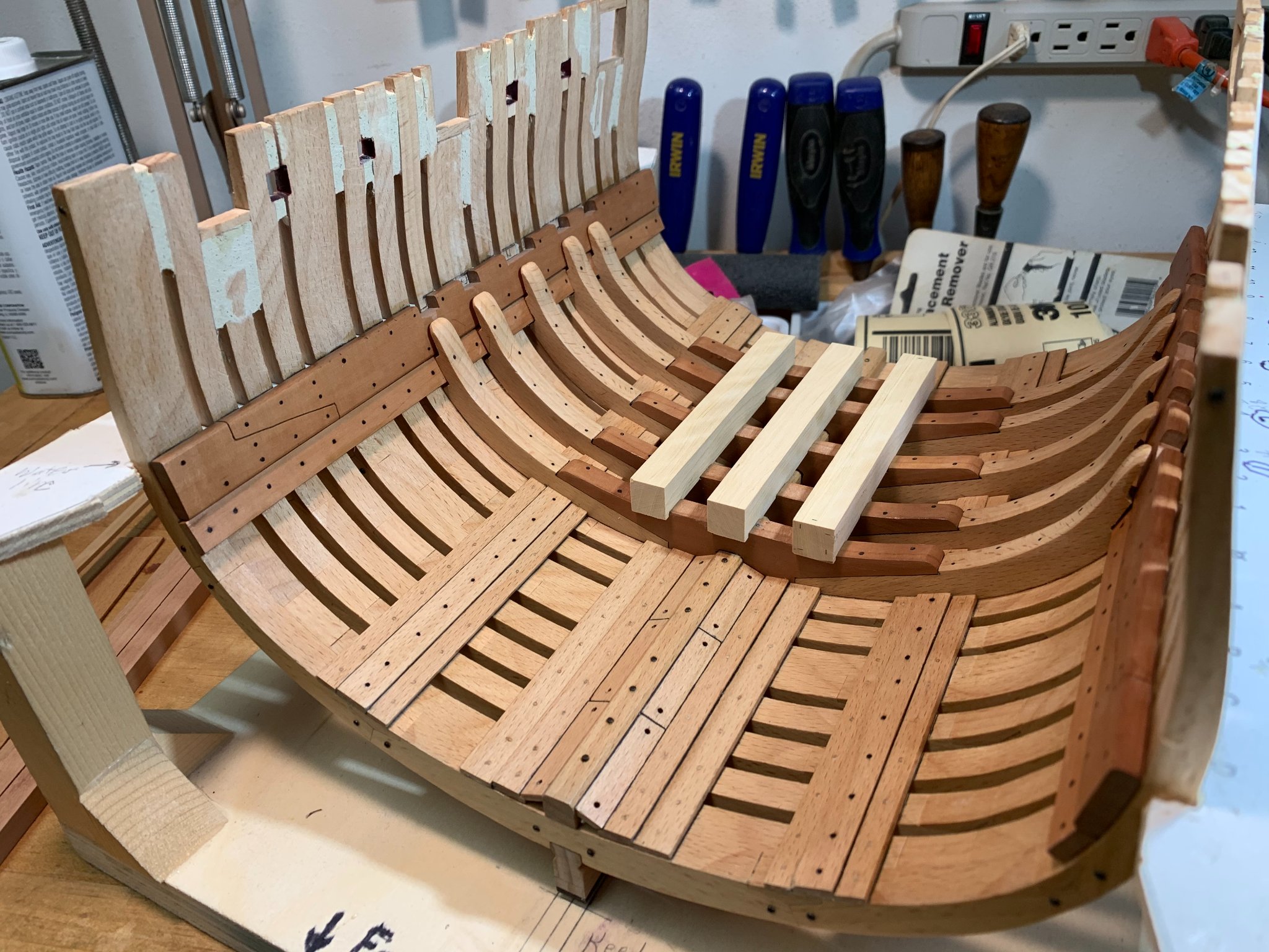
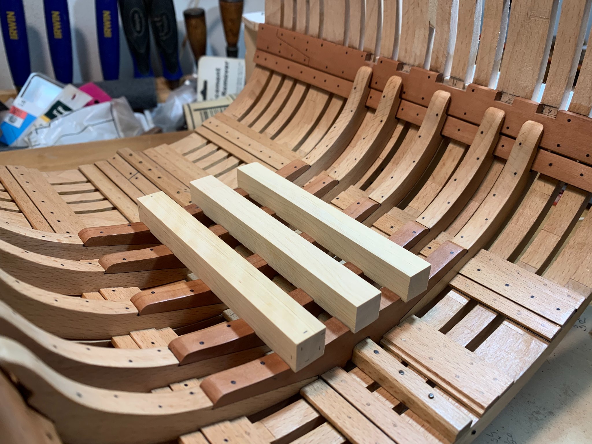
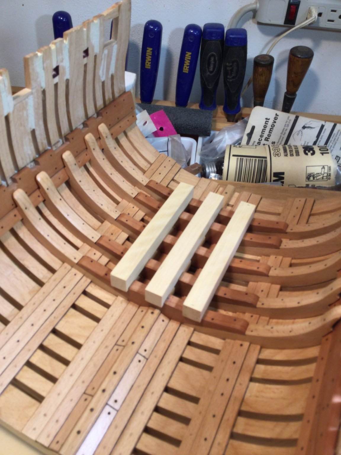
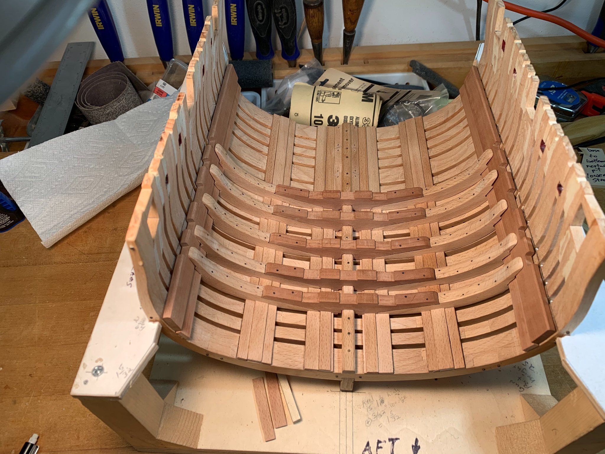
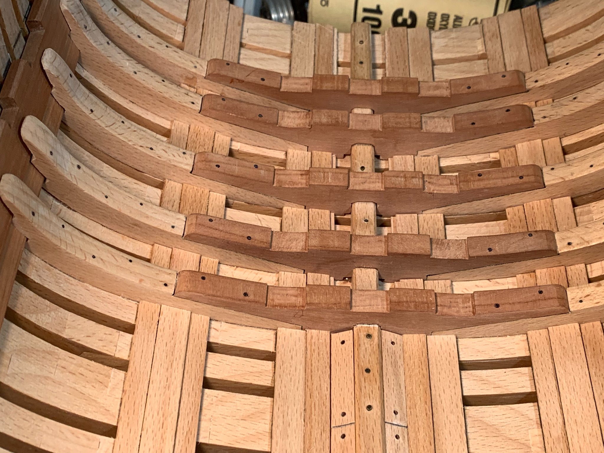
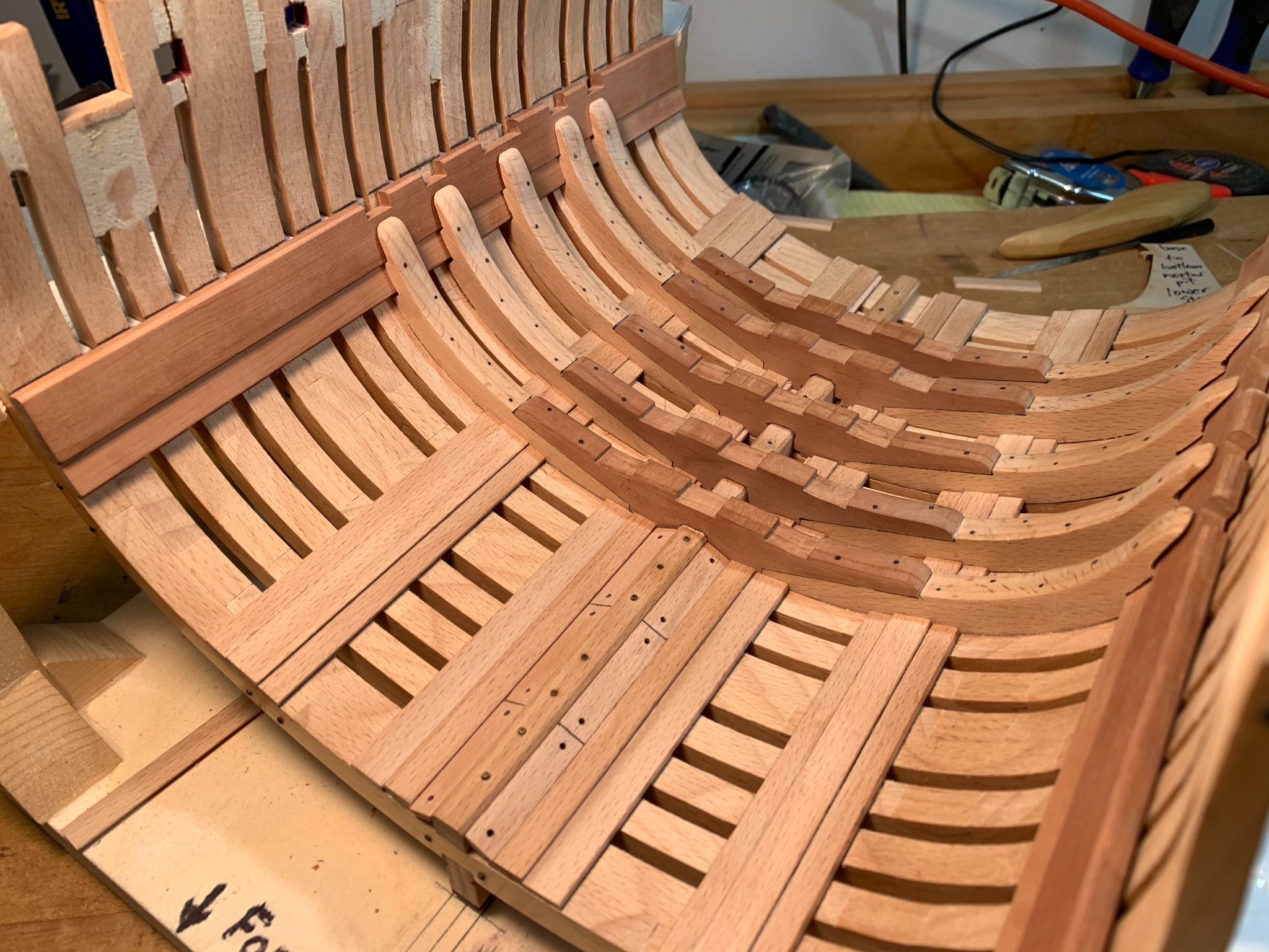
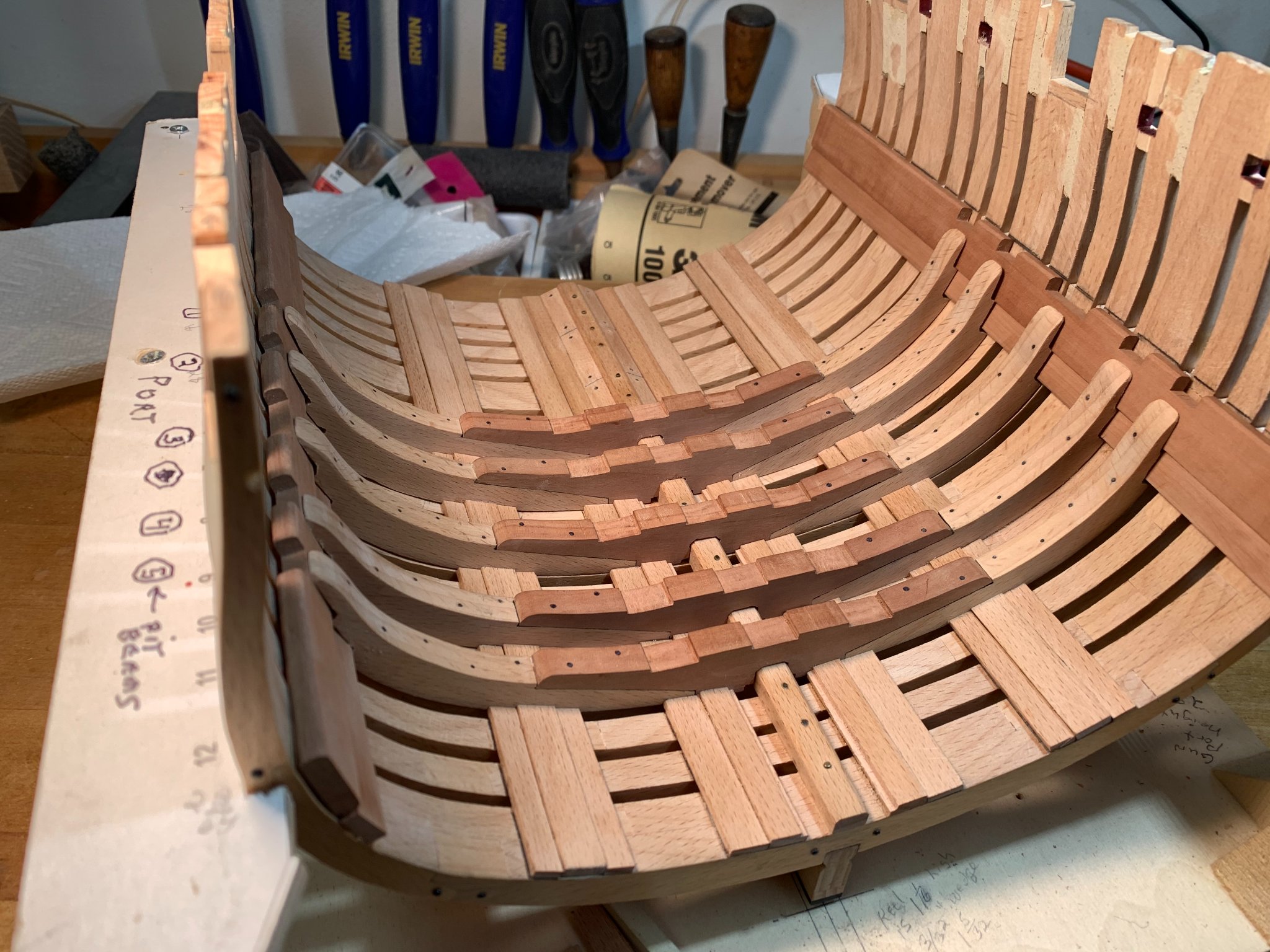
I started work on the upper deck by rubber cementing the deck beam profile templates to a sheet of 3/8" swiss pear. I used the scroll saw to cut out the beams, and sanded them smooth. Each beam is 12 scale inches square in profile!
I cut the beams slightly long and used the disk sander to sneak up on the final width. I'd like them to fit with no side- to-side play, but the fact was that due to the tumblehome of the top timbers, I had to make the final beam length a little short so they could fit into their notches on the clamps. Any side-to-side play will be taken care of by using removable shims at each end at glue up. The photos show the beams resting in place. Partial beams #4 are not yet fitted.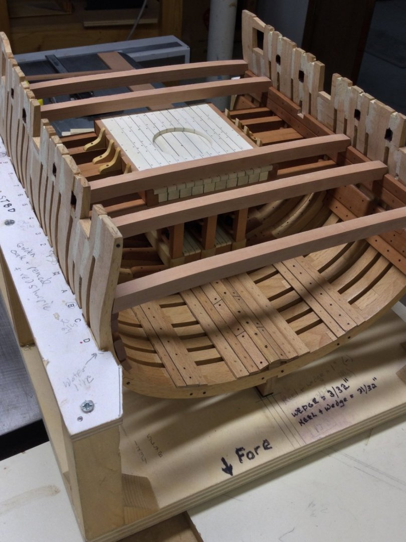
- Ryland Craze, popash42, Osmosis and 11 others
-
14
-
I cut and notched the 4 planks that make up the upper deck clamps. After bending them to the slight aft narrowing they were glued in place and treenails added. Then I cut out the eight mortar pit support knees and pinned and glued them in place.


- mtaylor, Osmosis, GrandpaPhil and 11 others
-
14
-
-
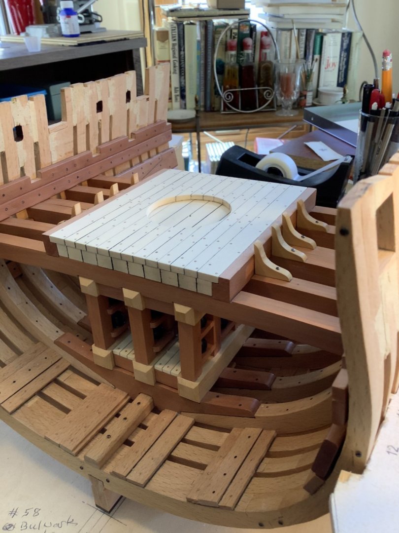
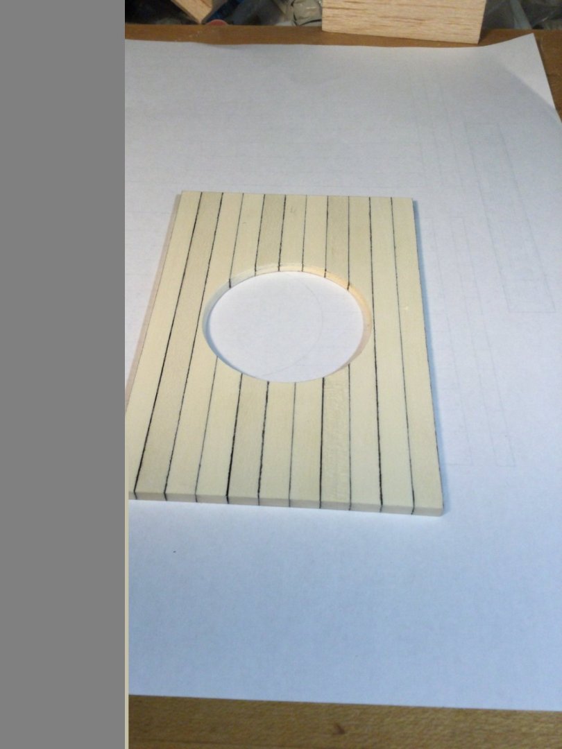
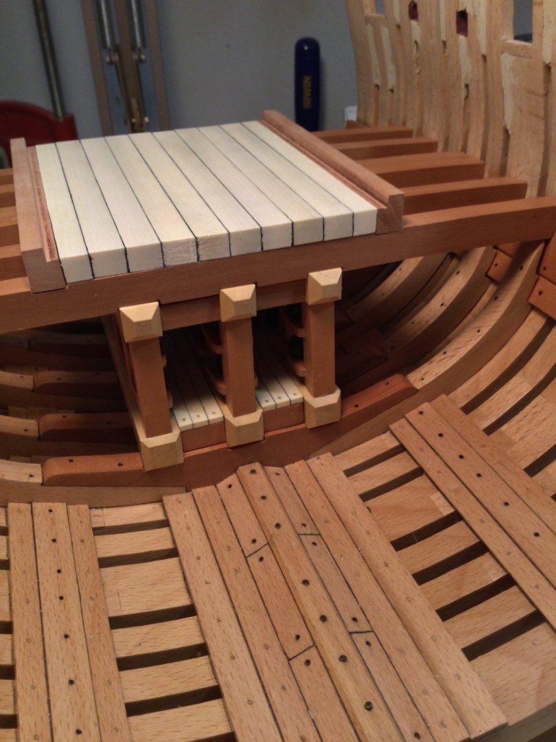
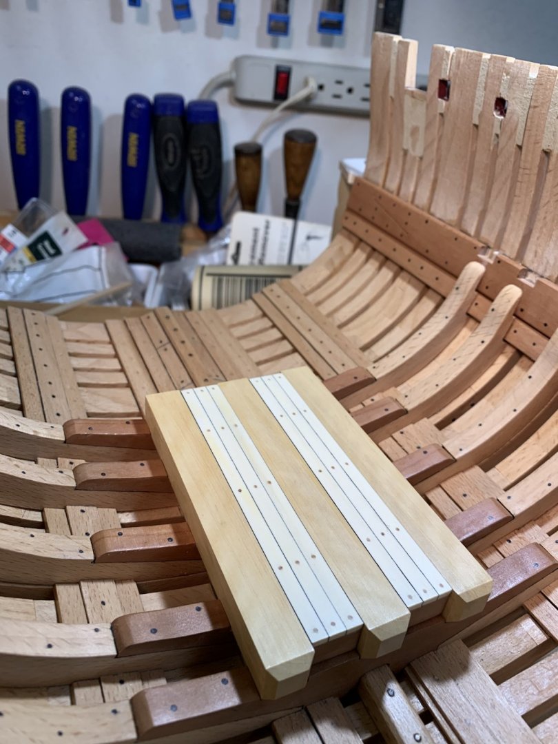
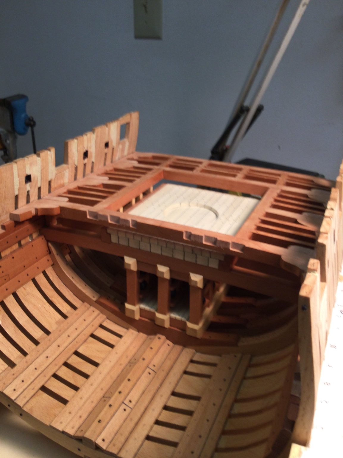
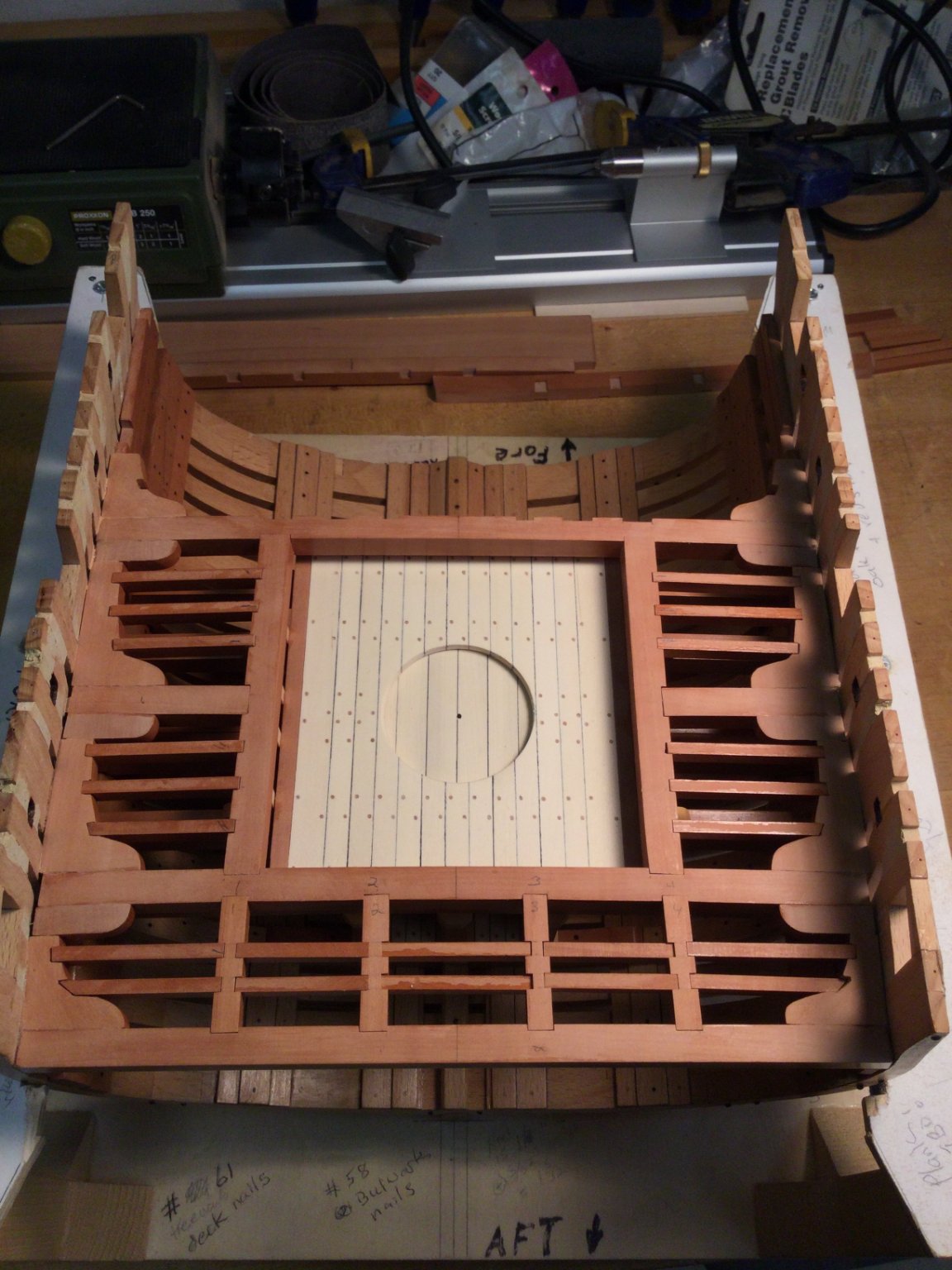
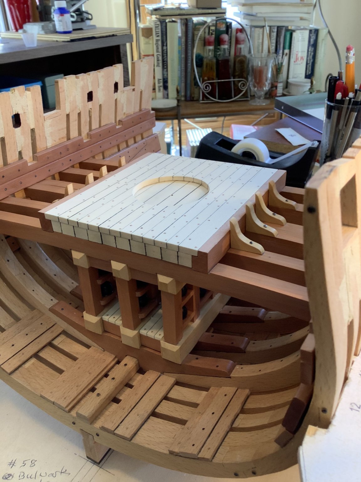
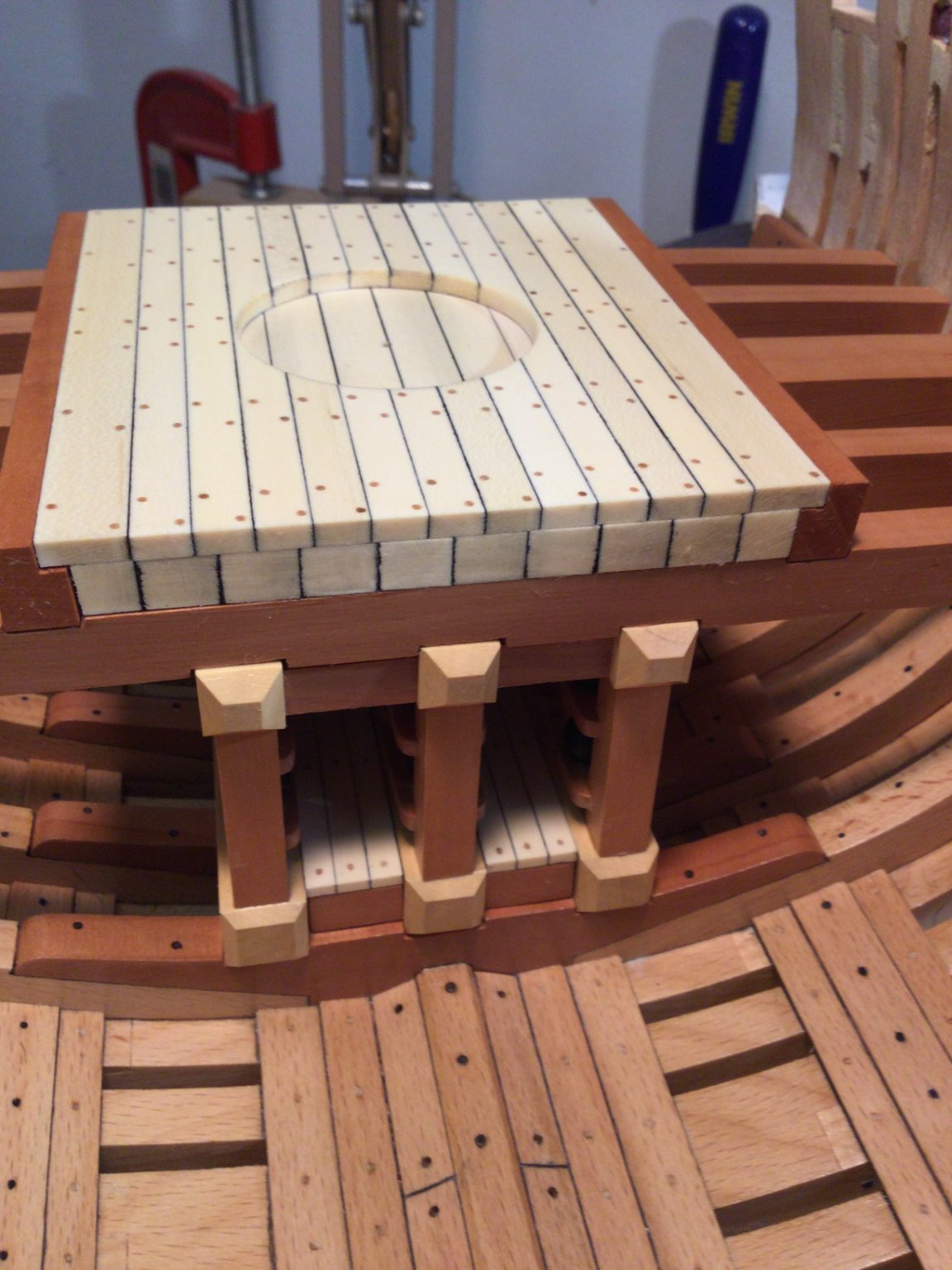
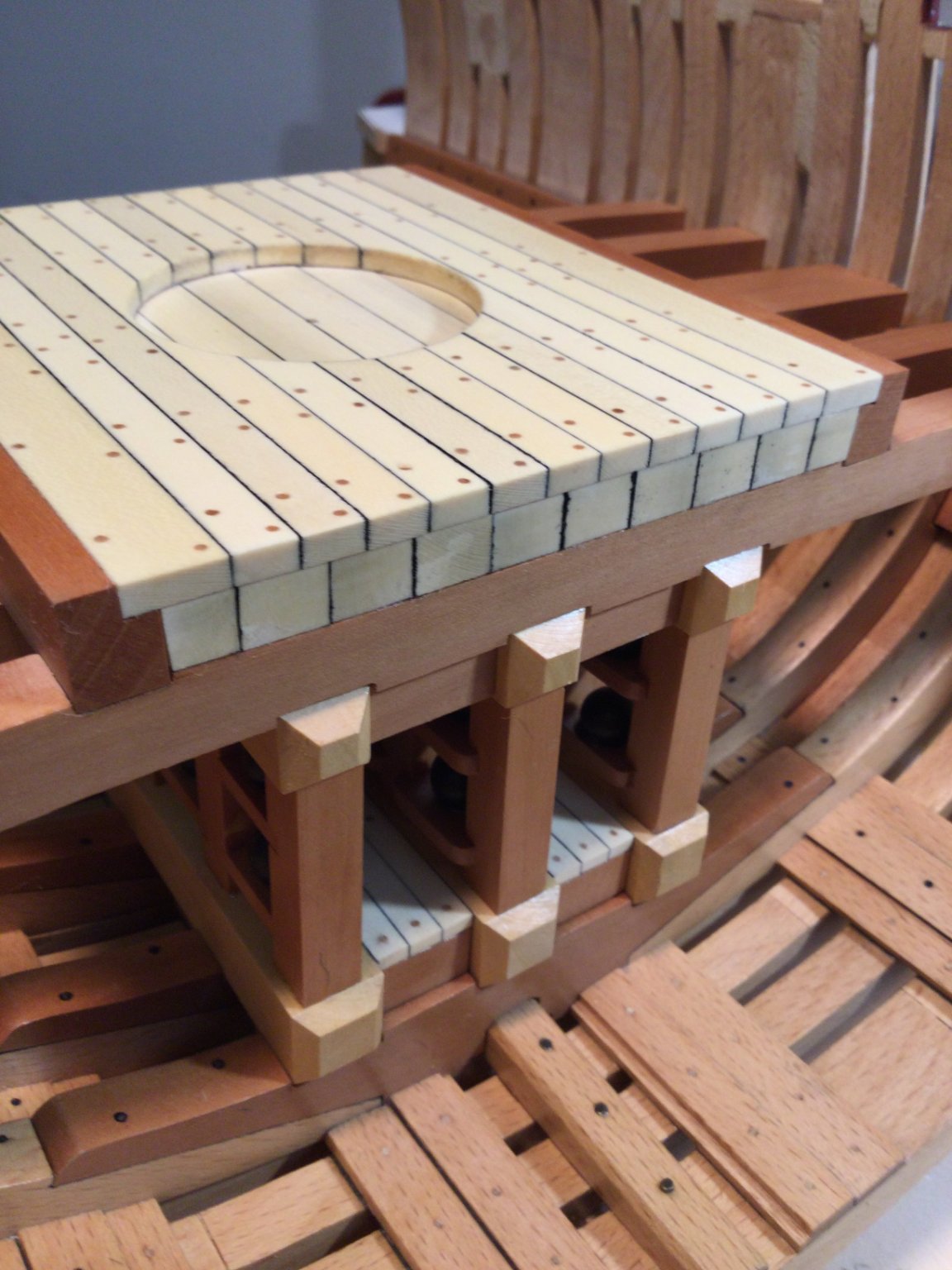
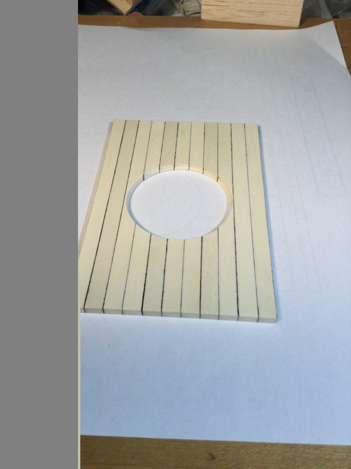
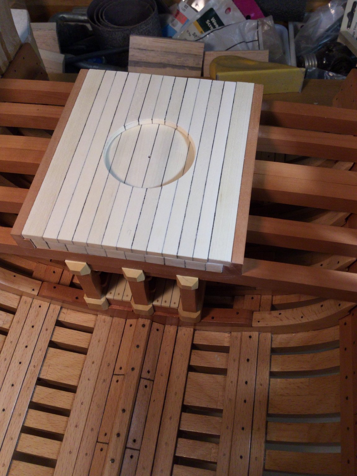
I built the secondary mortar pit deck off the model by edge gluing the planking together. I then located where the center of the circular cutout would be and drilled a hole. I transferred this location to the primary deck by putting the deck back in place and marking the primary deck with a nail through the hole.
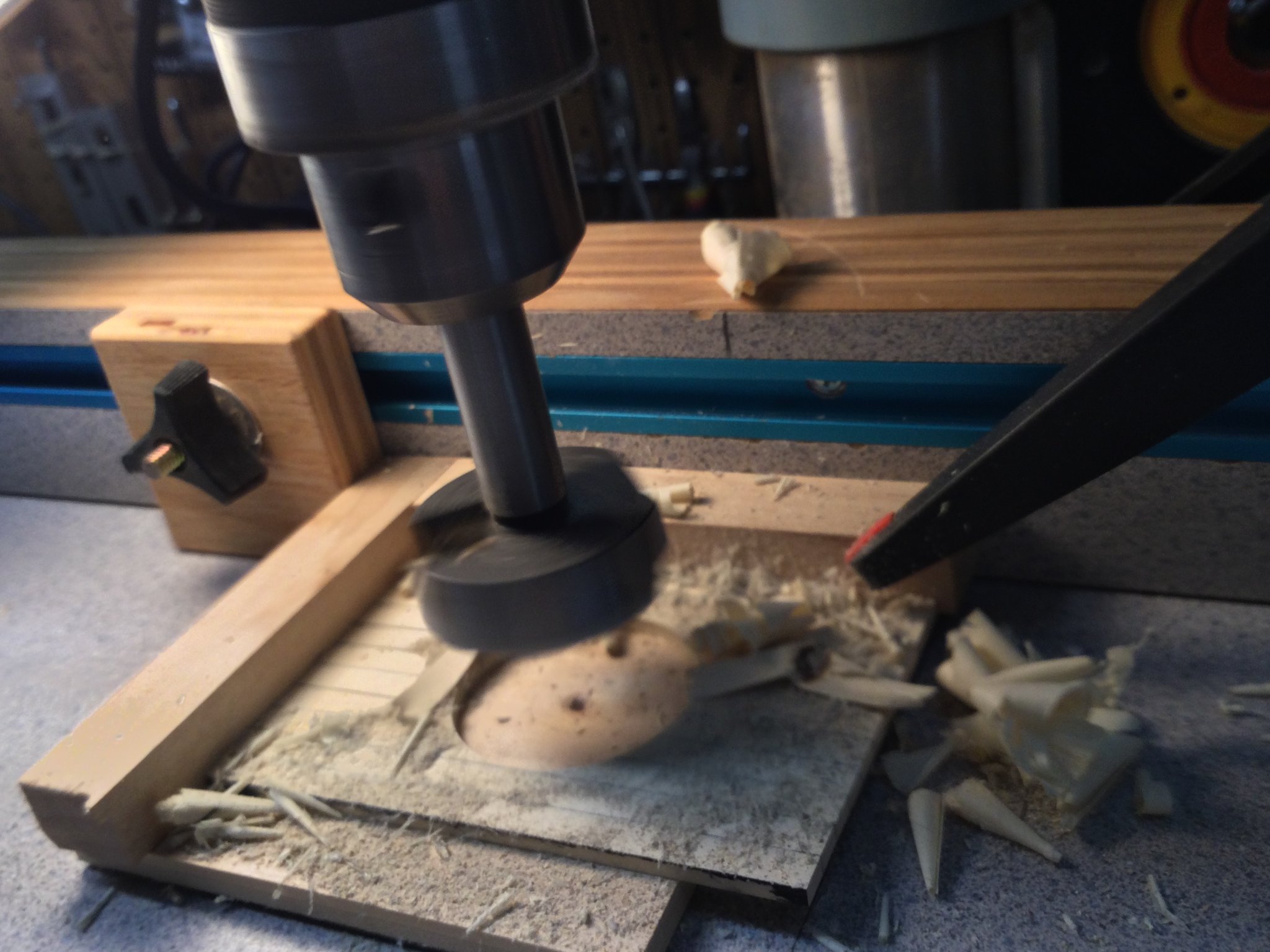
I whipped up a little jig to hold the secondary deck in place while I drilled out the circular recess with a Forstner bit. The secondary deck was glued in place.


-
Thanks, guys!
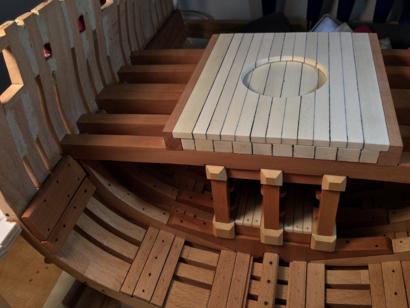
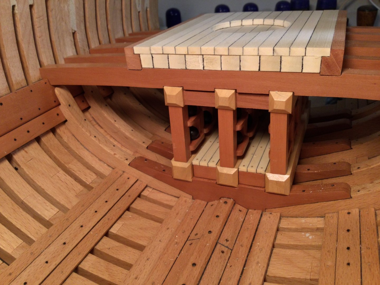
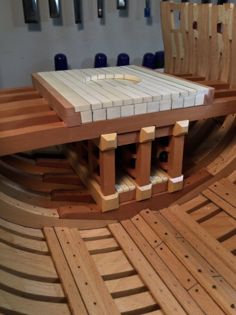
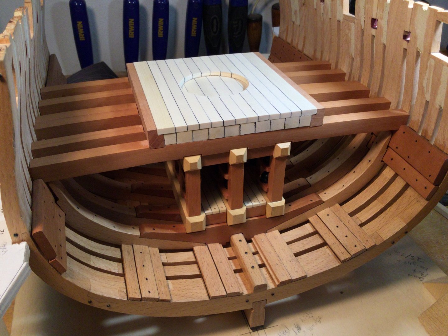
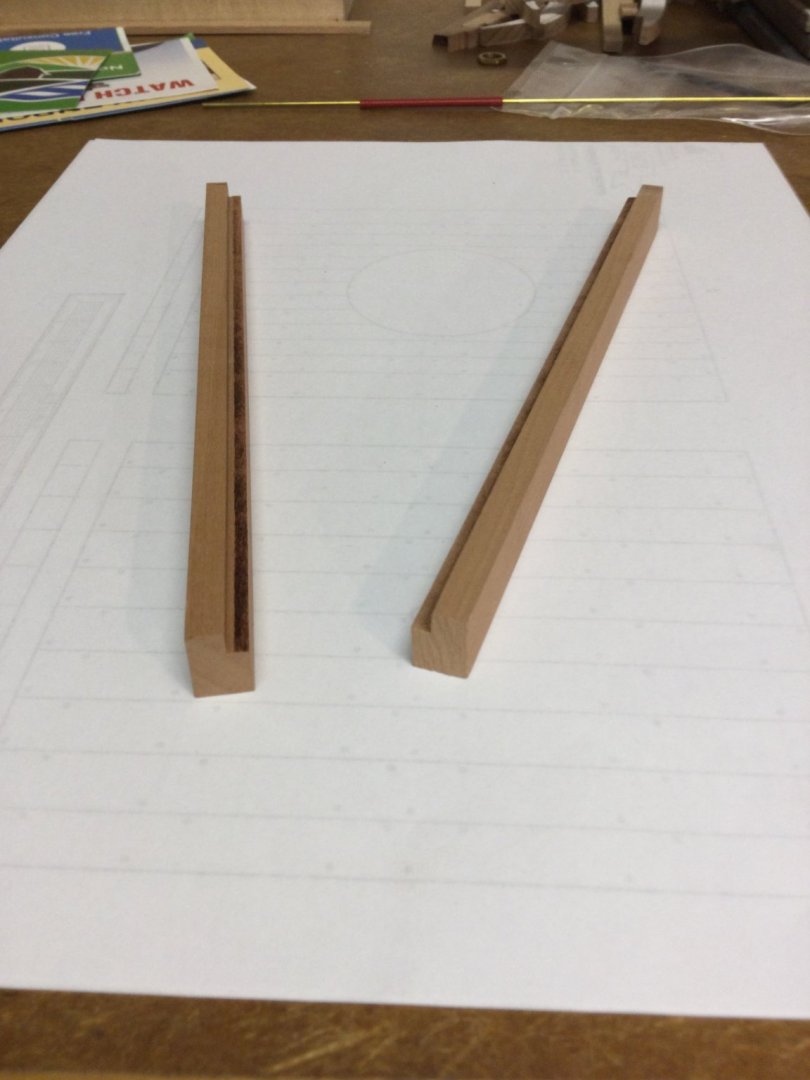
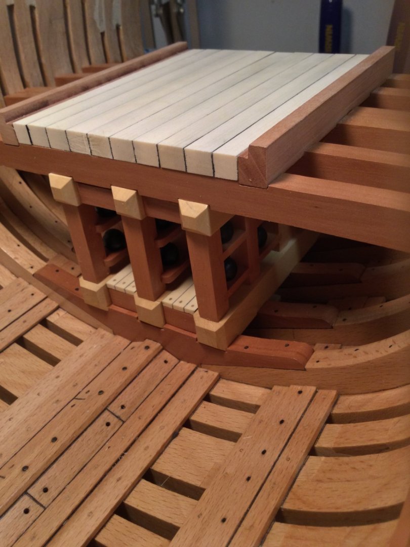
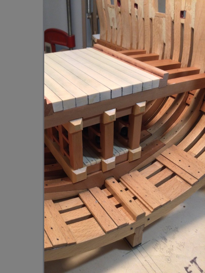
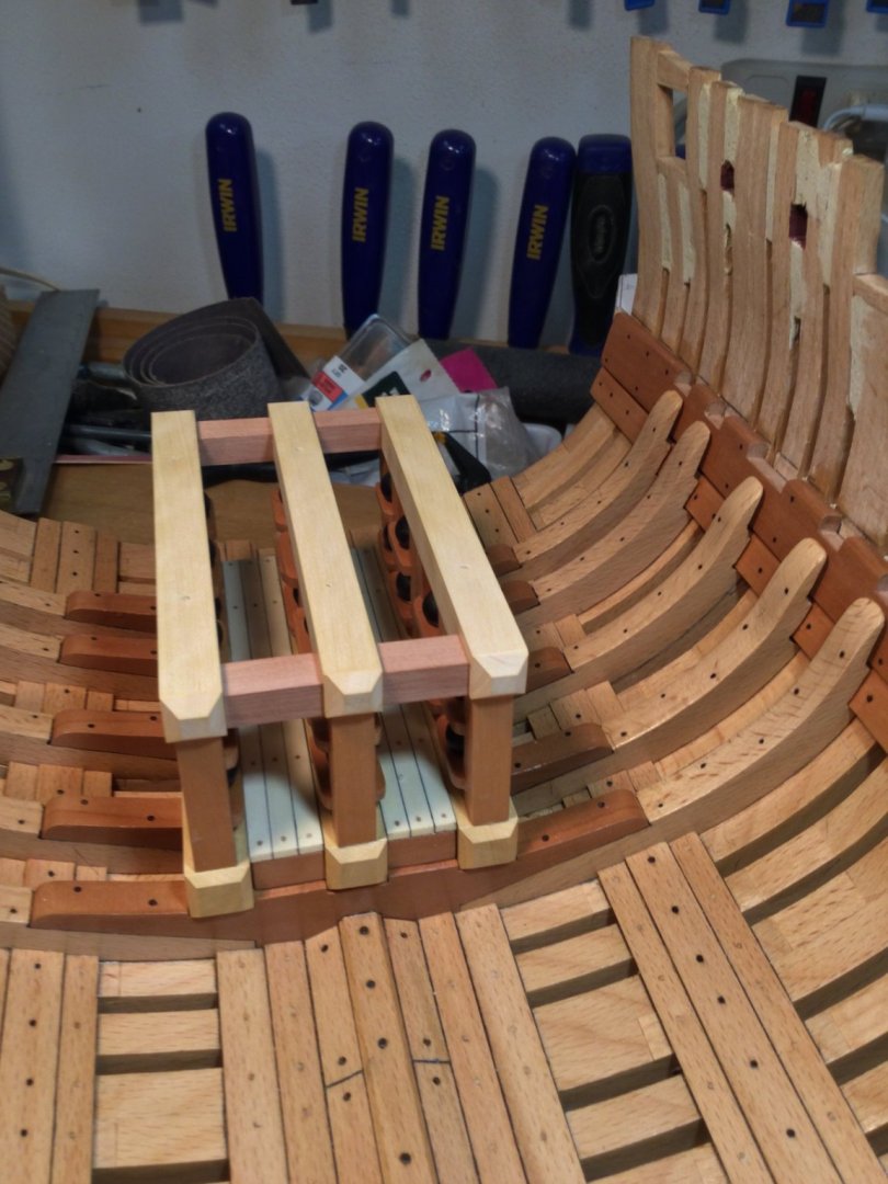
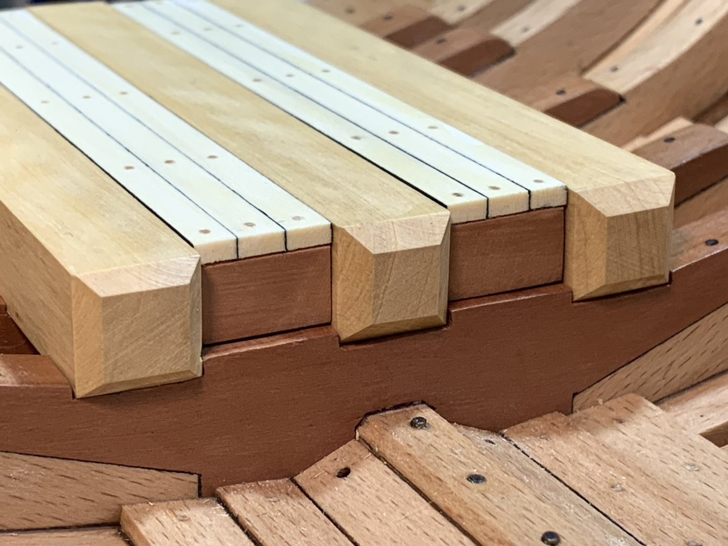
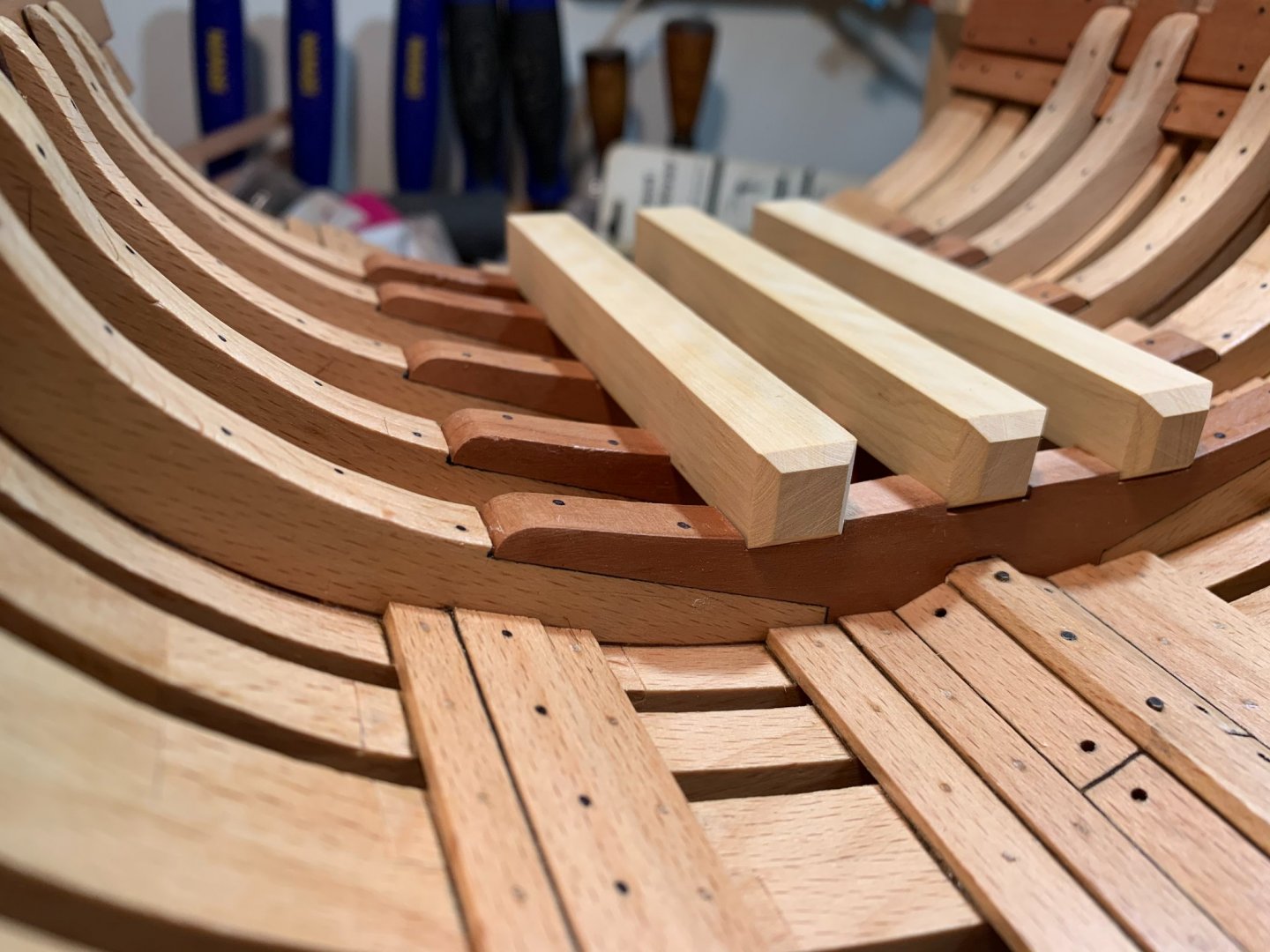
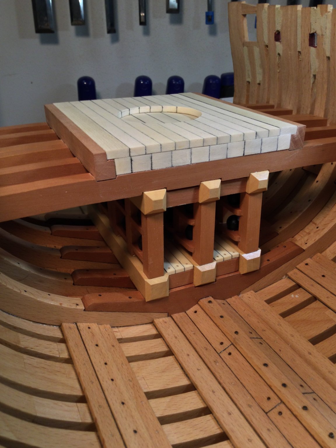
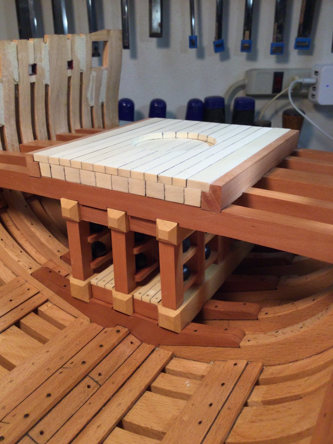
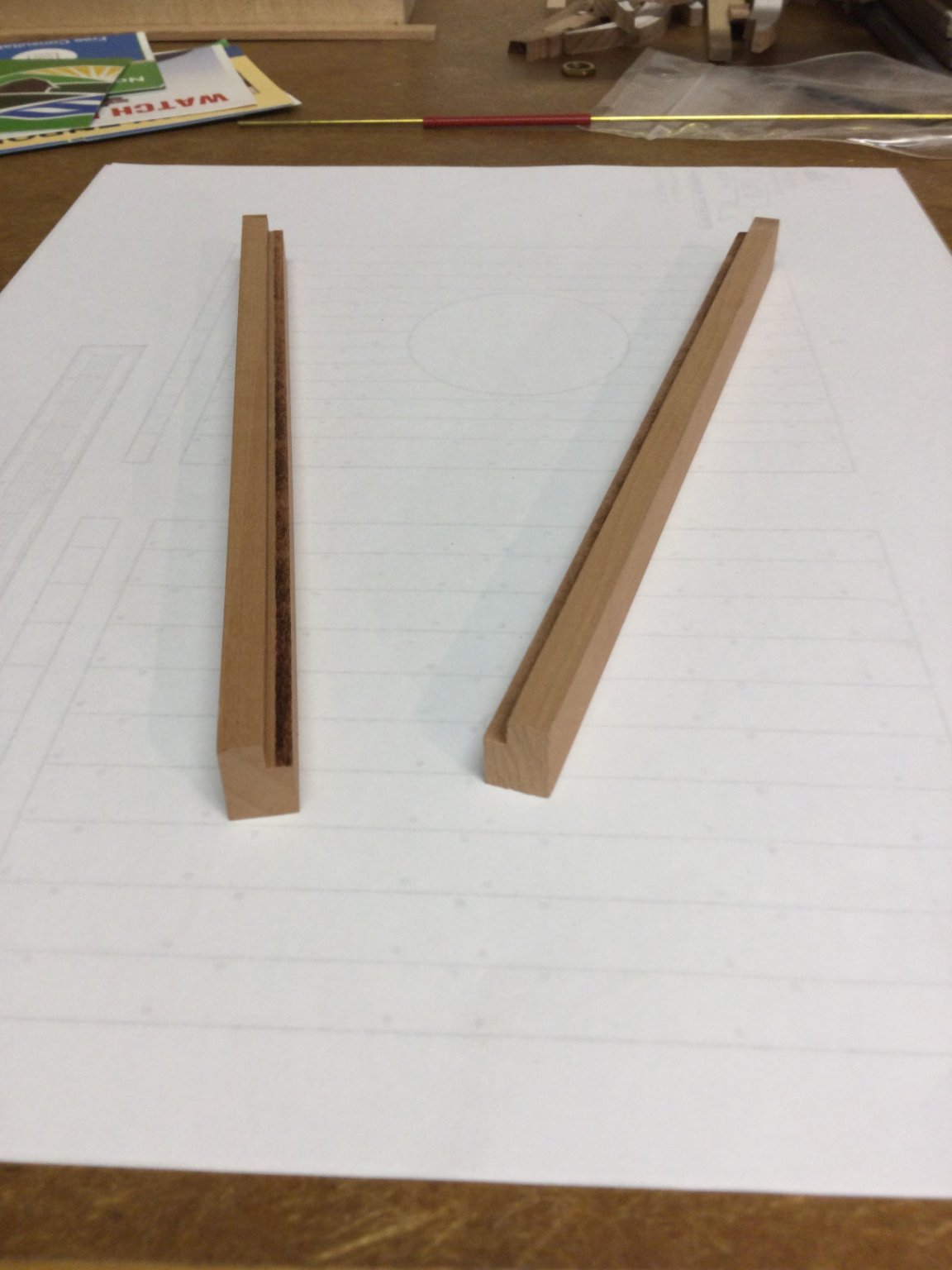
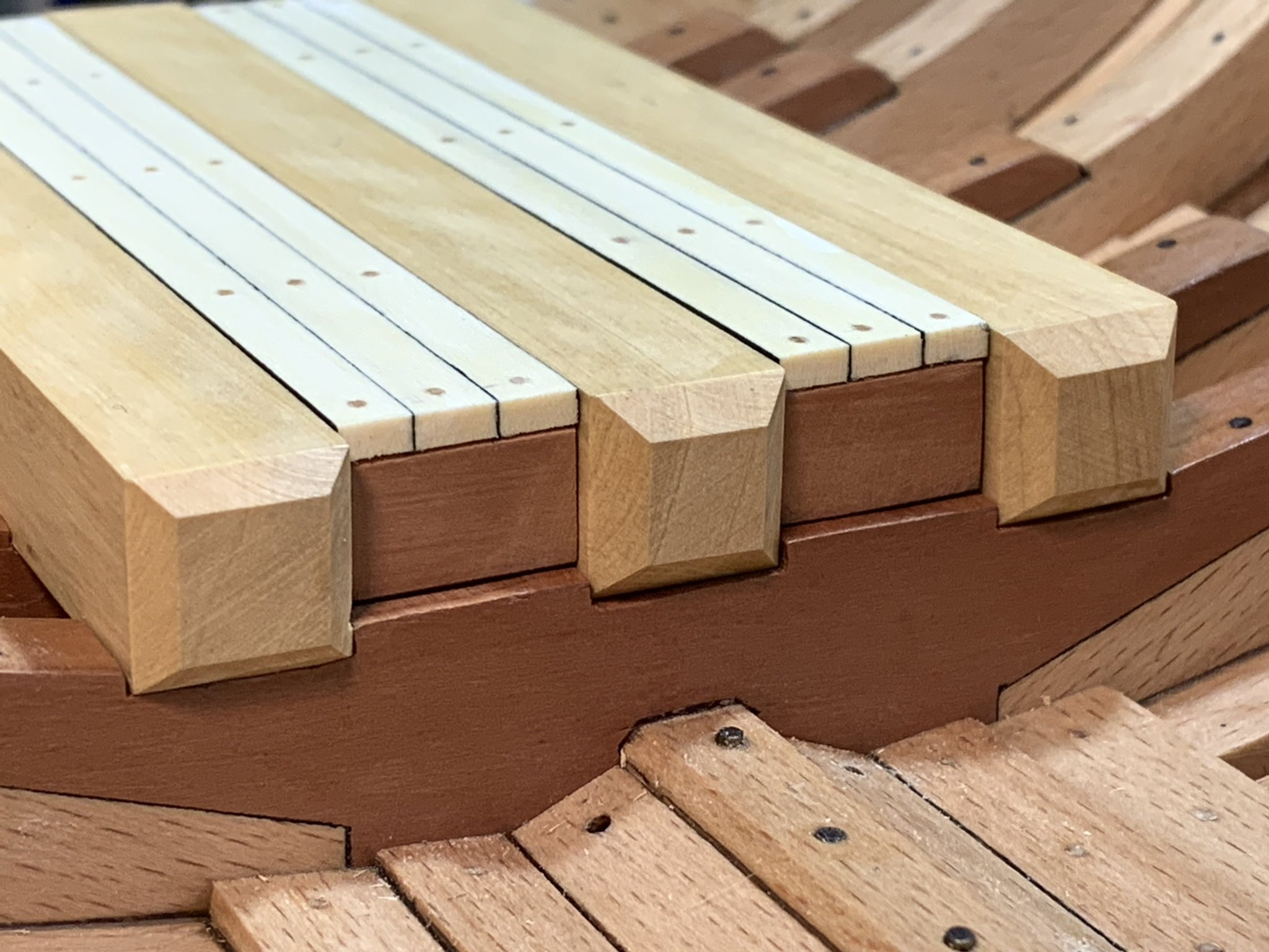
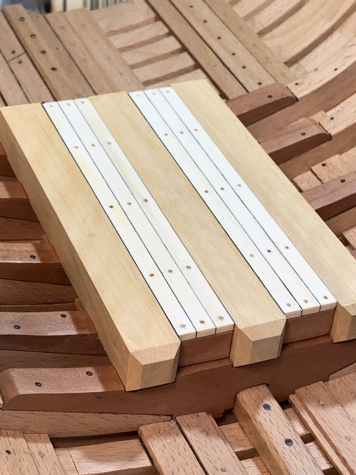
After gluing the mortar pit support beams in place I began work on the mortar pit itself. The first parts to make were the boundary timbers that define the outboard boundary of the pit deck. These are swiss pear timbers with a rabbet ploughed into them to accept the secondary planking layer.
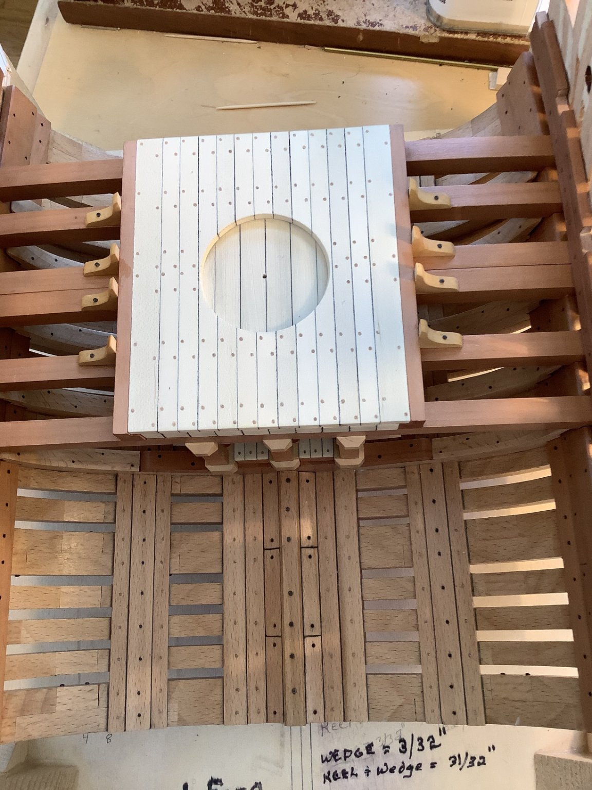
There a two layers of planking. The primary or lower layer is thick: about 9 scale inches. The secondary layer, which lays on top, is thinner and has a recess cut in it for the rotating platform the mortar sits on.
Holly can get mold growth which can stain it a bluish gray color if there is too long a delay between cutting the logs and kiln drying. I had a piece with that stain in it. Rather than chucking into the fire wood pile, I used it for the lower planking, since only the ends of the planks can be seen and they don't show the staining. The photos show the lower or primary mortar pit planking and the boundary timbers. Note the discoloration of the holly.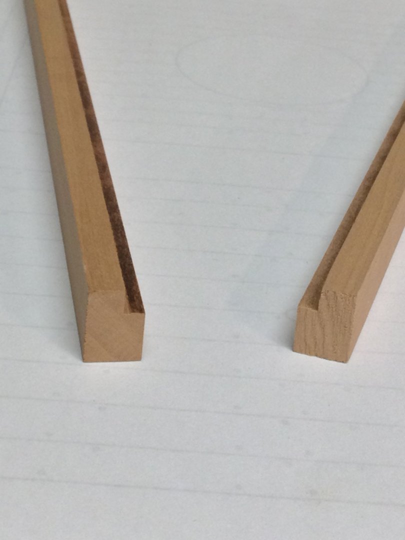
-
-
Thanks, Jean-Paul!
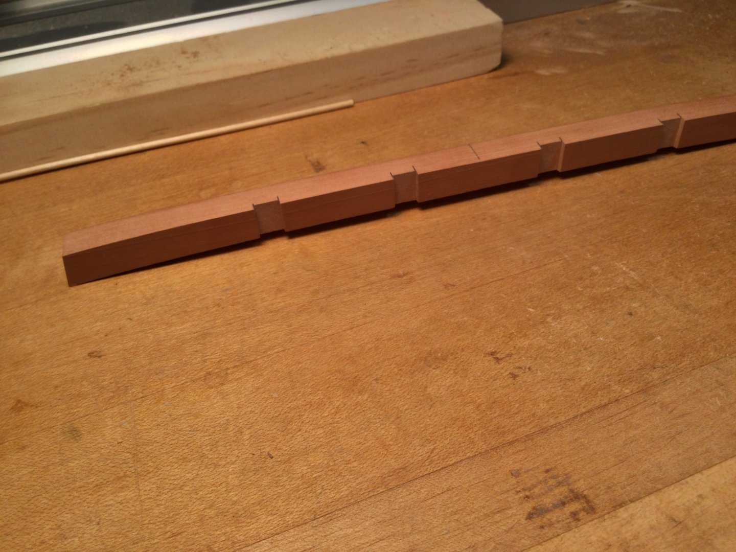
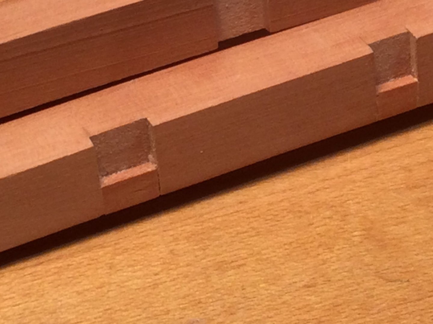
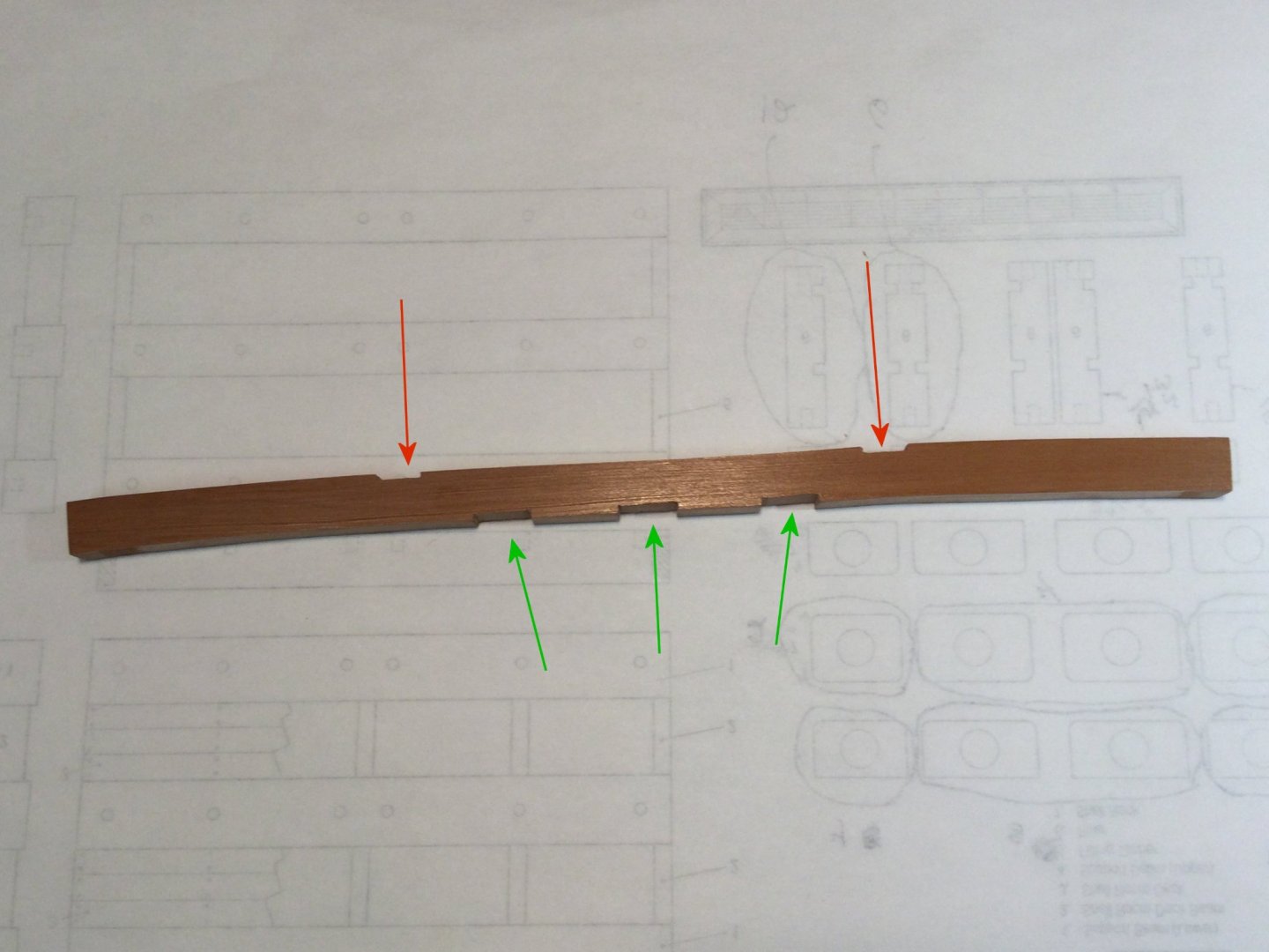
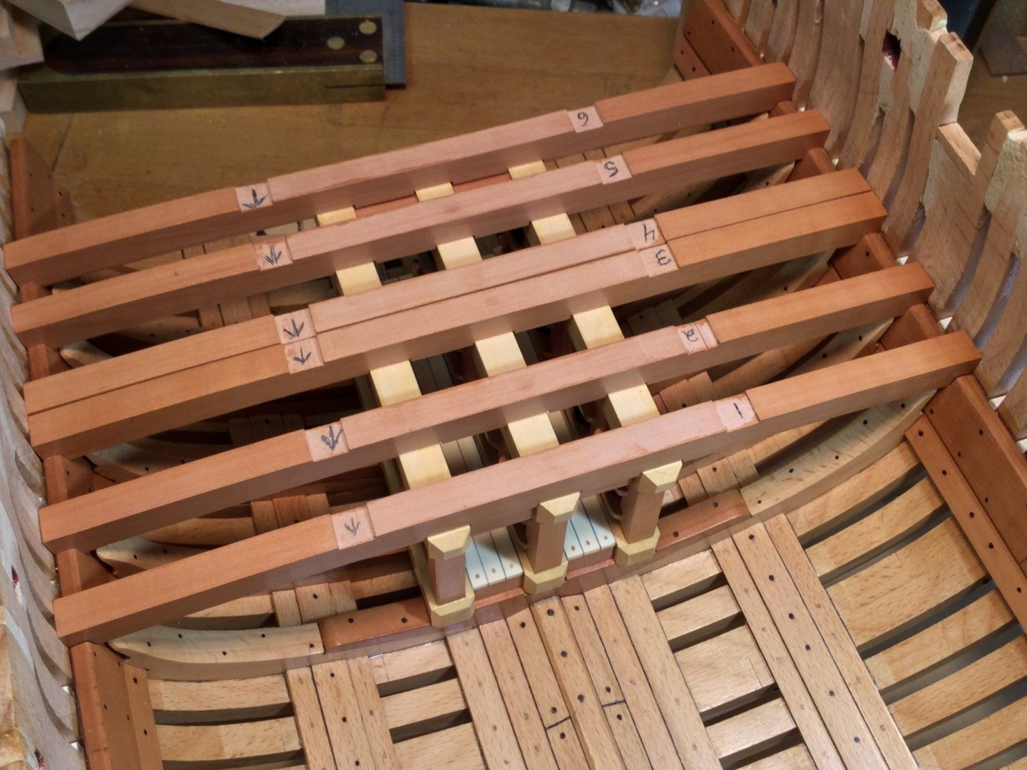
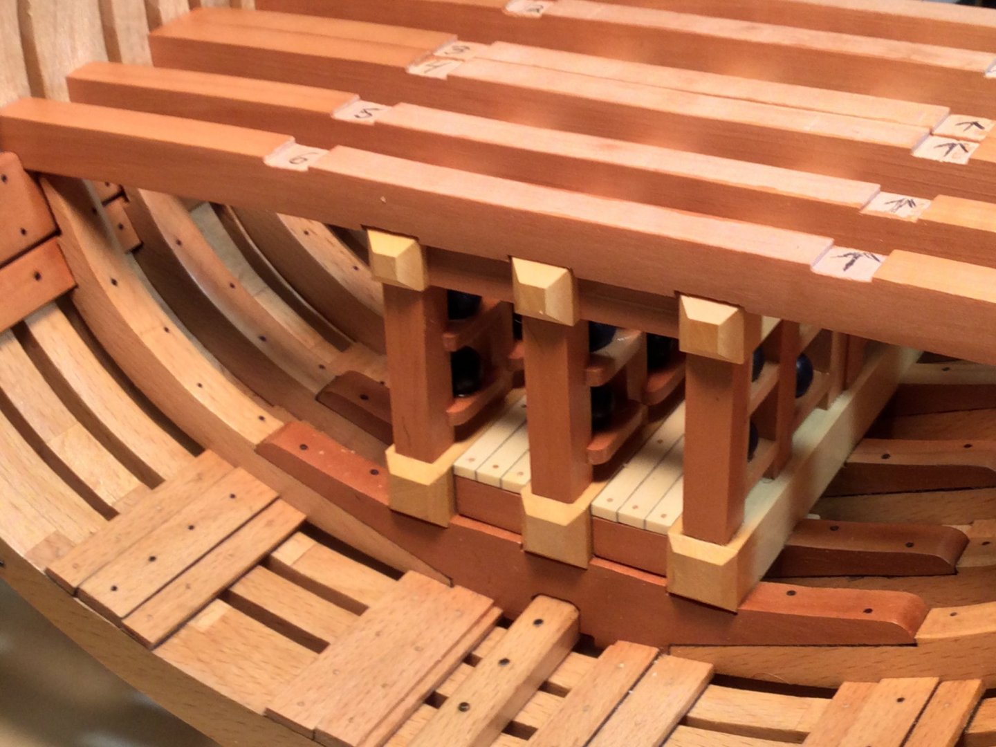
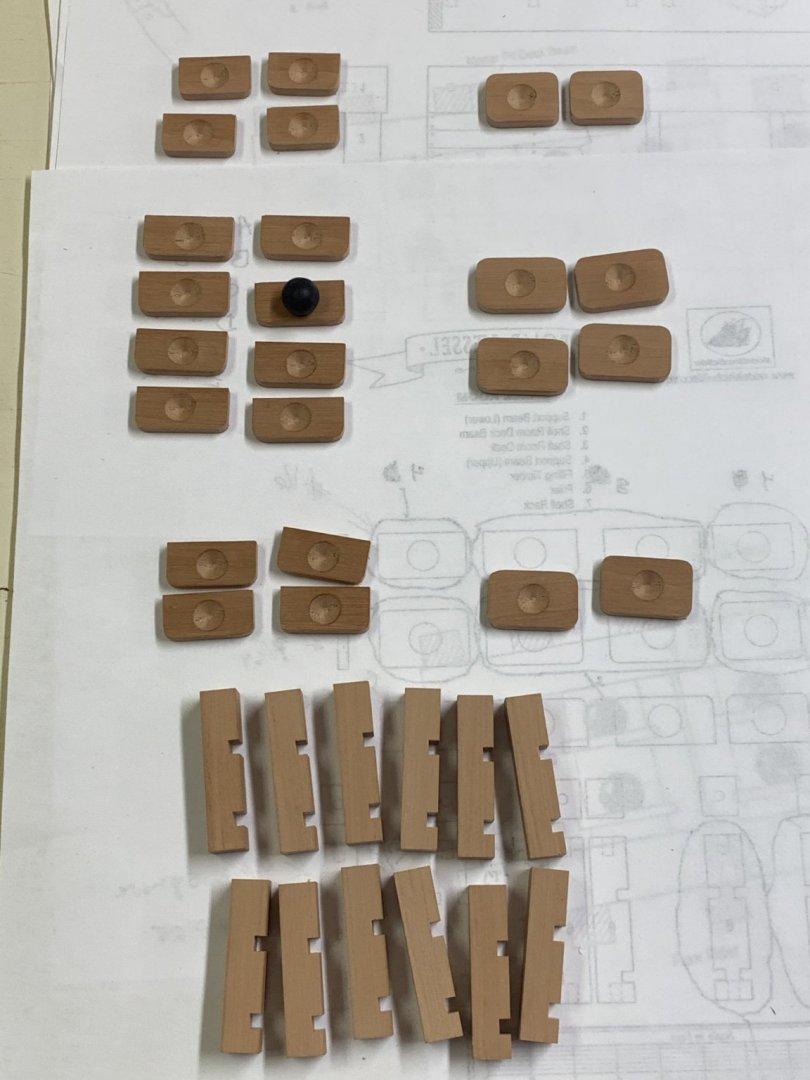
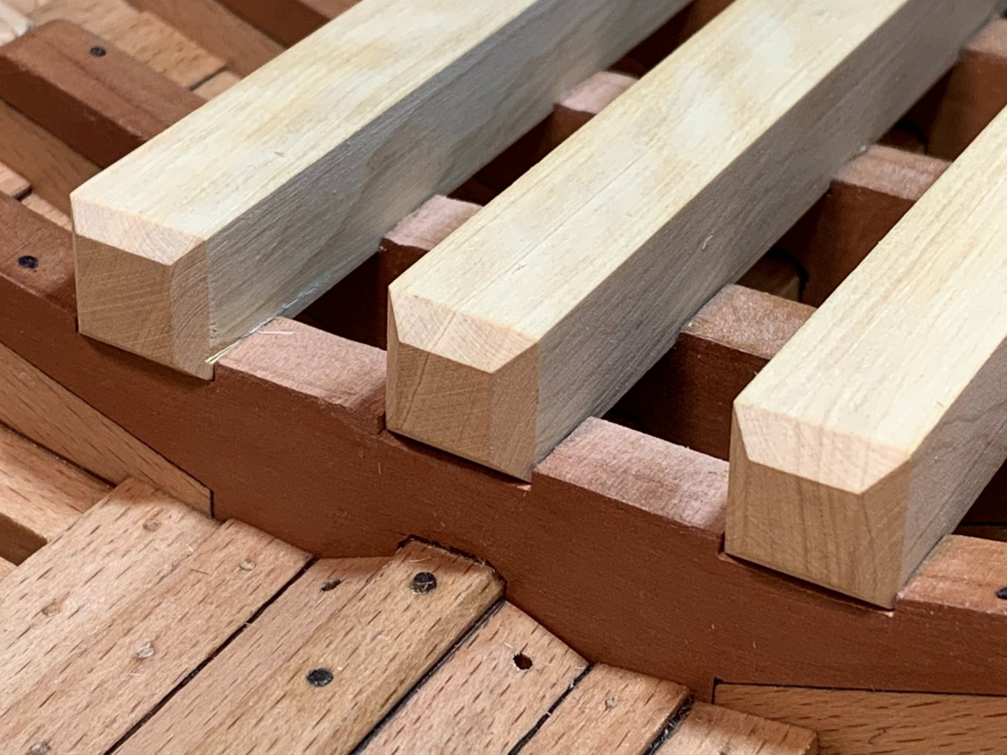
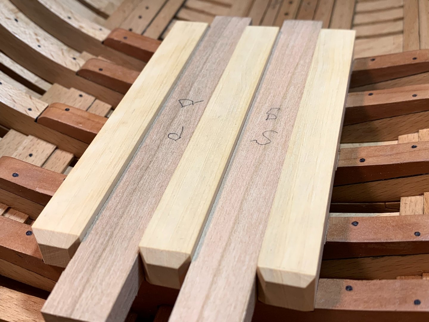
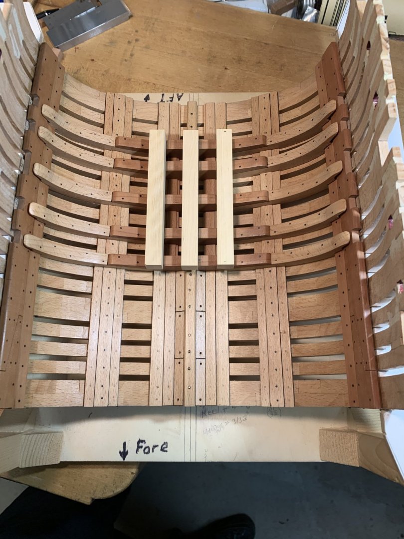
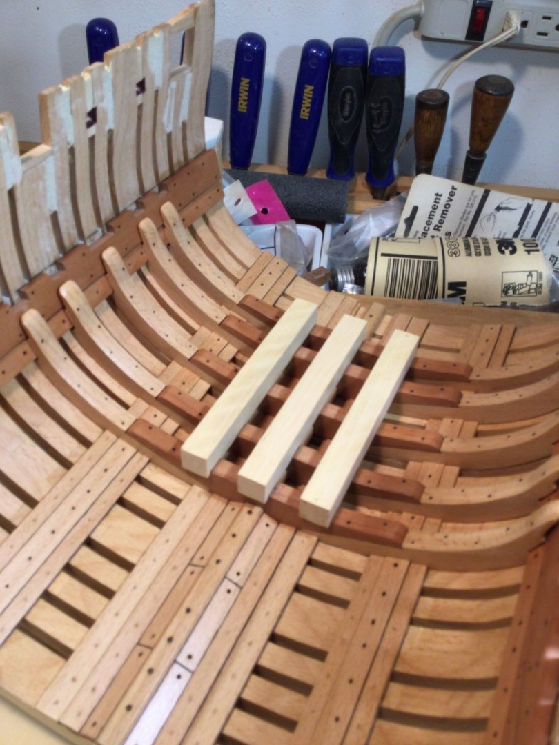
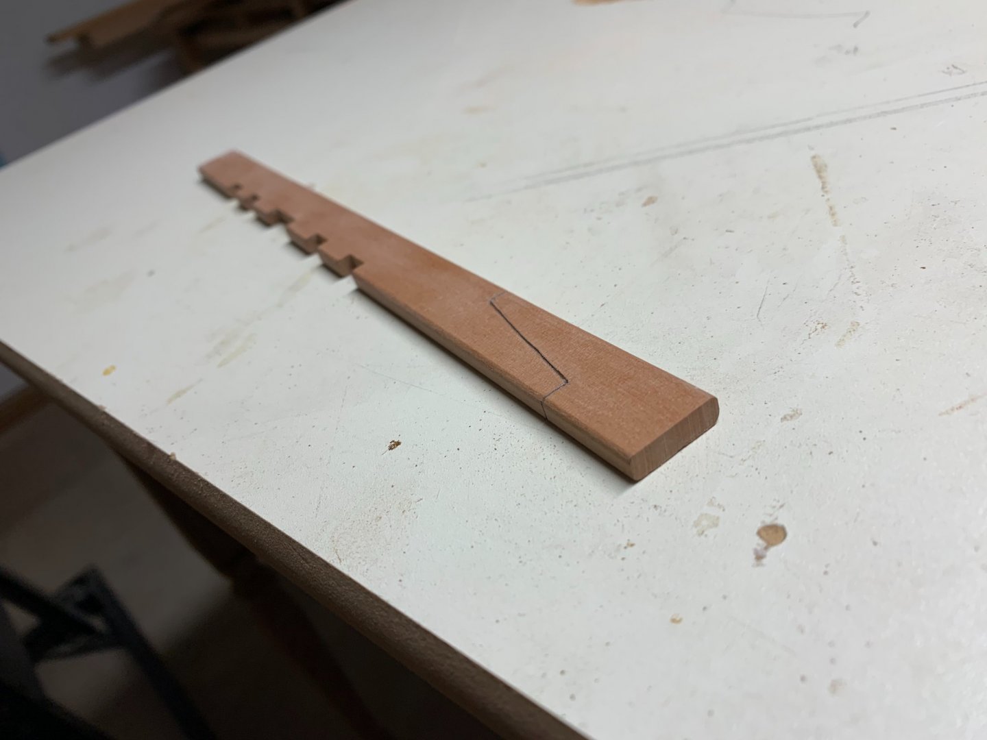
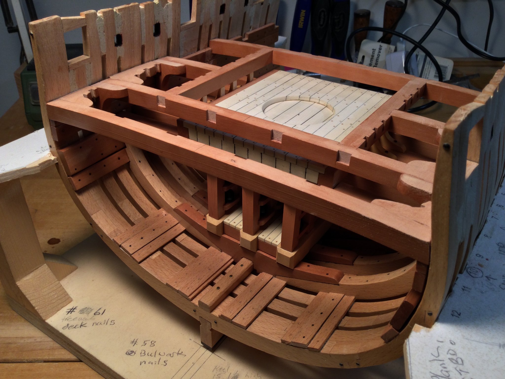
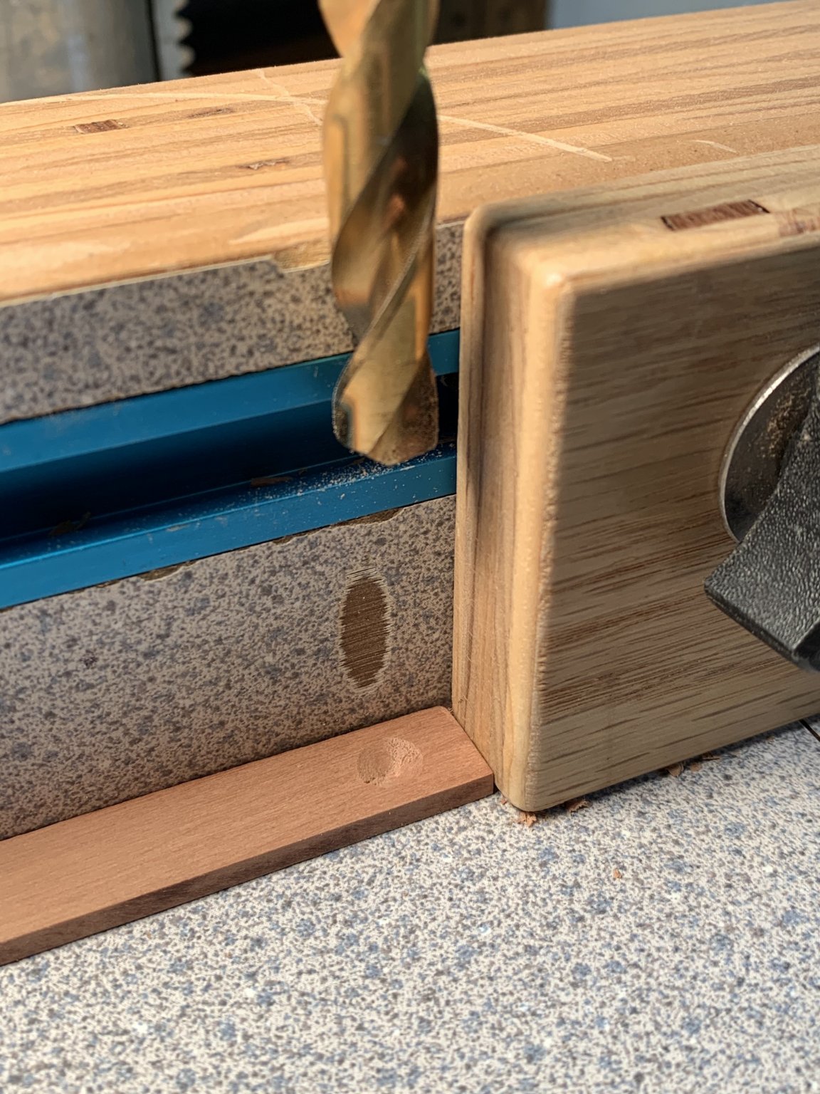
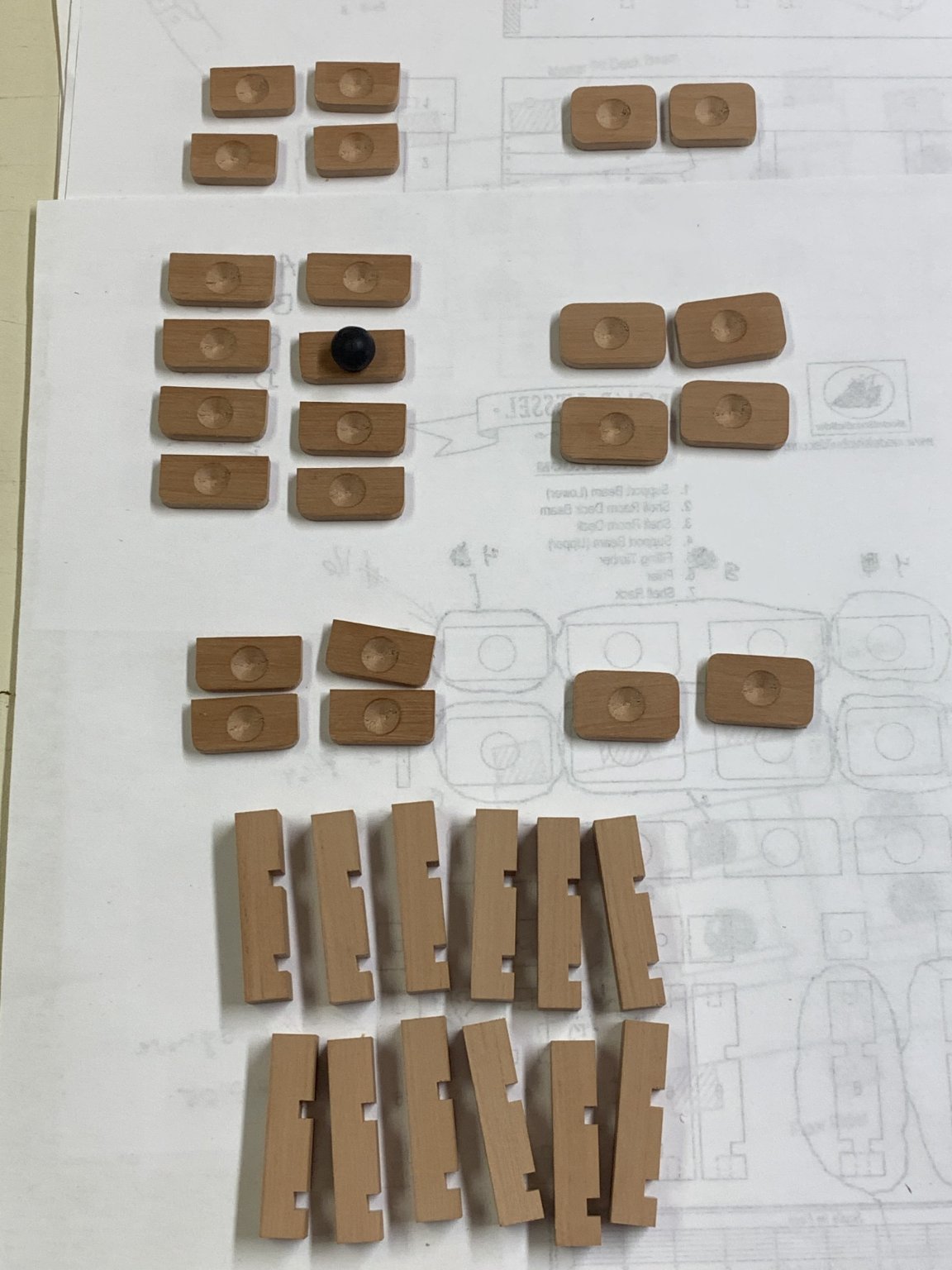
The next step is to cut out the mortar pit beams. These support the pit deck itself, and in turn, rest on the upper support beams of the shell room. There are notches (really shallow dadoes) for both on each beam.
I milled up some 3/8" thick swiss pear and glued the beam templates to the wood with rubber cement. They were then cut out using the scroll saw. The mortar pit boundary timbers fit in the dadoes on the upper surface of each beam (red arrows). It's important that these line up exactly so I cut the beams a little long and snuck up on the final length using the disk sander. There should be no side-to-side play in the beams when fitted properly. Then I cut the dadoes on the under surfaces of the beams (green arrows) after marking each one individually so the fit on the upper support beams is precise. The beams have poly but are not yet glued in place.

- Canute, garyshipwright, Matt D and 11 others
-
14
-
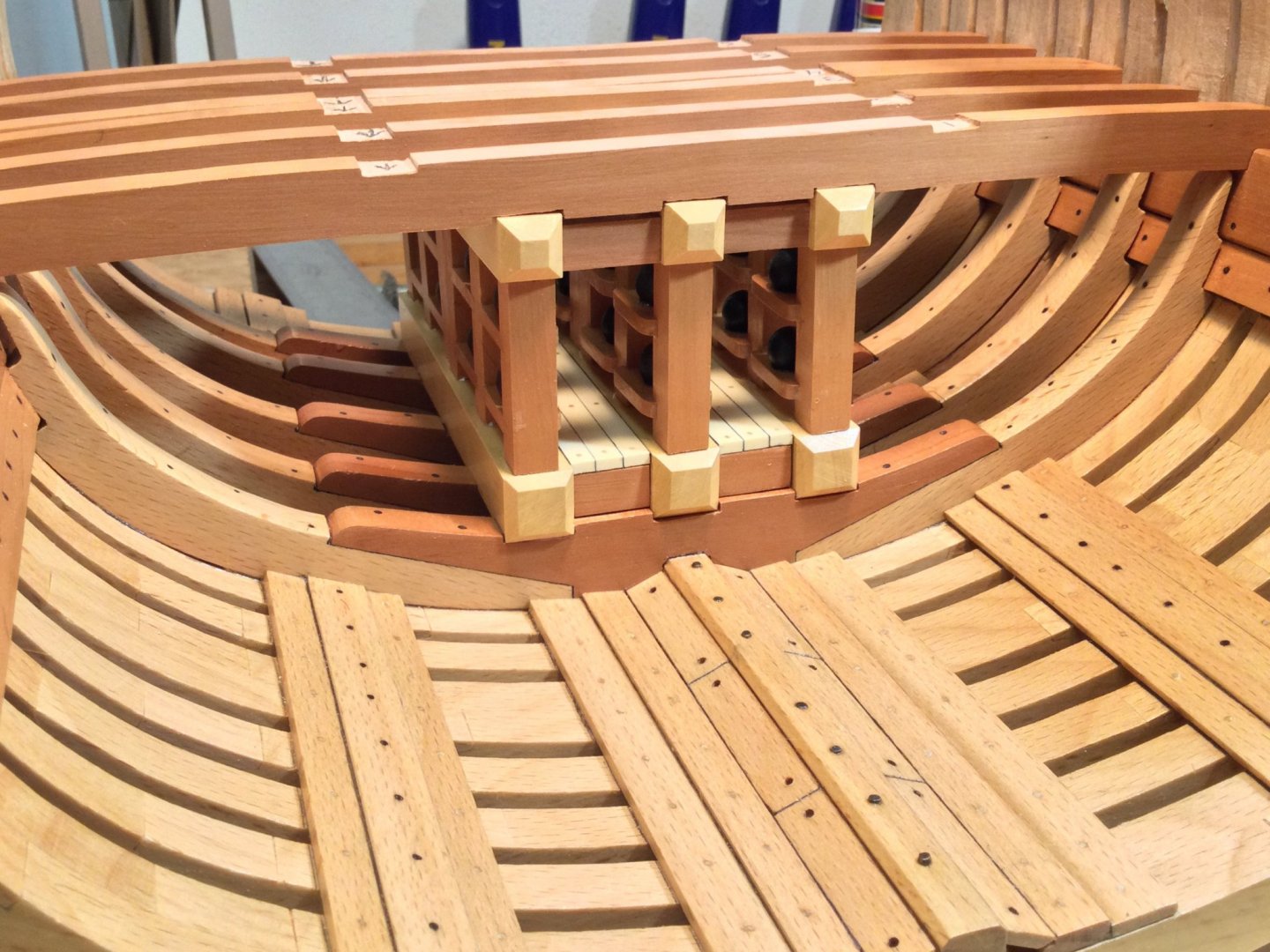
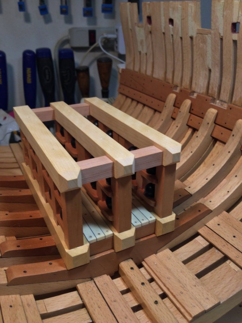
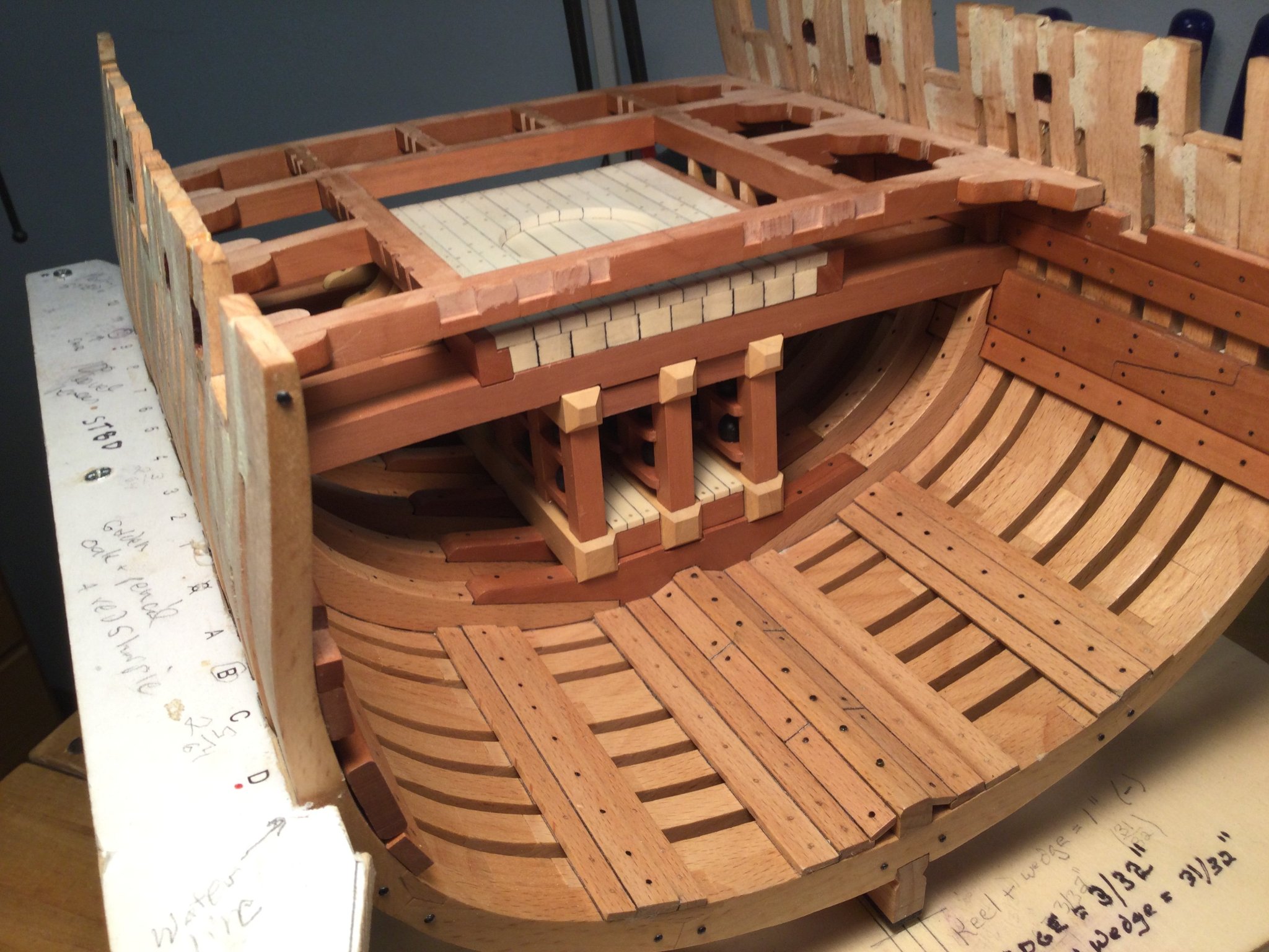
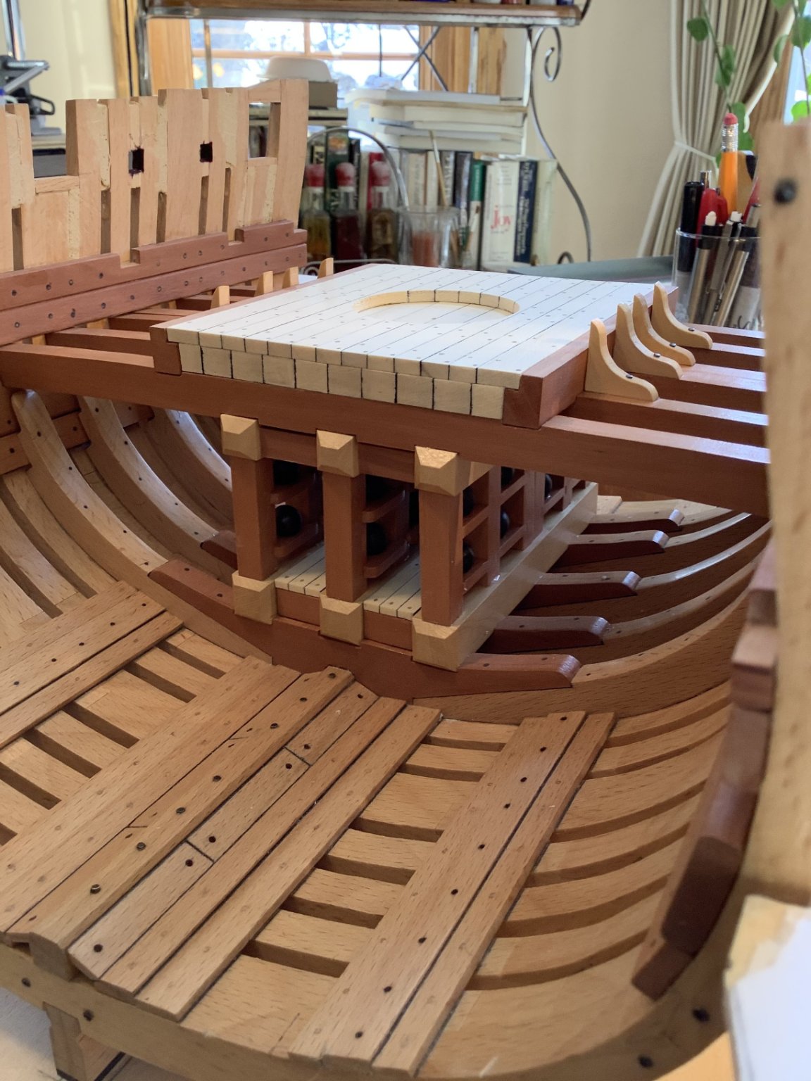
Work on the shell room continues. I made the upper support beams out of boxwood and the blocking timbers between them of pear. They're glued into place, but not poly'ed yet. Once that's done, I will individually fit each of the 6 mortar pit beams into their notches on the clamps.
- Matt D, Captain Poison, bruce d and 15 others
-
18
-
Thanks, Grant!
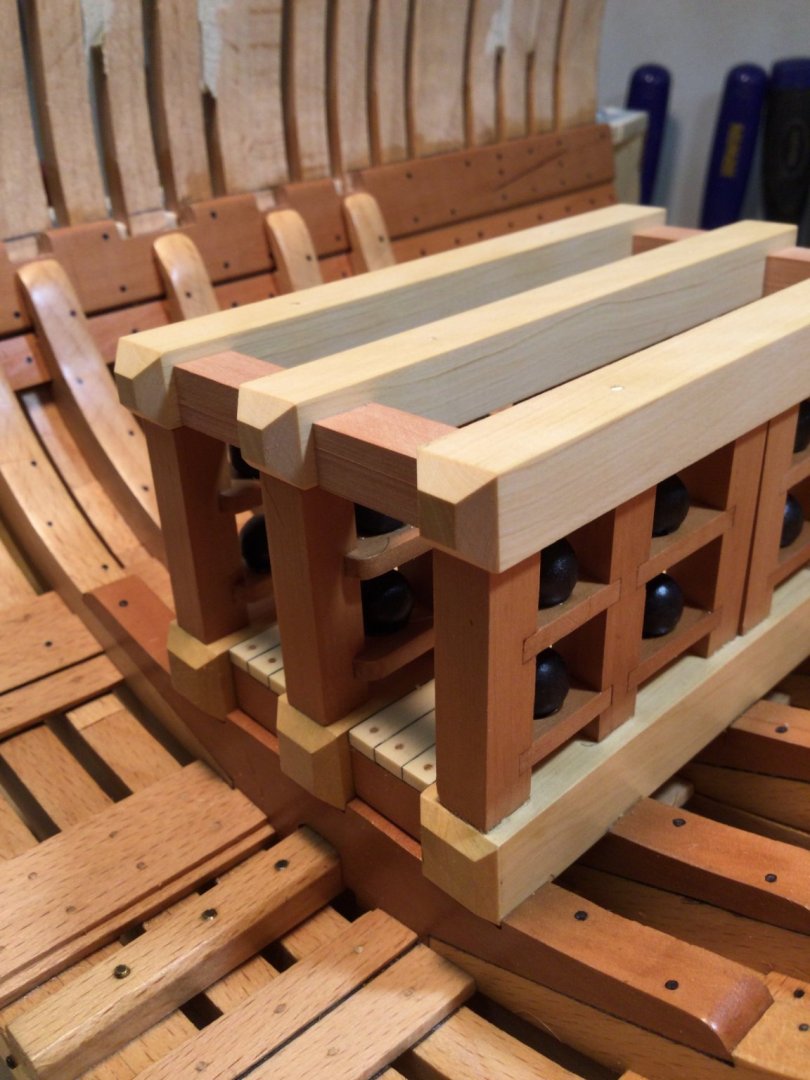
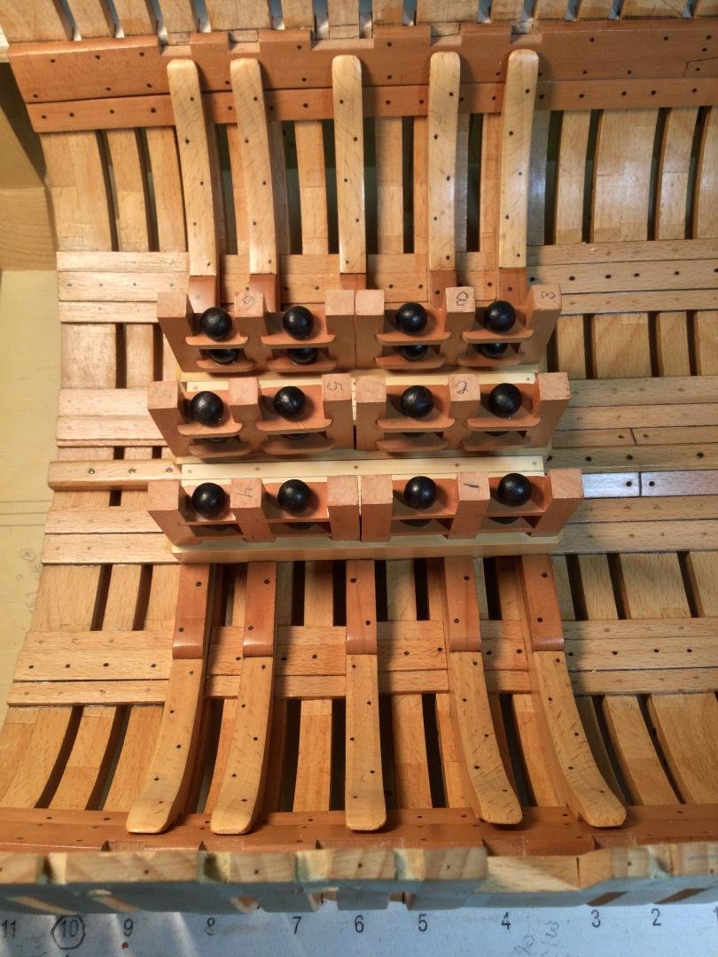
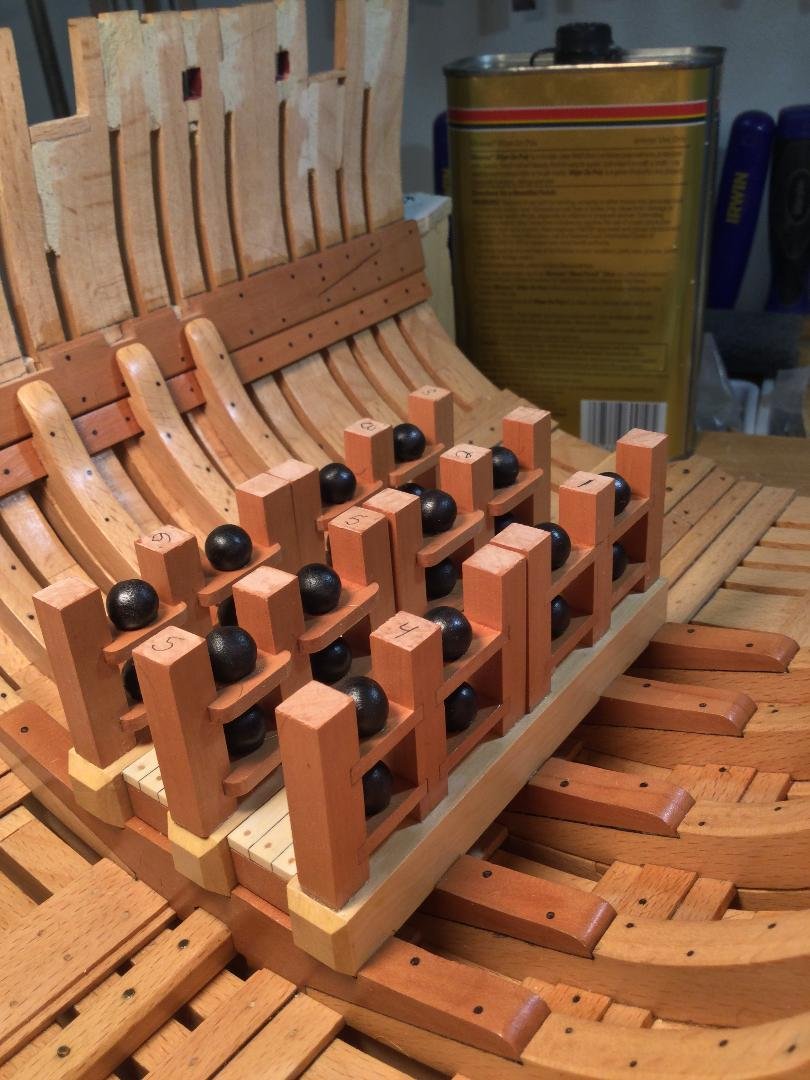
I glued the six shell racks to the lower support beams. The placement needs to be precise because two more layers of structure sit on top of the shell racks before the mortar pit floor. The plans call for the racks to be pinned in place. I thought this would be too difficult to do precisely so I used a couple of home made jigs to align the shell racks while the epoxy I used dried. They're not going anywhere!
- bruce d, mtaylor, Edwardkenway and 12 others
-
15
-
-
-
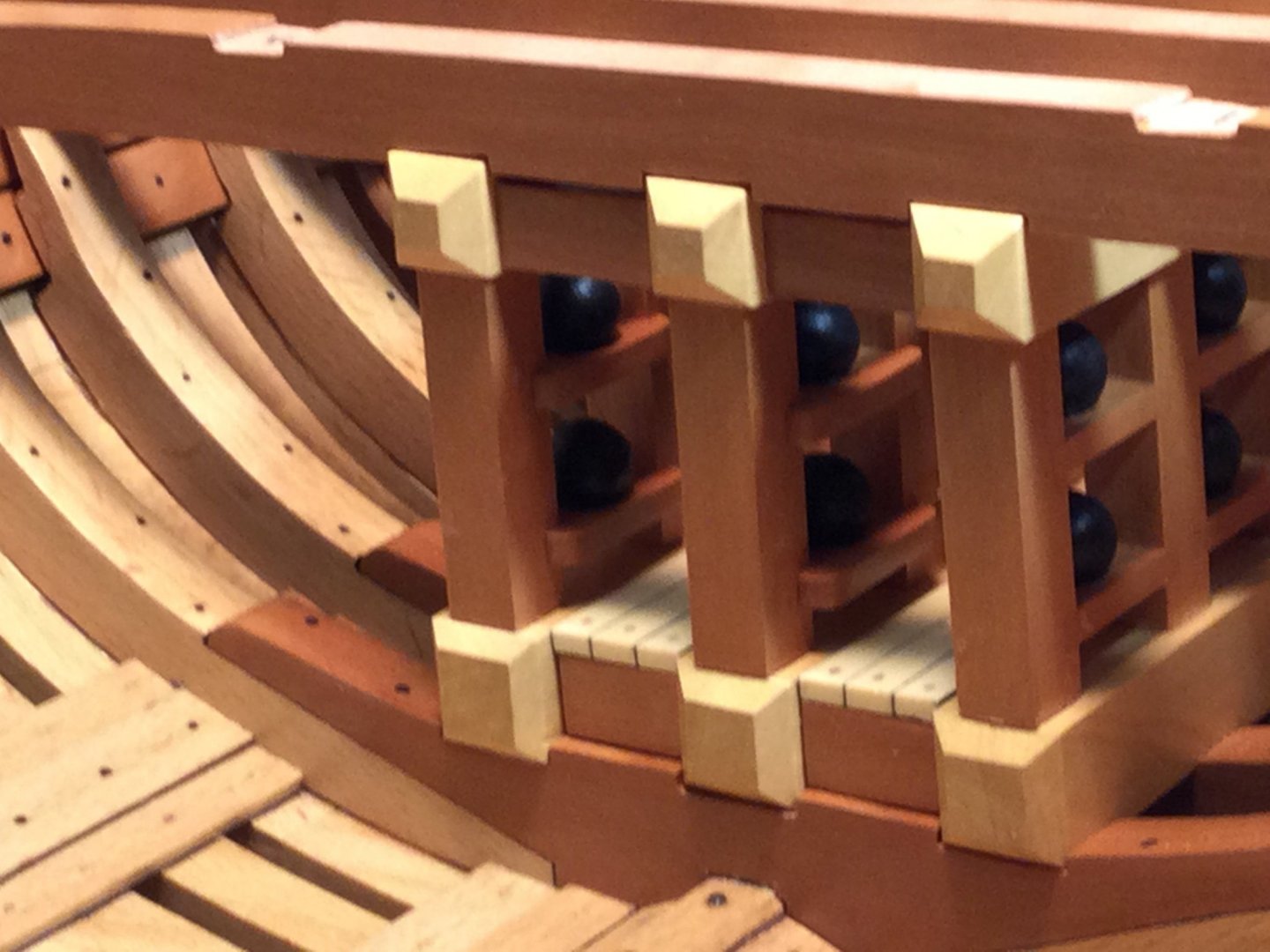
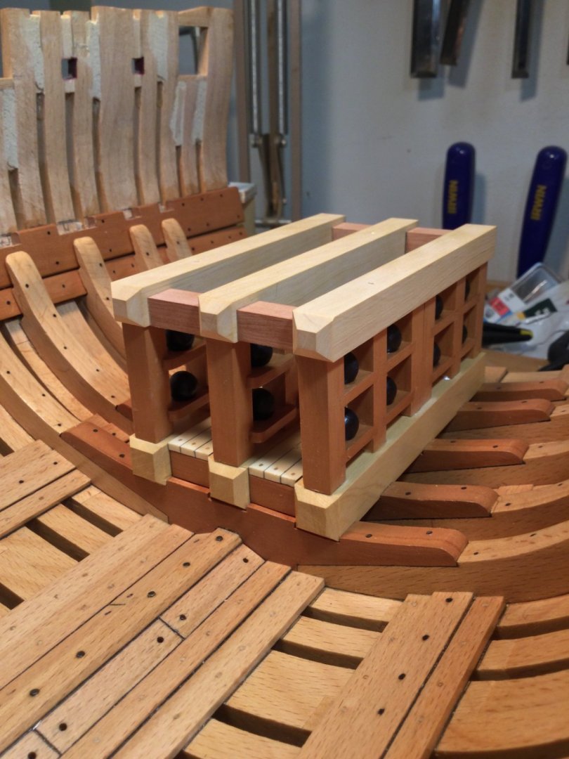
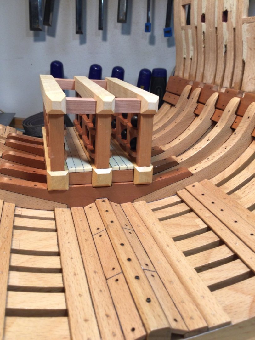
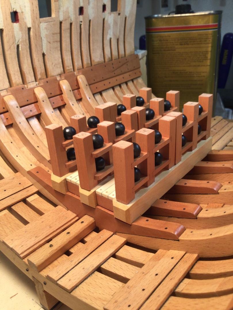
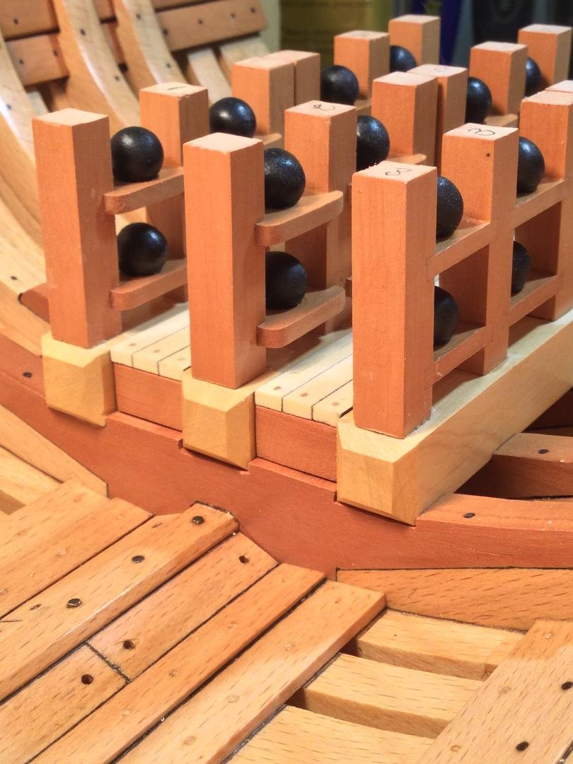
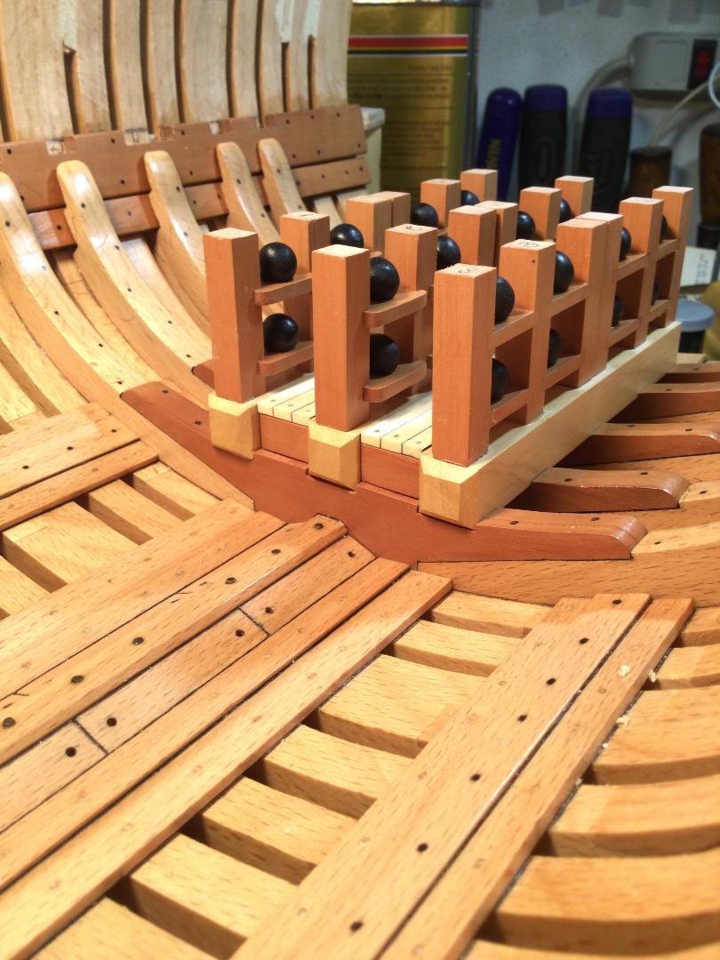
Thanks, Jean-Paul!
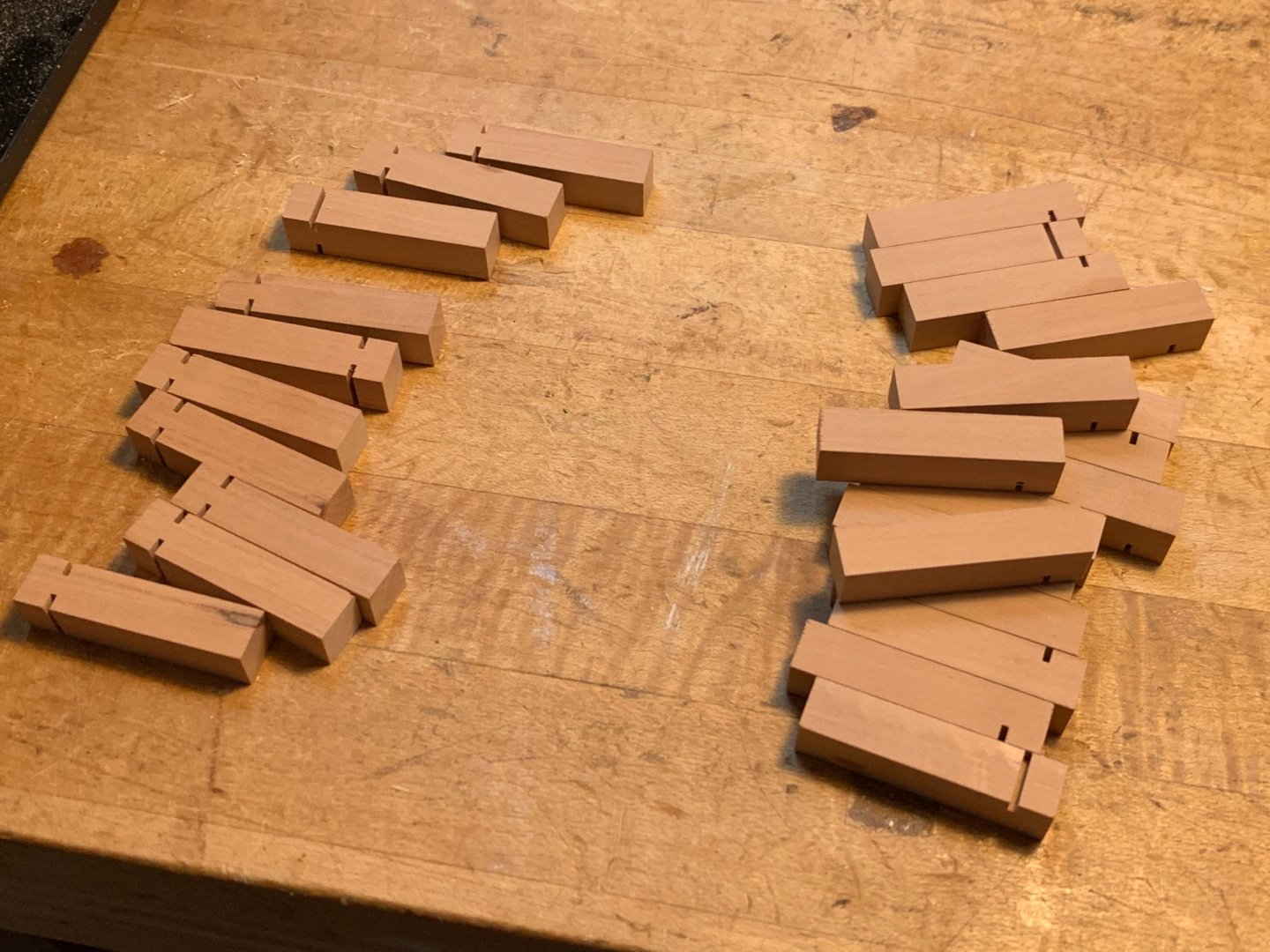
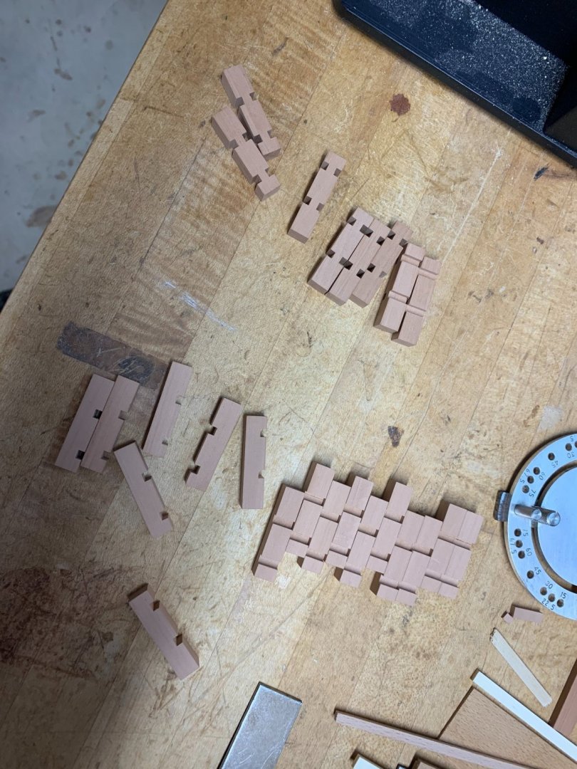
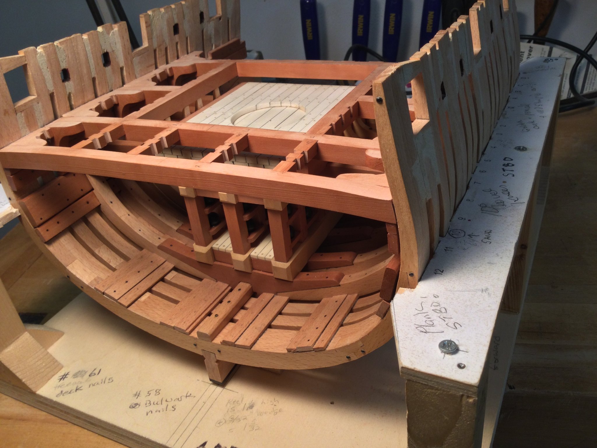
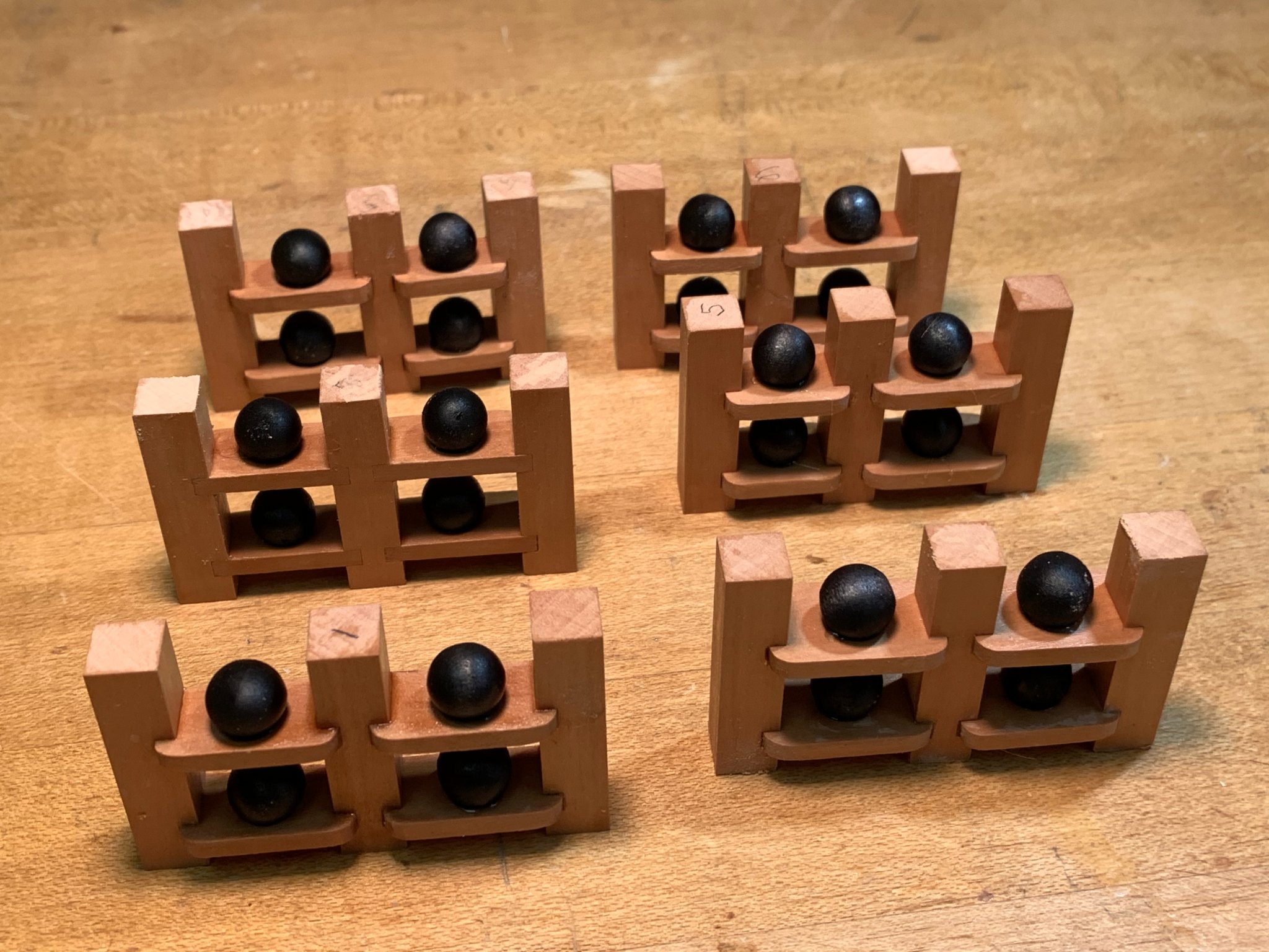
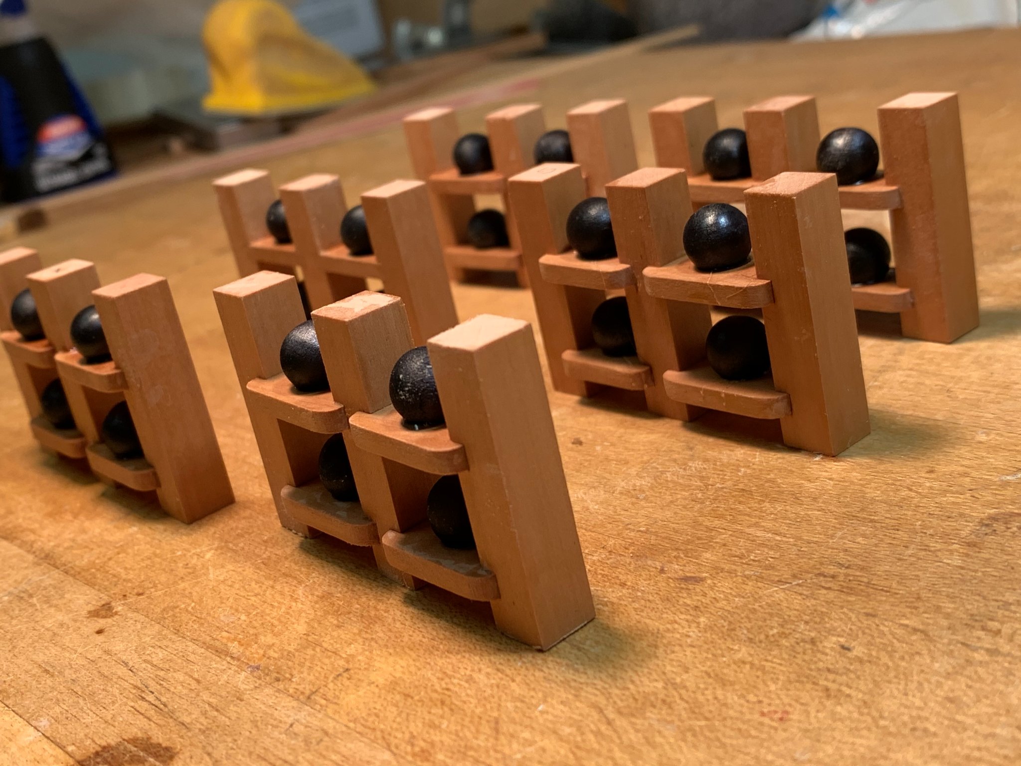
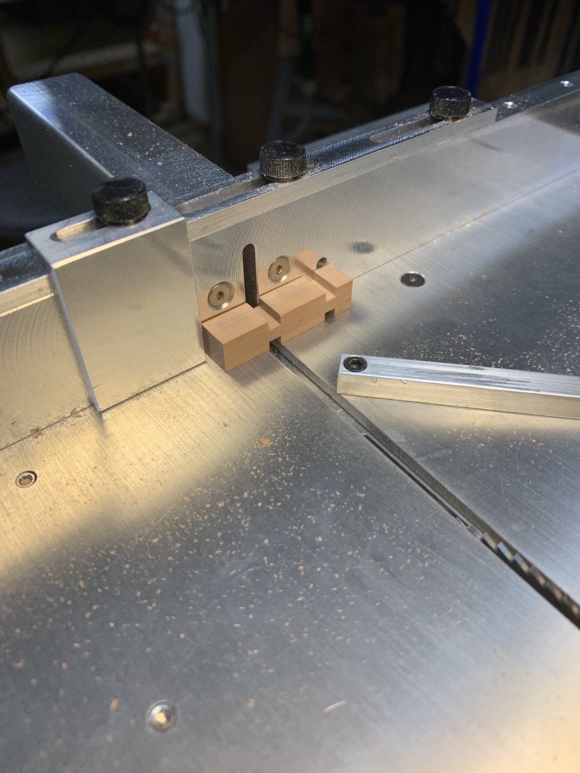
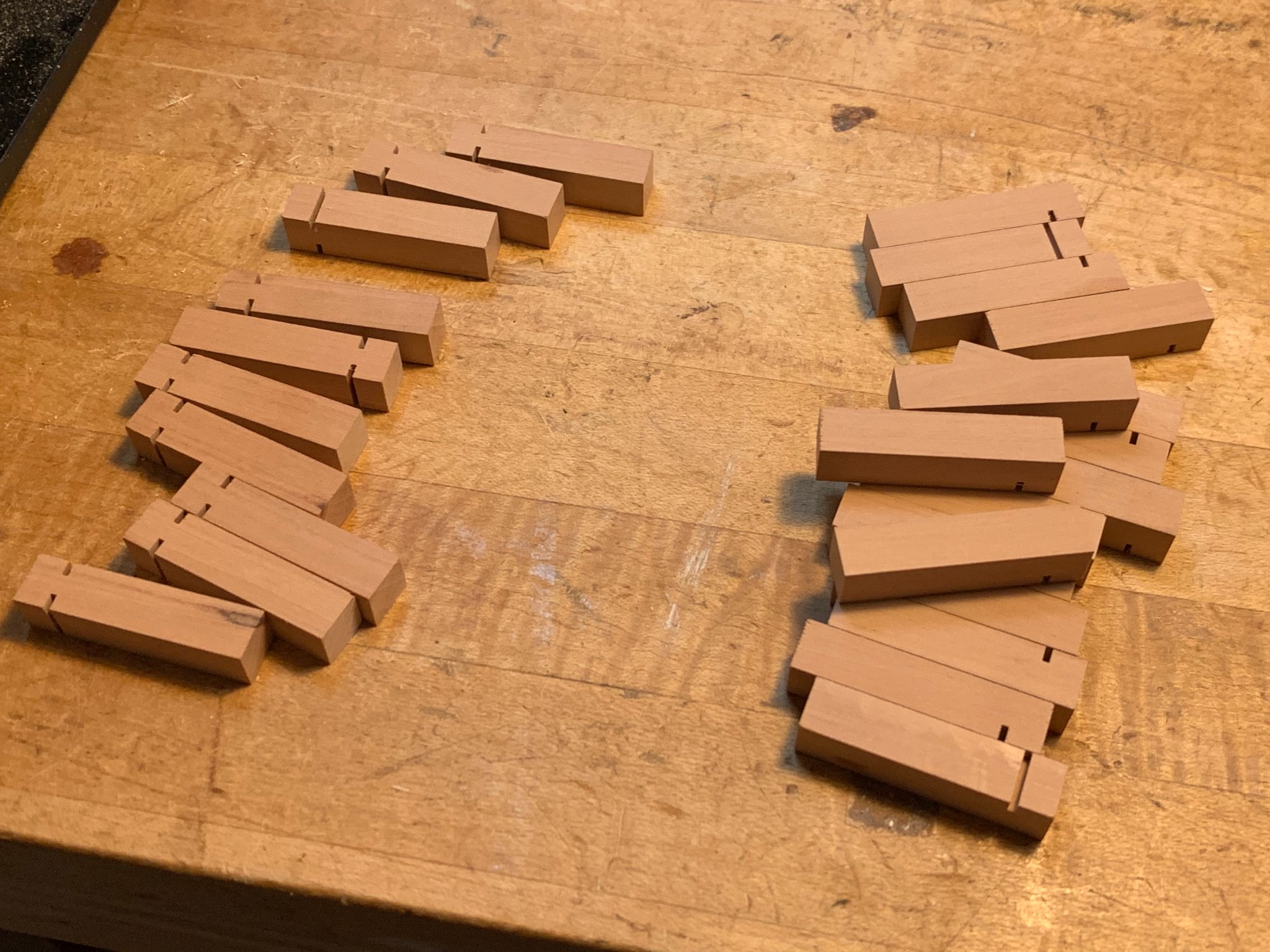
The shell room is made up of 3 rows of 6 pillars which support 24 shelves. Each shelf has a hollow into which the mortar shells fit. The pillars are cut from square swiss pear stock. I used my Byrnes saw with the sliding table to cut the pillars and the notches for the shelves. The sliding table is deadly accurate, and each pillar is EXACTLY as long as as the next, with the shelf slots perfectly aligned. The tool is amazing!
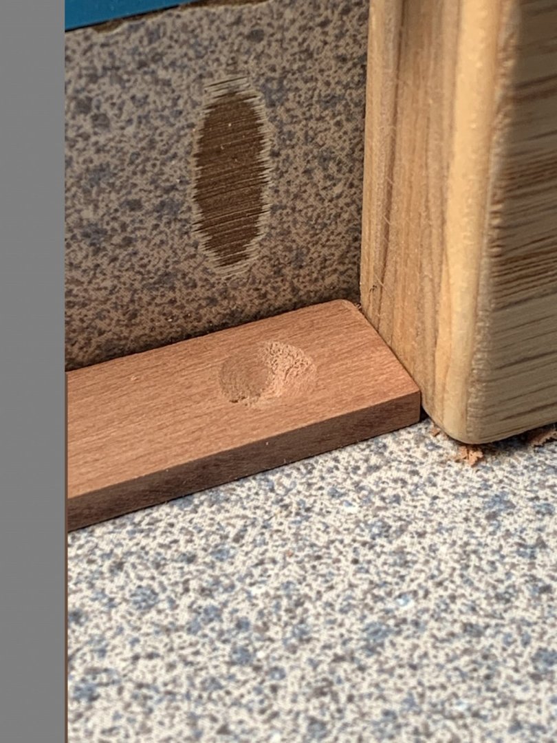
The shelves were cut from swiss pear also. To form the depressions that hold the shells, I used a 3/8" twist drill on my drill press. I set the fence and the stop so each depression was in a consistent location on the shelves.


-
I finished the decking (holly) and glued it into place. One coat of poly applied.

- Canute, MEDDO, dantist905 and 11 others
-
14
-
Thanks for the "likes", guys!
I began construction of the shell room with the lower support beams. I cut them to overhang the floor riders by 3/32" on each end and then chamfered both ends of each for visual interest. These were glued in place. Next I cut out two filler pieces to fit between the support beams. These are 3/32" thinner than the thickness of the support beams so when the decking is installed, there will be a flush, flat surface. Next is to trim and finish the filler pieces.
- Edwardkenway, rafine, Canute and 8 others
-
11
-
I finished all the planking in the hold and installed both upper and lower mortar pit clamps. Everything was given a first coat of poly. I also cut out the shell room lower support beams. They are boxwood. Swiss pear and holly will be used to build the shell room.


-
34 minutes ago, Larry Cowden said:
Was there a reason you did not tree nail the athwartship planking?
Not really! I just liked the look. Thanks for looking in!
-
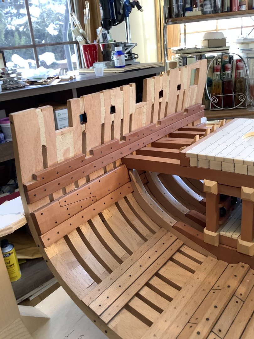
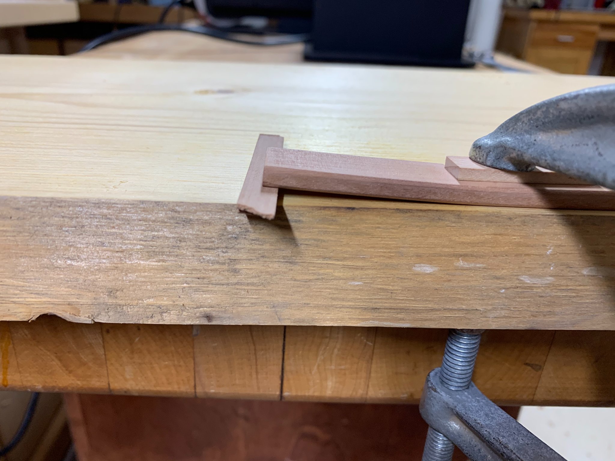
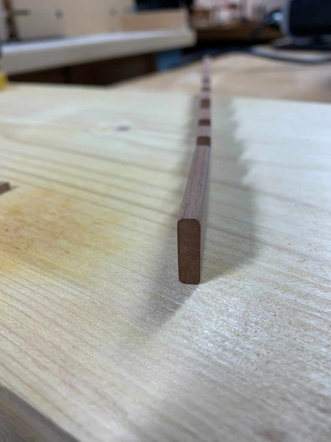
The next task was to prepare the upper mortar pit clamps for installation. These were heavy timbers that bore a lot of the brunt of the mortar's recoil force The clamps were 24" tall and 7" thick (3/4" X 7/32"). There are 5 mortises cut into the clamp to seat the mortar pit beams. For the most part, the clamps are straight. But they do curve inward fairly conspicuously over the last 3 frames or so. I needed to figure out how to bend a piece of swiss pear that was 3/4" wide X 7/32" thick. The answer was easier than I thought. I simply clamped the clamps to a piece of wood with the inwardly bending end raised up a little on a scarp of wood. Two or three minutes with a heat gun (careful not to burn the wood) and the clamps were bent enough to slip in place easily. Now on to treenail and bolts!


-
-
Thanks Grant!
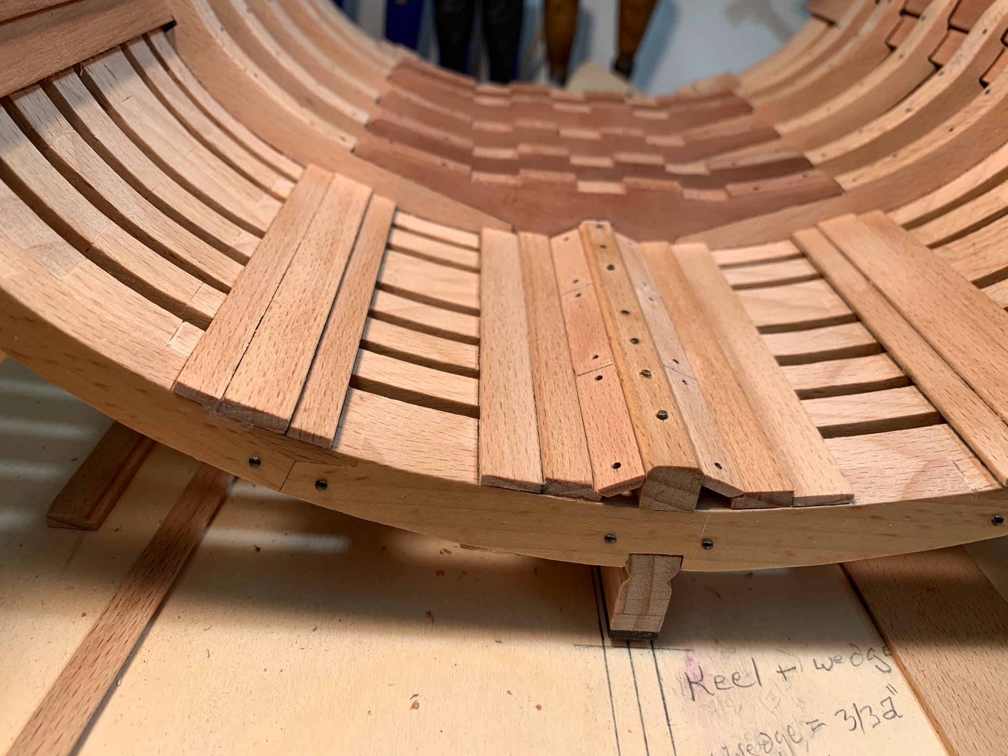
I finished the planking in the hold, including the limber strakes, floorwaling and thick stuff. The mortar pit clamps are just sitting in place. The next task is to "dress up" the planking. I'm planning black bolts for the thick stuff and clamps and birch treenails for all the other planking. I'll also simulate a scarf in the upper mortar pit clamp.
The limber boards are just over 3 scale feet long with finger holes drilled in each end. They should be manageable by a single seaman himself.


- VTHokiEE, ferarr, Edwardkenway and 9 others
-
12


Granado 1742 by DocBlake - FINISHED - 1:32 Scale - Bomb Vessel Cross-Section
in - Build logs for subjects built 1501 - 1750
Posted
Thanks!
I turned a few pillars out of swiss pear to support the upper deck beams. They rest on the keelson.