


BETAQDAVE
-
Posts
5,383 -
Joined
-
Last visited
Content Type
Profiles
Forums
Gallery
Events
Posts posted by BETAQDAVE
-
-
Thanks for all the suggestions guys. I finally ended up using one of those cheap third hand device and some wood dowels for my solution. See my log on the whaling bark Wanderer for more details.
- mtaylor, thibaultron, Canute and 1 other
-
 4
4
-
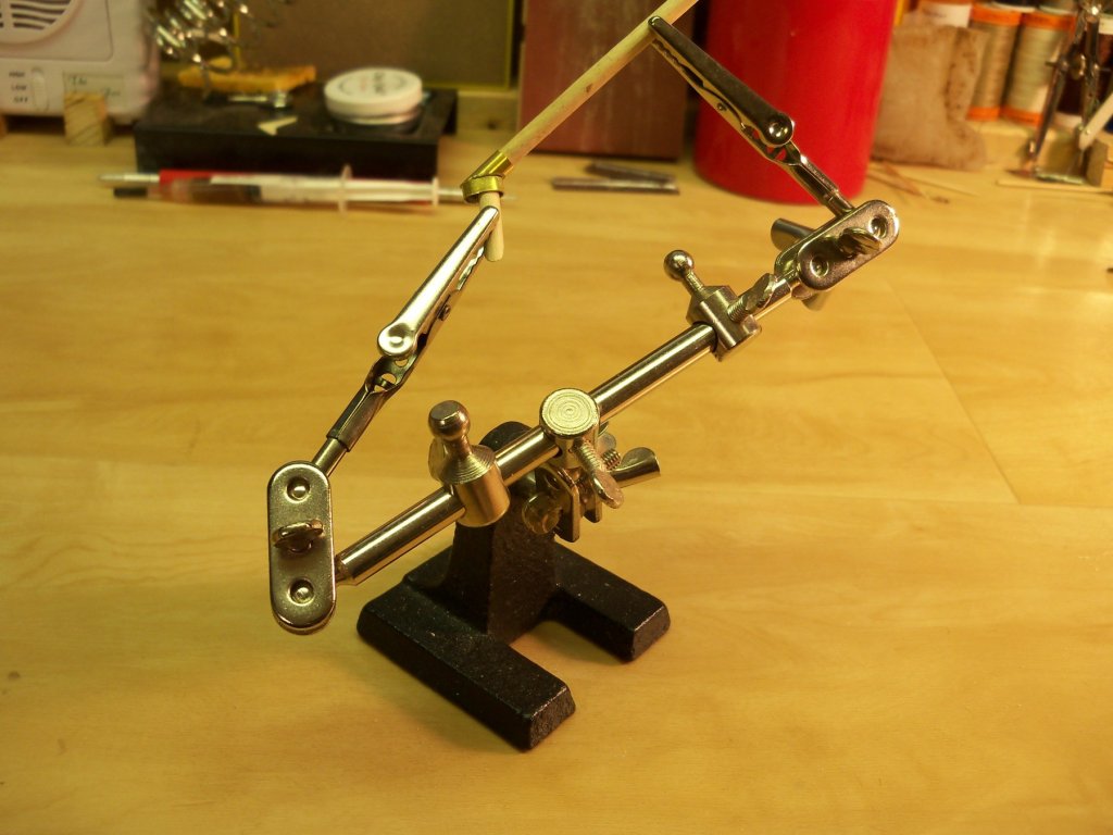
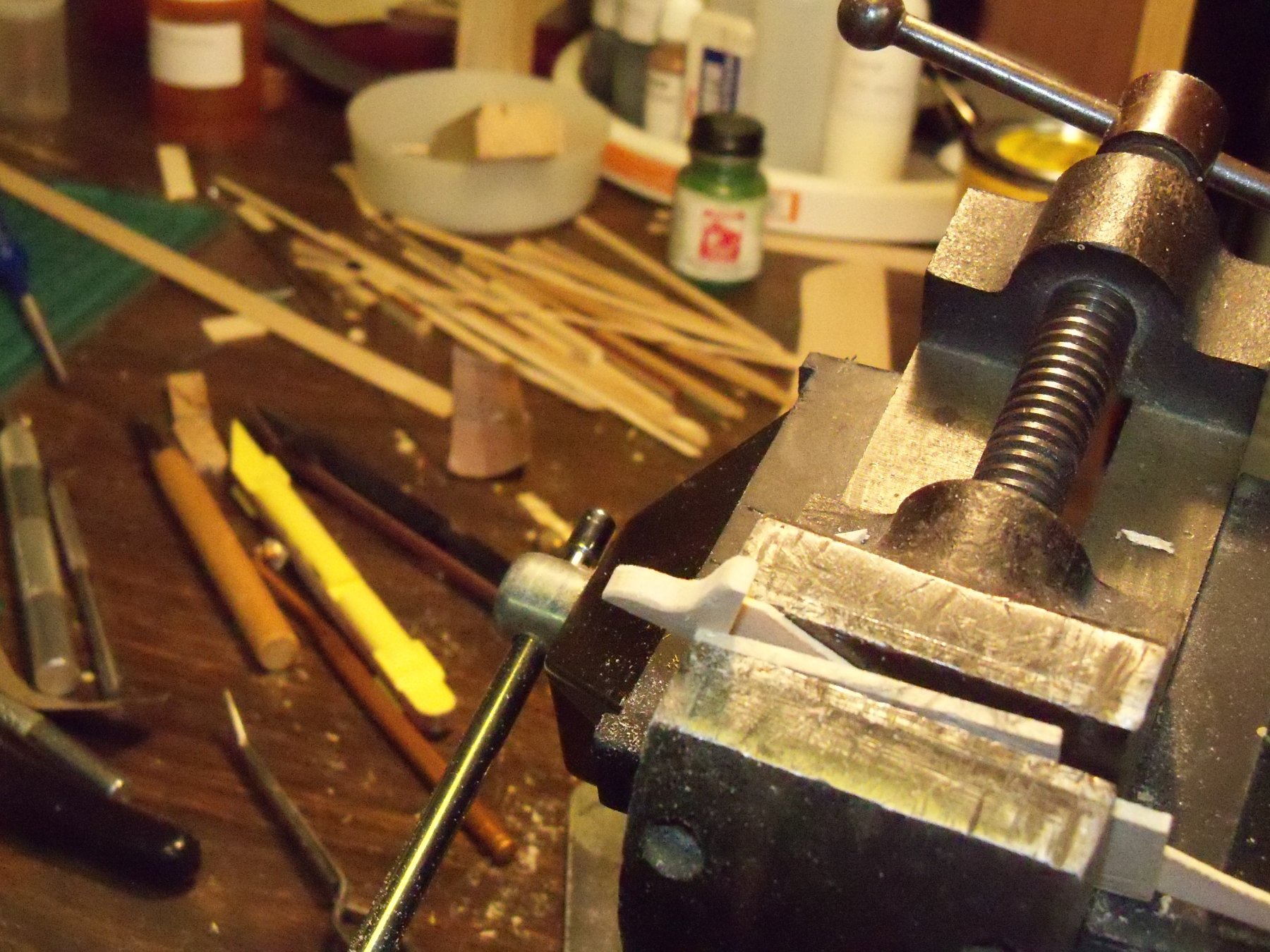
After some time looking through MSW suggestions and build logs, I noticed that some members used wood to mount the parts in a jig. I also have a lighted third hand with magnifier that I picked up from Micro-mark that others have mentioned.
Although a bit clumsy to use as it came for this application, I just removed the magnifier and the light. I also re-positioned the second hand as shown below it made it easier to use.
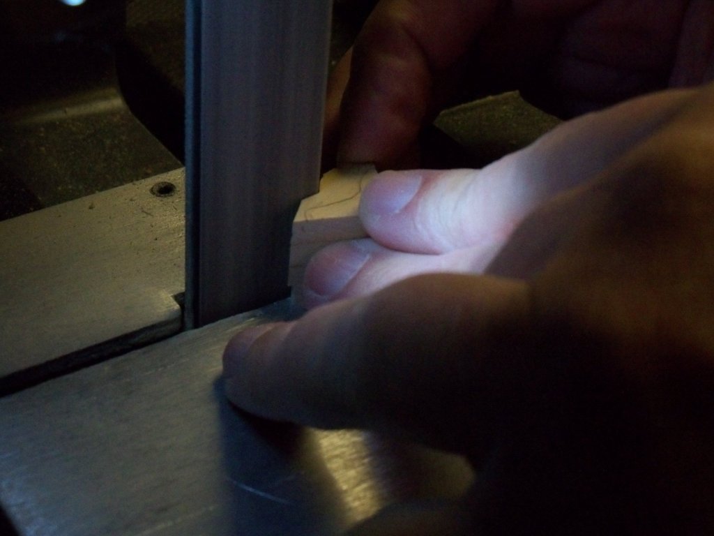
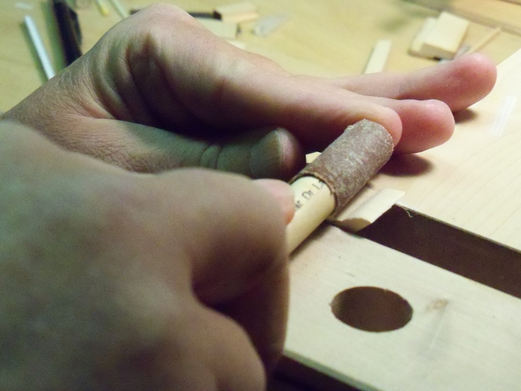
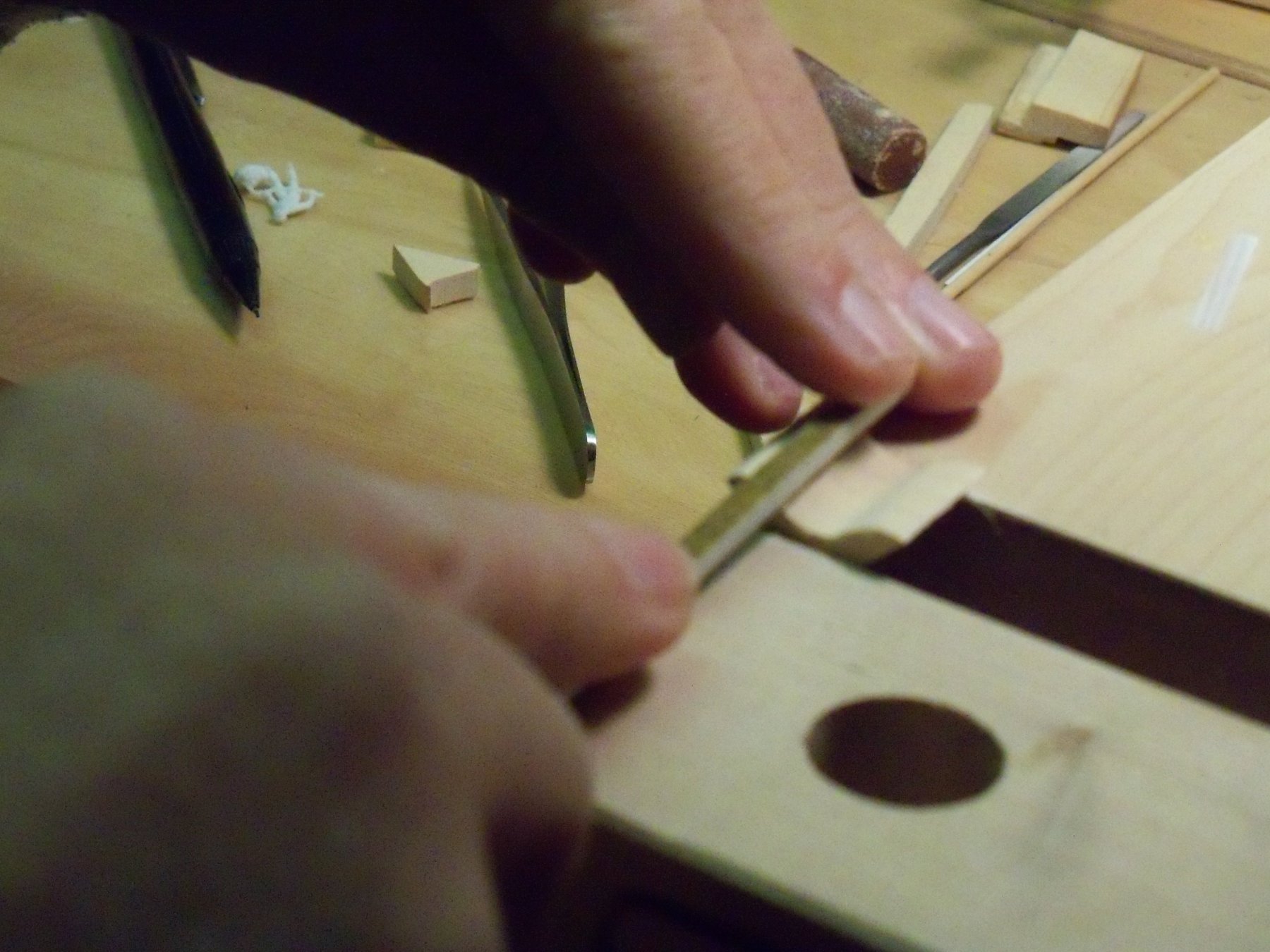
I stuck the two parts on the ends of some 5/16” wood dowels. Using the dowels as handles, I sanded the mating edges of the tubing, and lightly dipped the angled tube in some flux. Then I clamped the pieces of doweling in the two helping hands and maneuvered the parts until they were properly mated as shown in the close up here.
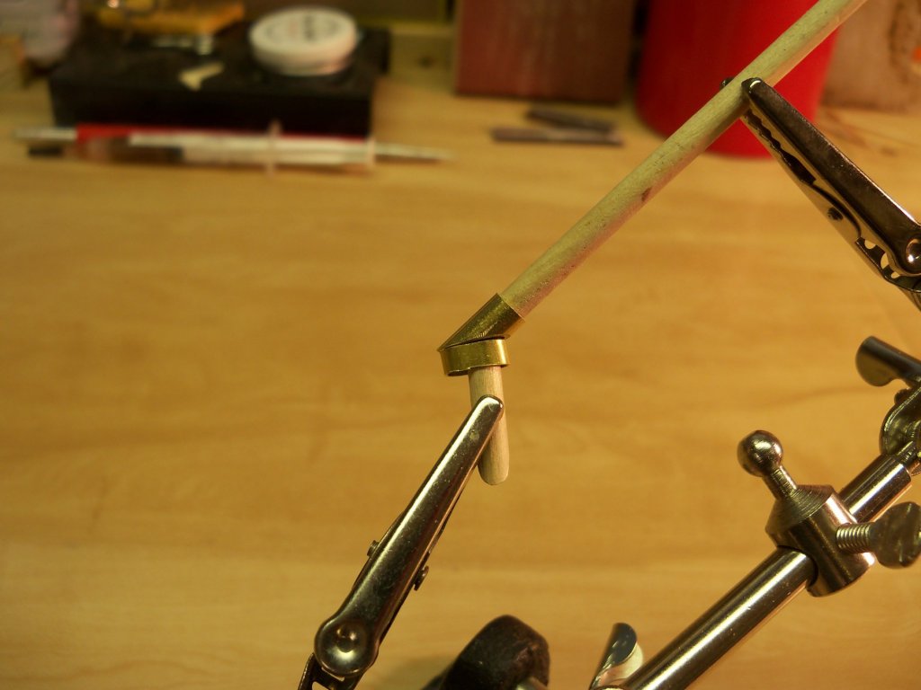
All I had to do then was heat up the metal parts with my torch on its lowest setting and touch a bit of solder on the joint. I guess that I kind of surprised myself by finding that this method worked the very first time! The only drawback that I noticed was that the dowels didn’t take kindly to being so close to a flame. They charred so badly that they had to be replaced to do the other pair.
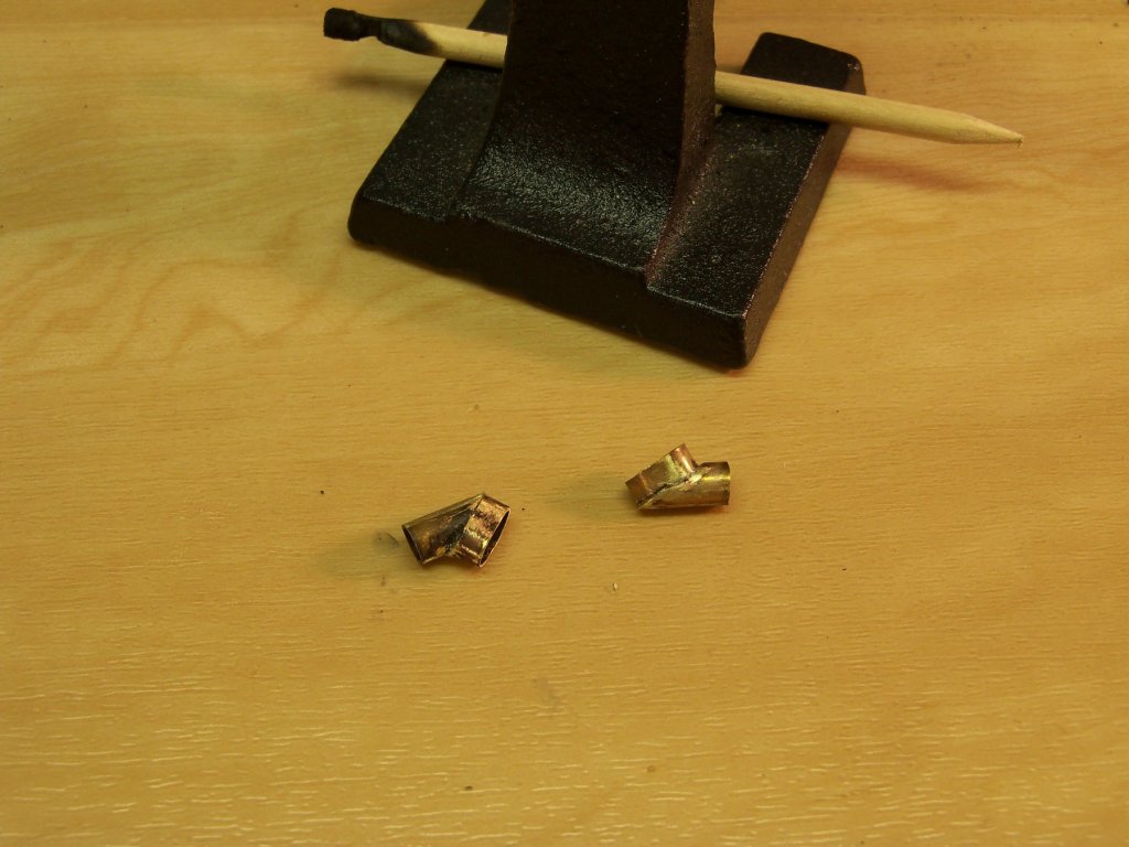
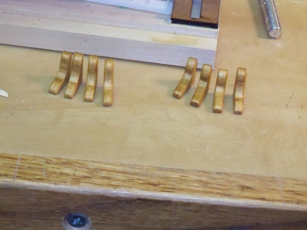
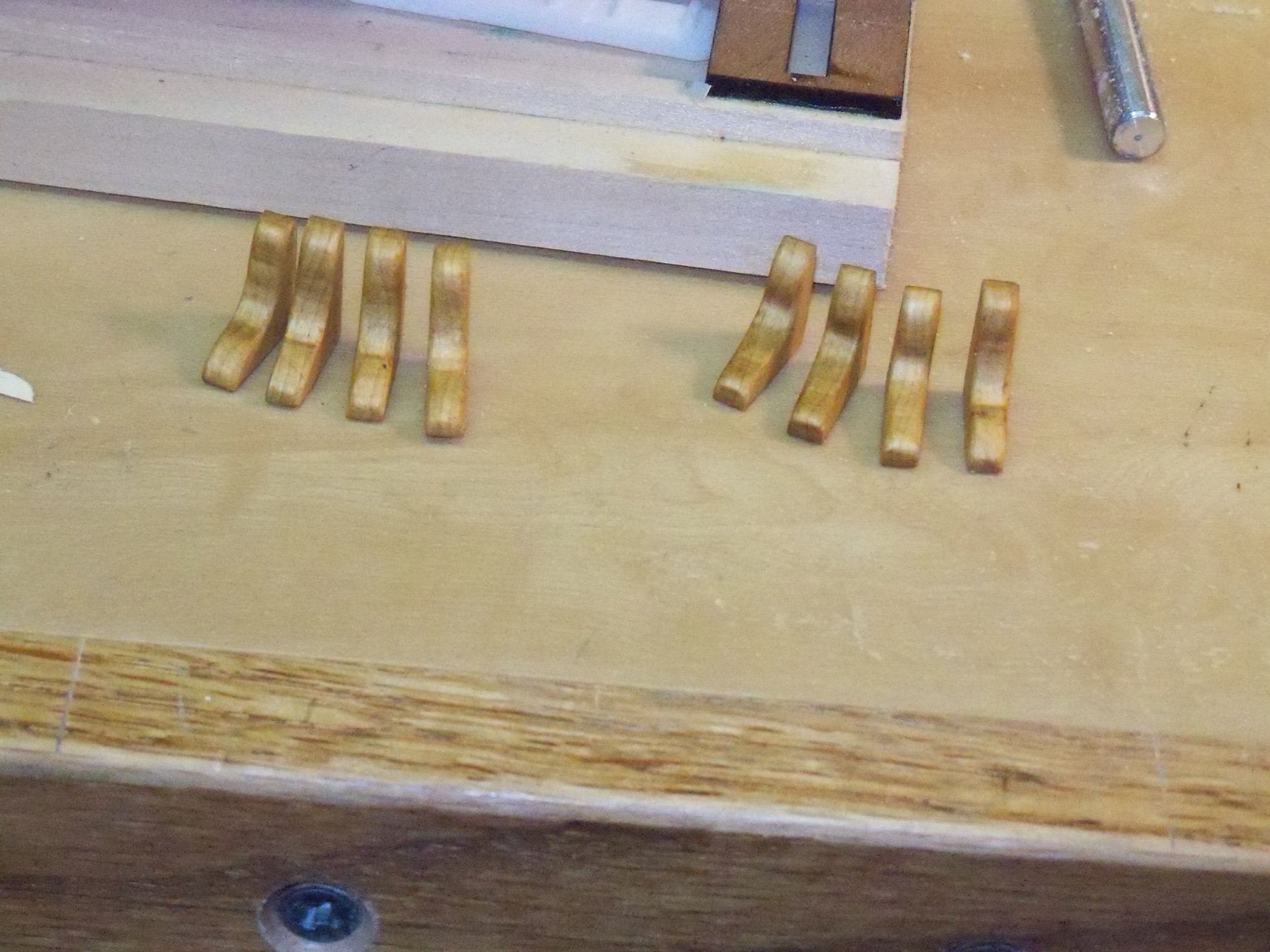
Here are the two hawse pipe assemblies after a little clean up with some sandpaper. I am a happy camper now!
Taking one half of the finish decking to my vise, I clamped it between two scraps of wood to carefully refile the holes in the deck to match the top of the new hawse pipe fitting. With much trial and error I made the opening angle toward the hole in the hull and accept the fitting with a tight push fit. I aligned the matching false deck with the finish deck and scribed the outline of the opening onto the false deck. The false deck hole was cut a bit larger to help when aligning the fitting with the decks when the two of them finally get glued down.
Now the other half of the finish deck was aligned with the completed deck so I could match the size and orientation of the two openings. I repeated the above procedure for the other false deck and decided that I should probably quit for the day and not push my good luck on my build too far for one day. So anyway, here are the four pieces of the deck as they stand right now.
.thumb.JPG.92adc60d8265b0cdbcfe0fcbc6ba145e.JPG)
-
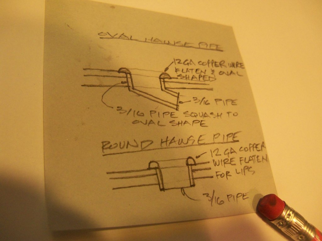
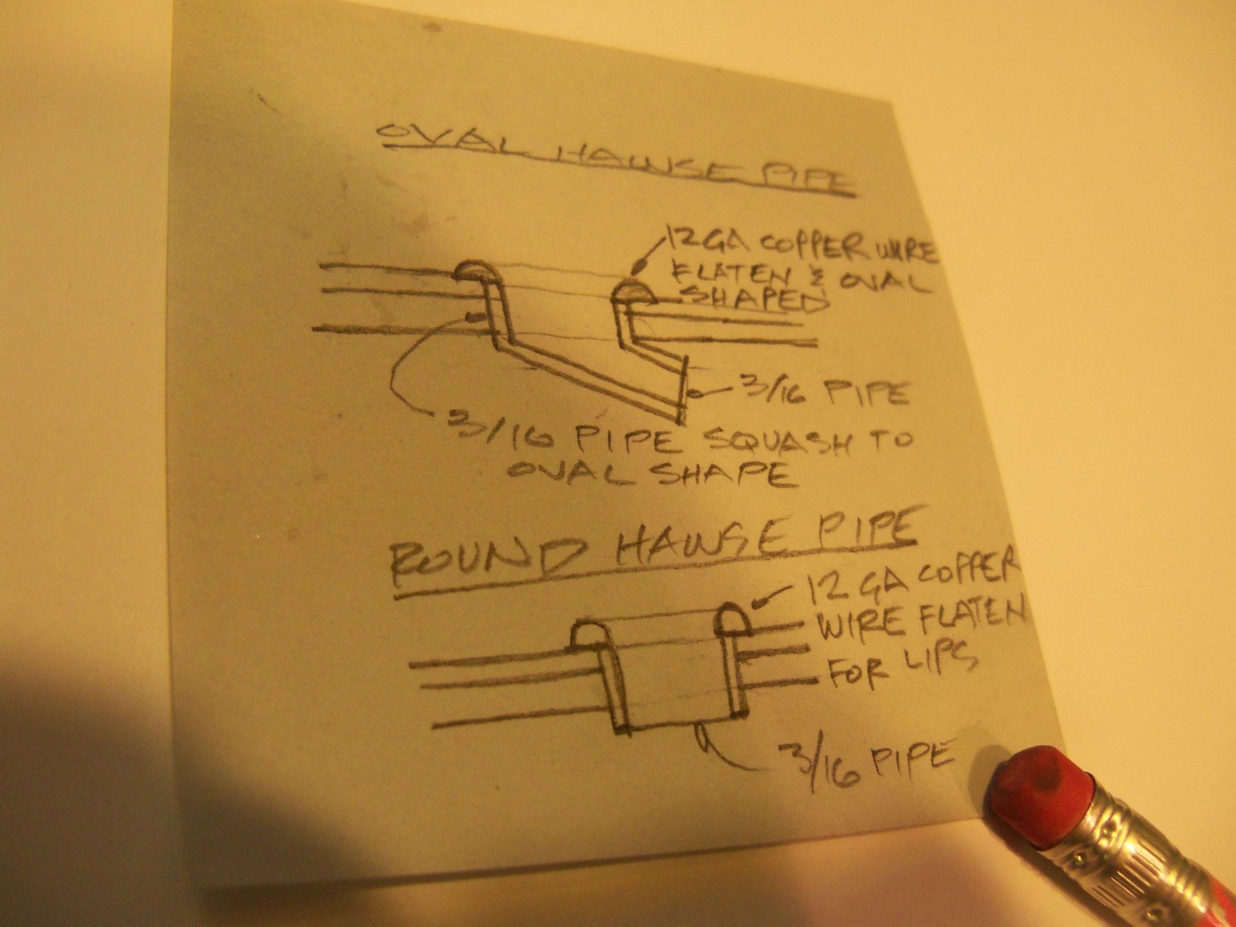
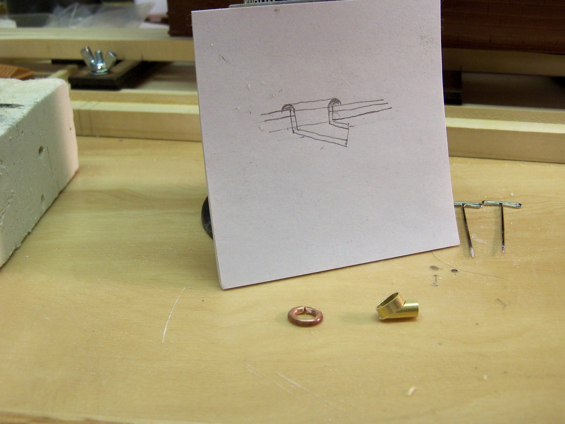
I drew up a couple of sketches of how to make the hawse pipe openings as shown below.
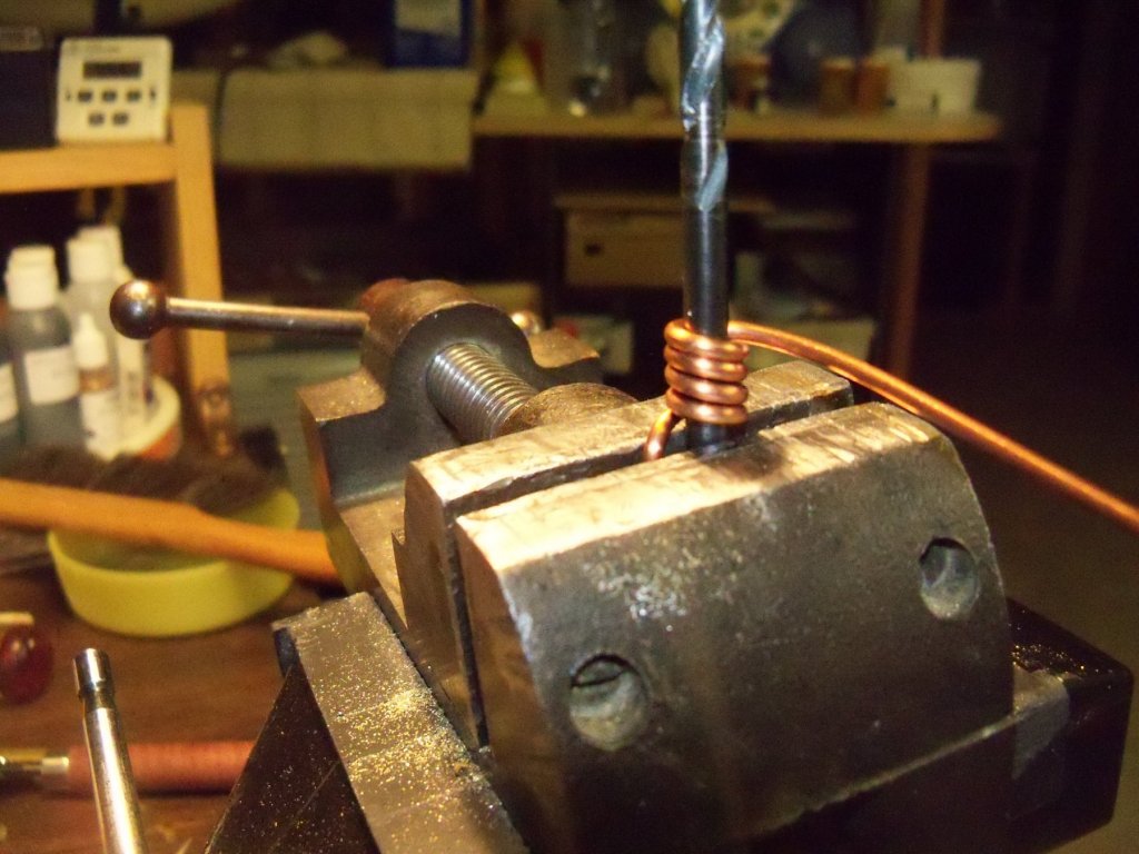
Taking a length of 12 GA solid copper wire left over from wiring the shop I stripped off the insulation. I thought that the diameter of the wire looked to be just the right size for making the lips to scale. (This is similar to a commonly used method of making split rings.) I clamped a 5/32” drill bit in my vise and bent one end of the wire alongside of it in the jaws of the vise. With the free end of the wire held with a vise grip pliers, the wire was tightly wrapped around it about eight times to allow me to have extras in case of failed attempts.
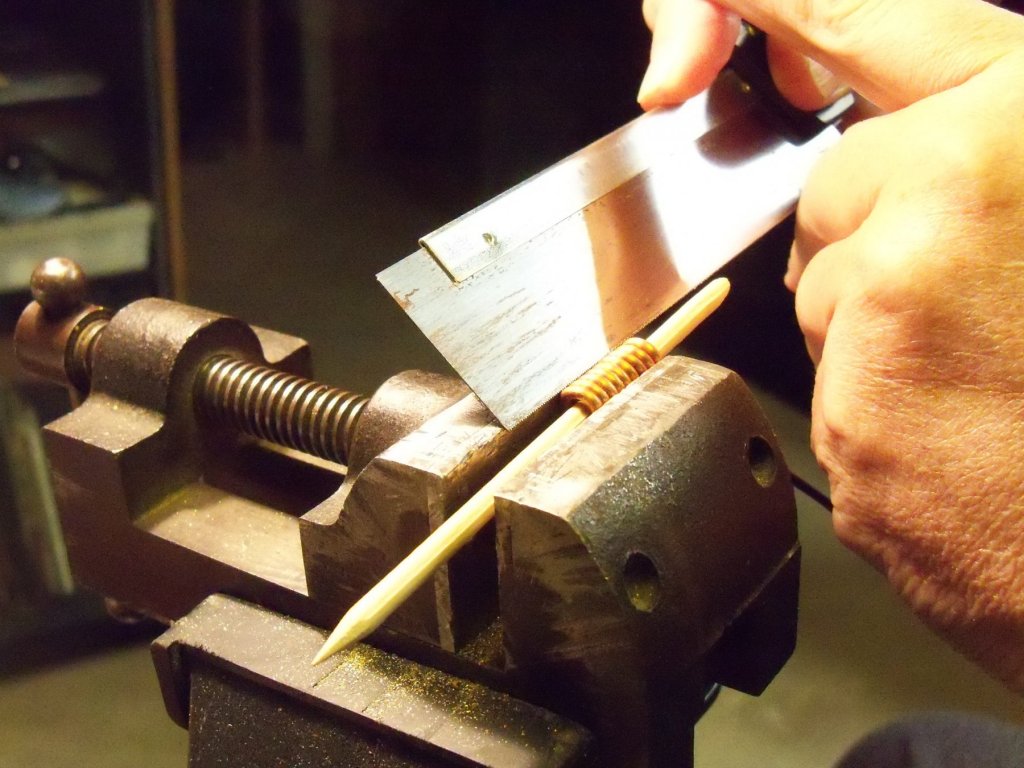
Once the drill bit was removed from the coil of wire, I used my soldering torch to heat the coil until it was a nice cherry red to make it more workable. When the wire cooled off, a stick of 5/32” dowel was slid into the coil and they were clamped lengthwise in my vise to allow me to cut the rings of wire loose with a fine bladed stiff backed saw.
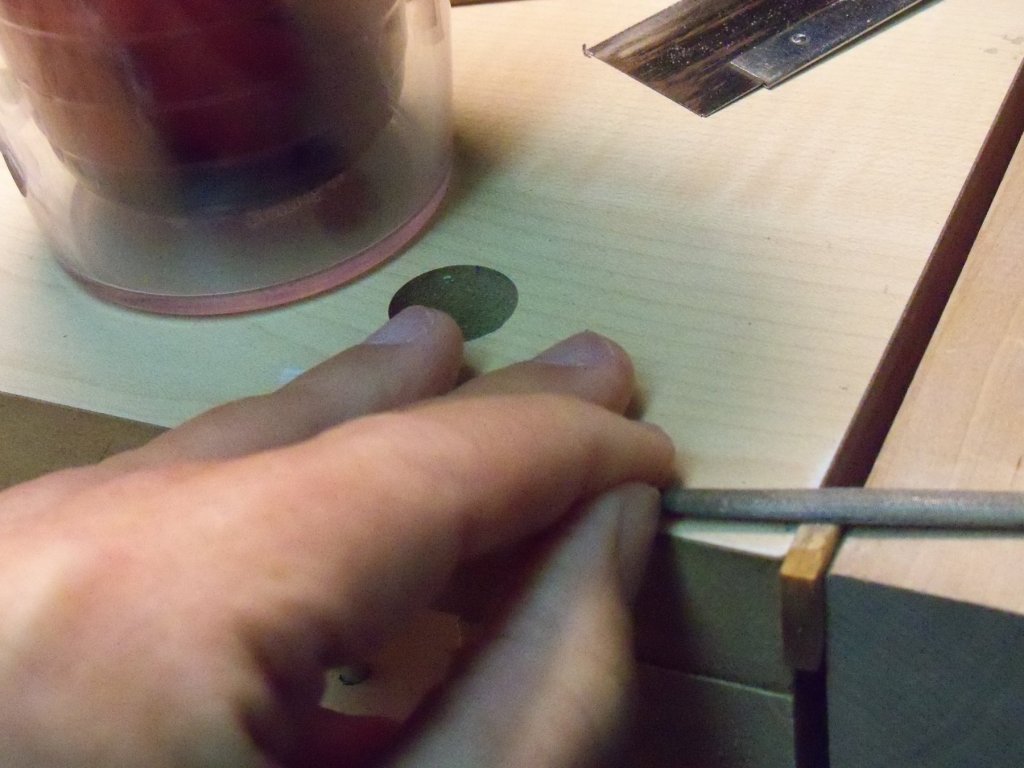
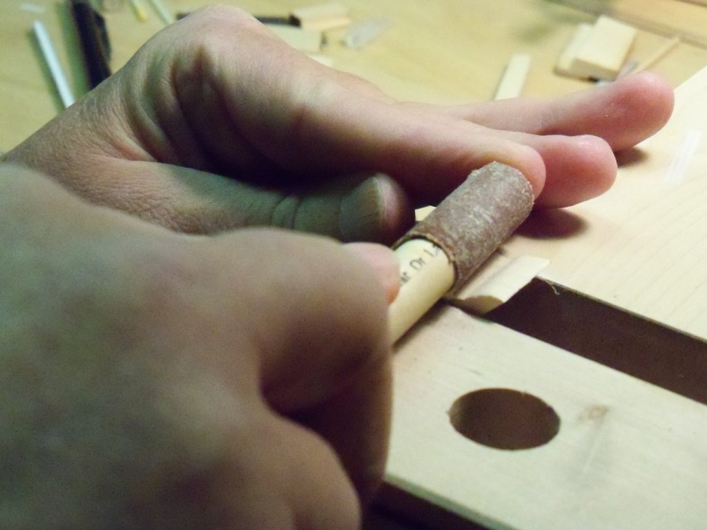
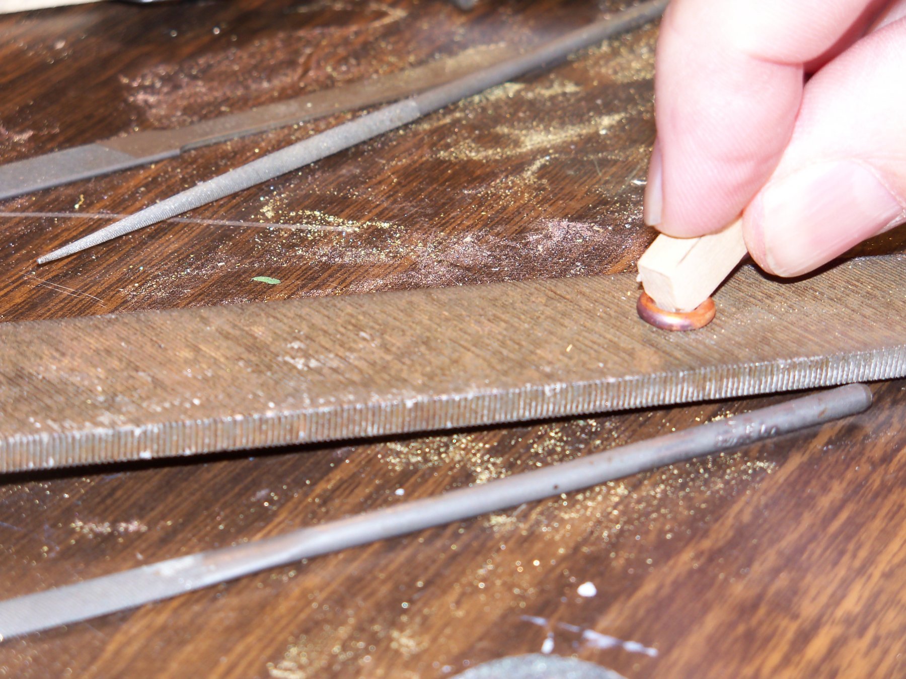
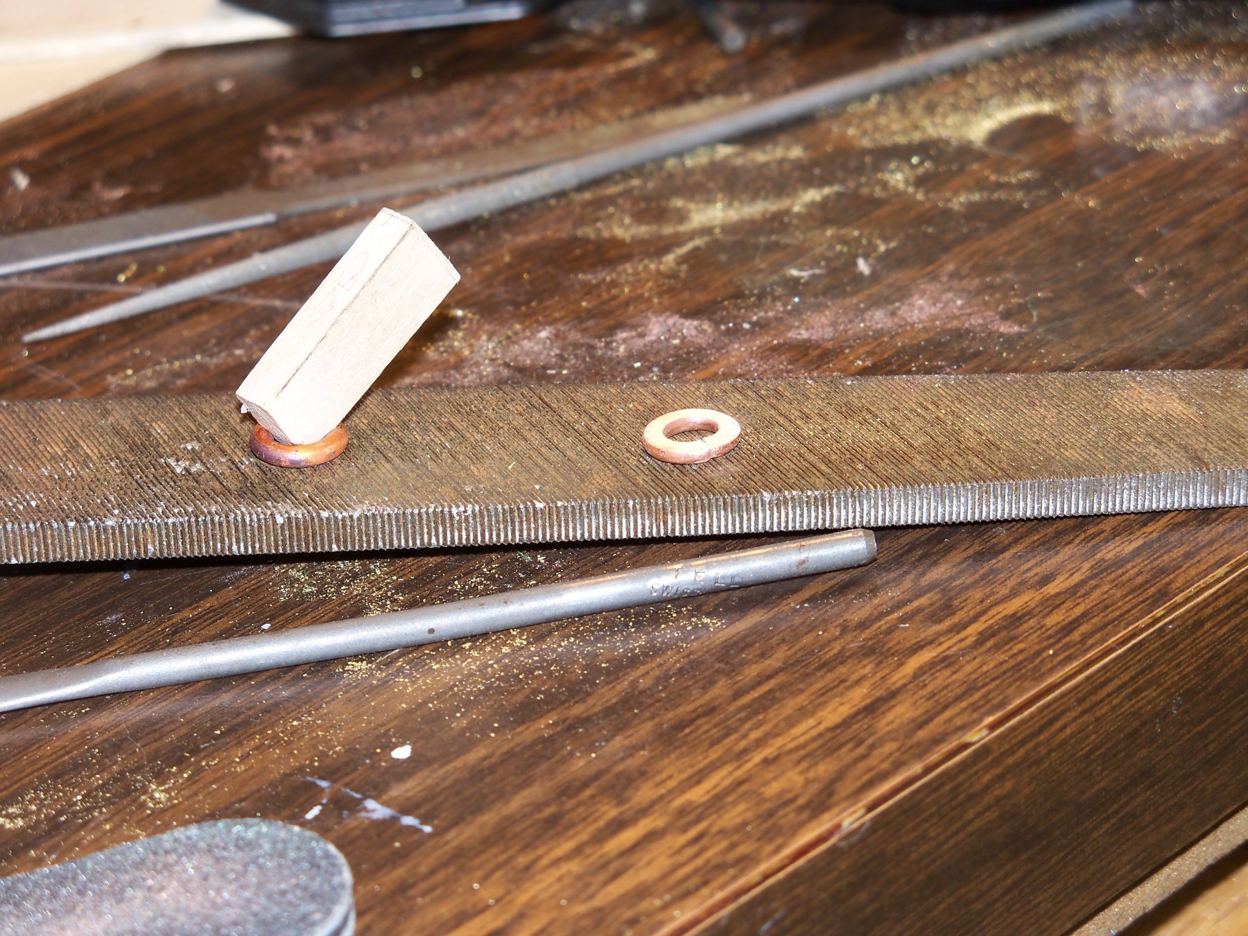
Having six good rings cut loose, they first were flattened and then squeezed closed in my vise. Since the lips needed to be formed with a half round profile, I laid them flat on a large metal file and with a short piece of soft wood for a handle they were filed flat on one face. The piece on the bottom photo has been properly flattened.


While the copper was a little softer when heated up, each ring still took me more than 100 strokes each to make them flat. Perhaps I should have come up with a different method of flattening them with a power tool as it really took a toll on my shoulder!
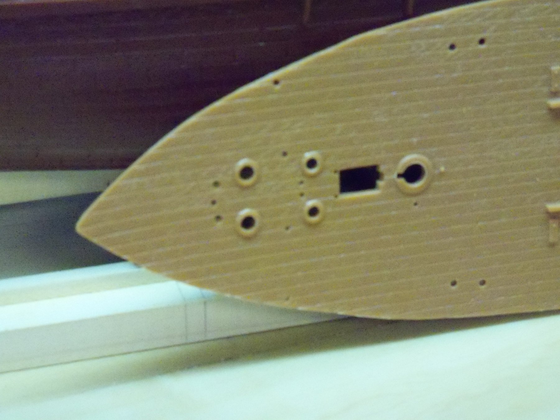
When all six rings were finally flattened, the joints were soldered closed and filed smooth. Taking another look at the blueprints they showed that the upper end of the hawse pipe came through at a sharp angle and thus the opening needed to be oval shaped, contrary to the round openings formed on all four of them on the Aurora kits deck below, so I simply squeezed them in my vise until they looked right.

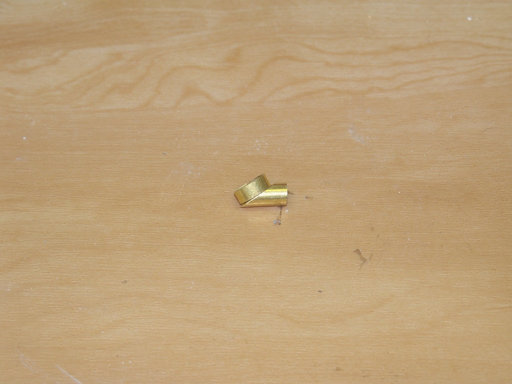
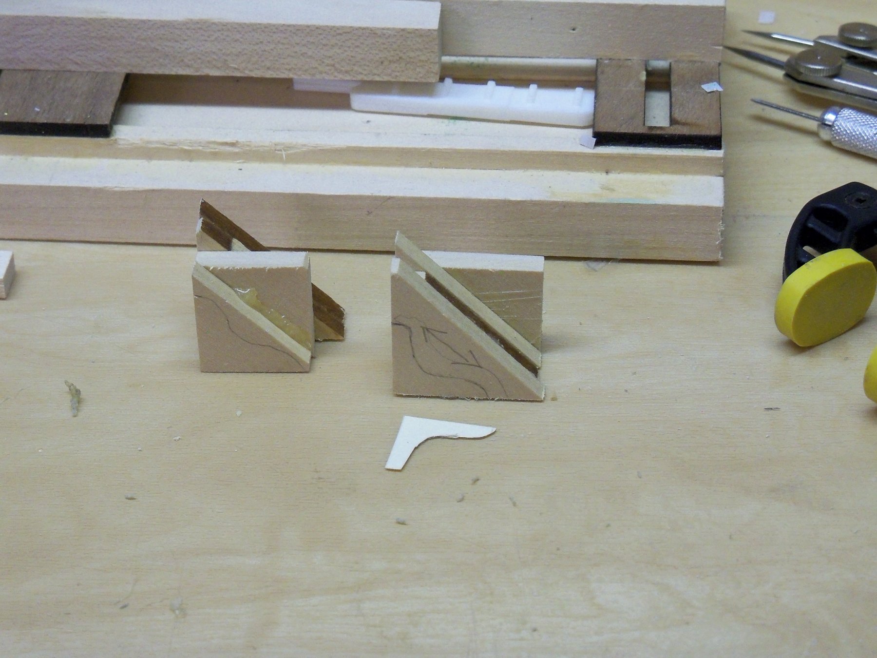
Returning now to the pipes themselves, the two openings just aft of the windlass leading down to the anchor chain lockers would only need a short straight length of pipe, so that would be easy enough to do. However, as I drew up the sketch (shown previously above) of the angled pipe situation, I figured that the oval shaped openings would require two pieces each. One would just be a very short length of pipe filed down at a sharp angle on the top end where it meets the bottom side of the deck, while other one needed to match that oval shape and its length needed to match the thickness of the deck. These two pieces will need to be soldered together as shown below temporarily held together with some rubber cement.
Once the pipes are finished and blackened, the holes in the deck will be trimmed to match, the pipes glued in place, and the lips glued down with CA. Then with the anchor chain threaded through all the holes the deck can be glued in place.
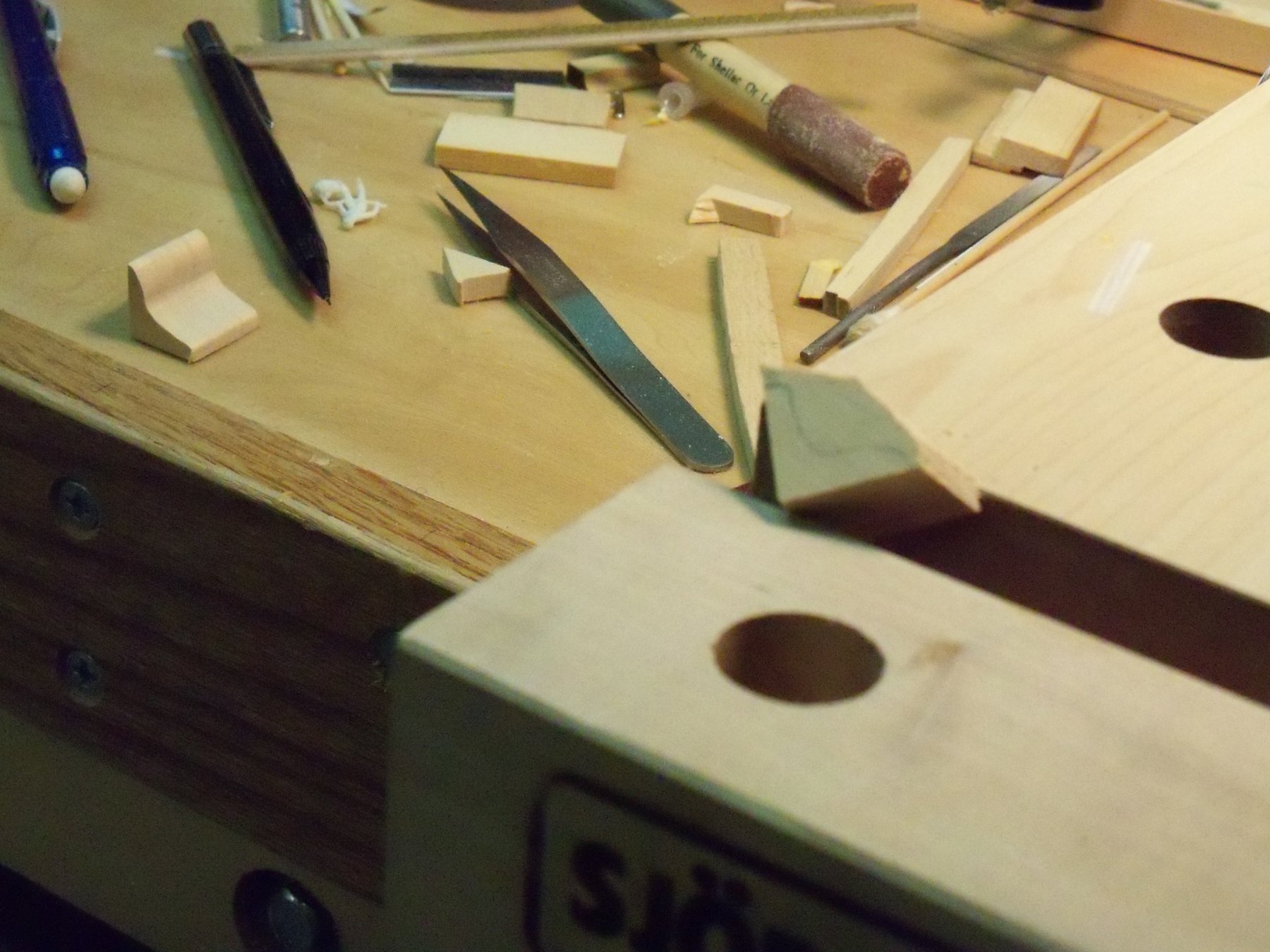
I seem to be having a difficult time soldering the small pieces of the tubing together as I can’t keep the pieces from separating while using my torch. I think I’ll try to get some suggestions from MSW or think up another solution myself. I guess it’s a good time to take a break!
-
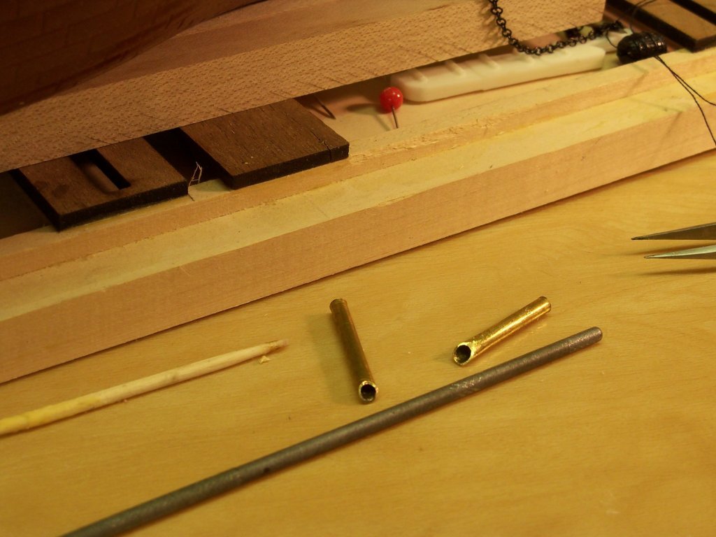
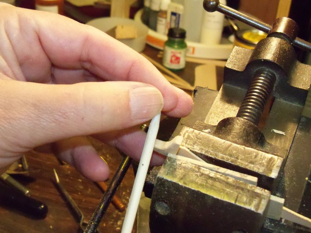
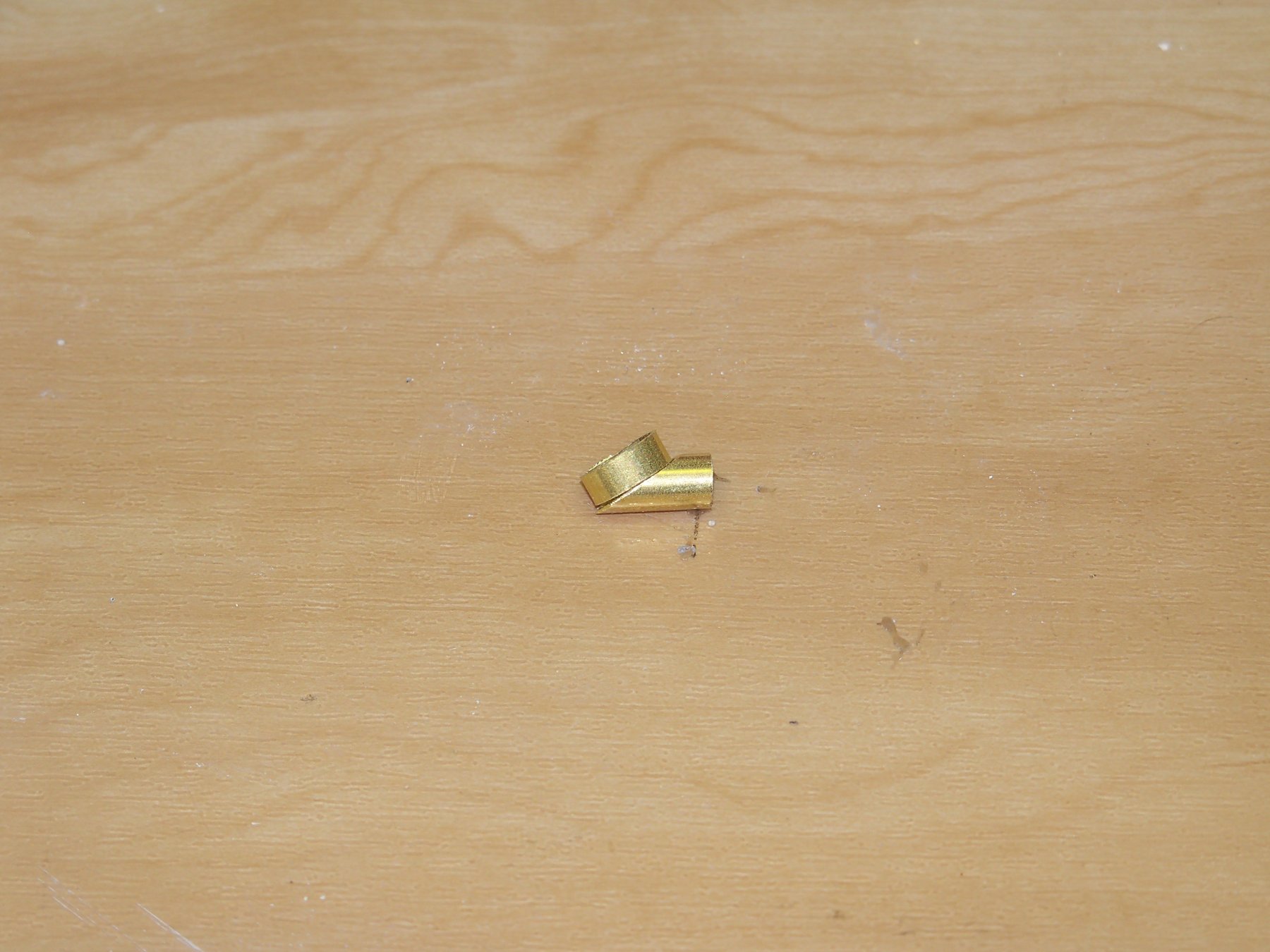
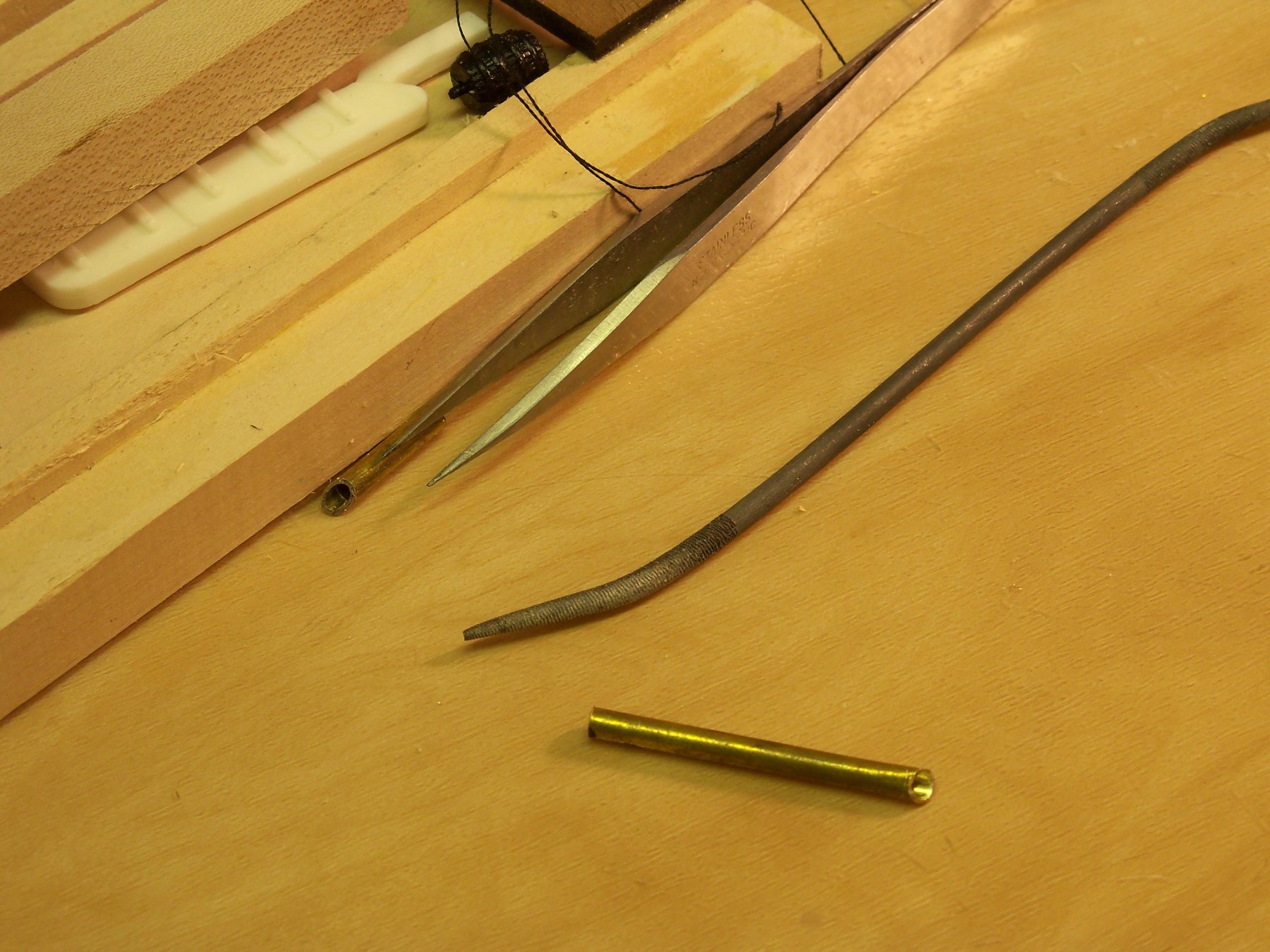
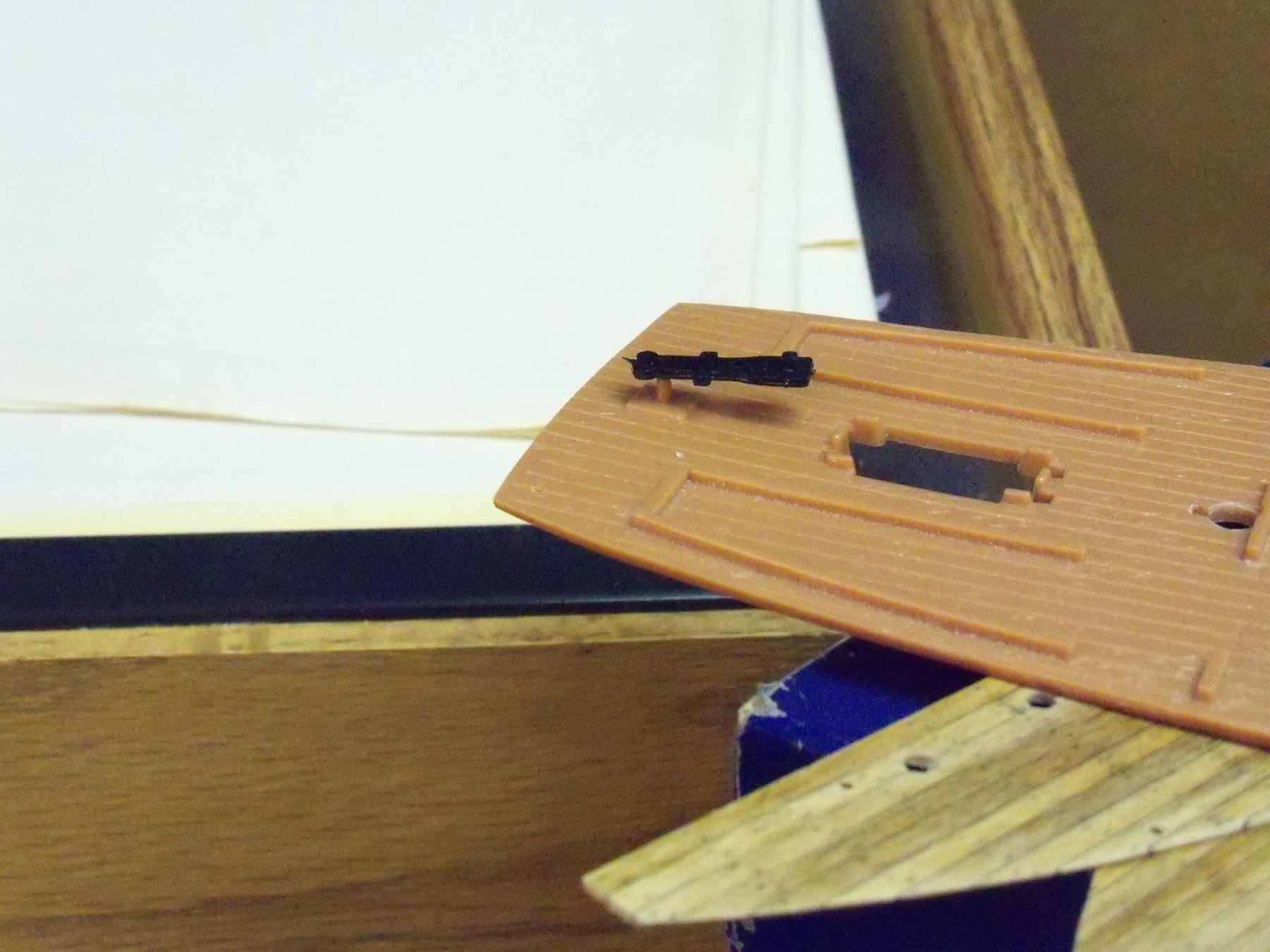
I am having quite a time trying to hold two tiny pieces of thin wall brass tubing in place while soldering. I have seen some people using wire to hold them in place but how can you do it without soldering the wire to the parts? I have a soldering torch but it just seems to blow the parts away from each other. Here is a photo of the parts in question and a sketch of how they go together below.

The assembly is the deck end of the hawse pipe on the whaler Wanderer. The flattened copper oval will serve as the lips of the pipe and will just be glued with CA once the pipe is inserted into a hole in the deck. I have checked through this topic but don't see any posts concerning this problem. Anyone have any suggestions?
- thibaultron and mtaylor
-
2
-
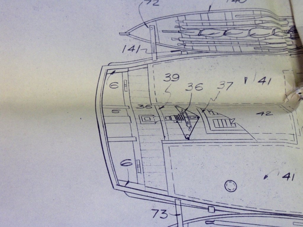
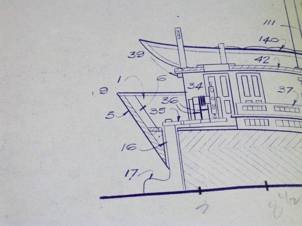
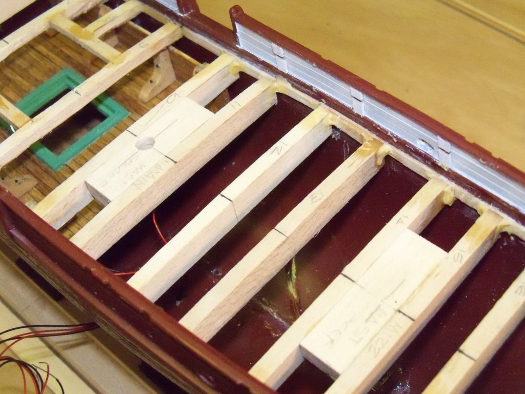
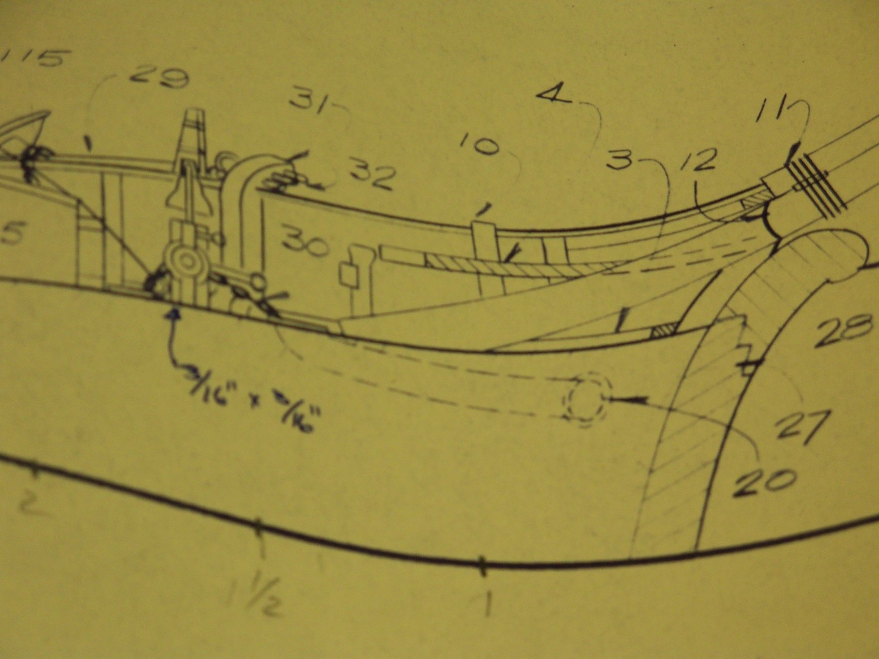
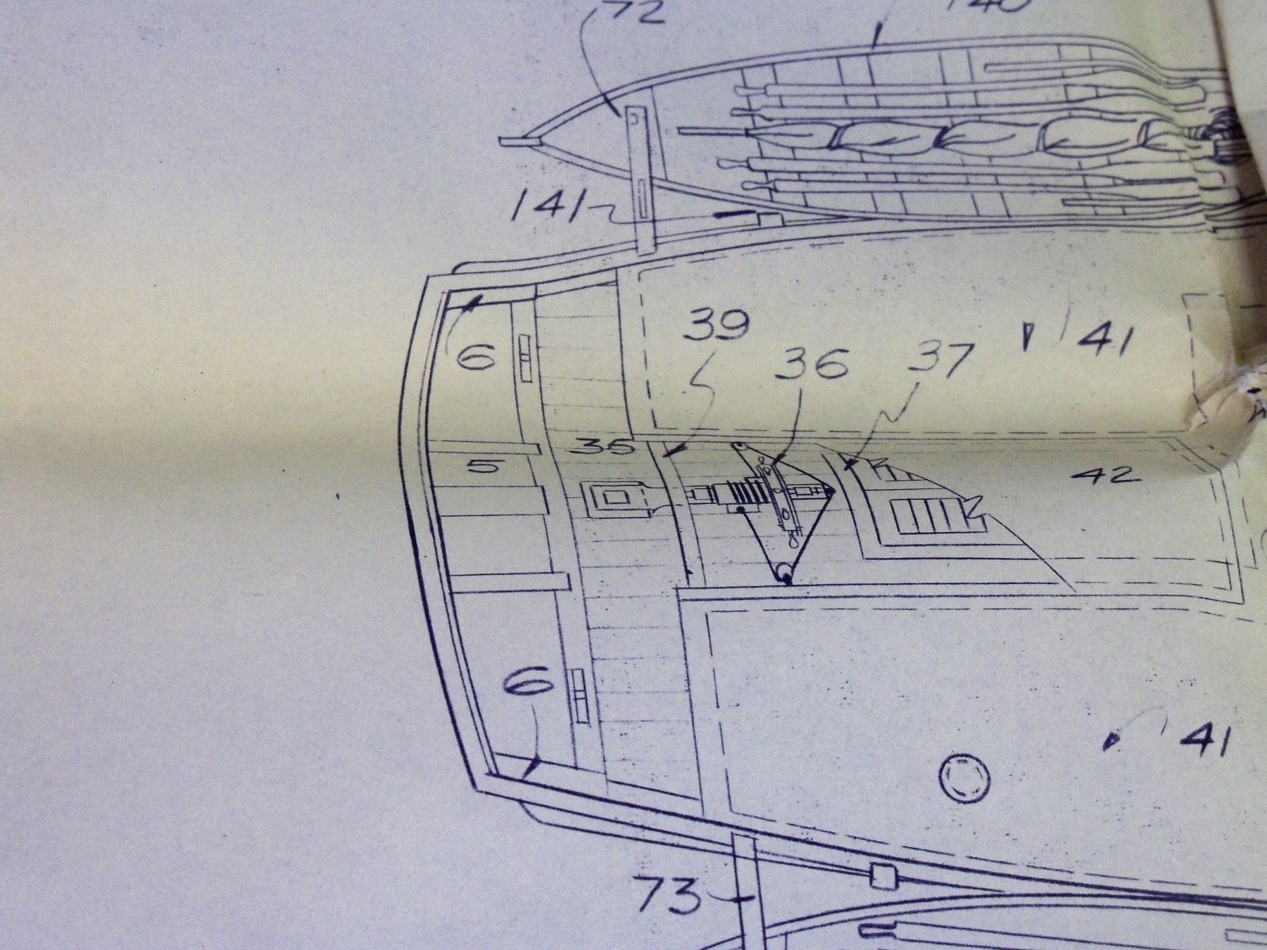
These are two shots of the blueprints at the bow showing the details of the hawse pipes.
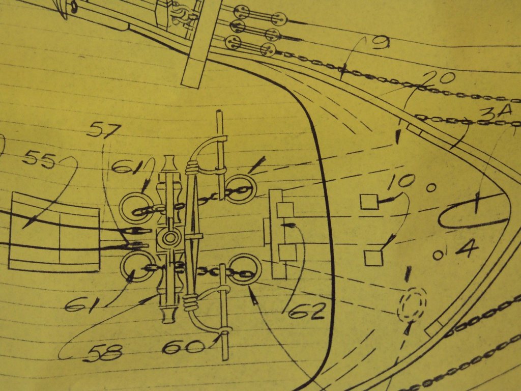
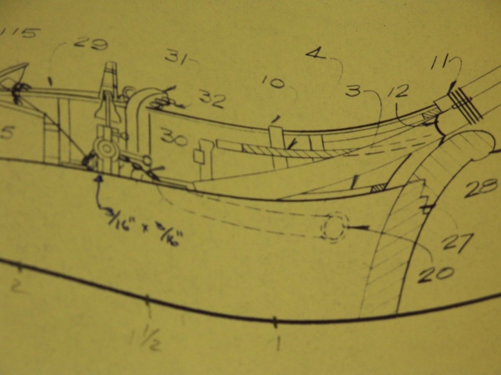
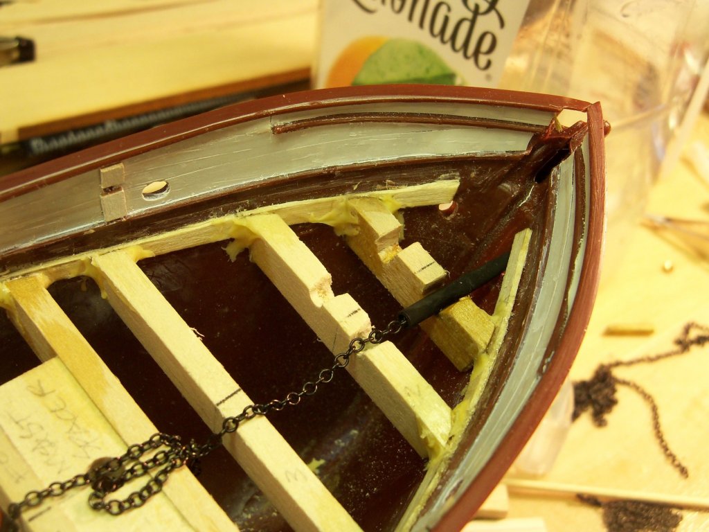
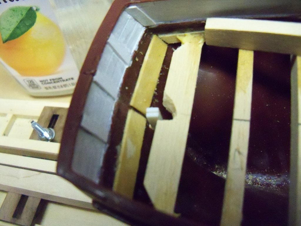
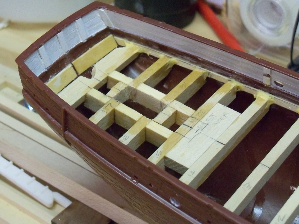
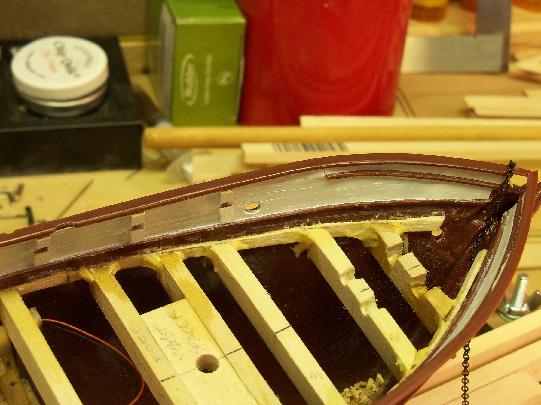
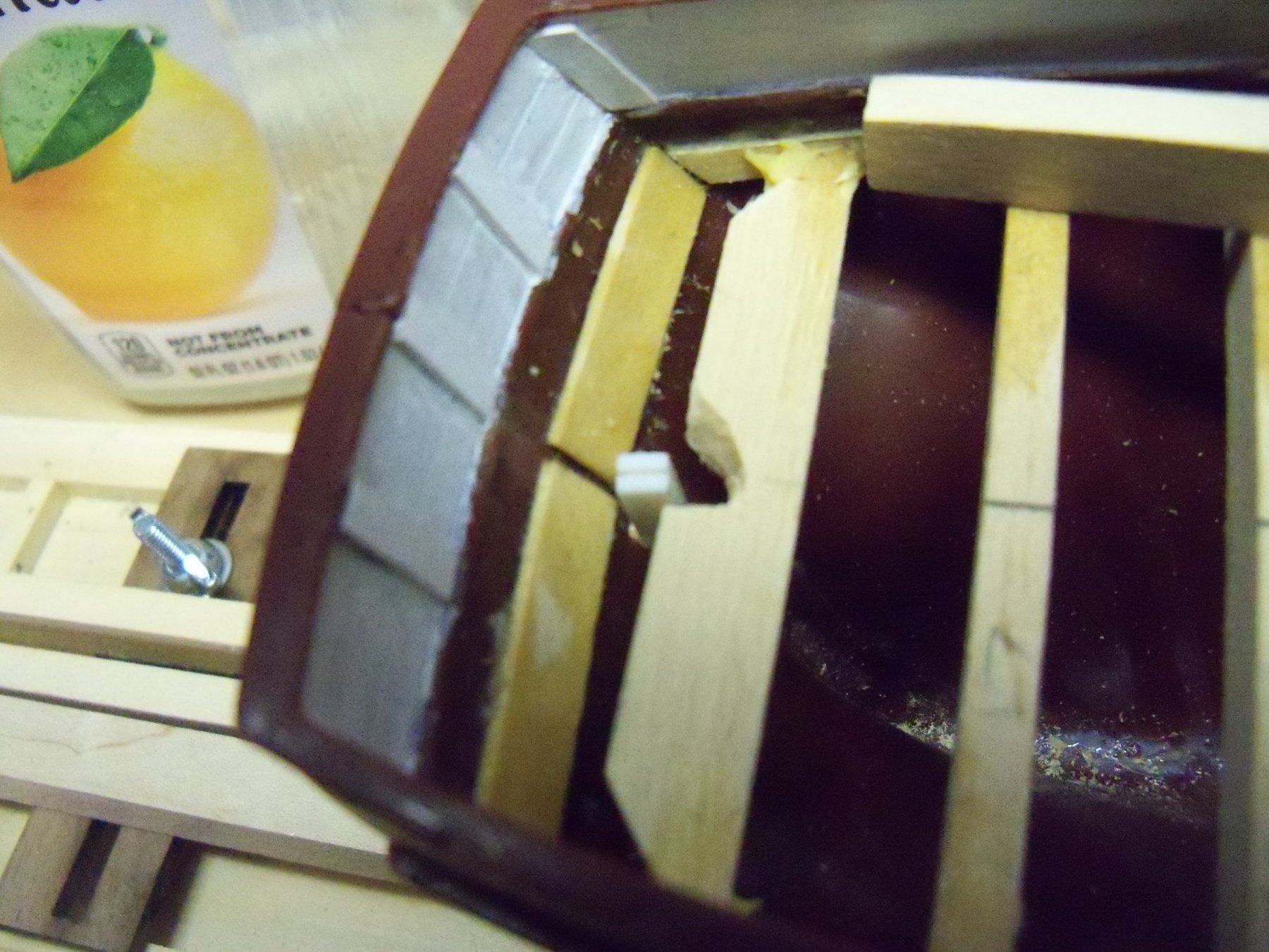
You can see that the anchor chain travels from the hawse pipe opening at the bow, then up through the deck, around the winch, and then back down through the deck. The first step was to cut out some notches in the frames for the pipes as shown below.

Through some rather poor planning on my part when spacing the beams, I put beam #2 right where the upper end of the hawse pipe turns up to go through the deck. Taking some 1/8” brass tubing, I first beveled one end with a file by trial and error to match in with the hull at the hawse hole. Then I cut that section of tubing off to end at the edge of beam #2.

So far, it looked good so I cut the other one the same.
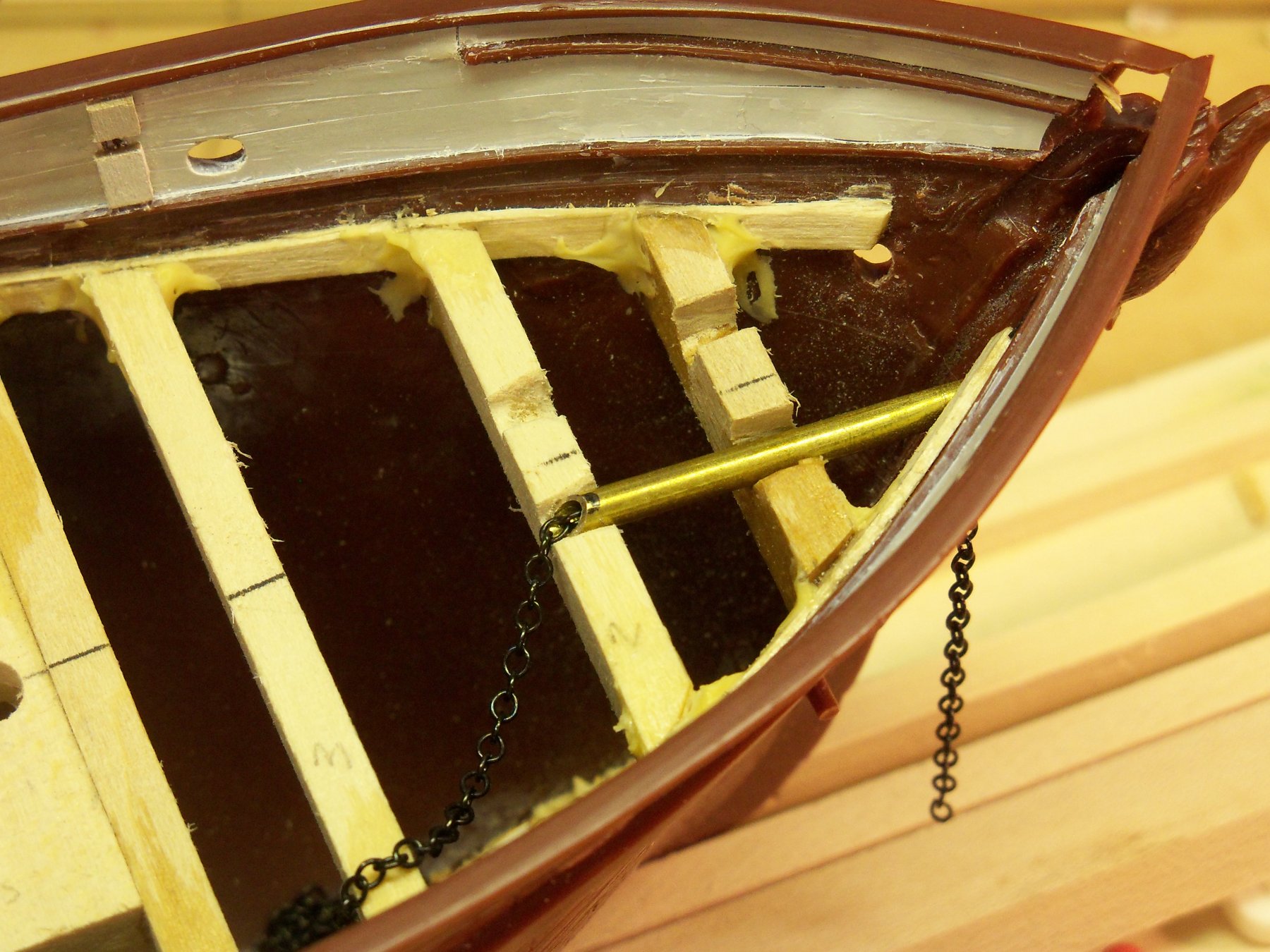
In order for the chain to go up through the deck, I mitered the end of the tube to let the chain make that bend. Tilting the hull bow up, the chain was passed through the pipe.

I tried to pull the chain up across the edge of the miter, but found that it didn’t want to go. Thinking that I would just shorten the pipe short of beam #2 to allow the chain to make its own way around the bend I tried pulling the chain again and found that it seemed to work a little better. So I did the same to the other pipe and coated both of them in brass black and let them dry. I then glued one in place with some thin CA to test it again.
Apparently all the coating did was just increase the friction between the pipe and chain and it didn’t function as well as I would have liked. It was time for me to rethink this whole detail.
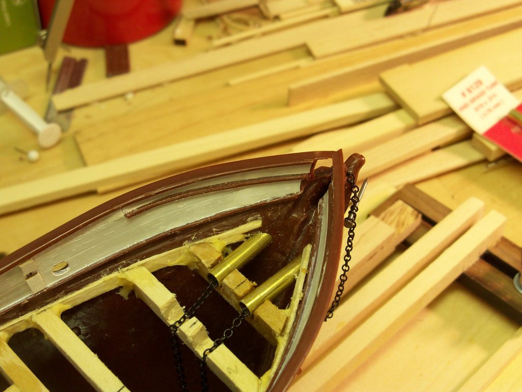
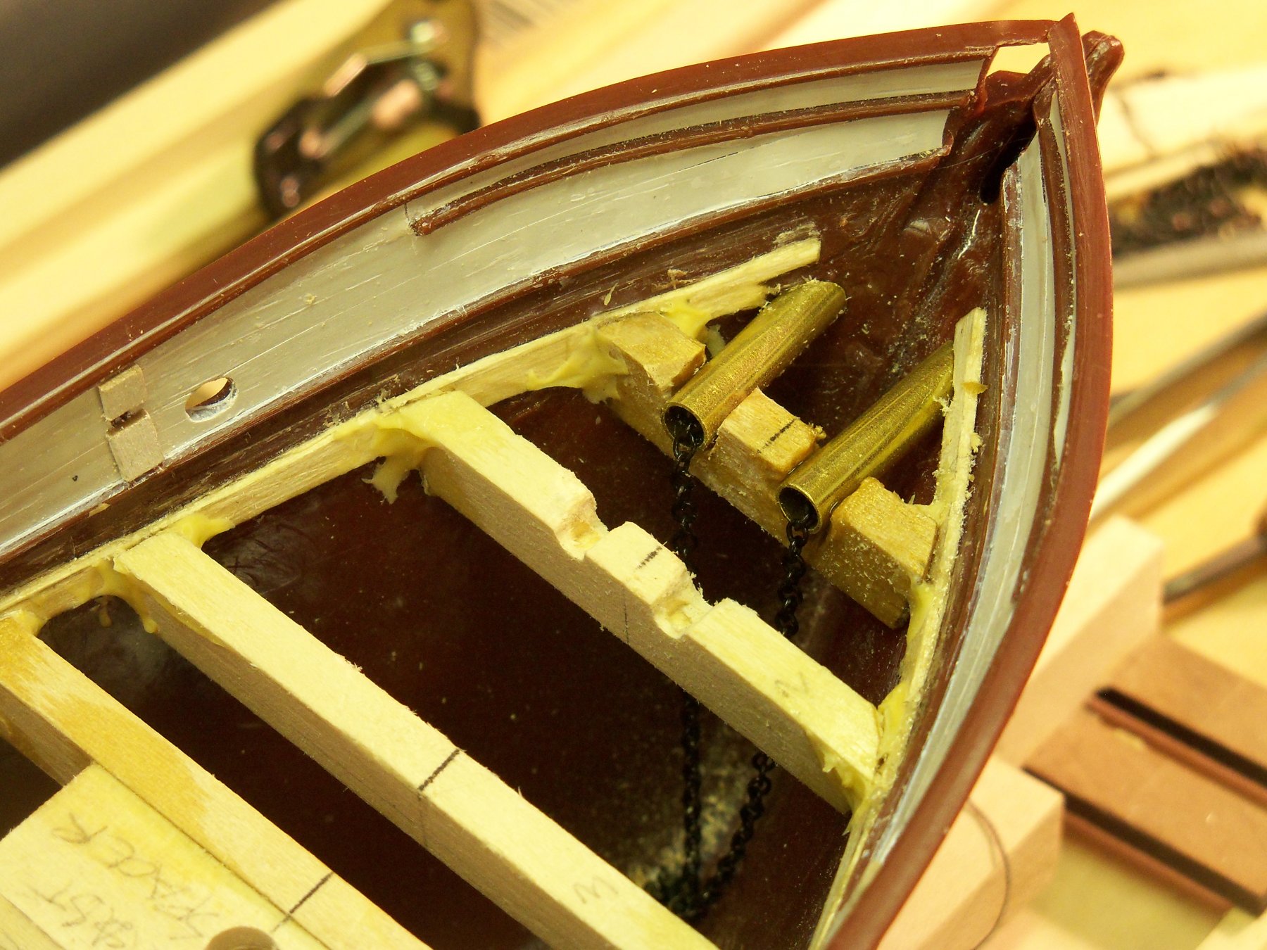
So now, looking a bit closer at the blueprints, I realized that the hawse pipe just needed to be larger. The too small pipes were then pried out and I started over with two 7/8” long sections of 3/16” brass tubing. Of course that required reworking the notches to allow the larger pipes to fit flush with the bottom of the false deck, but between the larger pipes and no coating applied, the chain now slid quite freely. Both pipes were therefore glued in place.

I guess that it was just a bit of overkill with the brass black as when the chain was in the pipe I wasn’t able to see the brass tubing anyways. Now I was left trying to figure out how to make the end of the hawse pipe where it went through the deck. Again taking the 3/16” brass tubing, a section just long enough to go through both the 1/16” false deck and the 1/32” finish deck with a little extra above for the lips and maybe a bit more below decks to give the illusion of a hawse pipe. Therefore, the notches on beam #2 were also cut larger to accommodate those sections of tubing.
Now I’ll have to contemplate just how to make those lips on the exposed portion of the pipes on deck.
-
Just a note here to say that my plans from A.J. Fisher that I have based most of my speculations about the details of the Wanderer were originally drawn by Captain E. Armitage that first appeared in three issues of Popular Science magazine back in 1932. He, himself, actually built a model of her based on those plans. They are the most complete version of this ships’ construction and details that I have been able to find. I felt fairly confident that, as he was able to actually go aboard the ship to take photos and measurements just before she started out on her last tragic whaling voyage, that the information was accurate.
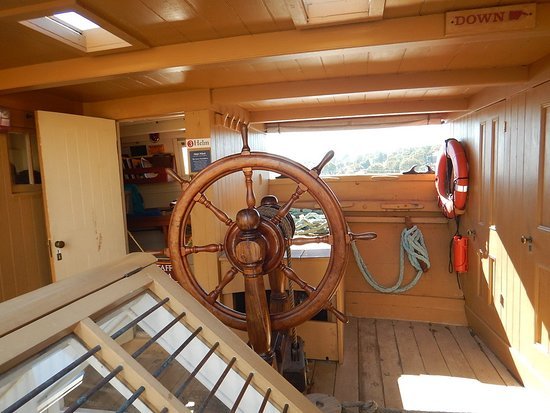
While many of the details of the Wanderer and the C.W. Morgan are similar, the sterns differed quite noticeably. Once again referring back to a photo on the Mystic Seaport website you can see that the stern deck cabin on the Morgan continues right into the transom with the rudder shaft portion of the steering gear housed in a small enclosure (see below), but the Wanderer deck cabin stops short and has the stern portion of the deck exposed with the entire steering (commonly referred to as a shin knocker) mechanism exposed.
What was provided in the Aurora kit is somewhat true to form in that it’s exposed, but it’s still a far cry from what was actually on the ship. Anyway, I hardly think that this small pin (shown below) through the deck could handle turning that large rudder!

So, I went back to my drawings from A.J. Fisher to determine how to show this detail. The deck plan and the cross section shown on the blueprints below indicate that the rudder shaft continues through the hull and, although reduced somewhat in size, the actual rudder shaft is notched down, passed through the tiller and pinned with some type of through bolt.
The drawing below included with the blueprints shows a good illustration of this detail.

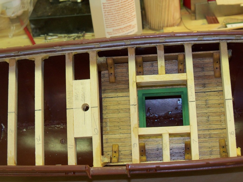
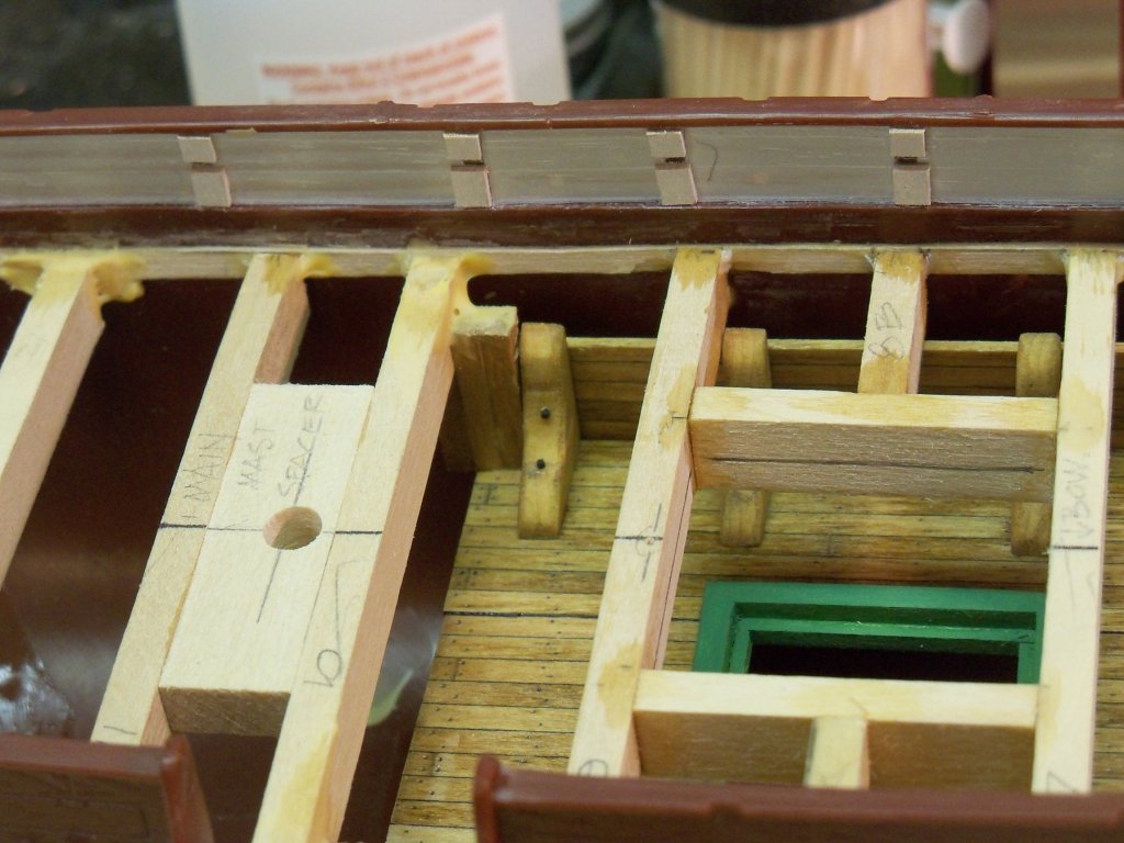
Since the shaft of the rudder supplied with the kit is way too short, I think that I will just make a new one. So, the first order of business was to notch the last floor support beam to allow the shaft to pass through the deck and into the tiller.
As I was making that notch with a drill and rasp, I decided that putting another LED light below the skylight would also be a nice touch. For the light to show better, I needed to clear an opening for the light to show through better. The inside face of the skylight was measured and marked on the beams. Rather than replacing the existing beams and re-framing the whole area, I just remodeled the opening a little.
First cutting some reinforcing blocks that were lined up with the inside edge of the skylight; I glued them in place with CA, and let it set overnight (since they would be getting some rough treatment) before cutting back the beams. Once that was done and the glue set up, I took the entire hull to my drill press to remove most of the material by drilling through the parts to be removed at the corners and then paring down the rest of the opening with a chisel.

While I wait for my new order of LED lights to arrive, I will start working on the hawse pipes.
-
Welcome to MSW Mark. Until recently, I had a brother living in Allentown PA. Over the years my wife and I have made numerous trips out that way, and although he passed a couple of years ago, I still have some family in the area.
I am also now confined to a wheelchair, but unlike you, my confinement is now permanent. I have found that keeping a positive attitude like yours can get you through a lot of frustrations. I don’t know your specific physical or financial restrictions, but have you looked into specialty wheelchairs that are available in both manual and power versions that would still allow you to stand?
I have found that one of the most aggravating aspects of life in a wheelchair is the restriction on my reach. I have had to modify most of my power tools and shop over the years for use while sitting in my chair. I was unable to afford this type of wheelchair, but they can make accessing things around your house easier and some cases you may also still be able to access your shops. (Just a little food for thought.)
-
20 minutes ago, ccoyle said:
I don't think that architectural models in general ever get much in the way of weathering.
The few architectural models that I constructed in college were done as in the manuals to be a pristine representation of the building when it's brand new. Clients don't want to see the building that they plan on building and paying for in any kind of disrepair.
-
Here is just a short update. Try as I might, I was unable to come across any photos or sketches of the Wanderer below the main deck (including the 1921 film) so I find myself looking closer to the wealth of info available on the C.W. Morgan which was similar.
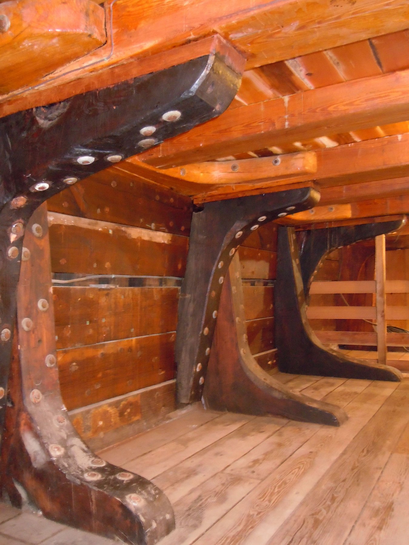
Finally I was able to relocate this photo on the Mystic Seaport web site of the lower deck of the C.W. Morgan.
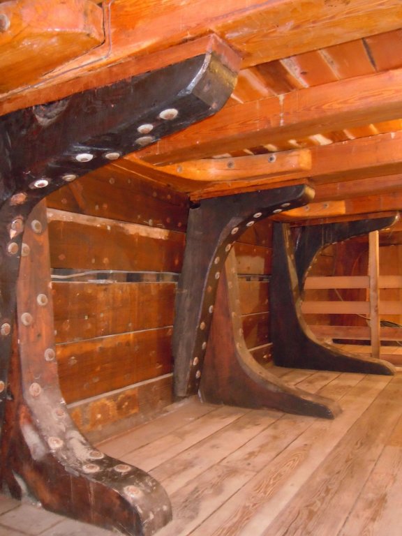
It clearly shows both the knees for the main deck support beams above and the ones on the lower deck floor. You can also see that the knees have more than a dozen bolts each. True, the C.W. Morgan and the Wanderer were different ships, but overall they shared many of the same features and I can’t see why they should differ greatly on this detail.
Well, I did try to remove the lower knees to install more bolts, but apparently they were glued too solidly, as they didn’t want to budge. I was afraid if I tried too hard, I might ruin the lower deck assembly.
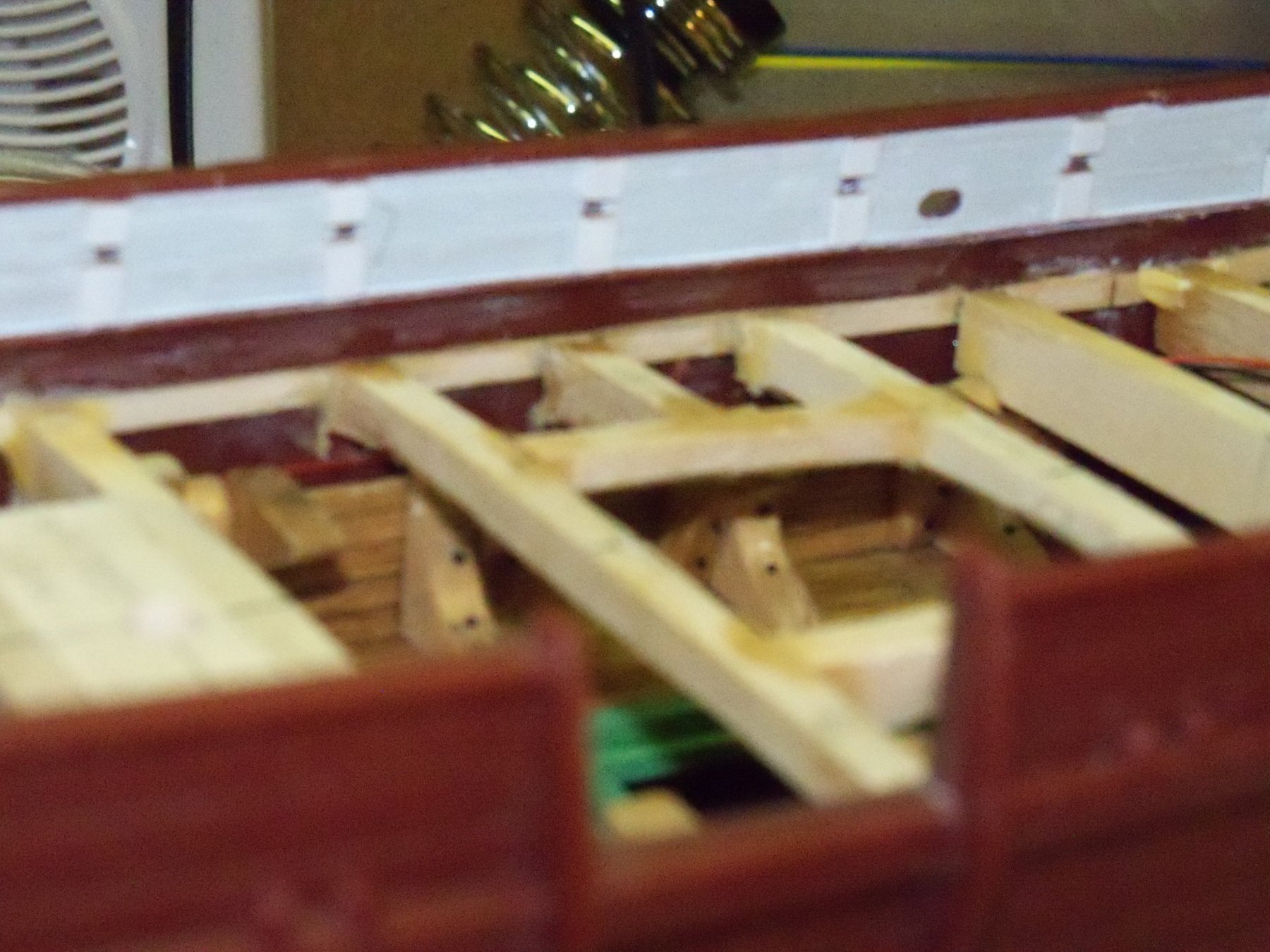
So, I resigned myself to leave them in place as they were and made up the eight new knees for the main deck support beams pretty much the same as the knees previously put in. They don't actually attach to the floor beams above, but that will not be readily visible even with the lights on when the deck above is installed. This is about the best angle available to see them at all.

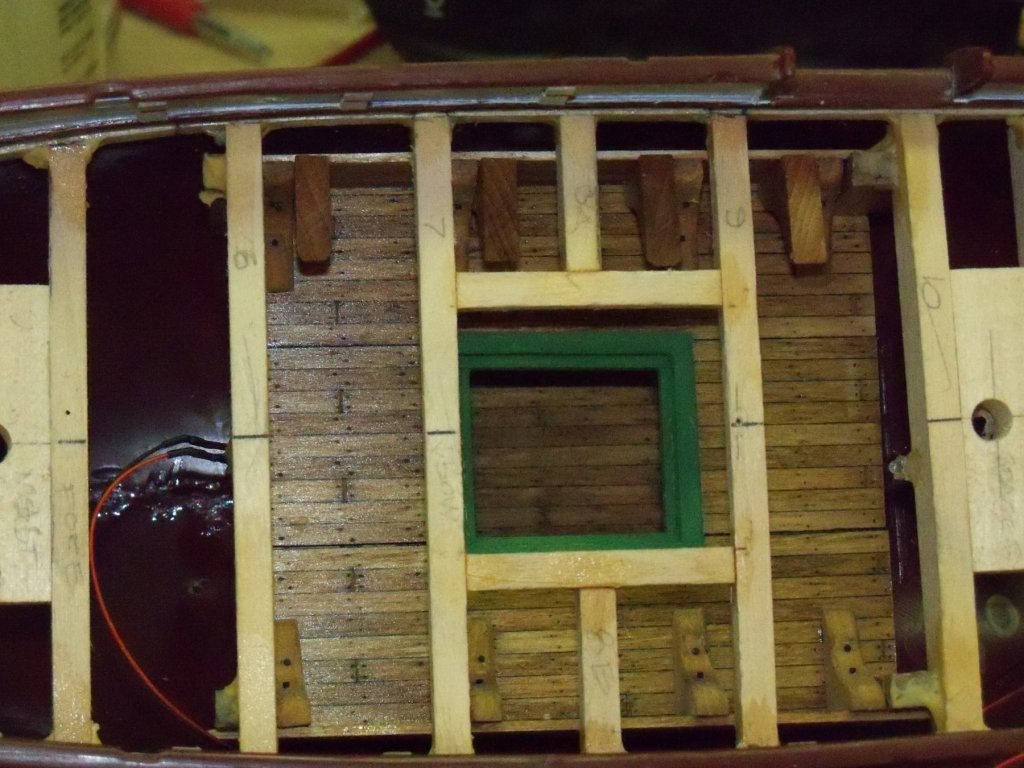
The existing knees had been easier to install as there was still enough room to get access with just my fingers, but they were now reducing the clearance available for the new ones. Since the new ones basically stand on their tips, the hull needed to be laid on its side so gravity would allow me to attach them on the inner hull walls and the other knees. The photo below shows one side complete.
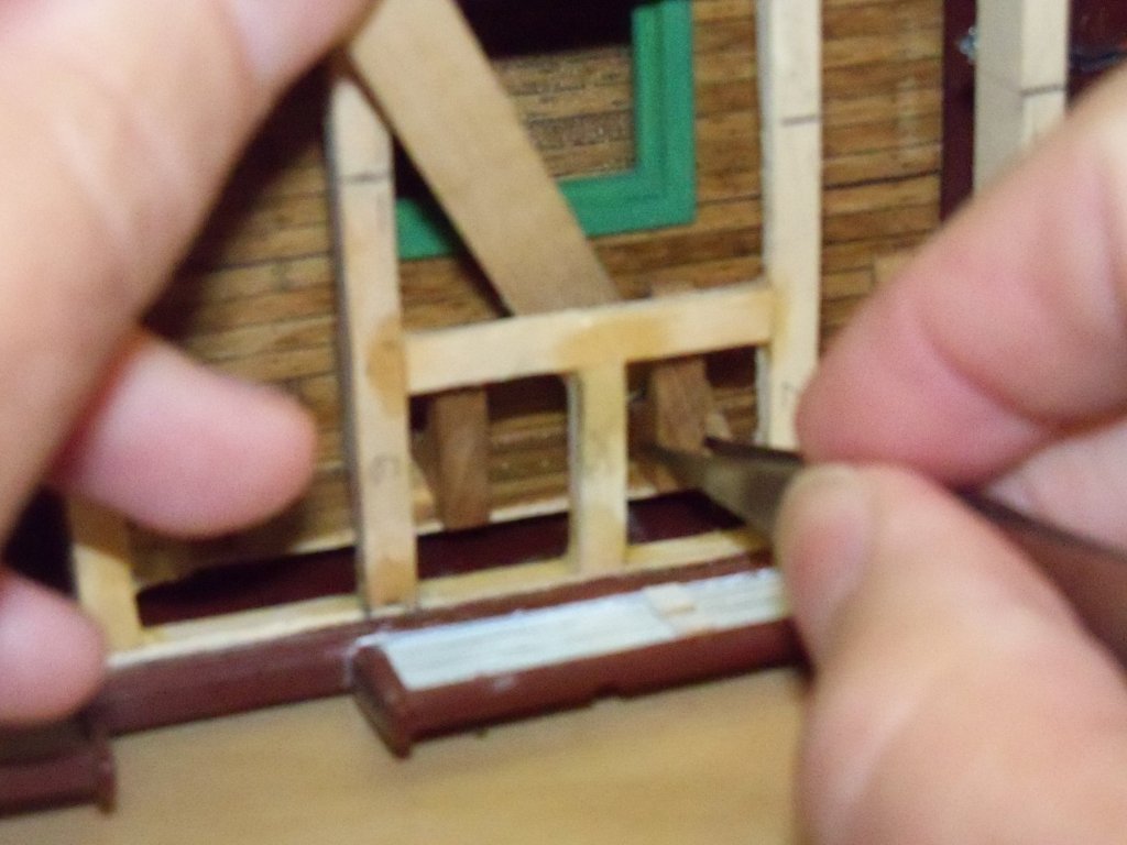
The knees alongside the hatch were the most difficult as I needed one hand to set them in place and the other hand with a stick held at an odd angle to hold them against the wall and the other knee as shown below until the glue could take hold. Using medium CA was definitely the way to go here, as just a couple small dabs were needed and I didn’t need to hold them in place for very long.
This is the status of my ship right now.

I’m thinking that installing the deck will be the next phase to tackle. There are some things to take care of first, namely some things that have to pass thru the deck itself that won’t be accessible once the deck is fastened down. The rudder shaft, the hawse pipes and the anchor chain for example.
-
Kortes, you seem to have a very high level of skill in just about every phase of ship modeling with very limited tools and materials. You have a lot of ingenuity in using everything from paper clips and shoestrings to staples and rubber bands to clamp some very uniquely shaped parts. At the same time, you seem able to convert everyday products like nails and plastic strips into just about any part that you need for your project.
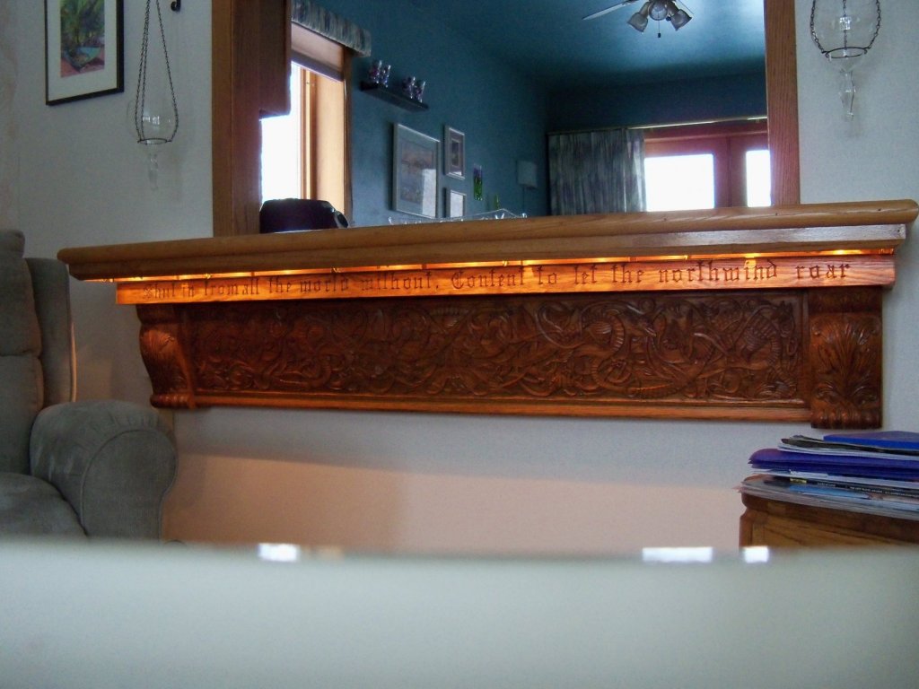
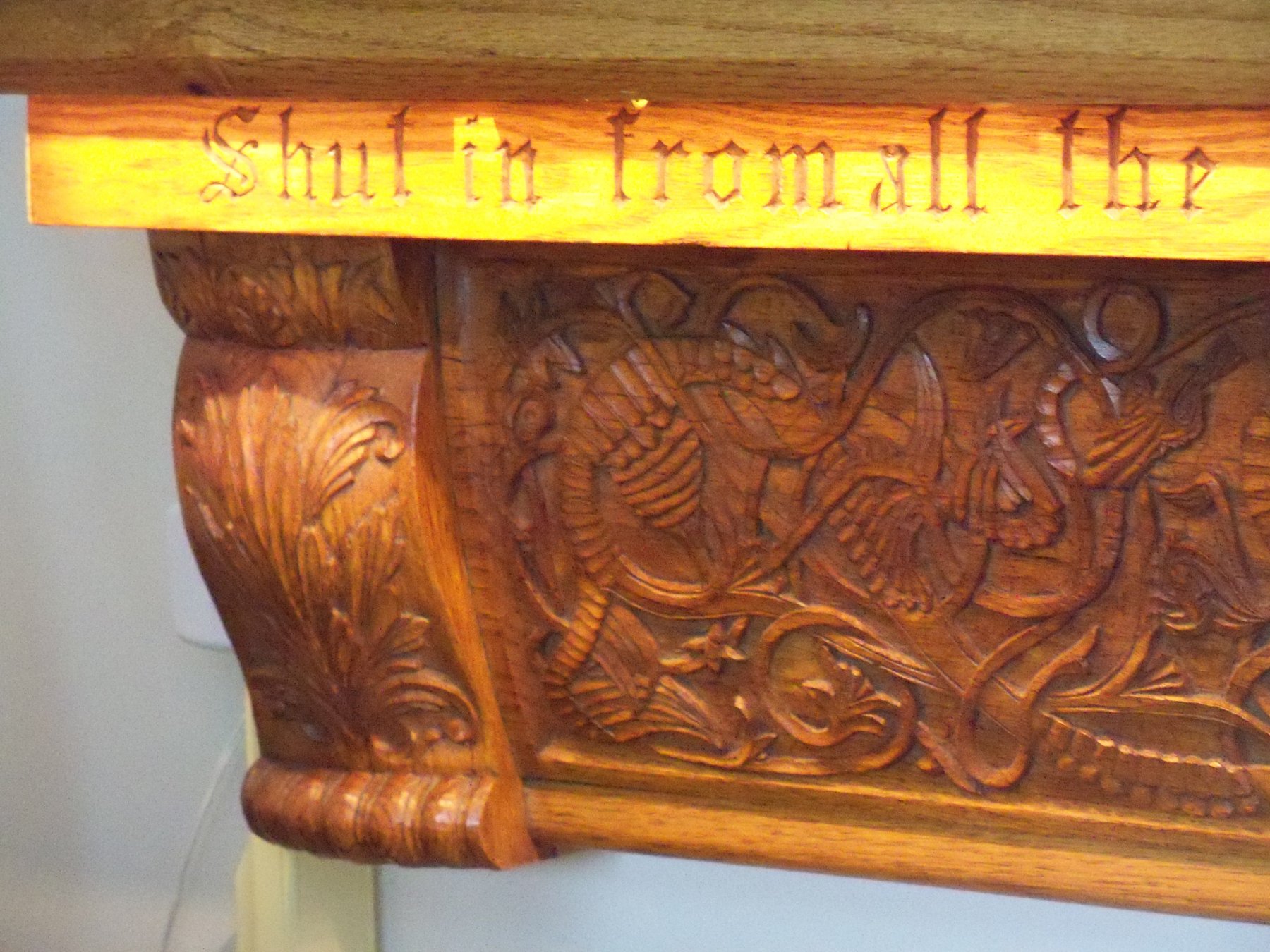
You remind me a lot of my paternal grandfather, who back in the Depression era of the 30’s, could make or modify his own tools, work with whatever materials were at hand, was self-taught in wood carving, and could turn it all into some unique pieces of sculpture, furniture, or in some cases both. Here is just one case in point. This was a mantle he made for his fireplace back in 1932 that I inherited from him and remounted as a support for a pass-thru countertop in our home.

I, (and probably my grandfather if he was still around), would just like to salute you for your outstanding workmanship on this very unique and complex project of yours!
 I'm sure that many of our fellow MSW members would agree with me on that!
-
I just caught on to your build log and am impressed with the quality of your workmanship. Your model looks like more like a piece of furniture than a real ship, but then some of us prefer that over the rough used look. To each his own I guess. I for one, really appreciate your presentation. Keep up your fine work and I will follow from here.
- CaptainSteve and Sea Hoss
-
2
-
I just spent several long hours engrossed in searching out as much of the history of this ship as I could get my hands on within the limits of the internet and my small maritime library. What I found was quite interesting and I think that knowing the ships life story just makes me more determined to make an accurate replica of her. While I’m sure this is hardly her whole story, it’s as complete as I could come up with in such a short time. What follows is a short narration of what I discovered, from her launch to well after her tragic end.
The Wanderer was built in 1877-78 in the shipyard of J. H. Holmes & Sons in Mattasoisett Ma. for the owners Gifford & Cummings of New Bedford, Ma. She had the distinction of being not only the last whaler, but also the last ship of any kind to be built there.
The Wanderer had the last of her restraining blocks removed and she slipped off the ways on April 16, 1878. She was then taken just a few miles to the shipyards in New Bedford for her final fitting out for sea rigged as a bark, also notably, the last ship to sail from there. She measured 116’ stem to stern with another 50’ of bowsprit. Her beam measured 27’-8” with a draft of 15’-8”. From her decks the mainmast rose 125’.
On June 4, 1878 she set sail from New Bedford on her first four year whaling voyage which took her to San Francisco Ca. Changing her registry to that city, she then sailed from there on August 29, 1882 to hunt the whaling grounds in the North Pacific and Arctic oceans.
In February of 1903 the Wanderer left San Francisco on another four year whaling voyage that saw her return to New Bedford. In the following 20 years she would make 11 more whaling voyages. She also made a short side trip as a Hollywood stand-in for the Charles W. Morgan in the silent movie “Down to the Sea in Ships” filmed in 1921-22.
For her part she was rigged to match the Morgan and was filmed in all the scenes shot at sea. At the time the Morgan was deemed unseaworthy and was only used for the scenes in port, thus a star was sort of born. The film never gained much acclaim as a film, but the Wanderer for her part gave a credible performance as a whaling ship. While watching the film, I found the story and the acting to be rather poor, but the actual act of hunting the whales was true to form.
There was another film with the same title made in 1949 staring Lionel Barrymore, Richard Widmark, and Dean Stockwell. This version bared little resemblance to the first, but the acting and story line were far superior. However, both films showed a good view of life on a whaling ship and allowed me some glimpses of the ships’ details that should help me to improve on the model.
Getting back to my ships history, after WWI the price of sperm whale oil had dropped drastically as crude oil drilling on land became a more economical source. Although some nations still hunt whales for food, hunting them for oil became more and more of a poor investment.
As somewhat of a last gasp however, the Wanderer was once again fitted out in the summer of 1924 for her last whaling voyage. What followed was the end of a proud ship, and at the same time signaled the death of the American whale oil industry.
The Wanderer was anchored just west of the Mishaum Ledge Bell Buoy on August 24, 1924 waiting for more favorable winds, when a large tropical storm system that was coming up the east coast came through Cape Cod. The ship was hit from the NE with extremely heavy squalls and gale force winds. Around 10 AM on the 25th, her main anchor chain broke, and despite dropping a second anchor, she was driven by the winds across the bay. She was flung high up on the rocks of the Middle Ground Shoals off of Cuttyhunk Island.
Seven members of her crew were picked up the same day by the Cuttyhunk Life Saving Station. A second boat, with eight men aboard reached the Sow and Pigs lightship the following day and was rescued by the lifesaving crew there.
So much for the crew, but the ship was considered a total loss at this point and salvagers began to work recovering what they could. The remaining boats, sails, whaling gear, the figurehead and the mailbox were all removed, but a second storm blew in on September 30 and completed the destruction of the ship’s hull, washing her rudder ashore about a quarter mile down the beach.
Eventually a few other components of the ship were recovered including her mizzenmast which would serve as a flag pole in Mattasoisett Shipyard Park until being struck by a bolt of lightning in 1964. It now hangs in the Mattasoisett Historical Society building.
Just recently on January 16, 2013, another component became noteworthy. A 34’ section of the salvaged foremast from the Wanderer was donated to the museum from the New Bedford Whaling Museum after concerns over its preservation came up. During a renovation in New Bedford of their museum back in 2010, it had been moved outdoors.
Since the artifact was too long to fit in the small museum building in Mattasoisett however, the Historical Society built a shelter to display it and protect it from the weather.
So ends my tale of the last American sailing whaler to set out on a whaling voyage, short as it was. Now the Charles W. Morgan has outlived its theatrical stand-in to become the last surviving American whaler, but no more famous than the Wanderer in my mind.
- JesseLee, Fright and popeye the sailor
-
3
-
On 1/14/2019 at 4:51 PM, DORIS said:
Here are some pics:
Those are some great underwater photos. The water looks quite clear. All of my own experience with snorkeling was in the waters of western Maui. When the sun was shining on the water the photos would really shine, but when the clouds covered the sun most of my photos came out rather dull. Eventually I rented an underwater camera equipped with a flash and was happier with those.
I found it surprising that even when snorkeling along the shoreline in water less than 2 feet deep the water was still teaming with lots of small colorful fish. It's one of the activities that I'll always miss the most about Maui now that I'm wheelchair bound and will probably never get to do it again. However, I'm very glad that I took those trips while I was still able to do so and still have the memories and in some cases the photos to bring them back.
-
Careful with that whiskey Froggyman, cause you know too much of it mixed with sharp utensils often leads to visits to the ER. On the other hand it can smooth out the rough spots in your builds.
") Personally, I prefer a nice cold bottle of Big Wave Ale from Kona Brewing Company, lets me wet my whistle while I work and I can still see straight.
Personally, I prefer a nice cold bottle of Big Wave Ale from Kona Brewing Company, lets me wet my whistle while I work and I can still see straight.
- thibaultron and mtaylor
-
2
-
While trying to determine what size to make my oil barrels for the Wanderer, I found that apparently among some historians, there was a lot of disagreement on what size the barrels were for oil on these ships. I found that 31.5, 35, and 42 gallon sizes were most common, but some barrels were 750 gallons or more.
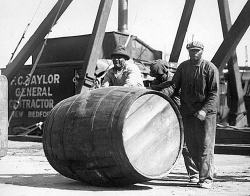
For example, check out the size of this barrel in this old photo (shown in Google under the heading whale oil barrels by Spinner Publications #ST 00841) below that three dock workers in New Bedford were trying to move around.
 It looks to be over 400 gallons or so as near as I can estimate. It must have been a royal pain trying to muscle this thing around below decks, and this isn’t even one of the really big ones!
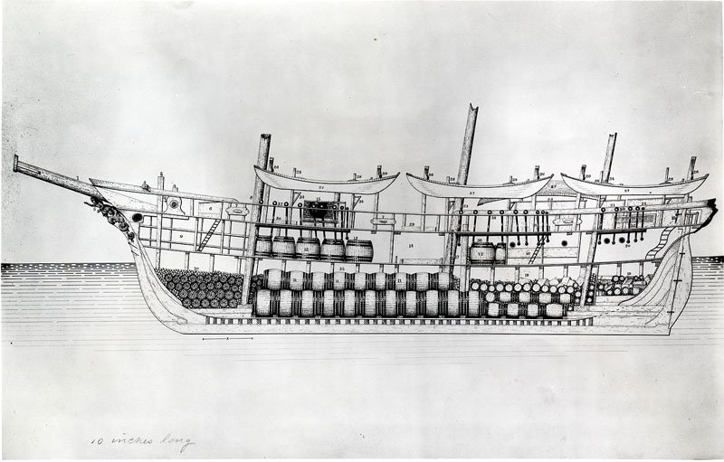
Further searching through google revealed that apparently the barrels actually came in many different sizes as shown below in an illustration diagram included in an article that I came across written by Sara Kay Bierle in a posting of gazette665.com. If you look closely, you can see at least six or seven different sizes and that in the area of the bow, the knocked down barrel components were stored until they were needed.
Ship’s Layout
This diagram from an 1887 publication shows an example of the interior of a whale ship.
Logically speaking, I guess that that does make some sense, since they were trying to get as much oil as possible below decks. In the complex shape of the inside of the hull some areas could accommodate the larger barrels, but then again, the tighter areas couldn’t be efficiently filled unless the barrels were smaller. Many barrels had elongated shapes to fit into some of the tighter spaces, and in some cases the ships coopers were even known to have made custom sized barrels as needed.
As whalers owners were paid by the number of barrels of oil she could hold, it leads to some confusion as to exactly how much oil this would have been. I suppose that when the final tally was taken in port, the officials there would measure each barrel, calculate its volume and multiply by the number of similar barrels.
In some of the articles that I came across, buyers would pay the ships owners by the number of 31.5 gallon barrels that this converted to. Seems to me that just converting to the number of gallons and paying so much per gallon would have been simpler, but who knows for sure. So, I guess that as far as I’m concerned, I'll just make a few different sizes for my Wanderer.
By the way, during my search for oil barrel sizes, I came across some photos taken below decks of the C.W. Morgan that did show my reinforcing knees between the inner deck and the inner hull. However, in addition to those knees and right beside each one of them was an additional knee between the inner hull and the beams for the upper deck!
So, now it looks like I need to make another set of knees. Good thing I found this out prior to attaching the deck! I think that I may have cast a few choice phrases about while trying to squeeze them into place somehow.

There were also quite a few more bolts in each one than the number that I put in, but trying to add them now to the ones that I have already installed might not be feasible. I think that I may try to see just how hard they are to remove and put in more bolts, but otherwise I’ll just stick to two bolts in each one.
So, for now it looks like I’ll just have to get back to making more knees for a while.
- gieb8688, Cathead, popeye the sailor and 1 other
-
4
-
Well Jesse, that's still no small task that you've finished there. After all, as they say, our hobby is not a race to finish, but rather something to enjoy while it lasts. Adding the spar accessories off ship will make the rigging simpler and actually faster anyway.
Keep it up, you're doing a fine job.
-
Still not sure about the knees, but on to something else for now.
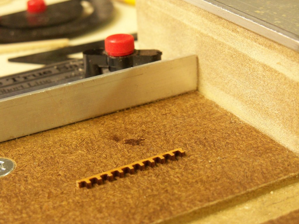
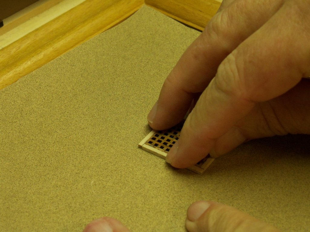
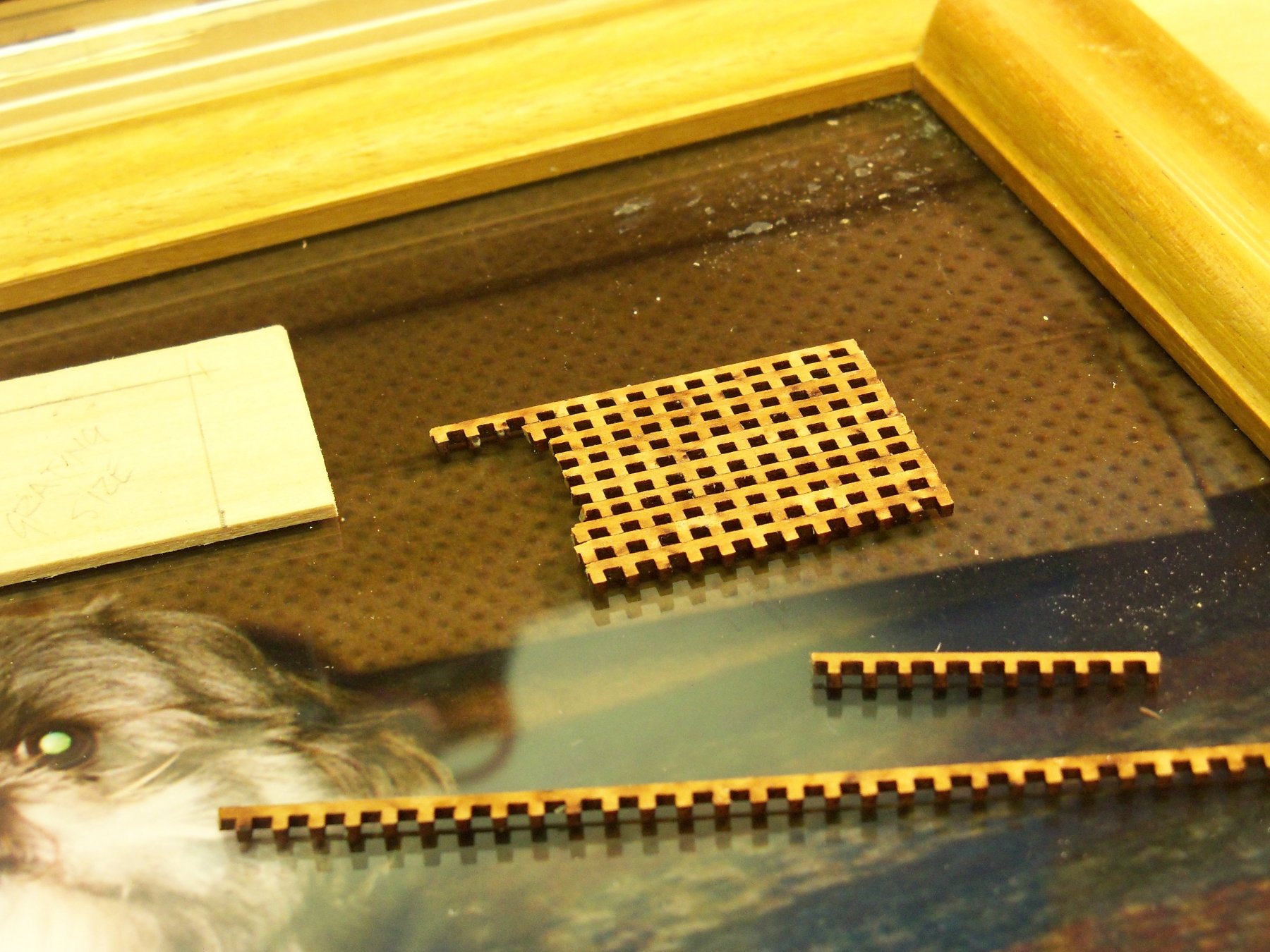
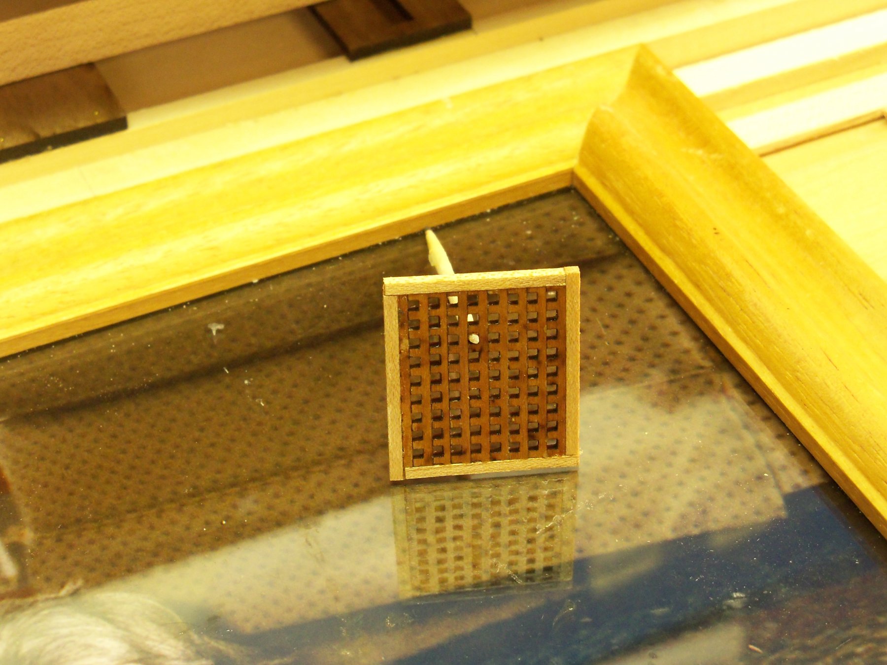
One reason that I decided to make a grating for the lower hatch was that my kit for the MS Phantom had precut grating strips that, @ 1:96 scale, were overlarge for that kit. Since I was working now @ 1:87 scale, I thought they would be a little closer to scale size for this ship. (Maybe? Maybe not?)

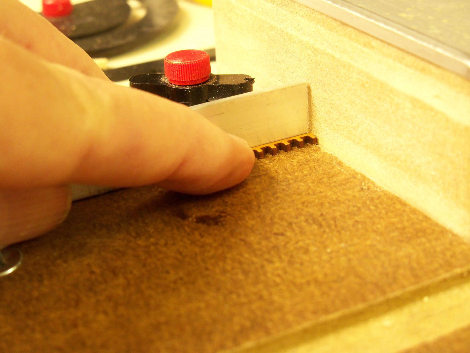
At any rate, I wanted to try making some grating anyway. These were intended to be assembled by overlapping, but I thought that the thickness would still look too much out of scale. Cutting off some lengths close to the required finished size, I took them once again to my square sanding jig and sanded one end square. As the nubs were very fragile, I was careful to only sand toward the guide or risk snapping them off!

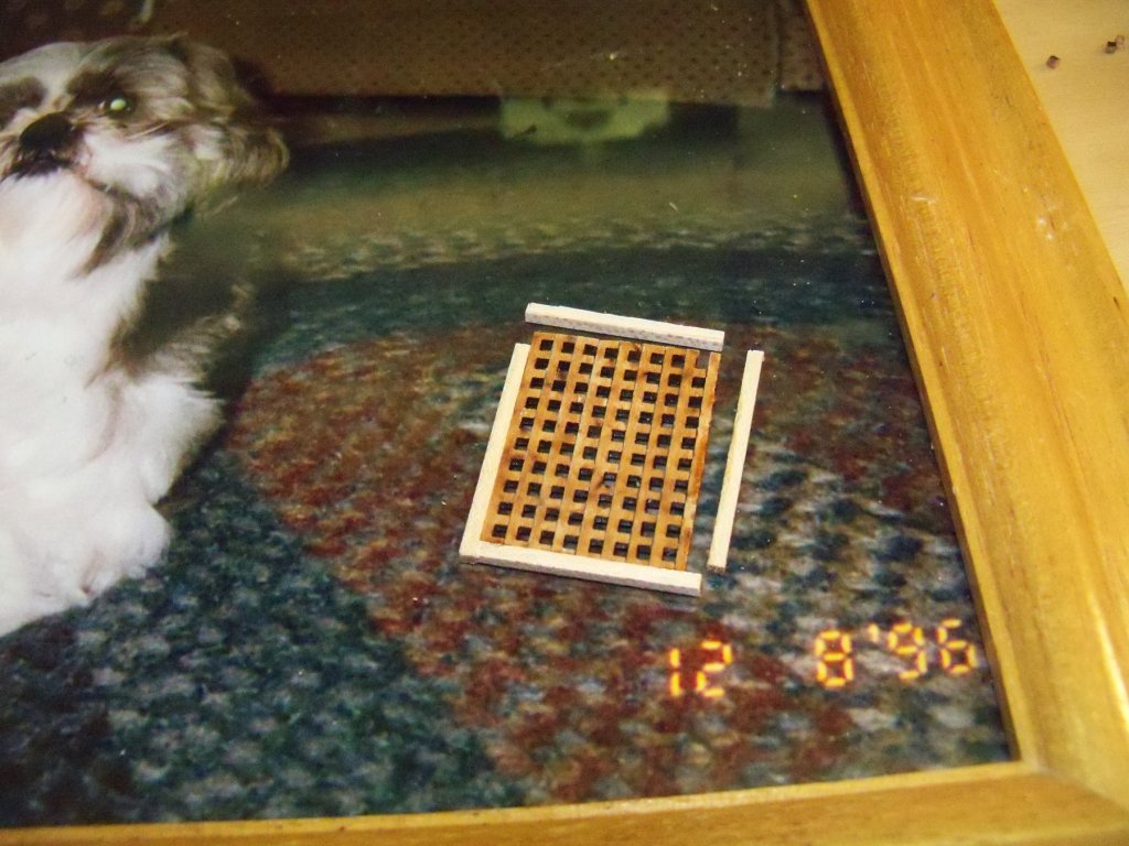
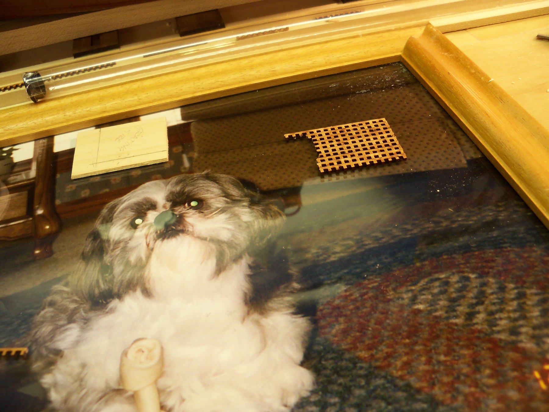
Needing a surface that was both flat and that my carpenters glue would not adhere to, I found a framed picture with glass of our favorite neighborhood dog Chester. (He passed several years ago, but I didn’t think that he would object to helping me out.) Anyway, the frame corner was square so it would also serve as an assembly jig.

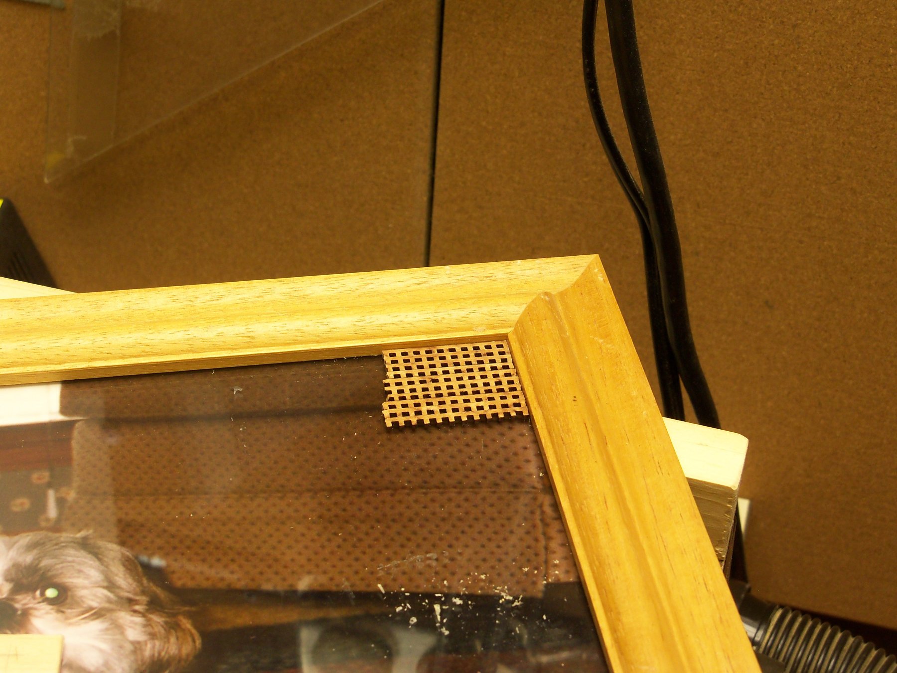
I took one strip at a time, and with a tooth pick applied just a small dab of the glue to each of the nubs. Then they were butted into the corner and against each other briefly to let the glue grab hold.
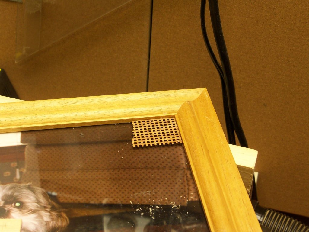
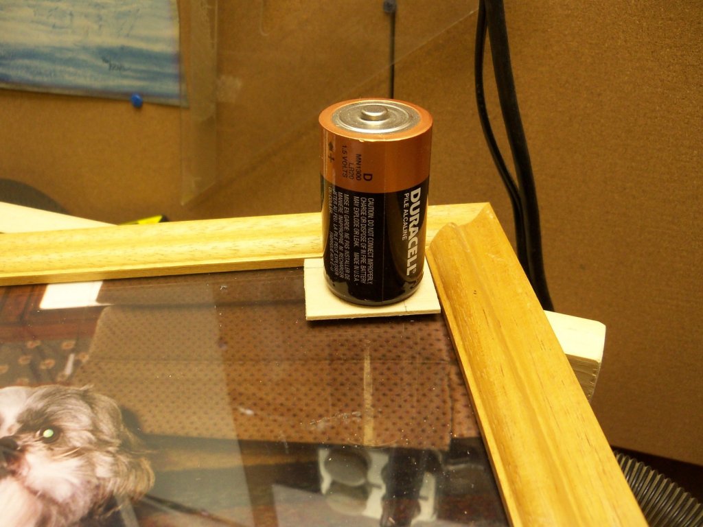
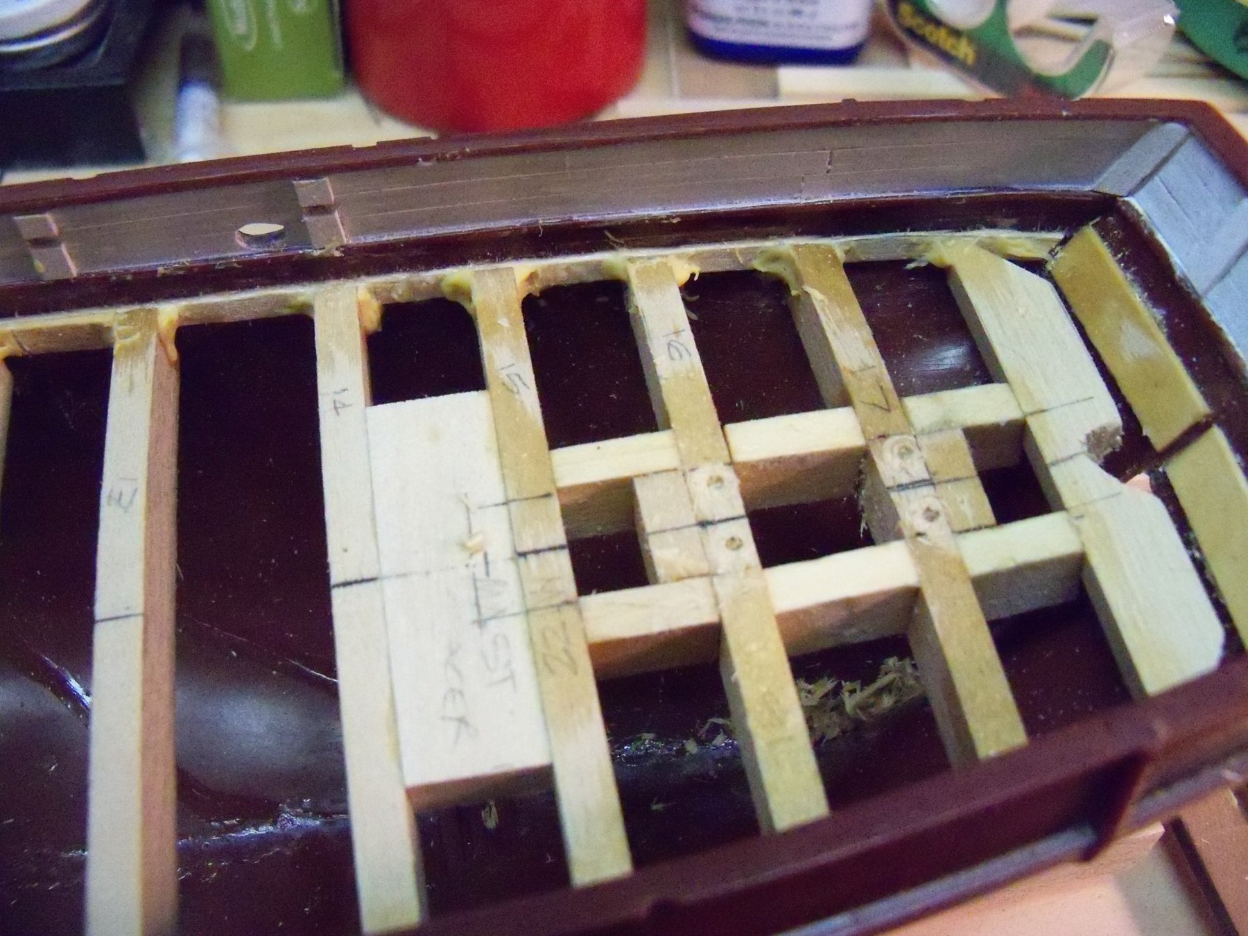
This was repeated for each piece until the assembly was wide enough for the size of my grating. I took a scrap of basswood with wax paper on the bottom, laid it on top of the grating blank with a size D battery on top to make sure it remained flat, and let it dry overnight.
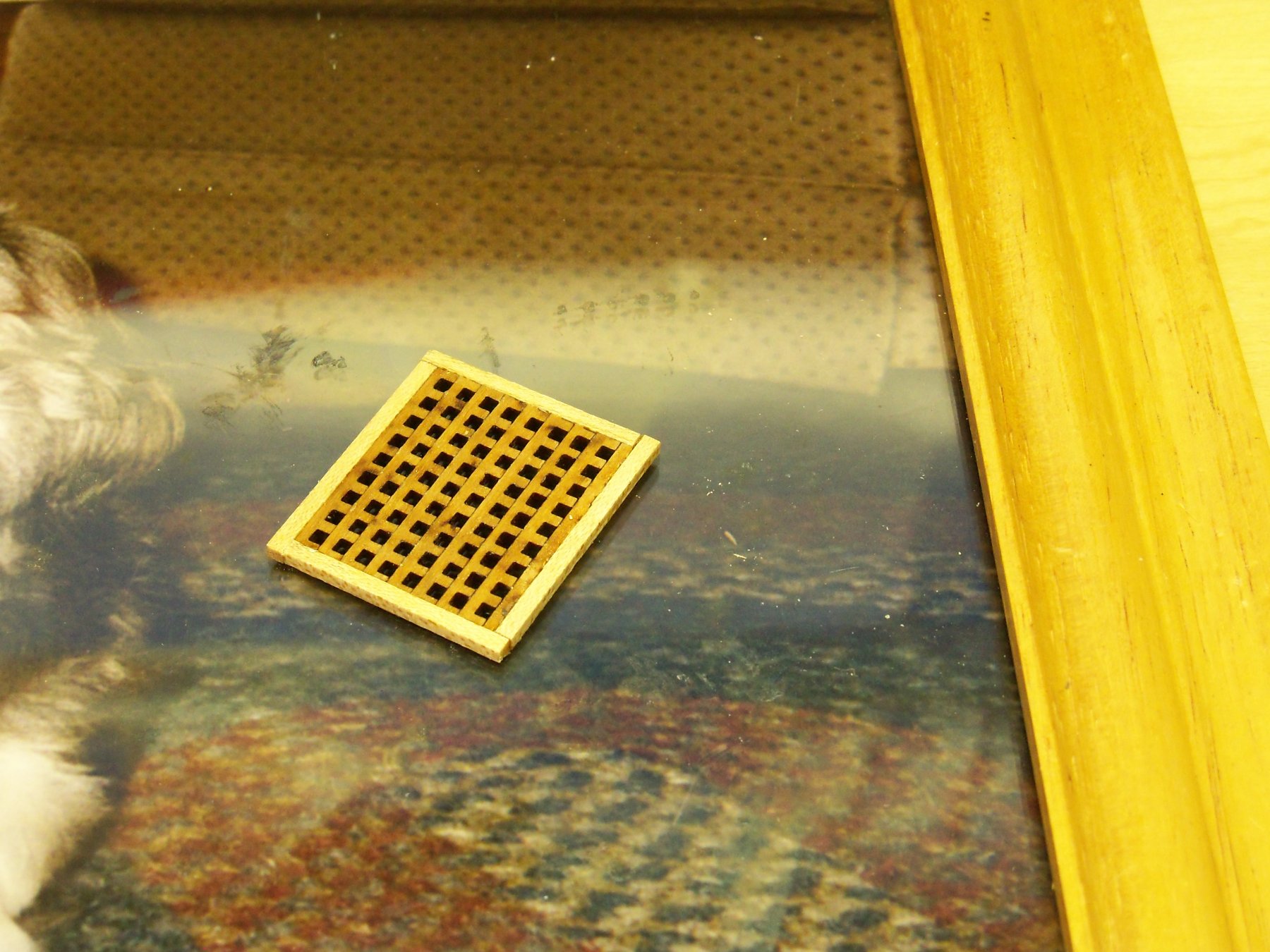
While this method allowed me to have enough material to make the grating and make the thickness more to scale, I was thinking that those minuscule dabs of glue wouldn’t be sufficient to hold it together. As it turned out, I was right, the assembly was very weak and kept separating when sanded. I applied some medium CA to the backside of the joints which helped some, but I decided to add a frame around the grating to add some more strength to it. I ripped down some 1/32” strips of 1/32" maple for this frame. The grating still needed some downsizing on the long dimension, so I cut the frame pieces so the ends would overlap and glued two pieces to one corner with more CA and put aside to set overnight.
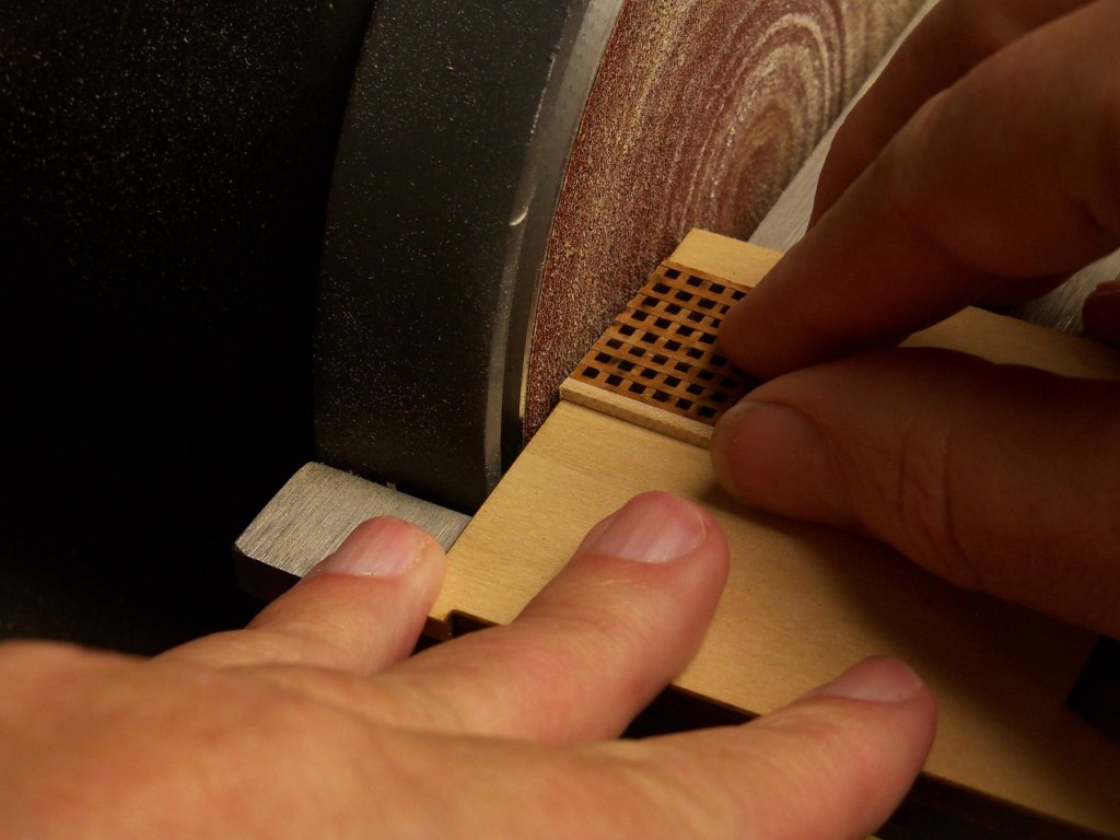
Next, I took the assembly to my disc sander and very carefully trimmed the long end of the grating down to match the length of the long frame piece.
Here, the remaining frame pieces were glued on with AC and left to set.

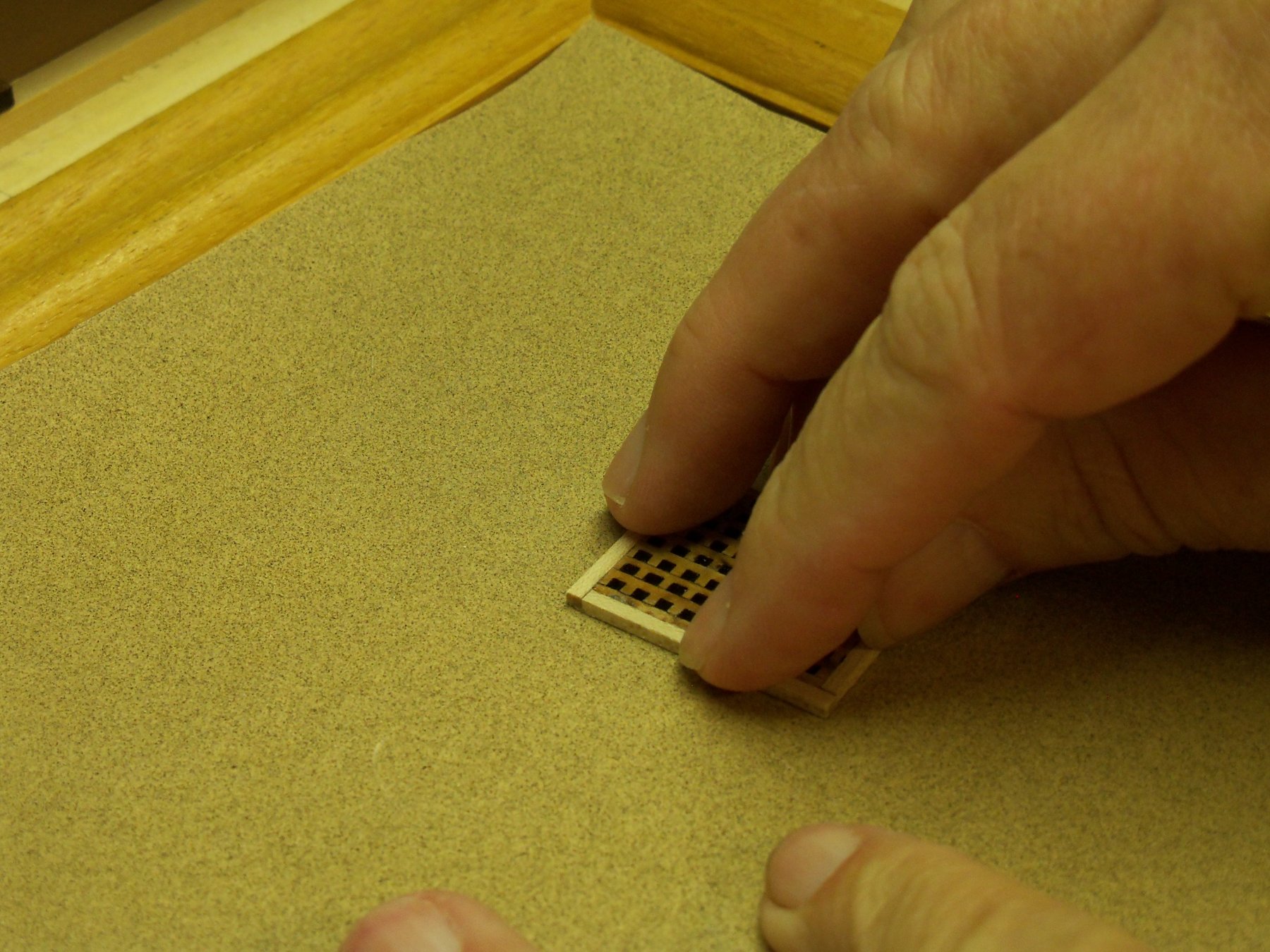
Once it was dry, I sanded the faces of the completed grating flat by hand, as I still had my doubts about its strength.
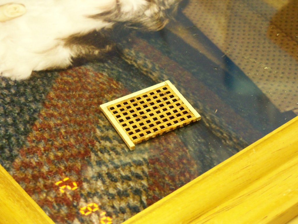
I decided not to stain the grating frame, so just two coats of poly were applied for my finish to leave a little contrast between the grating and the frame.

I plan to leave the grating off to the side of the hatch as the ship will be displayed in the act of loading a cask of oil down into the hold. So, now to figure out what comes up next.
-
What did you use for a punch?
- Keith Black, thibaultron and mtaylor
-
3
-
On 12/3/2018 at 2:28 PM, BETAQDAVE said:
This did however bring up a question about the inner deck. I assumed that the inside deck had a matching hatch opening going into the bottom of the hull to store the casks of oil.
My question is: did this inner hatch have a combing with hatch covers, a grating, or was it just left open?
After much searching I managed to find this sketch in my copy of Whale Ships and Whaling by Albert C. Church on detail # 158 that showed a combing for the lower hatch, although still no cover was evident. If you look closely, the sketch also shows a bolted knee that I also incorporated into my lower deck.
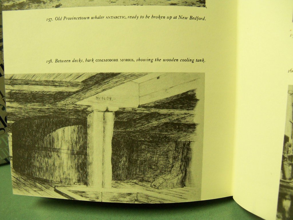
However, looking in numerous build logs since, I am at a loss as to what function this knee serves. Every POF log with interior details that I came across show knees supporting the decks above rather than as shown in the sketch. Does anyone know its function or have I included a detail that does not really apply to the Wanderer, since there was no cooling tank that that I know of below her decks?
-
Outstanding iron work here!
- mtaylor and Keith Black
-
2
-
18 minutes ago, Landlubber Mike said:
I saw you mentioned you build the Wanderer in wood. Do you have a picture of that one?
Sorry Mike, built many years ago, long before using PC's and before I ever even thought of taking pictures. Can't remember who I built it for either.
-
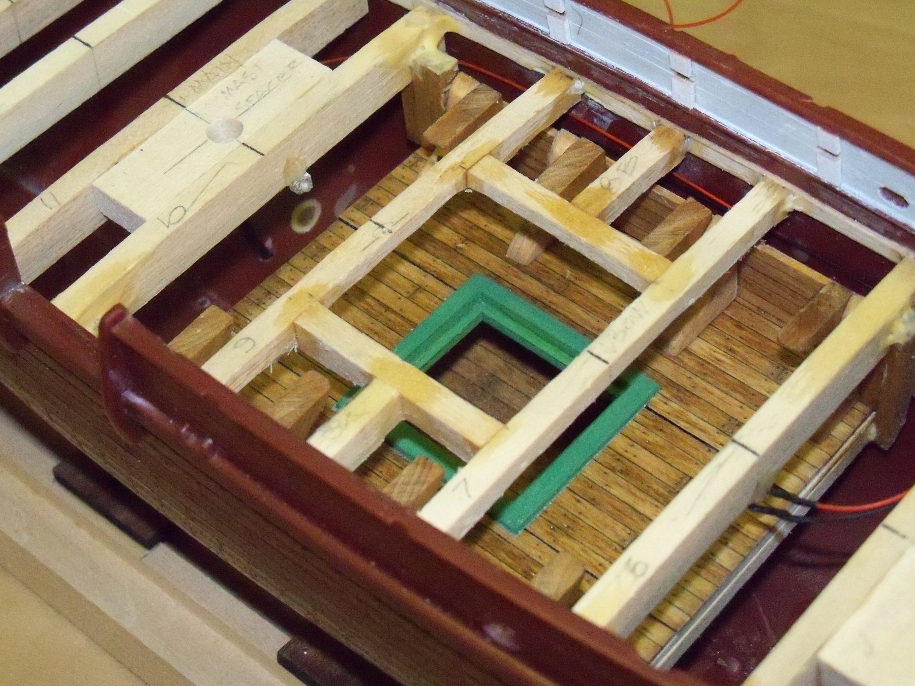
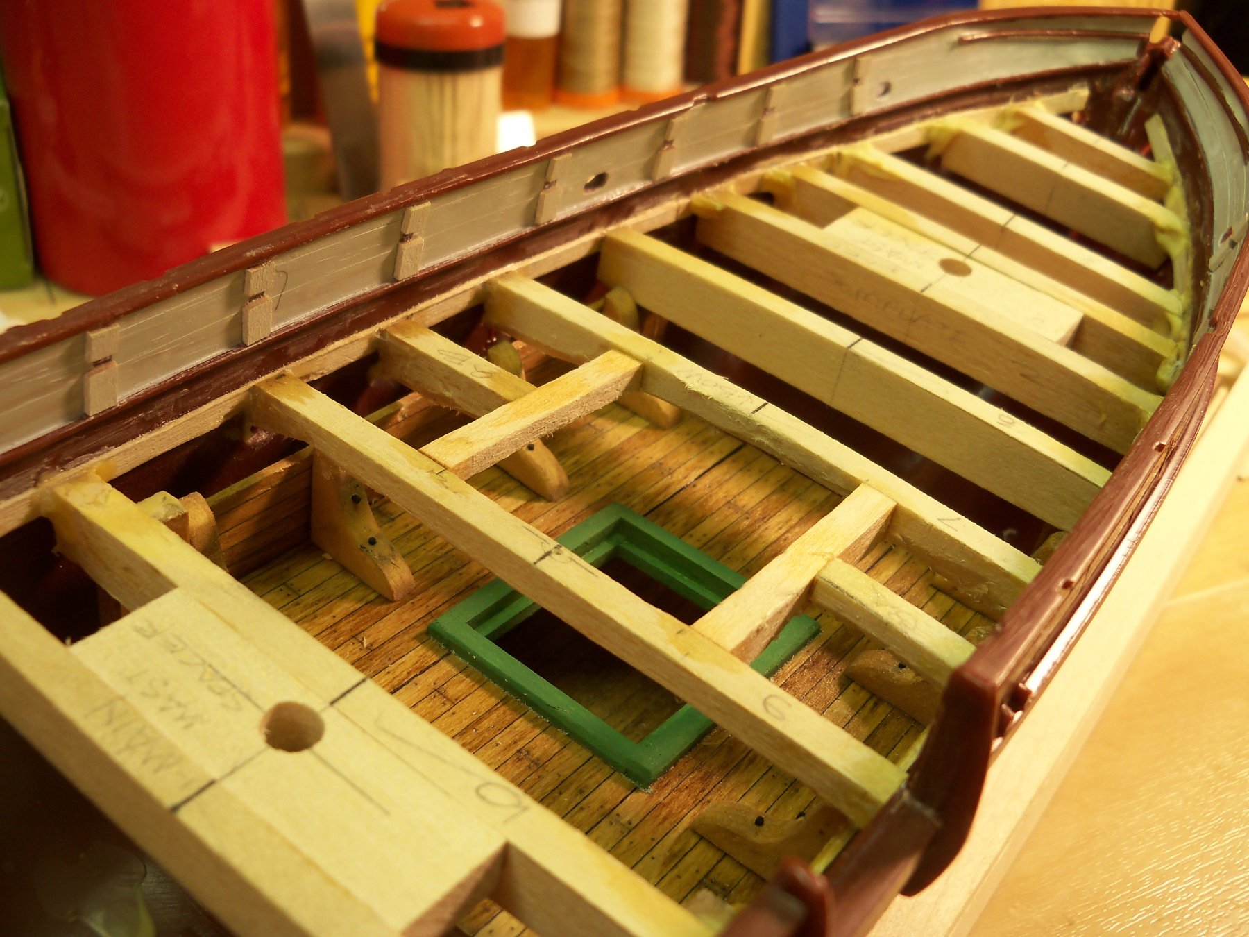
I decided to install two orange flickering LEDs in the lower deck. One to be placed one frame from the hatch toward the bow and the other one frame from the hatch toward the stern. Here you can see that the beams at the hatch have been reduced in depth closer to scale.

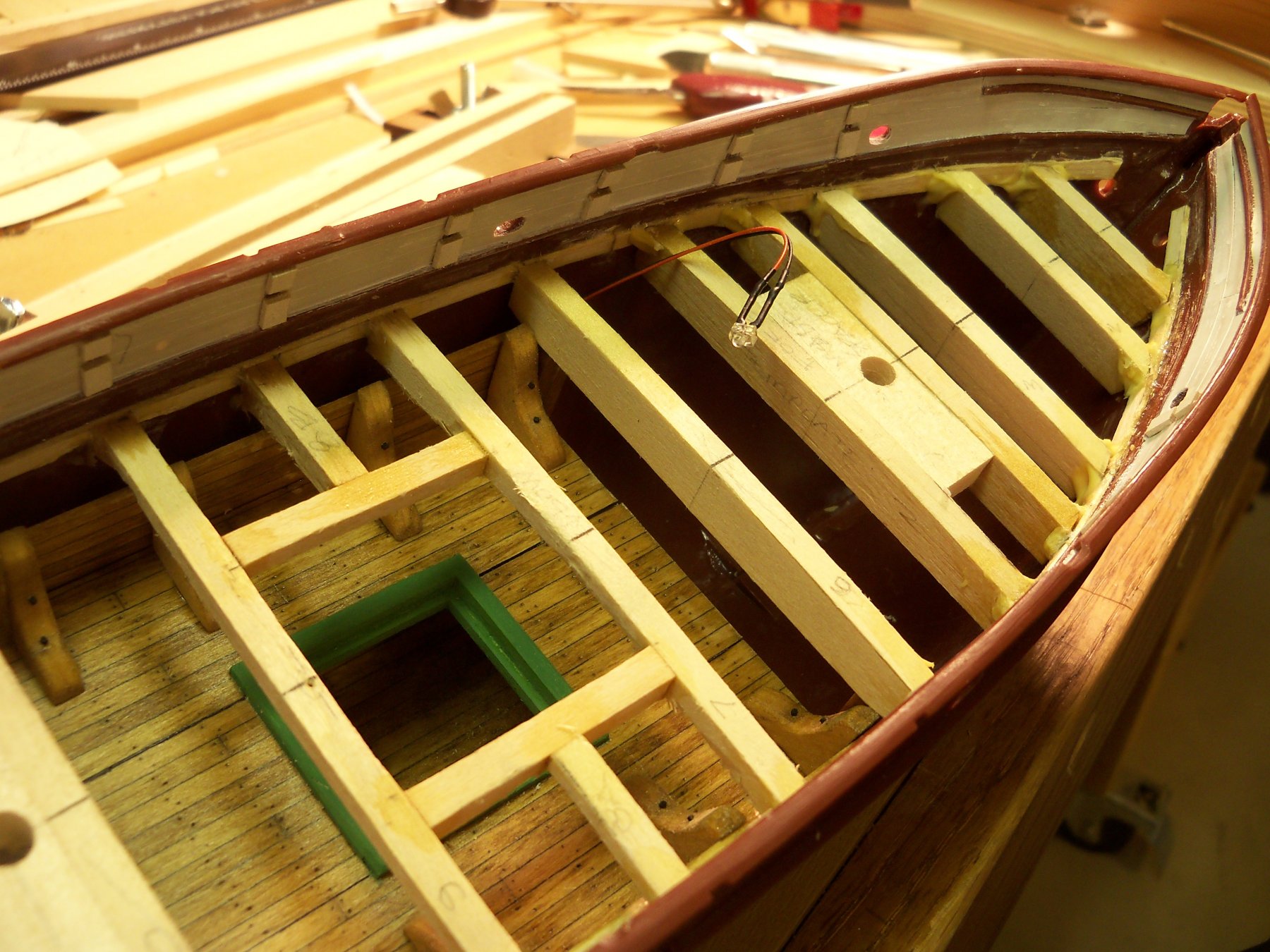
For the one at the bow frame, the wires had to be run between the inner and outer hull sides as shown here.

The one toward the stern was offset slightly to avoid the main mast. The LEDs were glued in place with some medium CA.
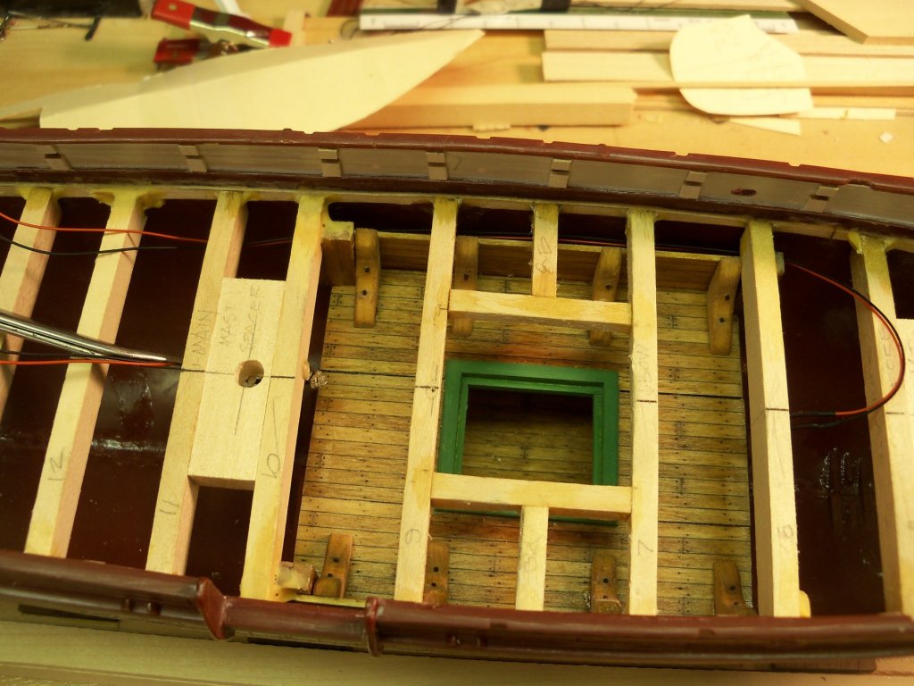
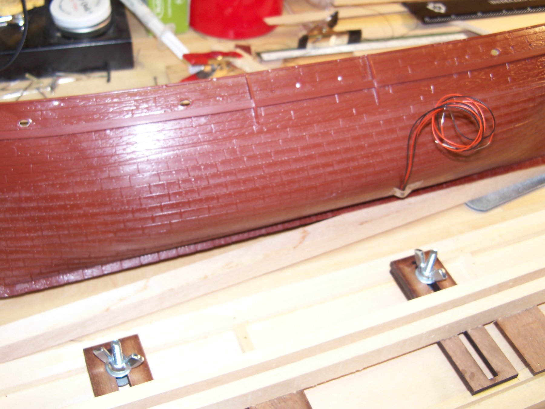
I drilled a 3/32” hole (large enough to pass the four wires with the shrink wrap) in the bottom of the hull on the port side which will be the side of the ship against the wall when displayed and thus less visible. The excess wire was coiled and taped to the hull for now.

-
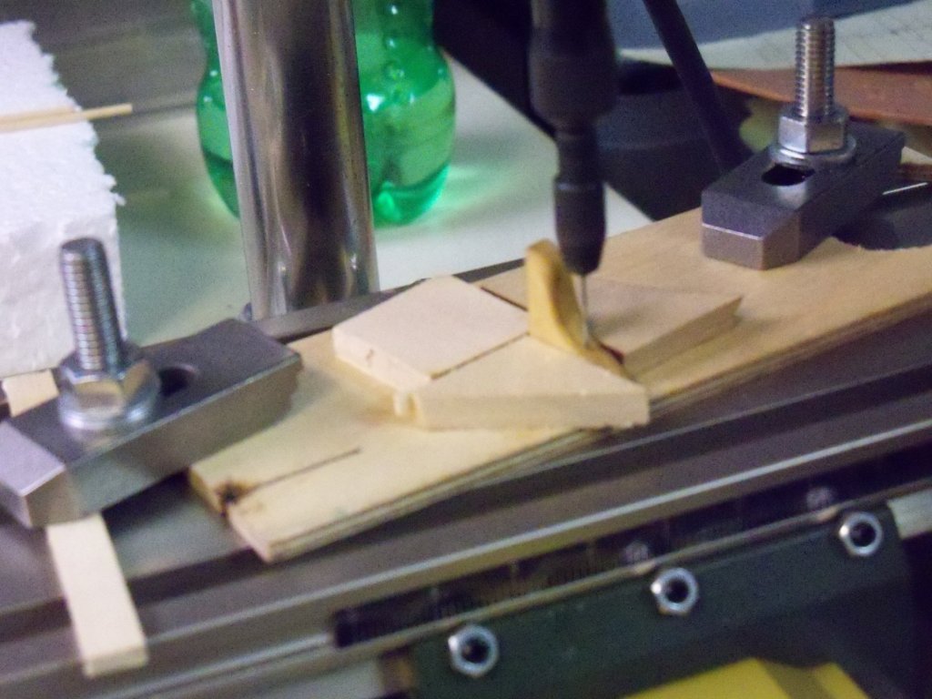
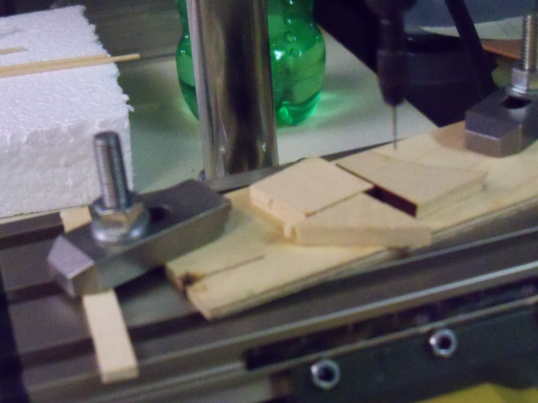
I set up this drilling jig with rubber cemented scraps and mounted it on my Proxxon X-Y table as shown.

The knees were all placed in the jig as shown to place the bolts consistently. I drilled the holes clean through for a .023” x 1/4” steel brad in each leg.
I soaked the brads briefly in a full strength solution of Brass Black and let dry. The brads were then pressed through the legs of the knees.
The brads were slightly too long, but rather than trying to cut them shorter and risk having them disappear, I just put them in my vise to file off the excess.
The knees were then glued in place with some medium CA.
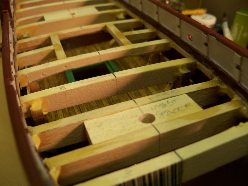
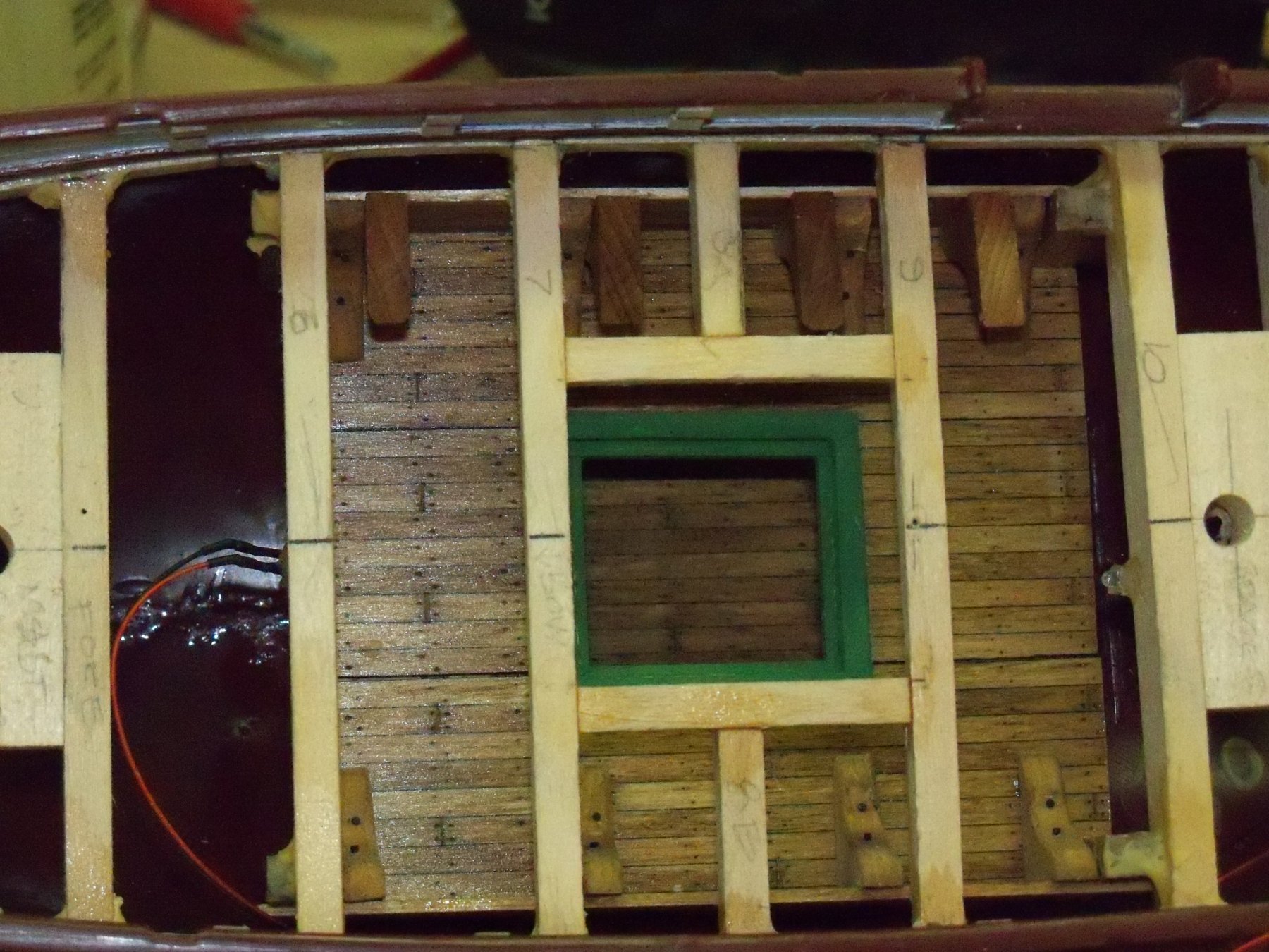
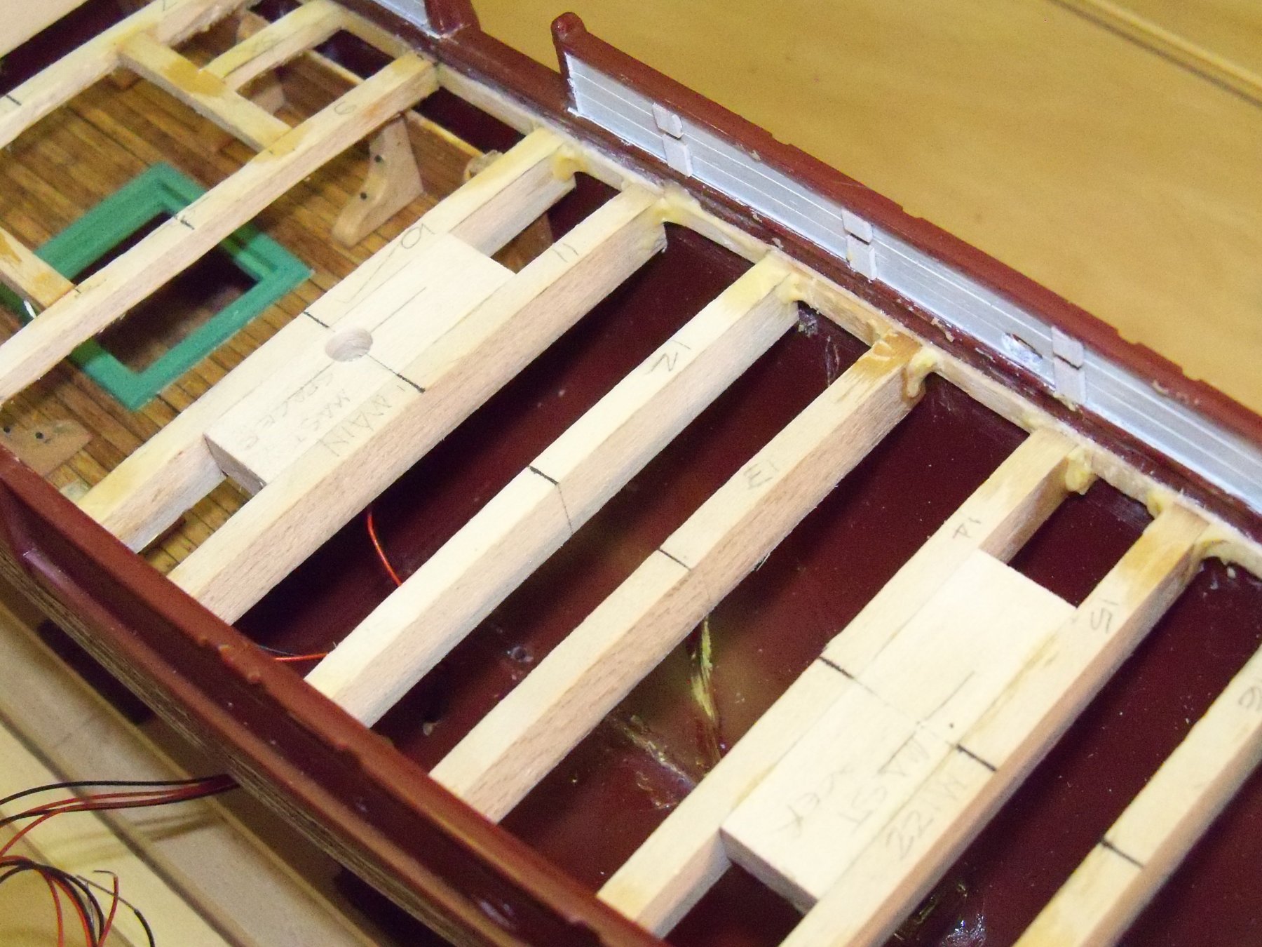
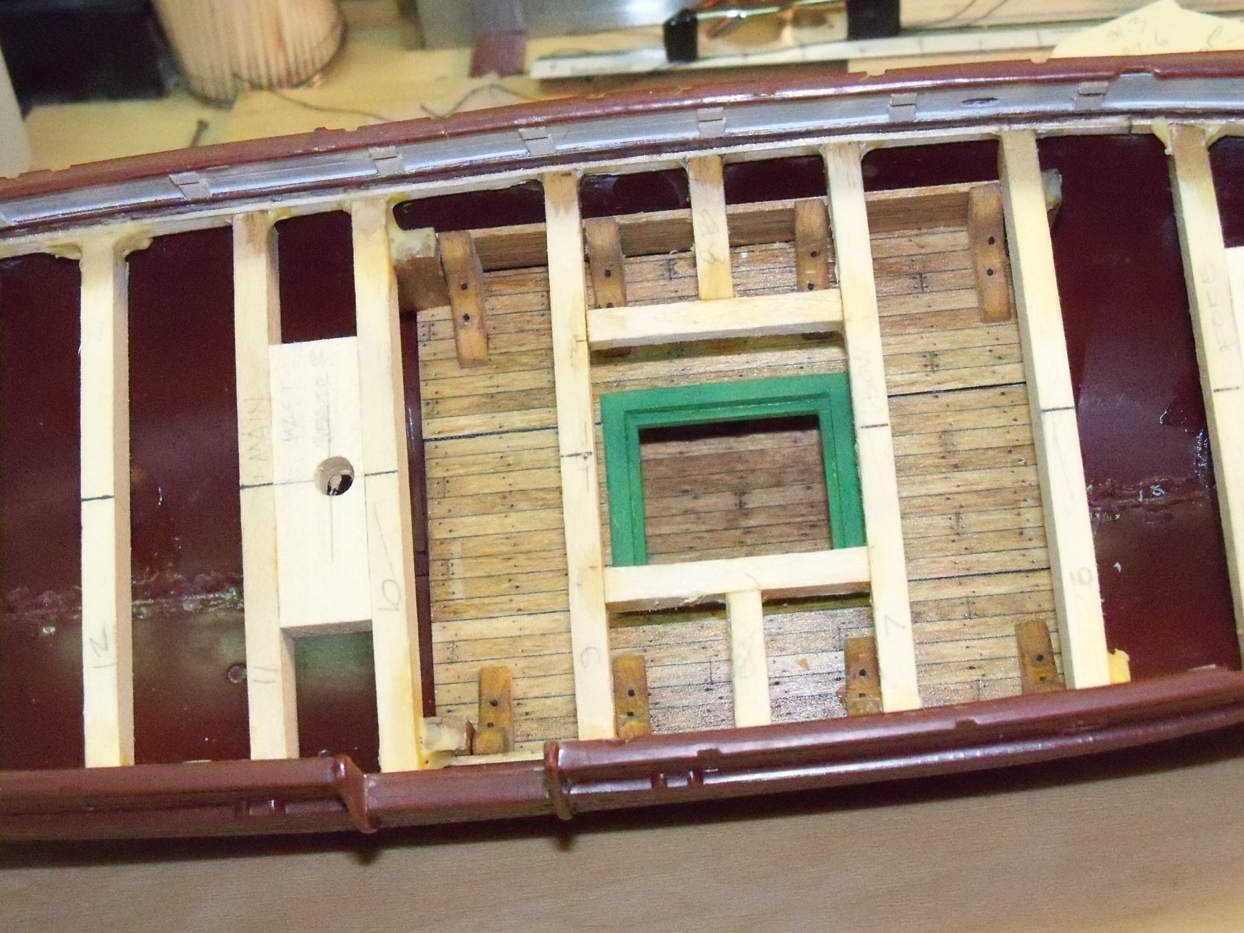
Now I came to realize that the beams had not been sized to scale, as they were originally not going to be visible, but now that this had changed, I thought they needed to be reduced in depth. You will notice that a line was now drawn on the face of the beams here.
With a good deal of trouble they were reduced in place with scalpels and chisels. This also would allow a little more to be visible inside the hull, so I thought overall it was a good thing. Also, in this view from above, you can see that the bottom of the hull would be visible.
Taking another section of the pre-made decking, I marked the treenails and plank ends on this sheet. This was finished the same as done previously. To make this sheet of planking conform to the bottom of the hull, I made numerous shallow cuts in the backside of the sheet parallel to the deck boards. This allowed the sheet to flex enough to match the curve of the hull bottom. The sheet was slid in from the stern, and held in place by using a pencil eraser down through the hatch. I then dribbled some thin CA down alongside the gap in the hull walls that secured it in place.

The next thing to do now is to set up for the LED lighting.
- Rudolf, Cathead, Landlubber Mike and 7 others
-
10
-
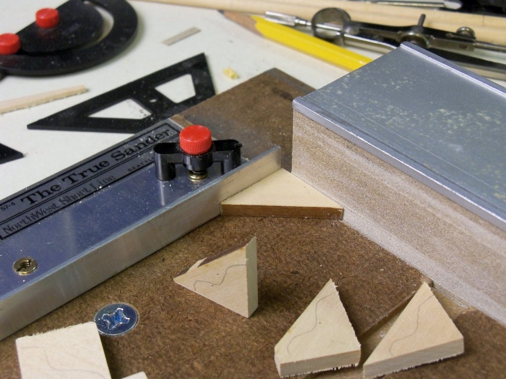
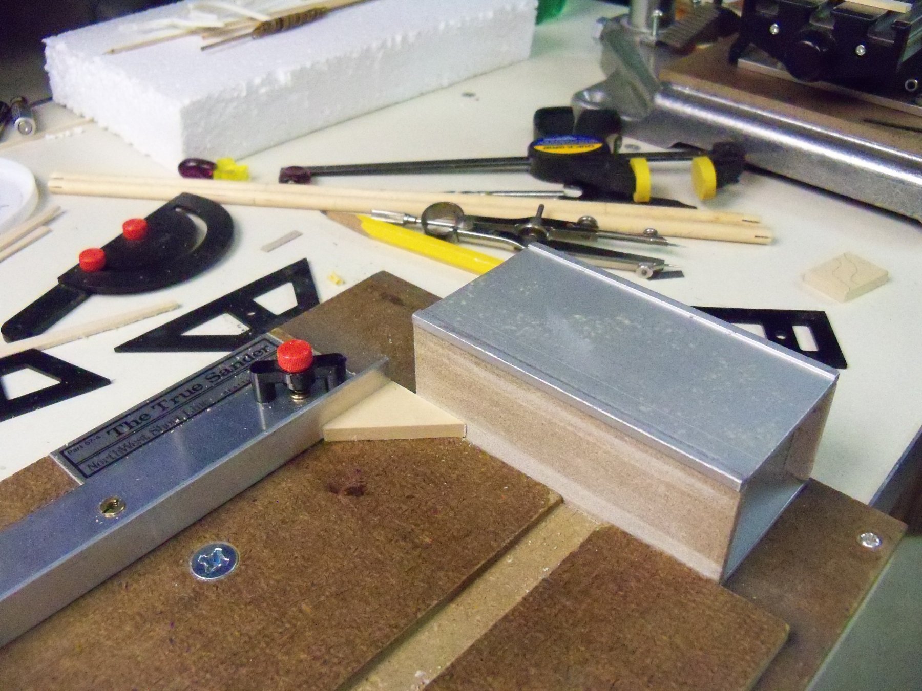
Now here is my knee production method. First off, I took a billet of basswood of the desired thickness and cut triangular pieces with the grain running parallel to the long edge. The remaining edges of these pieces were squared up with my sanding fixture as shown here.

Then I drew a rough outline of the shape of the knee on all eight triangles to help keep track of their orientation, as one leg was longer than the other.
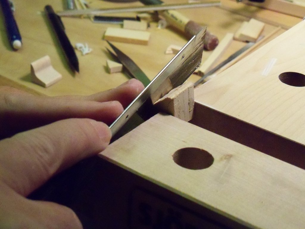
These were grouped in sets of four that were glued up with a thin coating of rubber cement on all the facing surfaces and clamped in place overnight to dry. The next day I drew the pattern on a stiff piece of manila folder and cut it to shape. Holding the pattern in place on the face of the glued up blocks, the pattern was traced onto the top blocks.

I clamped the blocks in my vise and using a small back saw trimmed off the majority of the waste.

The blocks were then sanded close to the outline of the knees on my 2” belt sander being careful keep the block flat on the table.
Now, using several grades of sand paper on sanding sticks the blocks were sanded to their final shape.

Now the blocks were separated from each other with a chisel driven into the glue joint. Even though I only used rubber cement to join them together, they were still held together surprisingly well.

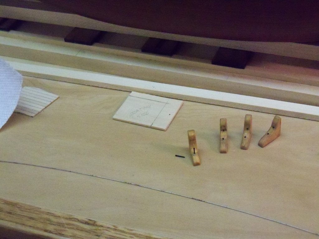
Now I had the eight knees duplicated to the same shape.
Using a fine sanding stick, I eased the exposed edges of all the individual knees.

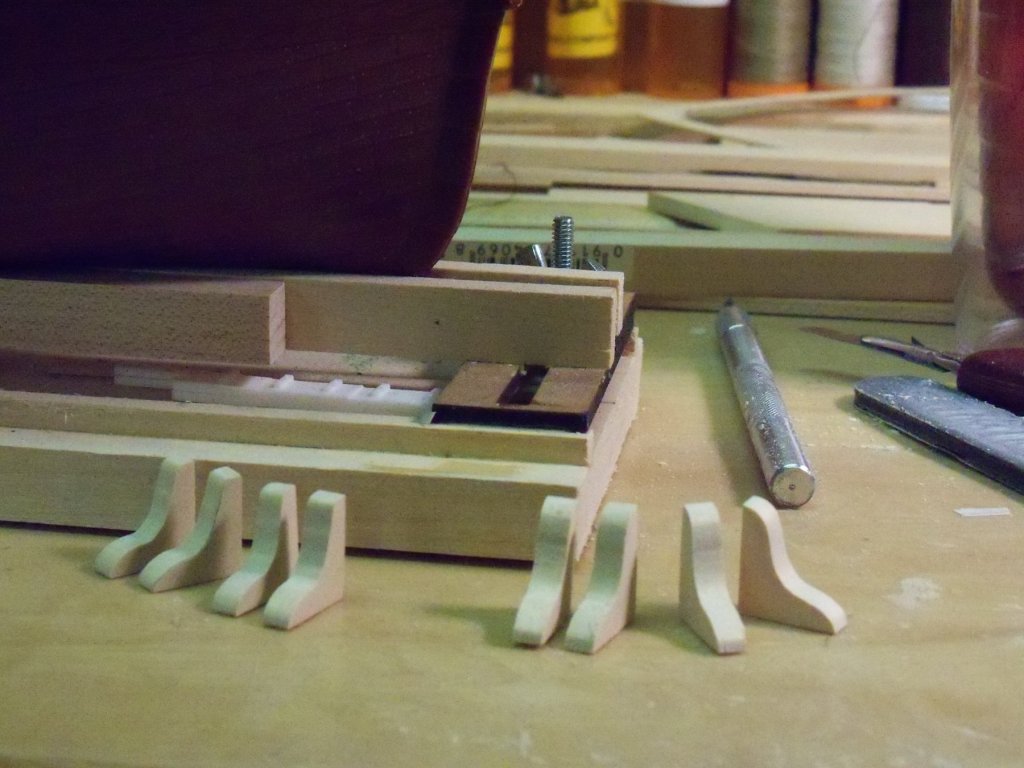
Here are all the knees cut to final shape and given a coat of stain and two coats of polyurethane. I still need to add two bolts to each knee, which will be included in my next posting.
- douglaspbrown, Cathead, gieb8688 and 4 others
-
7


.JPG.d25262ad91c1dd7214472a4a12dc2d1c.JPG)


Greetings and Thanks
in New member Introductions
Posted
Welcome to MSW Dave. Using Legos is not that unusual here at MSW as they are commonly used to square up frames, make casting molds and even for constructing tools like a ropewalk. So don't think that you are strange to think of using them. We build ships out of an almost unlimited number of different materials here including combinations of them. I myself am in the process of making a so called hybrid from a plastic kit by Aurora of the whaling bark Wanderer with components of wood, metal, and even adhesive backed vinyl strips.
Speaking of lego models, look our general nautical discussion heading under the unusual ship model topic. There are several models of note there including: a 64 gun tall ship HMS Persephone (Feb. 3, 2018), the aircraft carrier USS Intrepid, (Nov. 2, 2016), and the Queen Mary (July 11, 2015) to mention just a few individual ships. There is also a pictorial view of a Legoland diorama with several floating ships (Jan. 18, 2015).