allanyed
-
Posts
8,079 -
Joined
-
Last visited
Content Type
Profiles
Forums
Gallery
Events
Everything posted by allanyed
-
I agree with Daniel that fixing the yards makes things easier and it will also provide security over the many years to follow. I use small diameter brass rod as described in The Fully Framed Model volume IV. Most importantly follow Daniel's advice about pre rigging as much as possible on the yards before hanging on the masts. For a LOT of great detail on rigging my two favorites are James Lees' Masting and Rigging and David Antscherl's The Fully Framed Model volume 4 and his sail making supplement. The order of dressing in TFFM is more user friendly for modelers than the OOD in Lees which I believe was that which was done on actual ships. Allan
-
WELCOME TO MSW!!!! Allan
-
 Blacky, I have all of the Ardent (1764), Ardent (1782) and Anson 1781 plans in high resolution downloaded as they are available on the Wiki Commons site. With the deck plans and Inboard profile you should have everything you need. I would attach here for you but each is 35mb to 70 mb. Go to the Wiki site https://commons.wikimedia.org/wiki/Category:Ship_plans_of_the_Royal_Museums_Greenwich Pages 1 and 4 have all the drawings for the above vessels in high res. You can also contact Bucklers Hard to see what information they have on Agamemnon. They were very helpful in the past when I was doing a lot of research on Euryalus which was also built at Bucklers Hard. Allan
 -
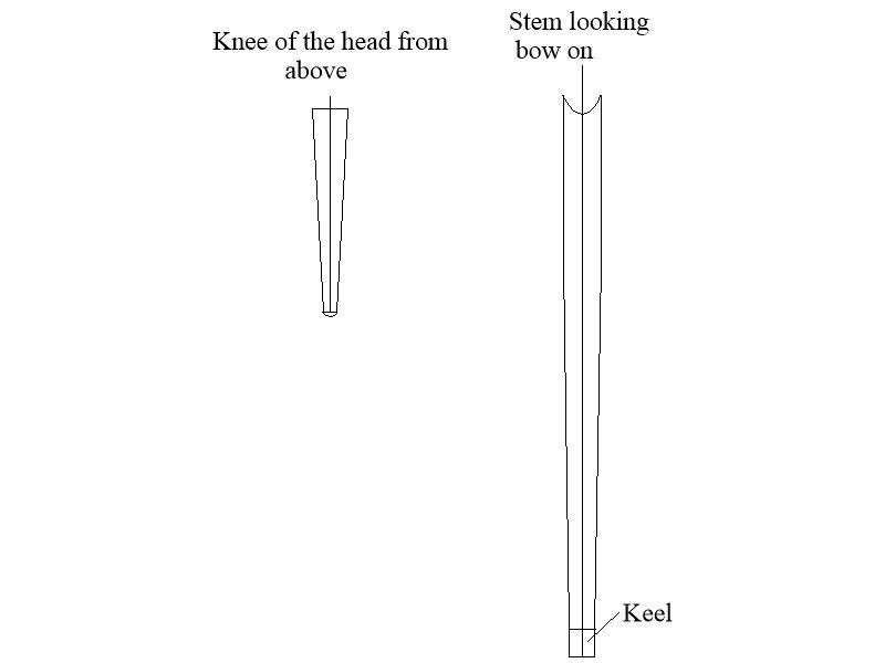
Hi Chris Sorry if my question raised more questions. It is probably easier to look at similar discussions here at MSW when this was raised on another build. I suspect your kit does not address this as only two kit makers I now of appear to give this any attention even though it is found on virtually every RN ship in the 17th to early 19th centuries. https://modelshipworld.com/topic/34577-taper-of-the-keel-stem-knee-of-the-head-and-stern-post/#comment-986943 and https://modelshipworld.com/topic/32748-hms-bellona-by-nearshore-corel-1100/page/2/#comment-982279 Post #40 Just as the stern post narrows in breadth from the upper portion down to match the keel, the stem also reduces in breadth so it matches the breadth of the keel where they meet at the boxing joint as the keel tapers in breadth for and aft from midships. Looking down on the knee of the head from above it also tapers from the stem down to about 6 inches at the area of the figure head on a 74. I do not have my books with me so not sure on a first rate, but I am guessing it would be similar. In the end, as with the majority of kit makers, most model builders are not aware of the tapering or are not overly concerned with it so it will likely never be noticed if not done. The downside is that the figure head, if a carved person will surely be bowlegged. 😀 Allan
-
Looking good Chris. Hard to tell from the photos if the knee of the head and stem have been tapered which would be a significant amount. Do the instructions indicate how much the stem is to be tapered vertically and knee of the head from the stem to the seat of the figure head? Allan
-
At your scale, the method of assembly of the ratlines themselves makes sense but how do you secure/wrap the shroud pairs around the mast? What is the spacing from ratline to ratline? Many thanks Allan
-
FWIW Bellona coppering. https://www.rmg.co.uk/collections/objects/rmgc-object-66299 Copper is over the rudder hardware.
- 78 replies
-
- 5
-

-
- Sphinx
- Vanguard Models
- (and 1 more)
-
Hopefully Ed Tosti (Naiad and Young America) sees this and can add some information. I had the privilege to visit him at his home quite a few years ago and see his collection of miniature military figures prior to his fabulous work on the ship models and books. I have never seen better representation than his collection. Maybe PM Ed to ask if he can lend some advice/methods based on his experience. Allan
-
Hi Eric If the hull is going to be painted over or otherwise covered, it does not really matter. But if the planking is going to be uncovered look at the planking tutorials in the article database here at MSW and you will see instructions on starting with lining off the hull and then planking starting with the wales then working down to the garboard and up to the highest strakes. https://thenrg.org/resources/Documents/articles/APrimerOnPlanking.pdf There are differences in some kits' planking, including OcCre where they have planks that are not properly tapered so some of them do not end at the rabbet as they would in real practice (with the exception of a drop strake or stealer if needed.) If you have not already seen them, these four videos are well worth watching as they give an alternative to spiling that works well Part 1 --- https://www.youtube.com/watch?v=KCWooJ1o3cM Allan
-
When you print the barrels from the 3D drawing you posted they will look MUCH better than the barrel in the second photo. Congrats on going the extra mile, even at this small scale. Allan
-
The inboard profile confirms these are gratings and a ladder way as there is nothing above the deck indicating a skylight which could be instead of, or in addition to, gratings and ladderway. Pegasus was launched in 1776 and fitted out in January 1777 and the RGM plans were drawn between late 1776 and early 1777 so might be as-built plans. If you look at the Pegasus drawings from 1775 (https://www.rmg.co.uk/collections/objects/rmgc-object-84572) there are differences between this design drawing and the drawing made at about the time of her launch. (https://www.rmg.co.uk/collections/objects/rmgc-object-84573) Greg makes a good point that the clerestory-style companionway may be appropriate, but I just wondered why the kit plans do not match the originals as there is nothing to indicate there was such a companion way. In TFFM David does state that the inclusion of a companion top is a thorny subject, He goes on to say ships-of-the-line had clerestory style lights from about 1750 that could be removed and replaced by gratings. And, as Greg points out TFFM makes note there was a reference from 1779 that allowed sloops of 300 tons to have one companion. As Pegasus sunk two years before that, I am not totally convinced she ever had one, but as with so many things in our hobby, who knows? No matter, I agree with Greg that they add character to the deck layout and you should go with what makes you happy. Allan
-
Hi Richard This is really interesting. Neither of the QD or inboard profile contemporary plans of Pegasus 1776 show a skylight, just gratings and ladderways. Perhaps the skylight was added later but she sunk 10 months after being launched. I thought maybe the draftsman just left it off the drawing but, while it is a larger ship of which there was a Pegasus (28) 1779 in the group it is very clearly shown on the Enterprize (28) 1774 drawings (second set below). I would think that if there was supposed to be a skylight when launched, it would be on the original plans. If you just leave it off the model, it can be argued, based on contemporary evidence, it never existed. Allan https://www.rmg.co.uk/collections/objects/rmgc-object-84573 https://www.rmg.co.uk/collections/objects/rmgc-object-84575 https://www.rmg.co.uk/collections/objects/rmgc-object-83179 also available in high resolution on the Wiki Commons site https://www.rmg.co.uk/collections/objects/rmgc-object-83181 also available in high resolution on the Wiki Commons site
-
If the piece is already glued on the model I tape a soaking wet paper towel to the part and rehydrate it every few hours. Takes overnight and then some at times. Another example, but purposely gluing parts together that will need to be separated....... when I have to make very small strips of wood such as window frame pieces that are about 0.025" square at 1:64 I thickness sand a board to that thickness then cut strips with a rule and scalpel. These are never exactly at the same thickness as the original board, but too small to take through the thickness sander one at a time. I glue 5 or 6 pieces side by side with the hand cut edge being the wider face of the glued up strip. I then can run through the sander without worries. Once done I soak the assembly for an hour or so and the glue melts and the pieces come apart very easily. Takes a little scraping of the glue afterwards but otherwise a relatively easy task. Thicker pieces take longer but can be done. The hard part for me is having patience. Allan
-
Sorry Ron, wish I could have been of more help. Allan
- 626 replies
-
- 2
-
-
- Indefatigable
- Vanguard Models
- (and 1 more)
-
David Antscherl goes into great detail on how to make realistic binding, middle link, toe link and preventer plate in The Fully Framed Model Volume II pages 262-265. Way to much to post here, but as he is a member, hopefully he will see this and post some information from his book. Allan
- 626 replies
-
- 1
-
-
- Indefatigable
- Vanguard Models
- (and 1 more)
-
Clamps are great tools when needed, but that should not be very often IF the parts are pre-fitted before gluing them together. This includes planks if they have been tapered and pre-shaped properly. A tapered and spiled (or pre-bent) plank will hold after about 30 seconds of finger pressure with PVA, same as with CA and will not lift from edge bending. If it lifts and/or does not hold and springs loose it is not yet properly shaped and needs to be re-worked or replaced. Allan
-
As will water. Allan
-
Welcome aboard the good ship MSW Kai! Allan
-
Hi Chris Happy retirement to you!!! It can be an adjustment, and not only for the retiree😁 Not to stir up a hornet's nest (yabuhebi?) but maybe consider studying the four part video on planking done by MSW's own Chuck Passaro. It will make things much easier for you in the future as well as yield realistic planking. Part One can be found at https://www.youtube.com/watch?v=KCWooJ1o3cM This will help you eliminate all the lifting you are getting from cold edge bending. Is there a reason your log is in the 1801-1850 section rather than the 1750-1800? Many folks enjoy following the various Victory builds so might be missing yours as it was launched in 1765. Allan
-
Well said B.E. I did a 1:64 drawing to see if they show up and they are quite clear when printed. I am guessing that it would not be difficult to include a sketch or verbal instruction about these hoops even if supplying material is impractical. Allan
-
Hi Chris I looked at a number of contemporary drawings of masts and as you say, the wooden hoops on either side of the wooldings are not shown on any that I have seen. Looking at photos of contemporary models they all have the wooden hoops above and below the wooldings but these are all 1:48 scale so a good bit more noticeable than they would be at 1:64. Allan
-
Hi Glenn, Sorry if this was raised before. There are no wooden hoops shown above and below the rope wooldings on the masts which I thought was always done so they did not get chafed or move on the mast. Was it not as common as I thought or could this have been an anomaly on Indefatigable? Regardless, she continues to be a superb build. Allan
-
There have been several threads on this here at MSW, but I do not recall ever seeing any information based on contemporary sources regarding the finish appearance which could be interesting. Glossy finishes on modern fiberglass and steel hull yachts is common, but for warships I was taught that a matte finish is more realistic. This may not be correct, but wouldn't it make sense that the last thing a warship needs is a glossy finish so it stands out? I am pretty sure high gloss finishes were not done, but in the end, go with what makes you happy. Allan
-
......if you are referring to the main stay and main preventer stay. If you are referring to the forestay and fore preventer stay, the collar was put on double from about 1733, not single like in the photos above. In addition, after 1773, the collar closest to the sprit was an open heart, not a closed heart. The drawing below for the forestay and fore preventer stay collars is from page 41 in James Lees' The Masting and Rigging of English Ships of War. Putting a double collar may not be practical or easy at 1:100 scale. Allan