


TJM
-
Posts
260 -
Joined
-
Last visited
Content Type
Profiles
Forums
Gallery
Events
Posts posted by TJM
-
-
7 hours ago, Beckmann said:
Will you dress Ltn. Hornblower in a danish uniform?
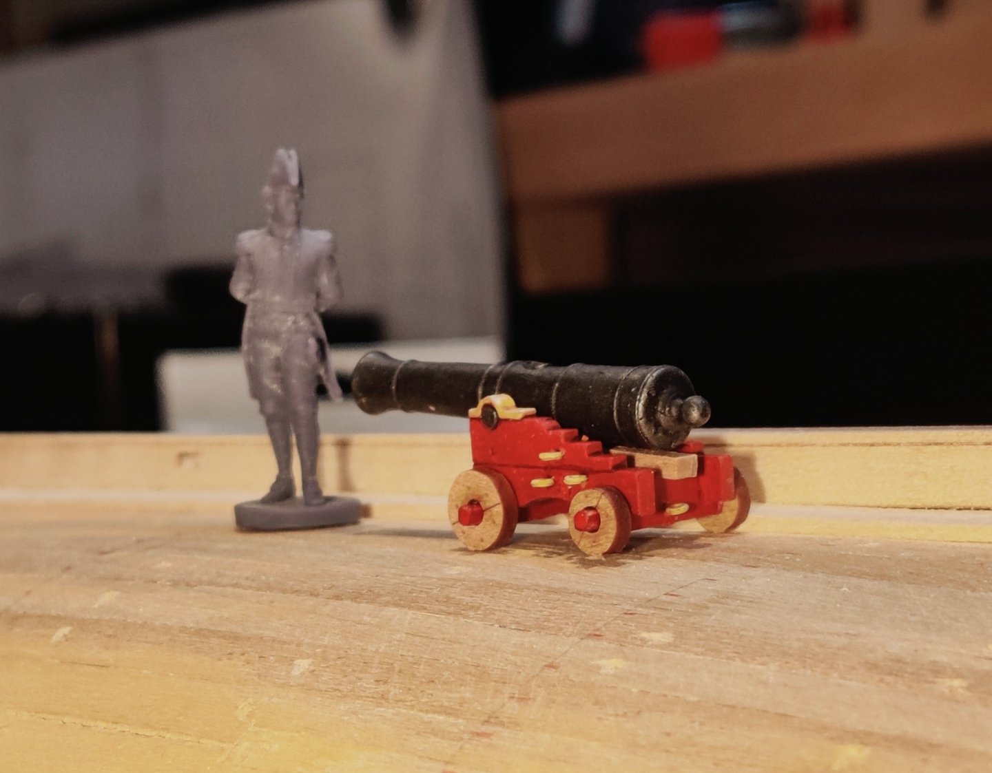
Yes indeed! He will look something like this:
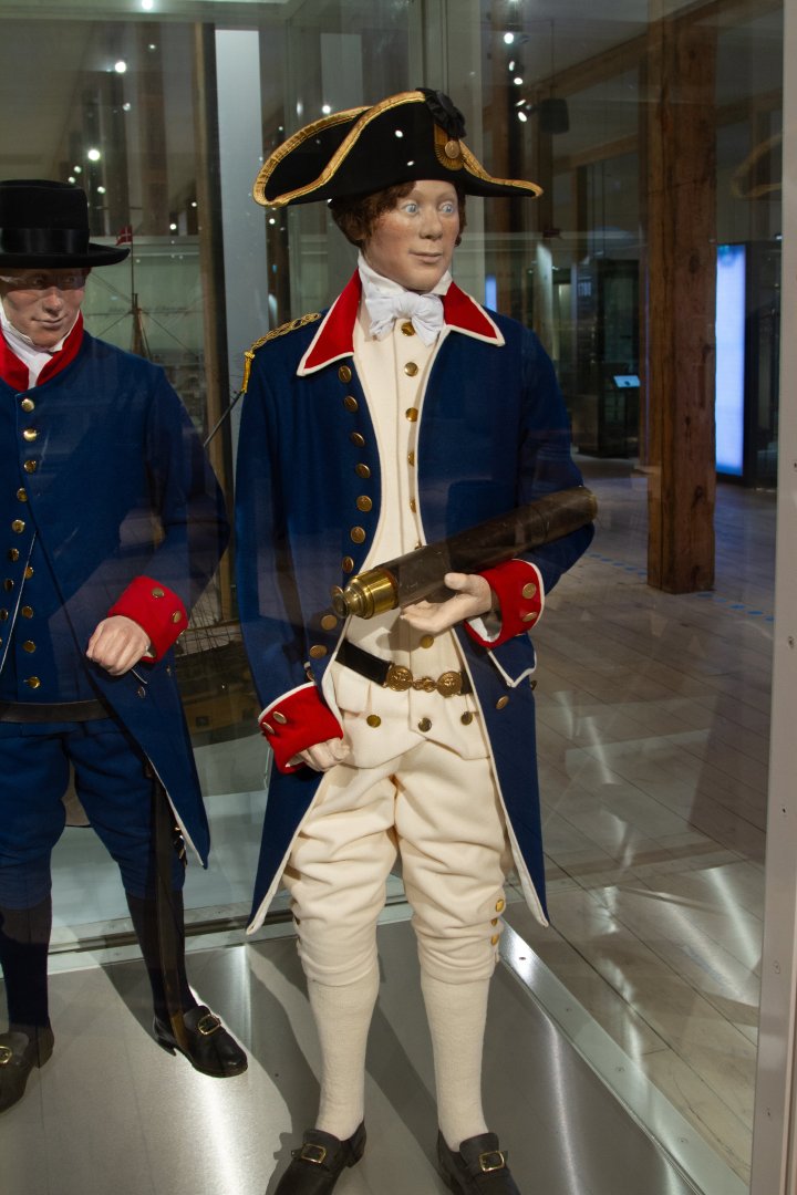
For now, I just call him Løjtnant Hornblæser - I think you can guess what that translates to 😉.
- DonSangria, cotrecerf, Thukydides and 1 other
-
 4
4
-
Log entry 21 - cannon, colours and inorganic chemistry!
Hi Everyone,
Planking is progressing, albeit quite slowly. I will show that progress after a few more have been added.
To break up the quite long and repetitive task of the planking, I have started to look into the cannon - also a long task that I prefer to do a little at a time and not having it as a huge chunk of work when I reach that part!
During my research, I have found that Danish cannon carriages were painted in basically the same way for a very long time, and it is a bit different from the British schemes of that time.
From at least the 1610's to 1830's, the carriages themselves were red, painted with what is still in Denmark called 'svensk rød' - Swedish red. That is iron oxide - I guess that is likely the same colour as the Royal Navy used?
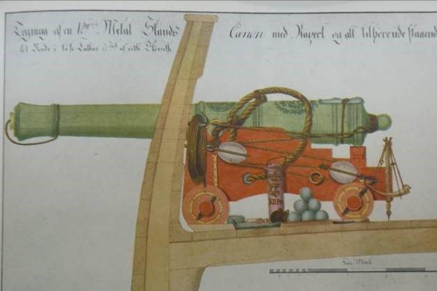
However, all wrought iron parts were painted with lead oxide pigmented paint for corrosion protection. Here are a few reference images:
A manuscript illustration - it seems to be earlier than Christianus, as it clearly depicts a bronze cannon, but the yellow wrought iron is clearly evident.
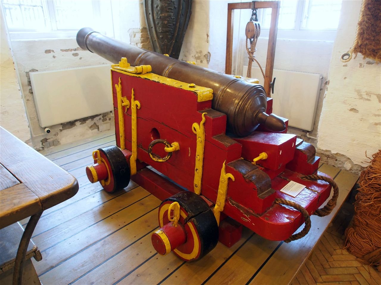
An original cannon at the now defunct Orlogsmuesseet. The carriage is probably not original and it has definitely been painted recently, but is shows how the historians believe it would have looked.
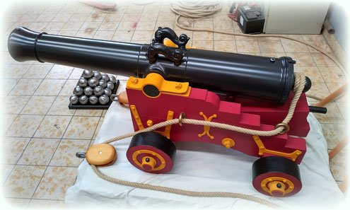
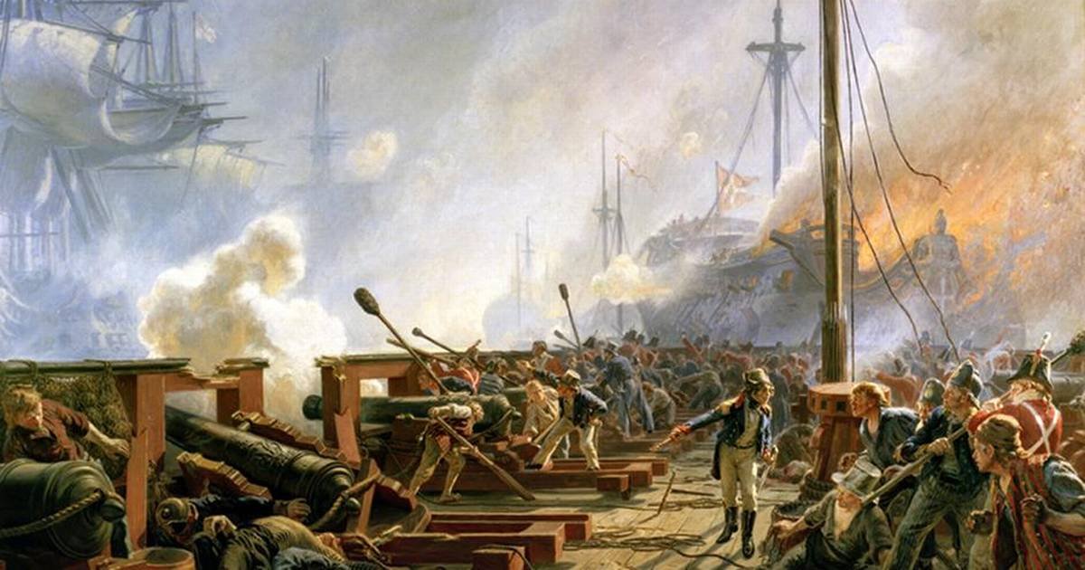
A commercial replica og a small Danish cannon.
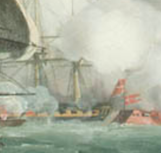
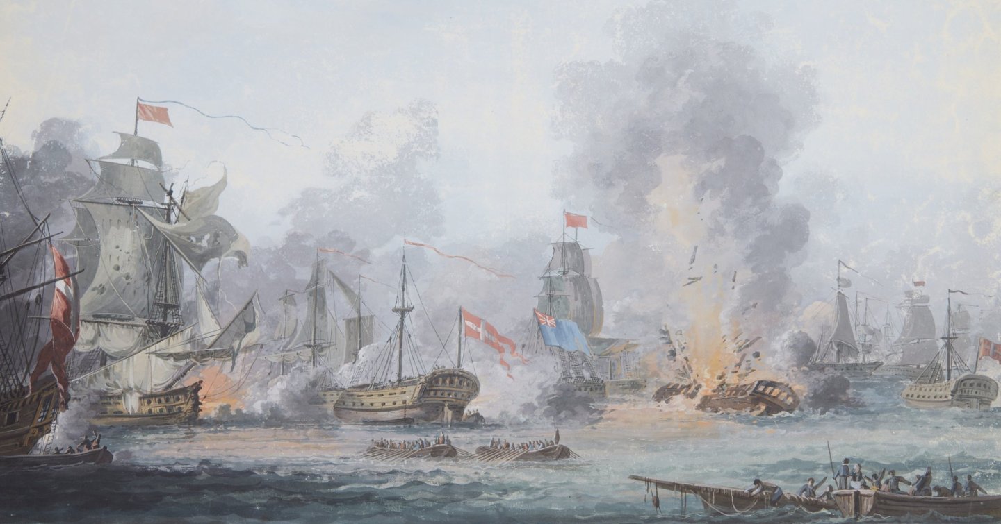
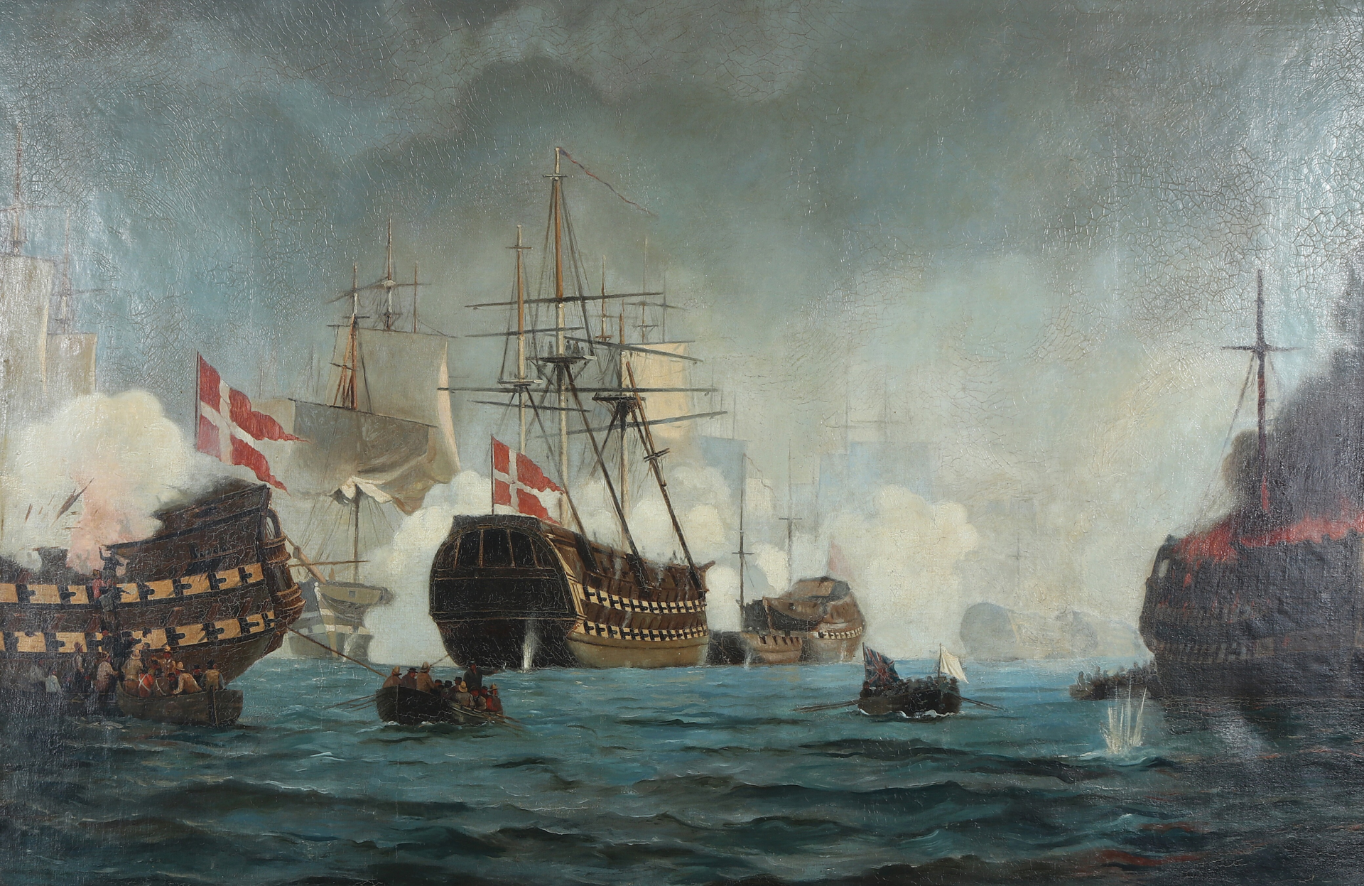
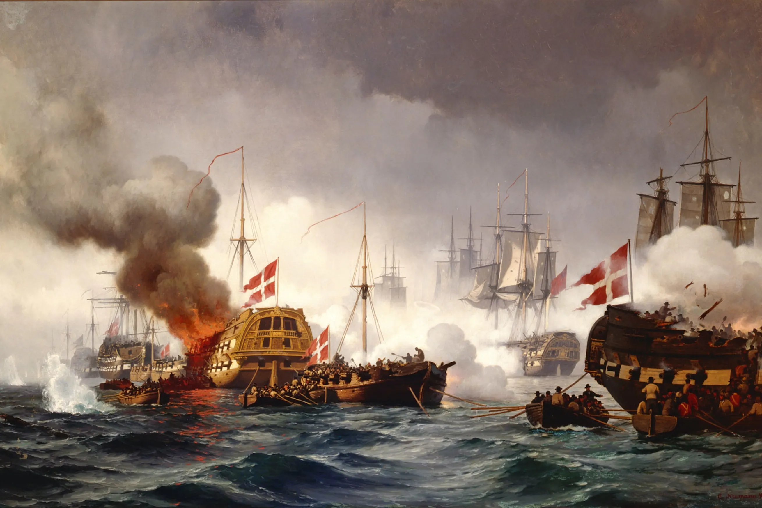
An image depicting 'Slaget på Reden' - the First battle of Copenhagen. The toppled cannon in the lower left shows the yellow wrought iron.
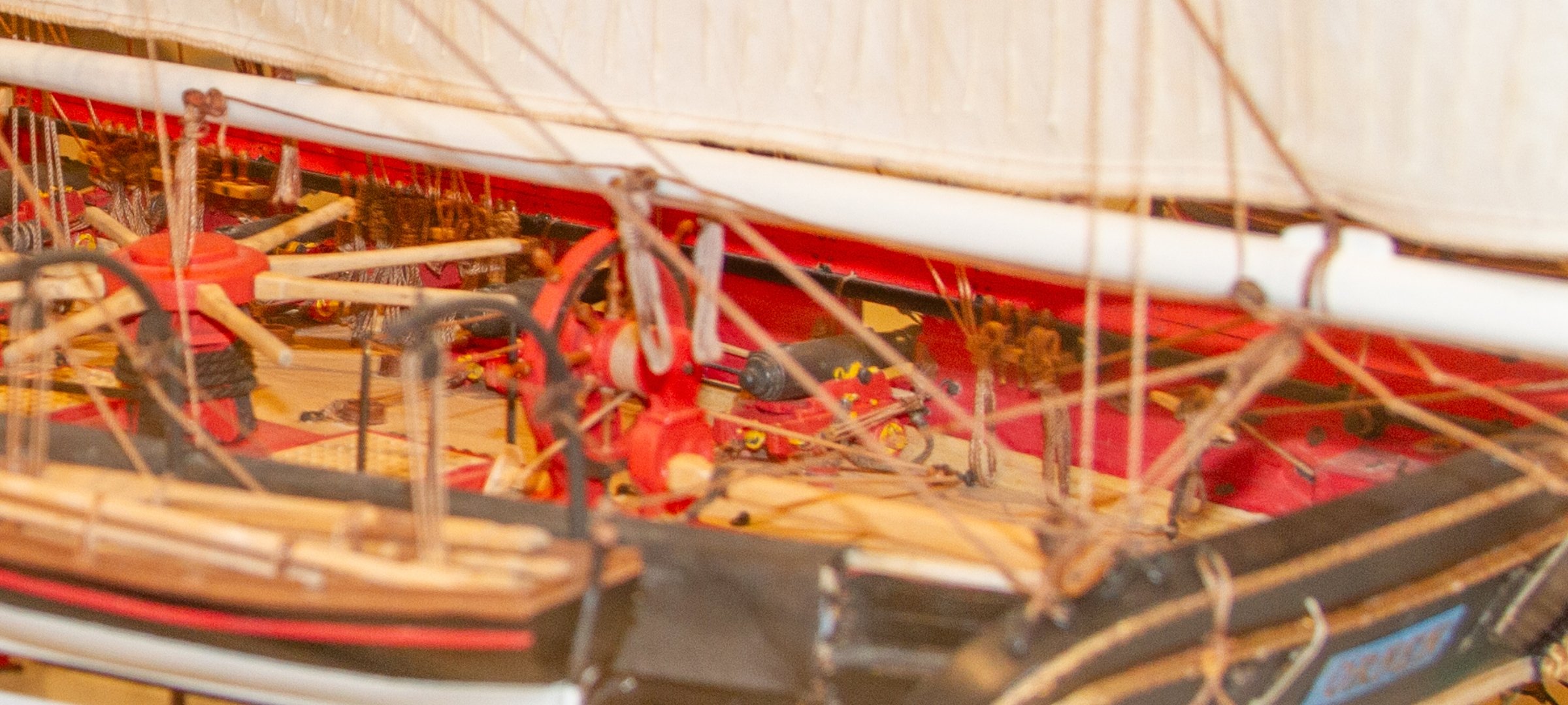
Apart from these, there are many morder models at the War Museum in Copenhagen showing this paint sheme:
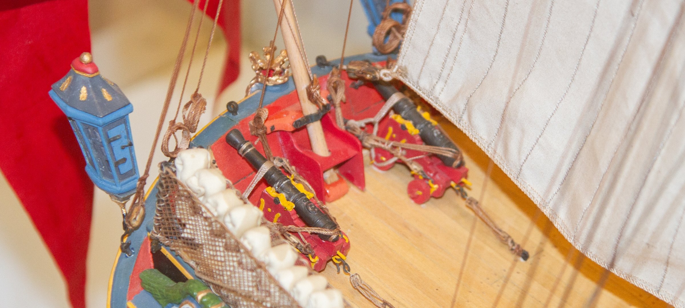
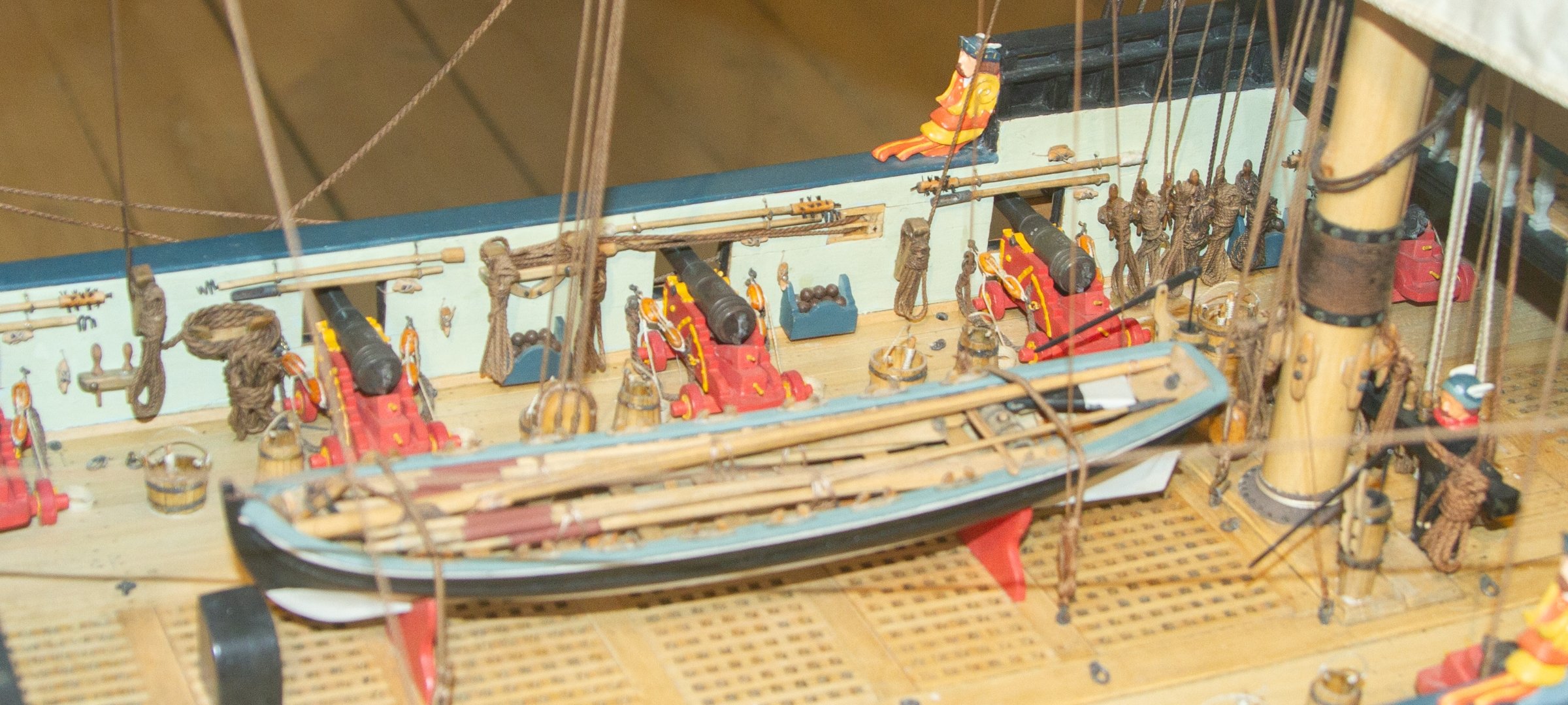
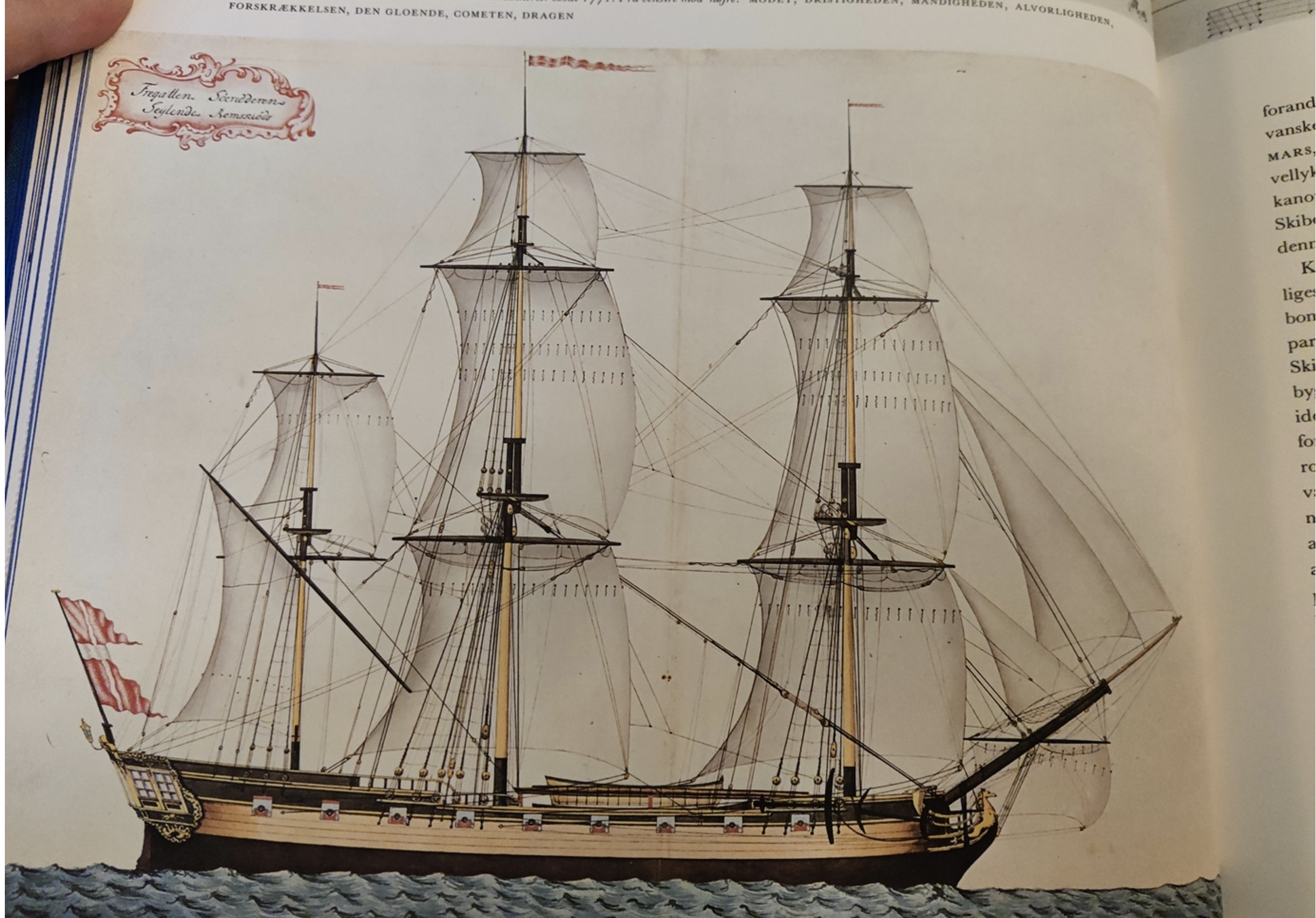
The frigate Bornholm (1770's):

The Gyldenløve (1670's):

The brig Ørnen (1830's)

These references all show a bright, yellow colour for the wrought iron parts, but in several sources the pigment is referred to as 'mønje', in English 'minium'.
This is where the chemistry comes in: lead oxide appears in many forms with minium being just one of these.
In the image below, you can see the comon forms. Black: lead(IV)oxide, PbO2. Yellow: lead(II)oxide, PbO. Orange: lead(II/IV)oxide, PbO•PbO2

The mixed, orange oxide is minium, but it looks way too orange compared to the reference material, even if the word minium is used to describe it.
Now, lead(II)oxide (yellow) had two mineral forms called 'litharge' and 'massicot'. Litharge is more orange and massicot is very bright yellow.
It is therefore difficult to know exactly what was used, but I will hazard a guess that it may have been a variable mixture of the different minerals minium, litharge and massicot, as chemically pure minerals were rare back then. The colour could therefore range from bright orange to light yellow.
I find this kind of thing fascinating. In the end, I decided to go for a warm, but relatively light yellow, as that seems most consistent with the reference material, though for good reasons, none of those are entirely reliable. This will be used for all wrought iron parts.
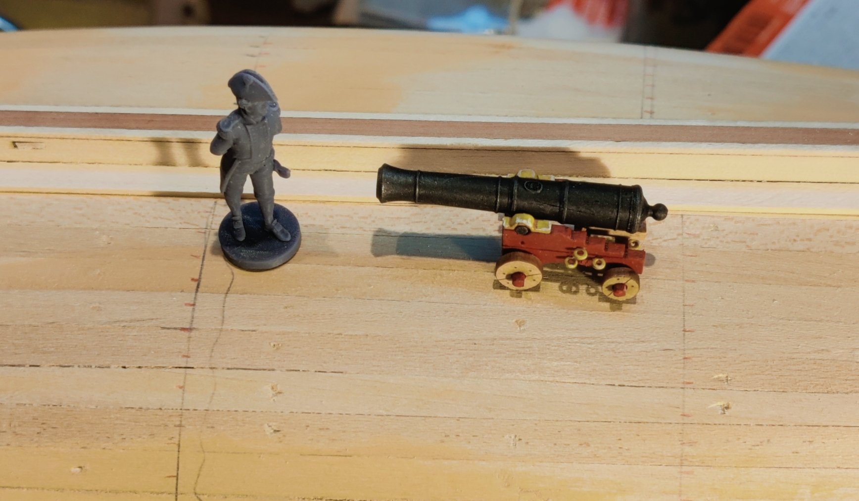
Here is what a canon will look like:

It would have been period accurate to also paint the wheels red, but that looks too toy-like for my taste, so I will keep them natural.
On a related note, I have come to the conclusion, based on all the image and model material I have found, that the inner bulwark would definitely also have been red on the Christiania. I will therefore mask off the exterior (non-cabin) part of the internal bulwark and paint that red as well. Luckily, it is not too late for that, I just need to be careful with the deck!
BR
TJM
-
I am looking forward to following this for sure!
- Canute, Blue Ensign, Ryland Craze and 1 other
-
4
-
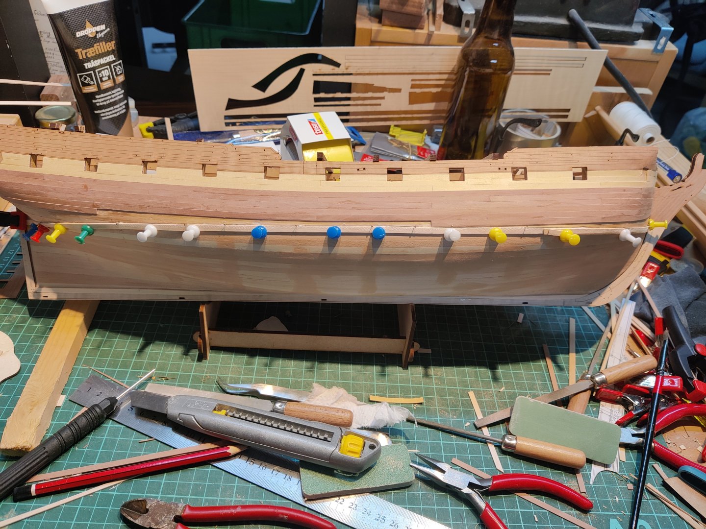
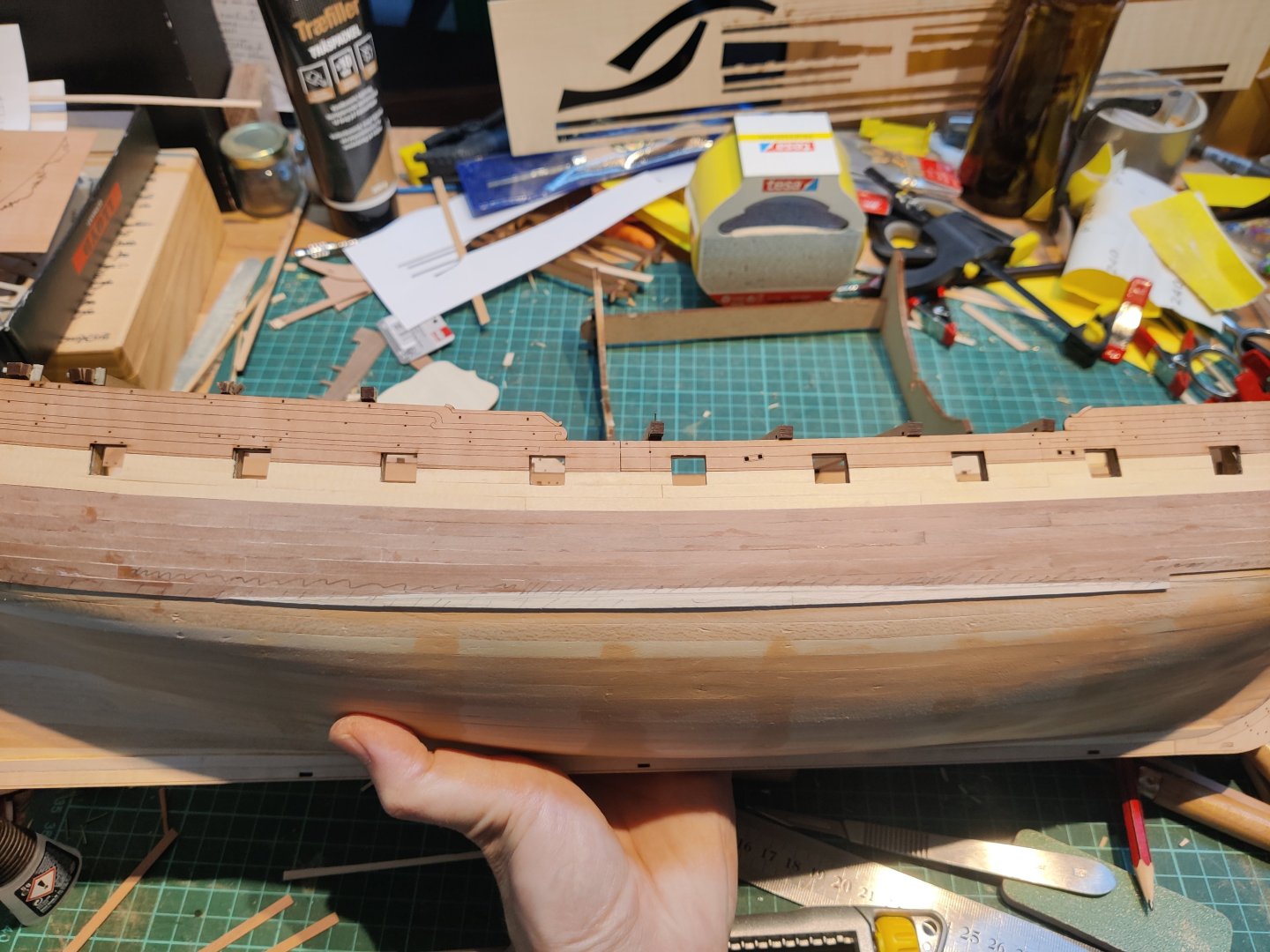
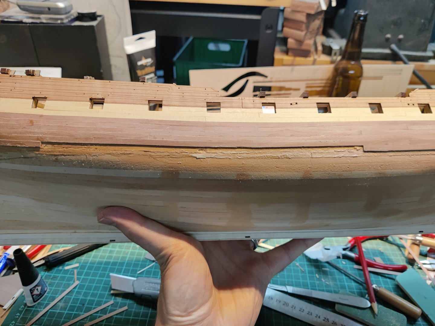
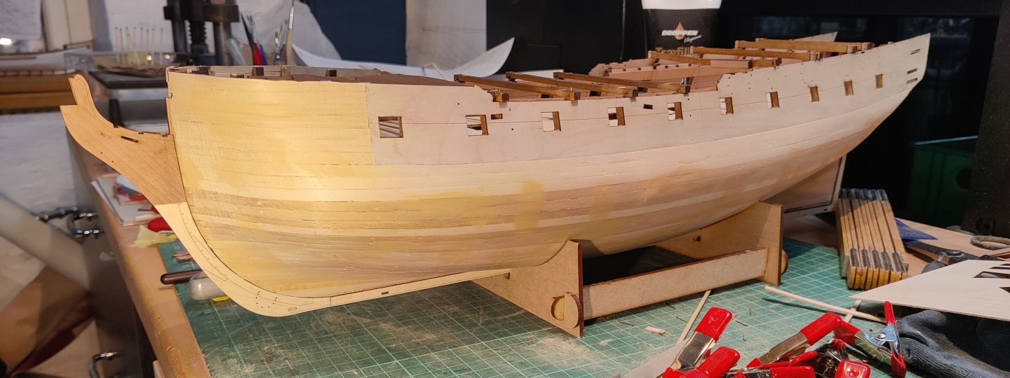
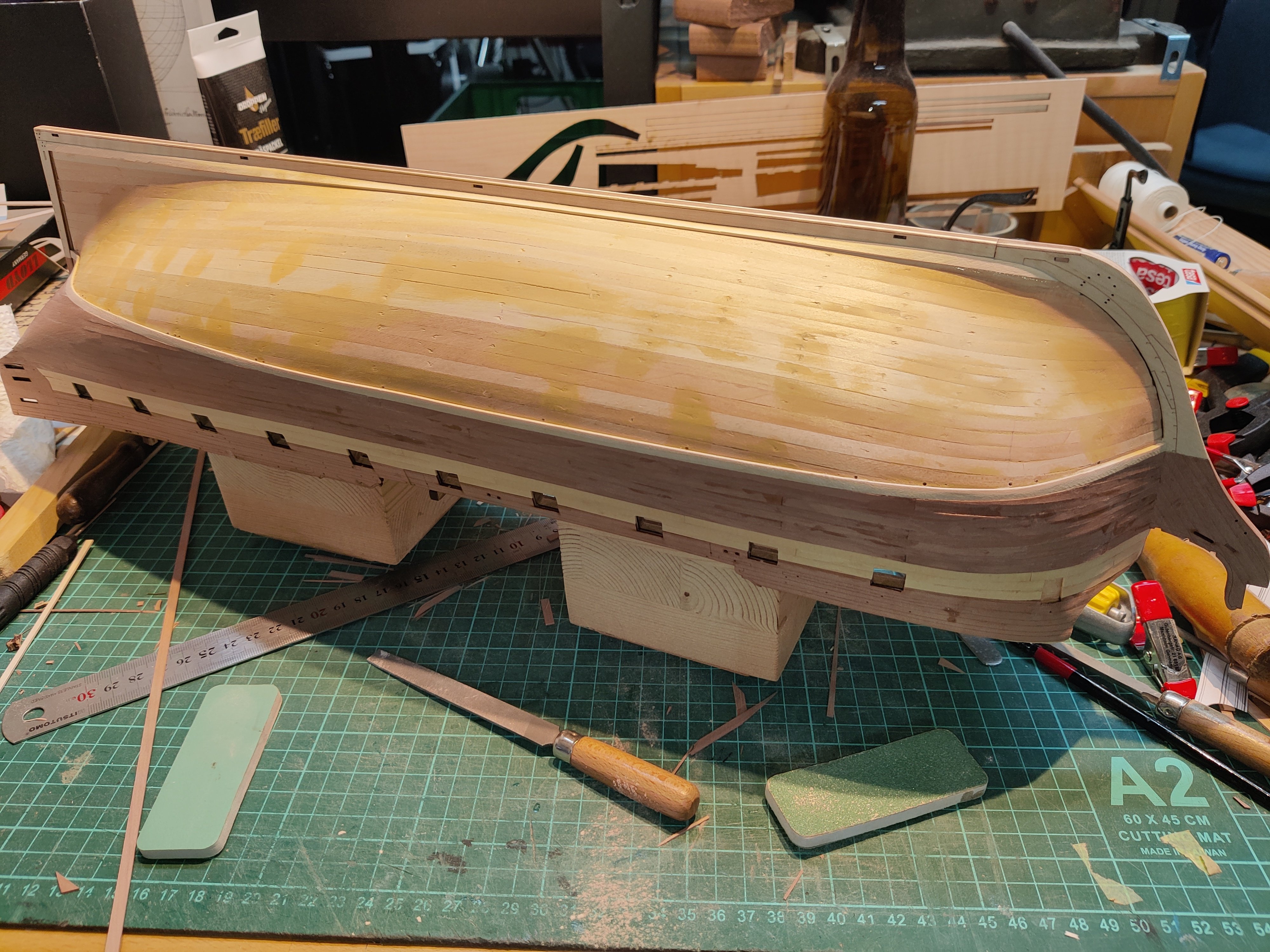
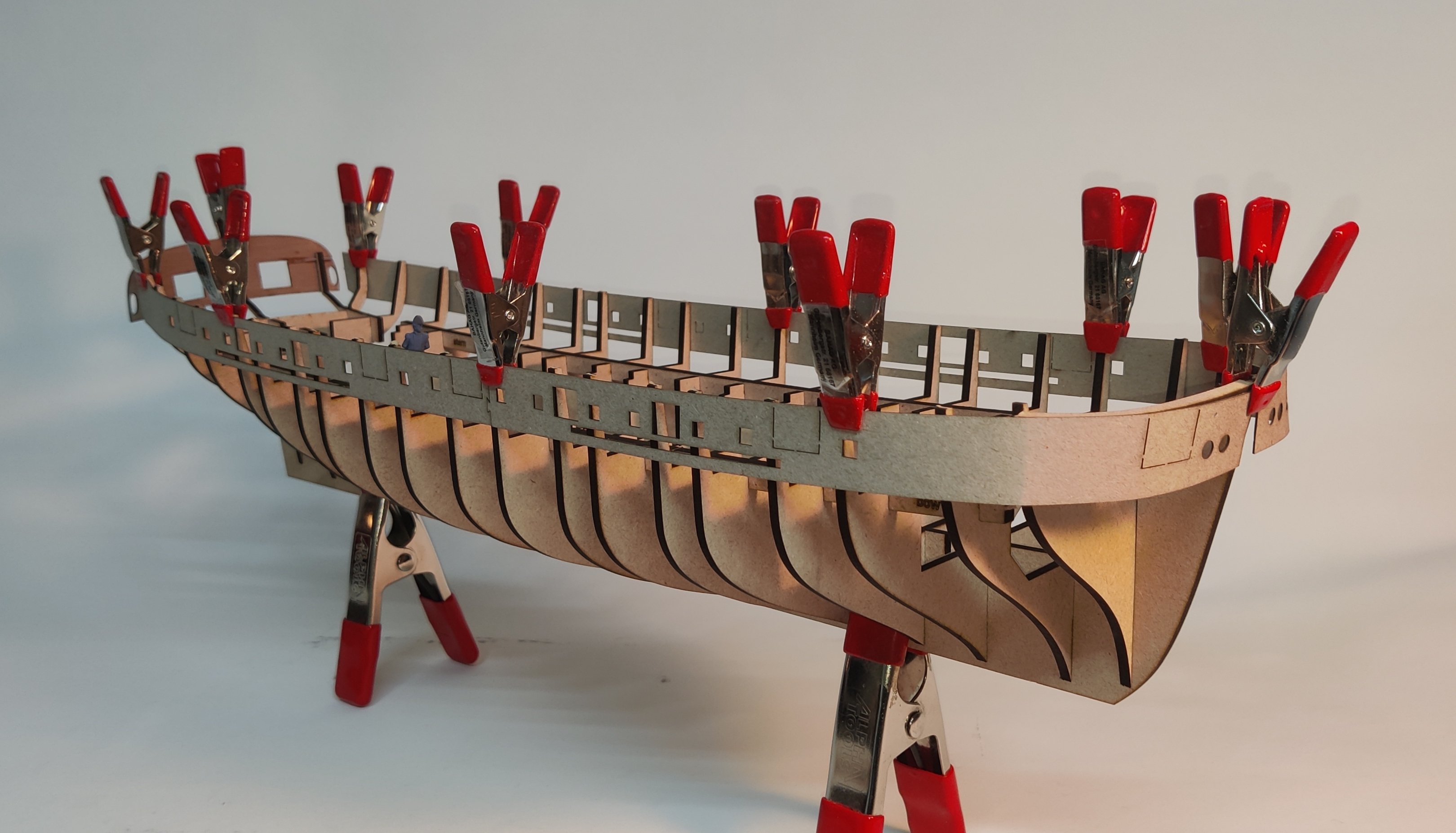
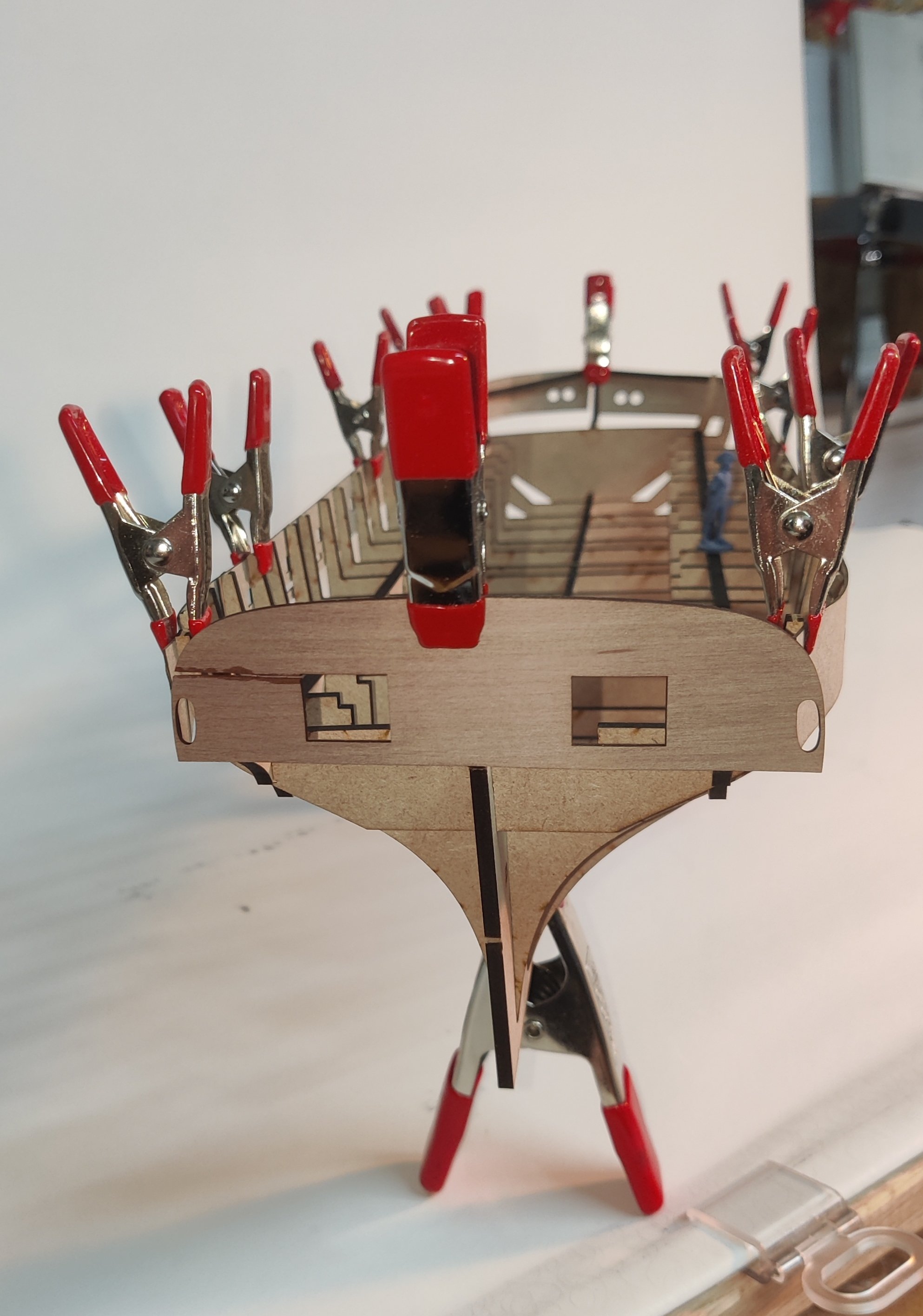
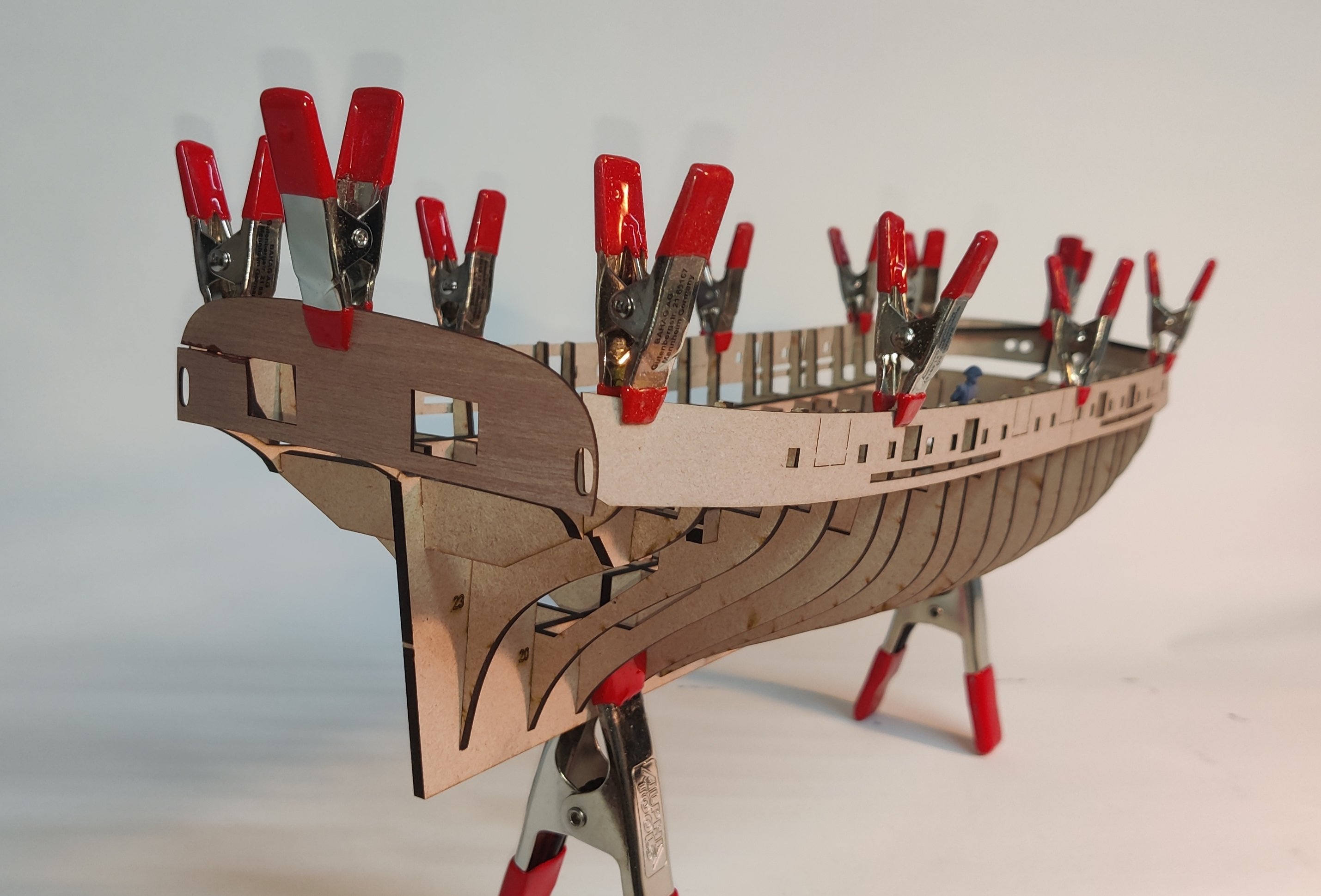
Log entry 20 - planking
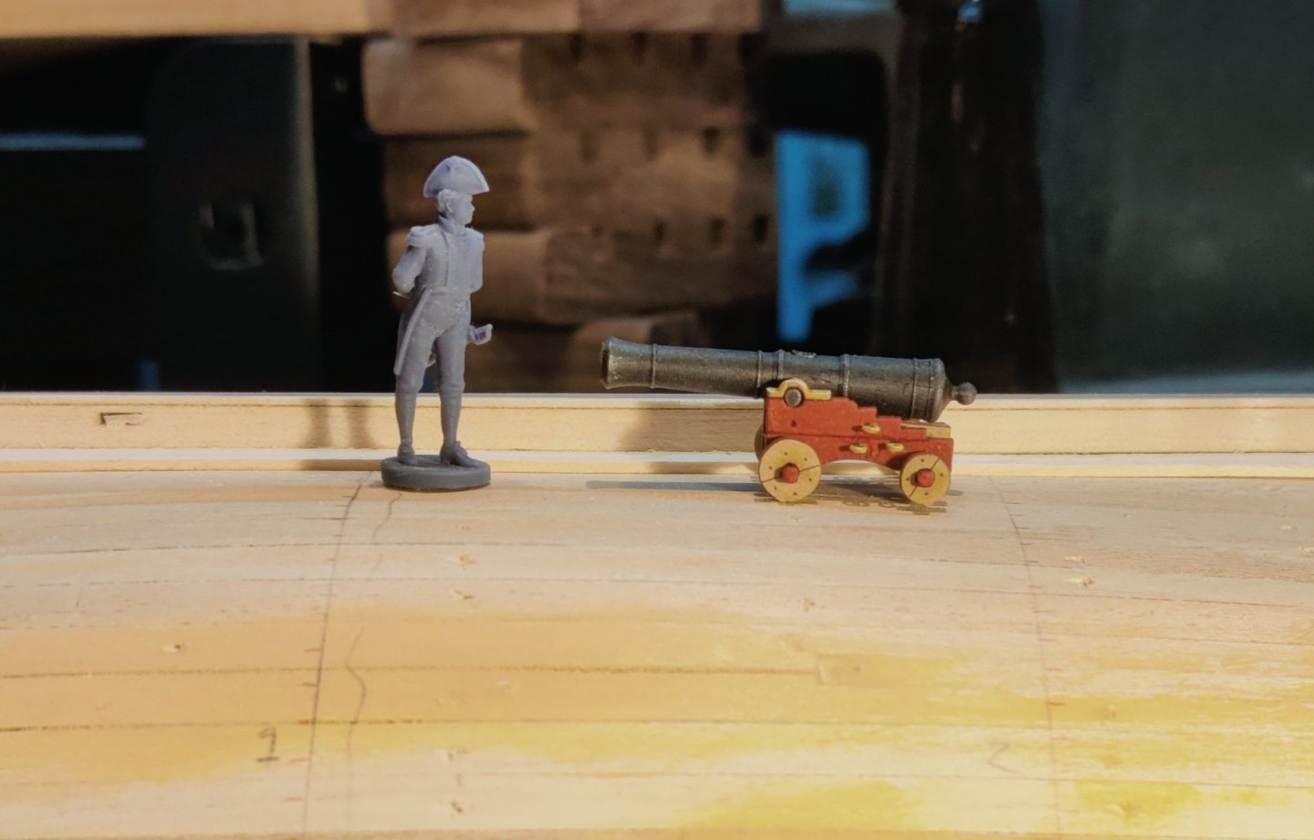
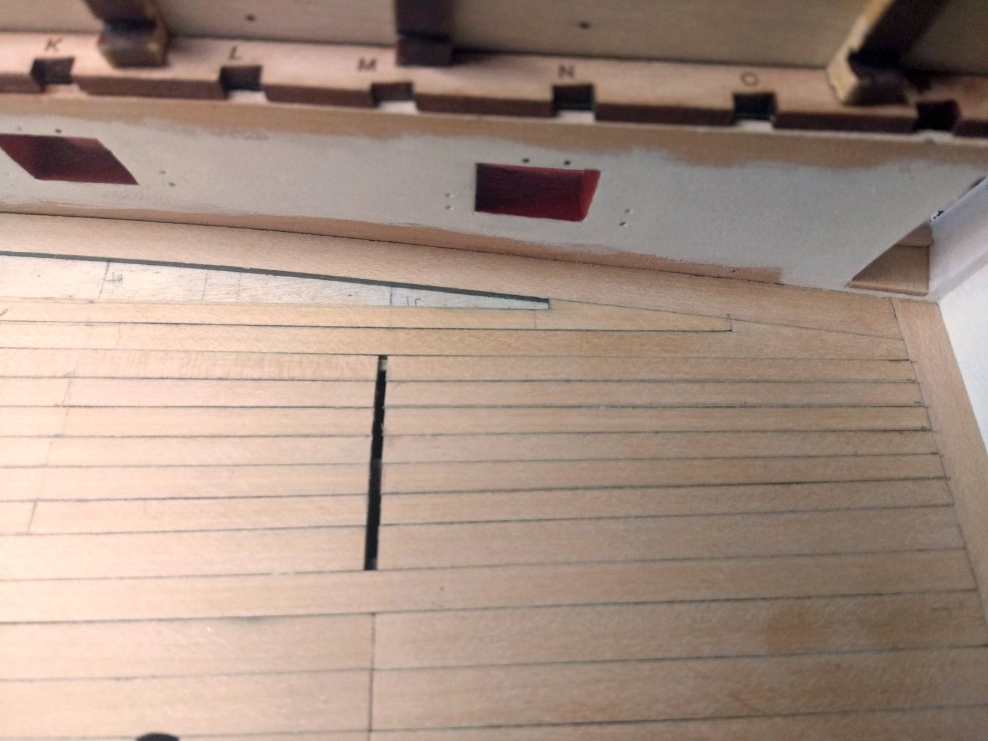
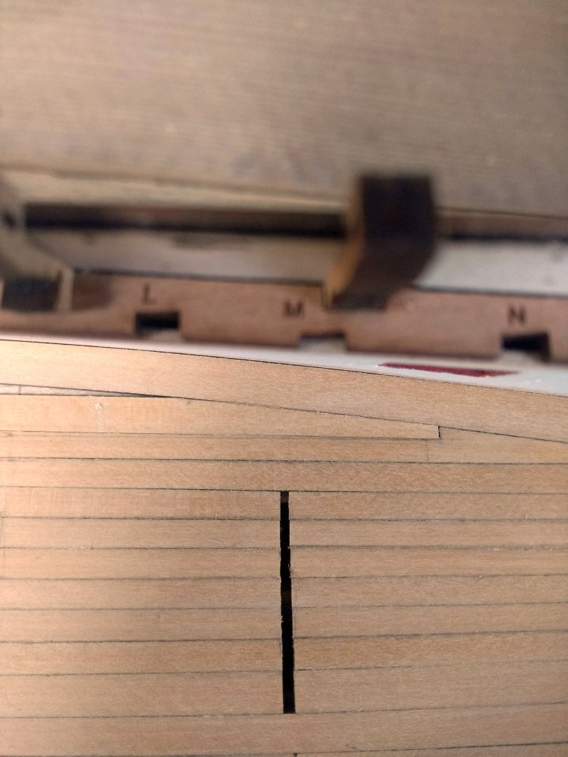
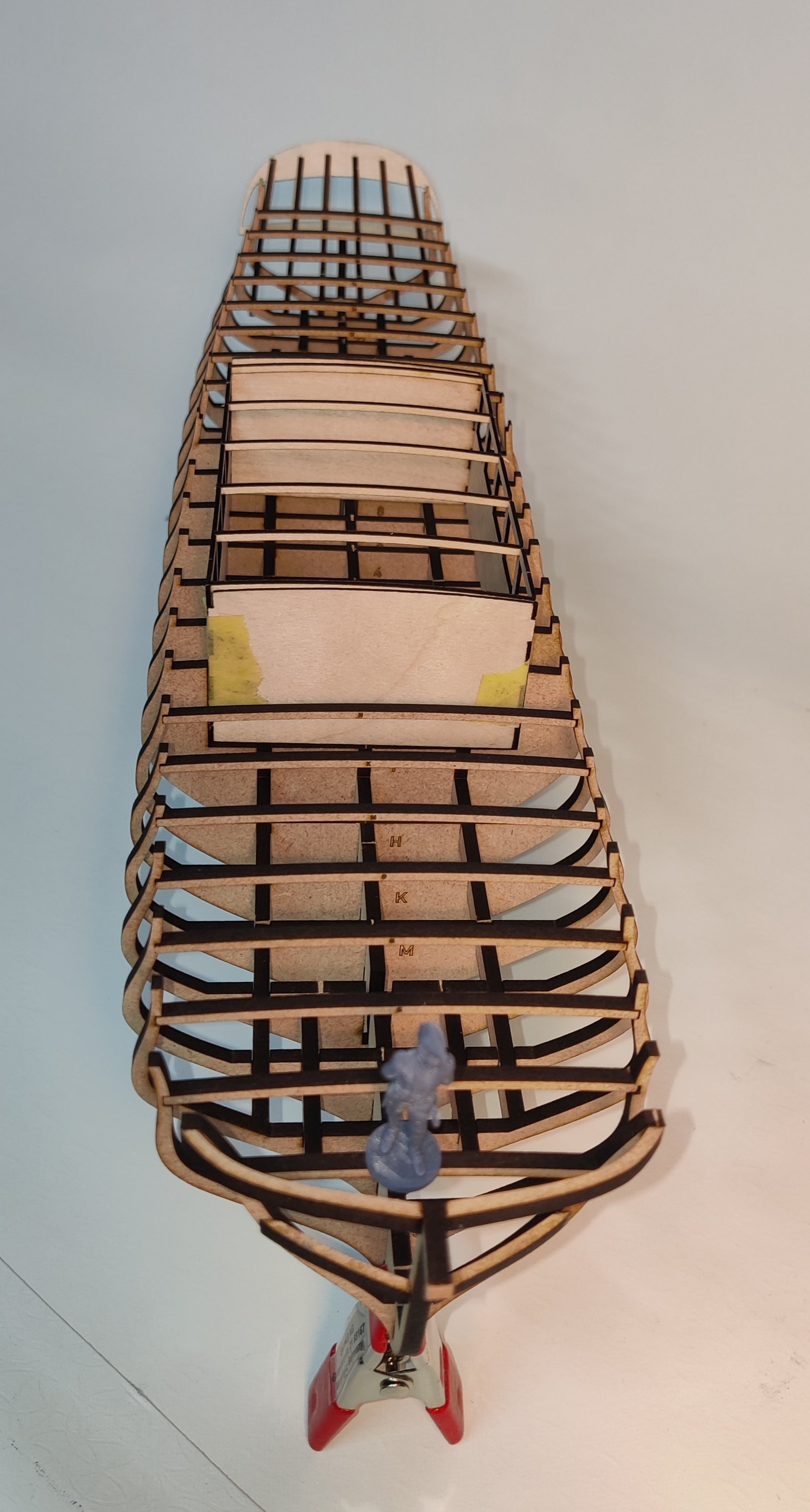
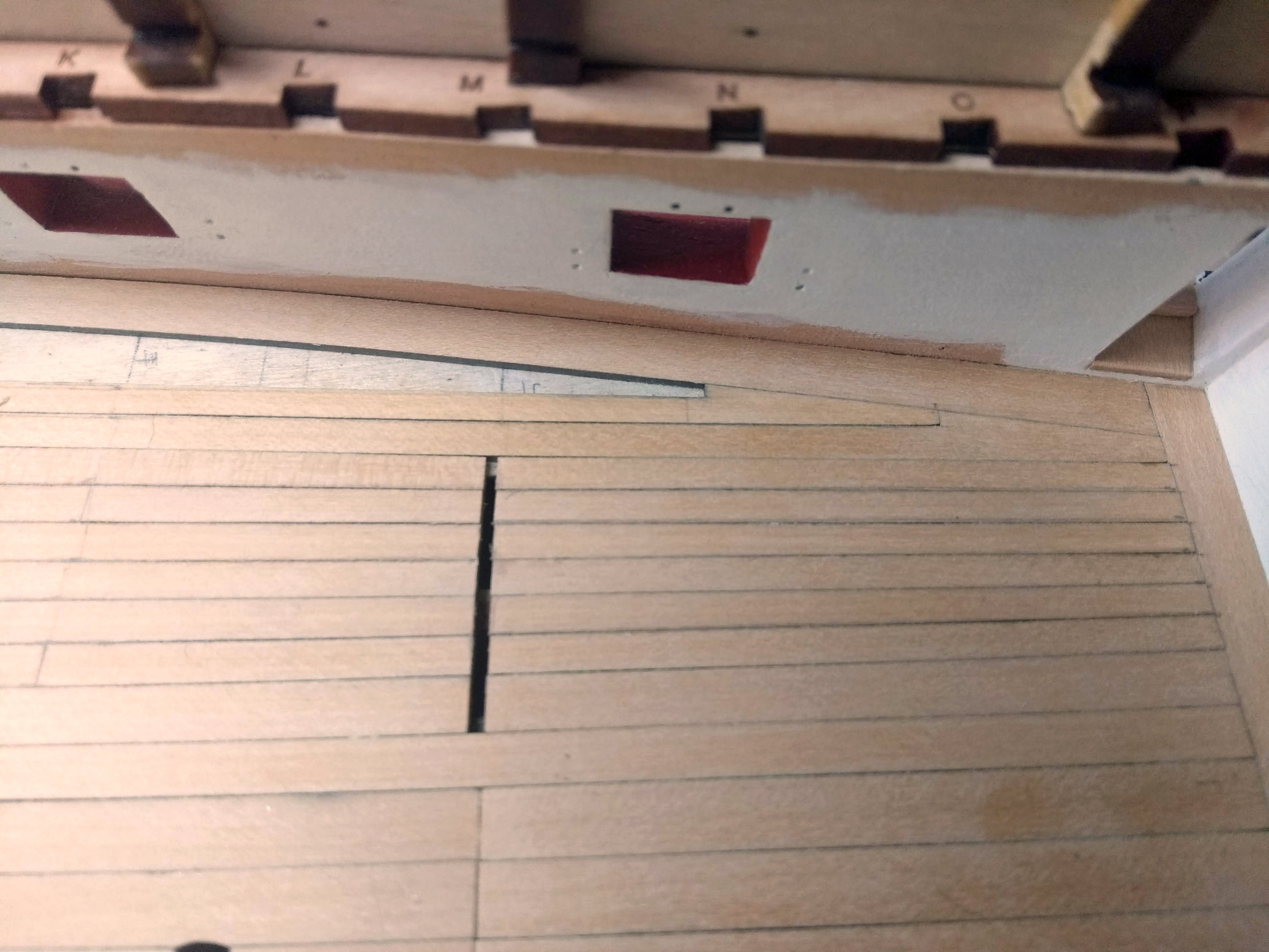
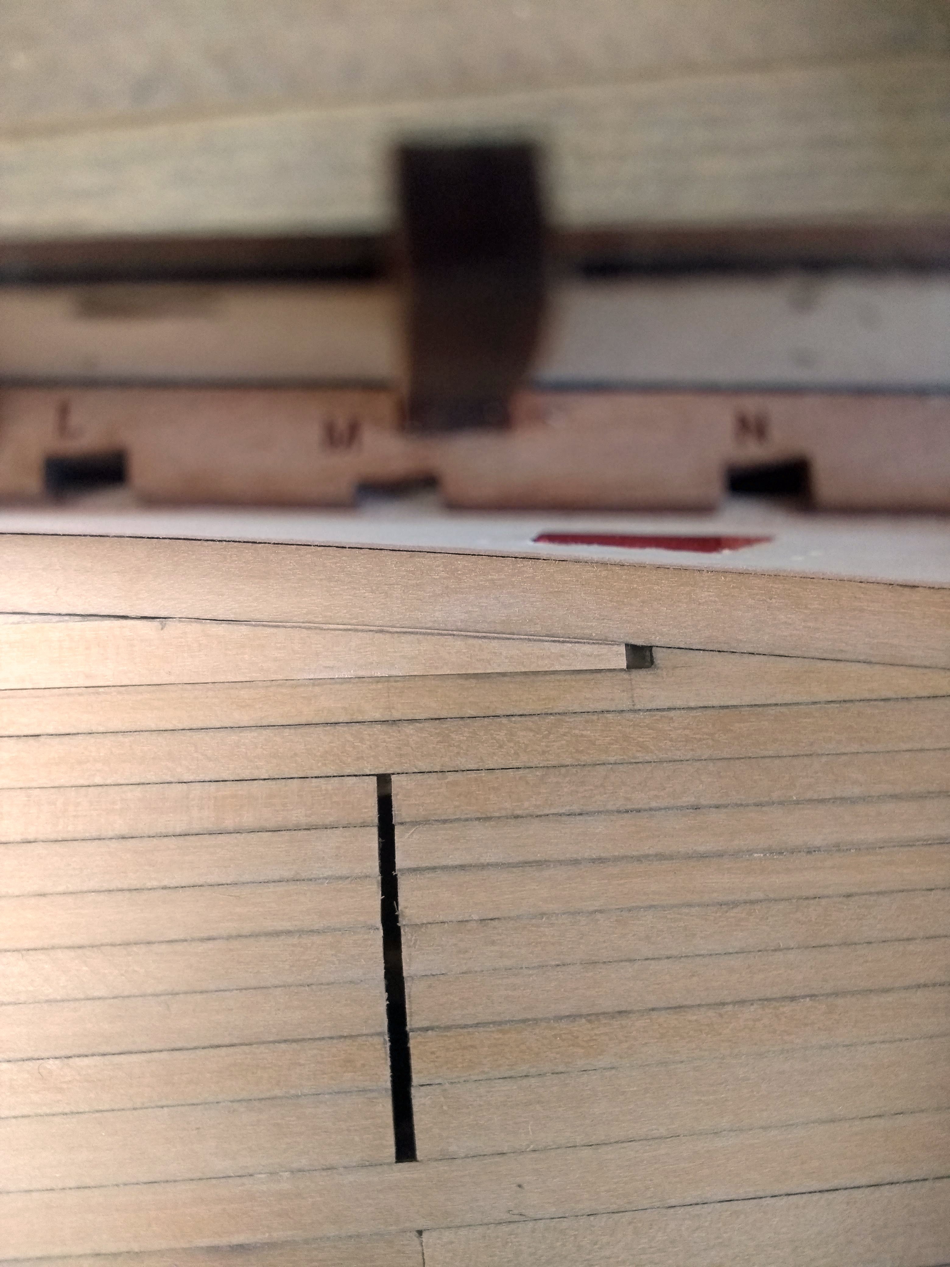
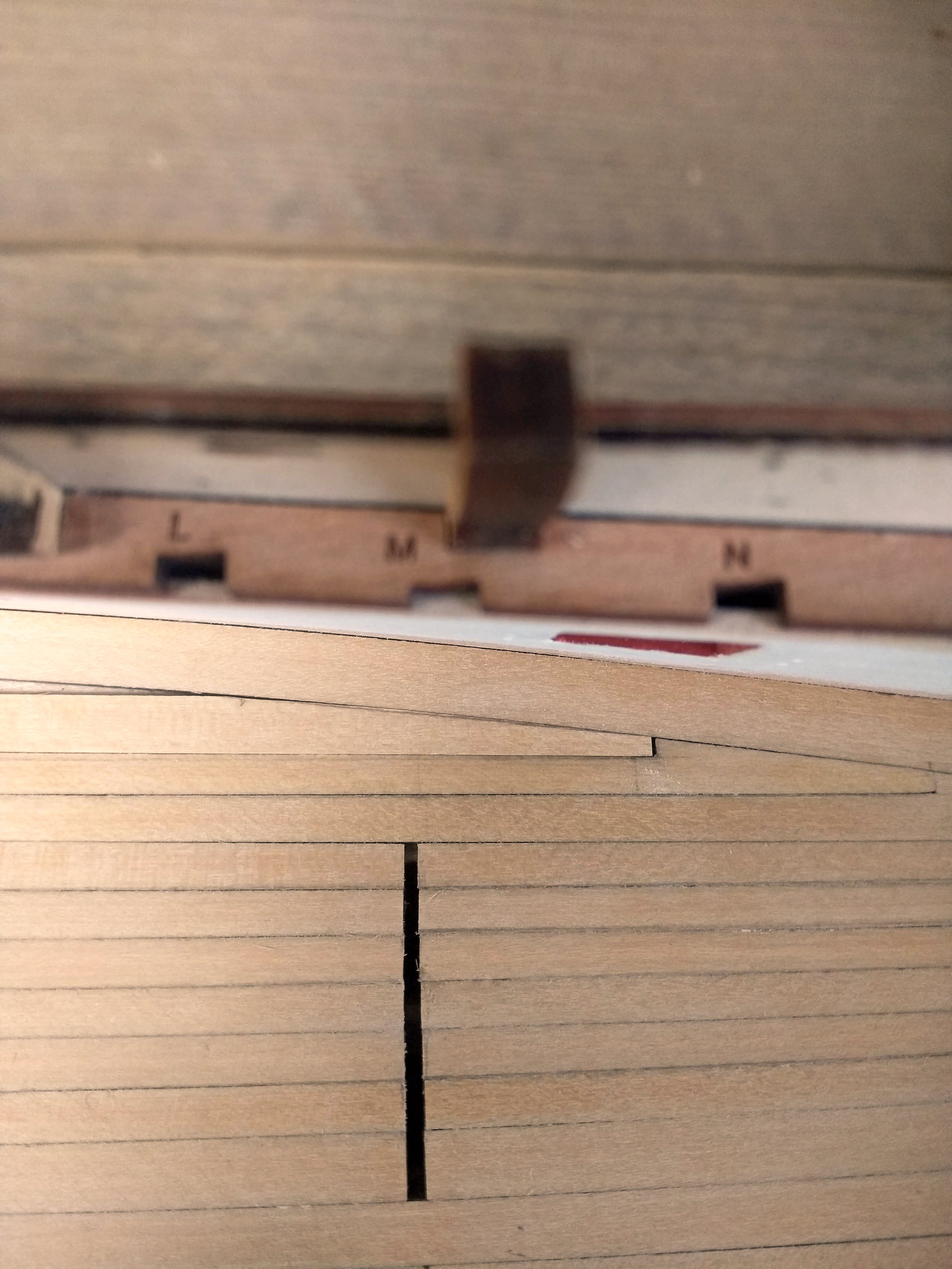
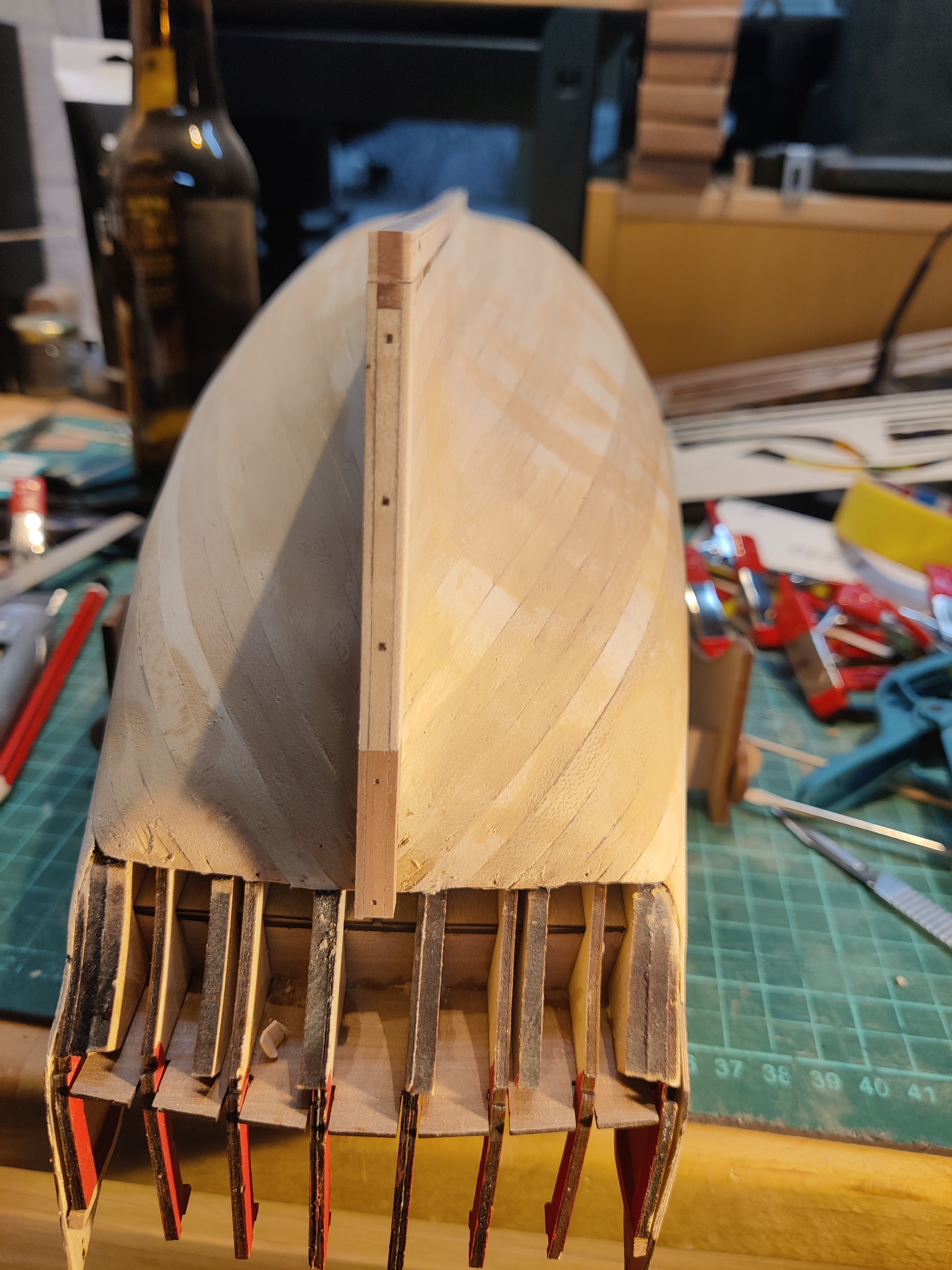
I started to draw a line parallel to the waterline and immediately realised that that was not going to work. Midships, the planks are vertical, but towards the ends, especially at the stern, the shape would require very broad planks to stay parallel with the waterline all the way.

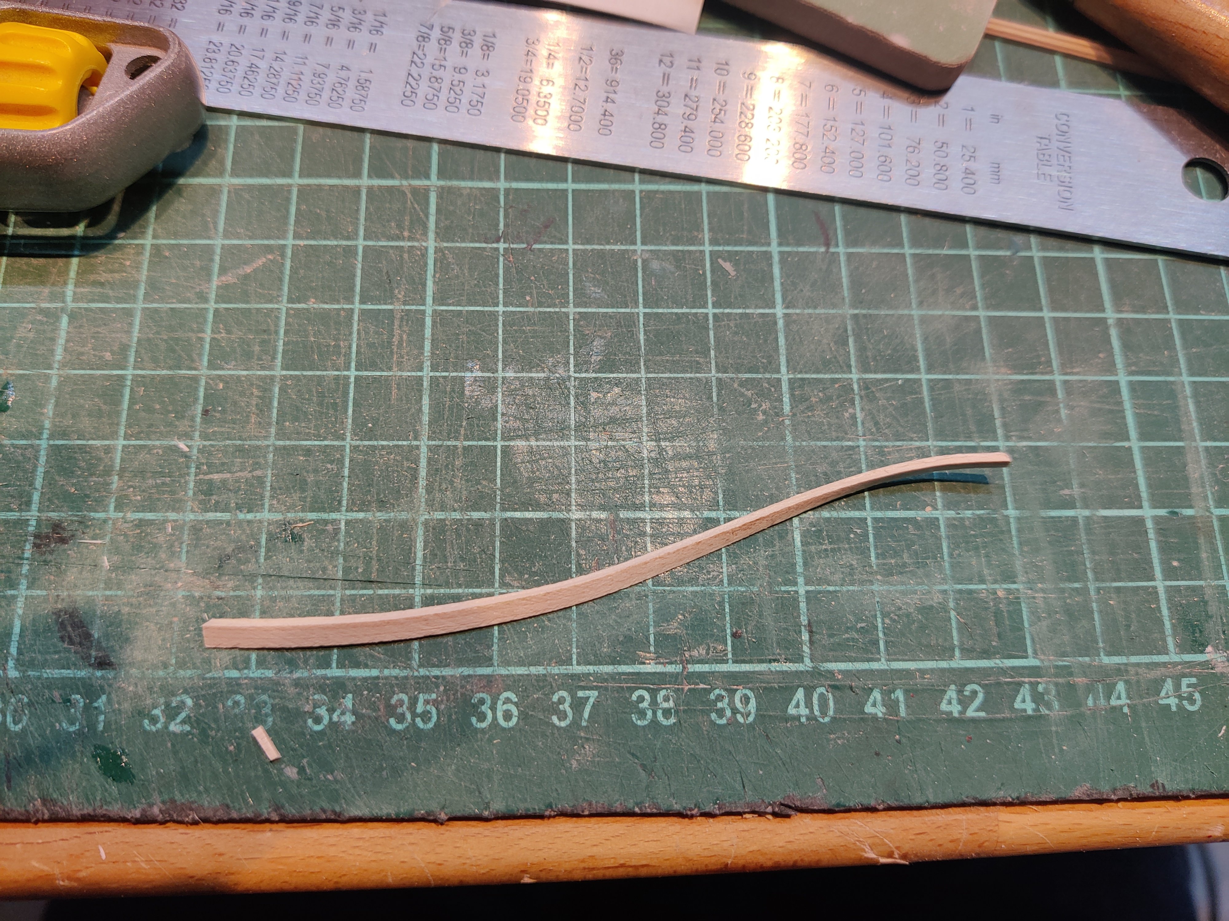
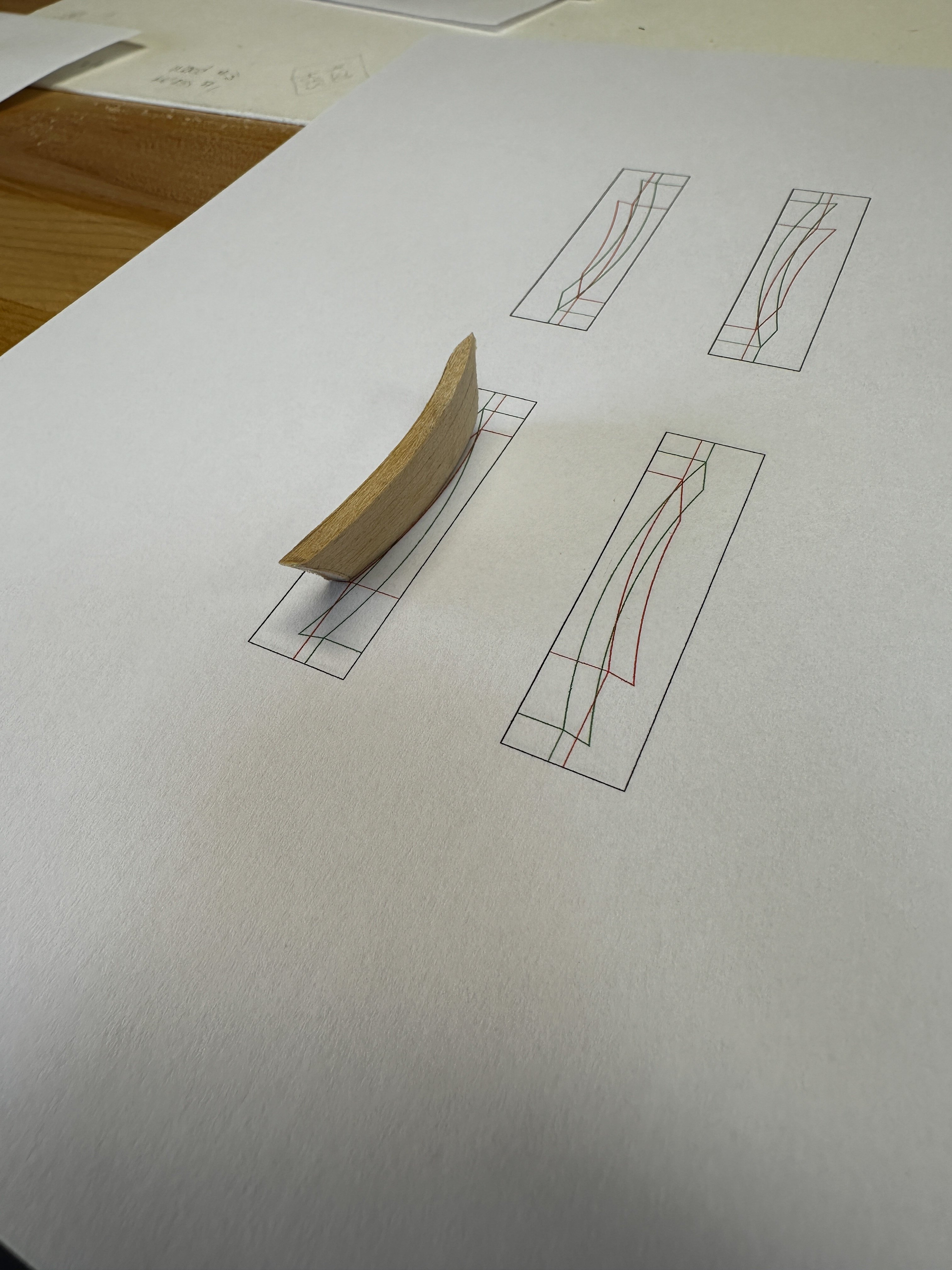
Instead, I took the time to map out even plank runs for the entire rest of the second planking. I measured at various places and printet out measuring templates to use to mark up the hull:
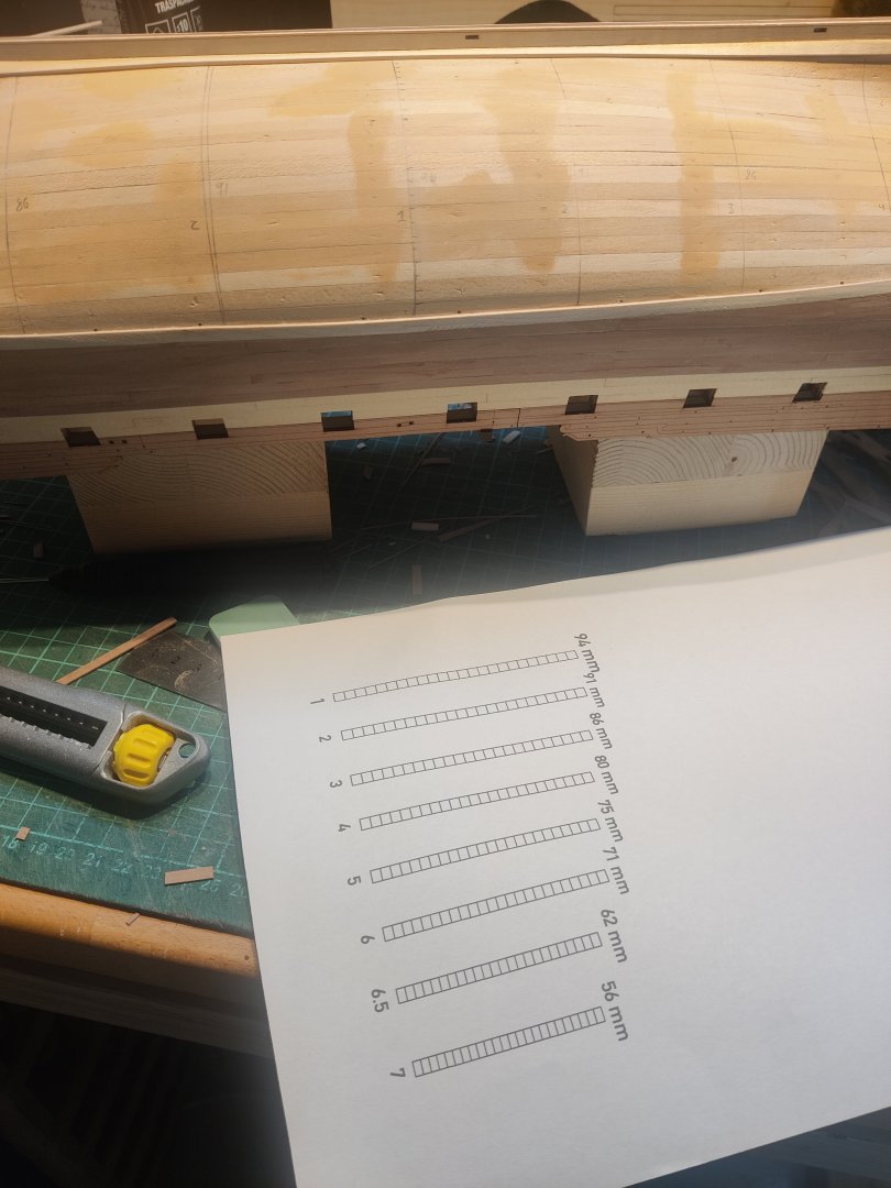
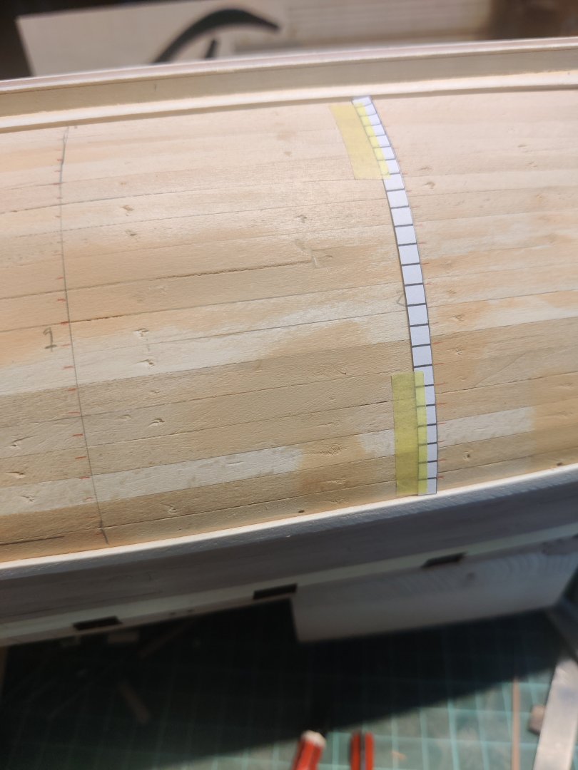
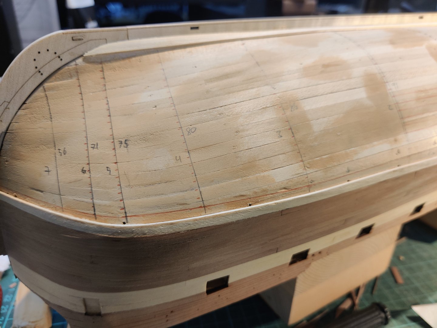
This took a few evenings.
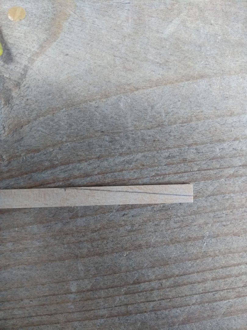
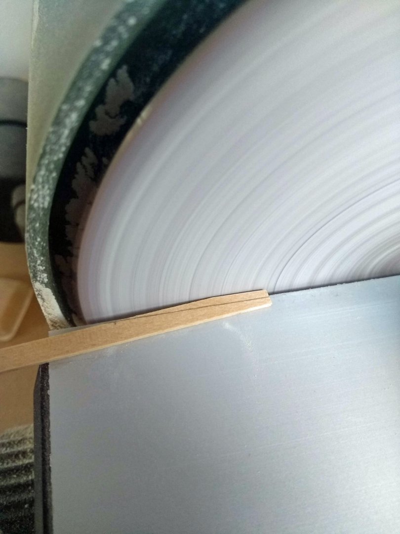
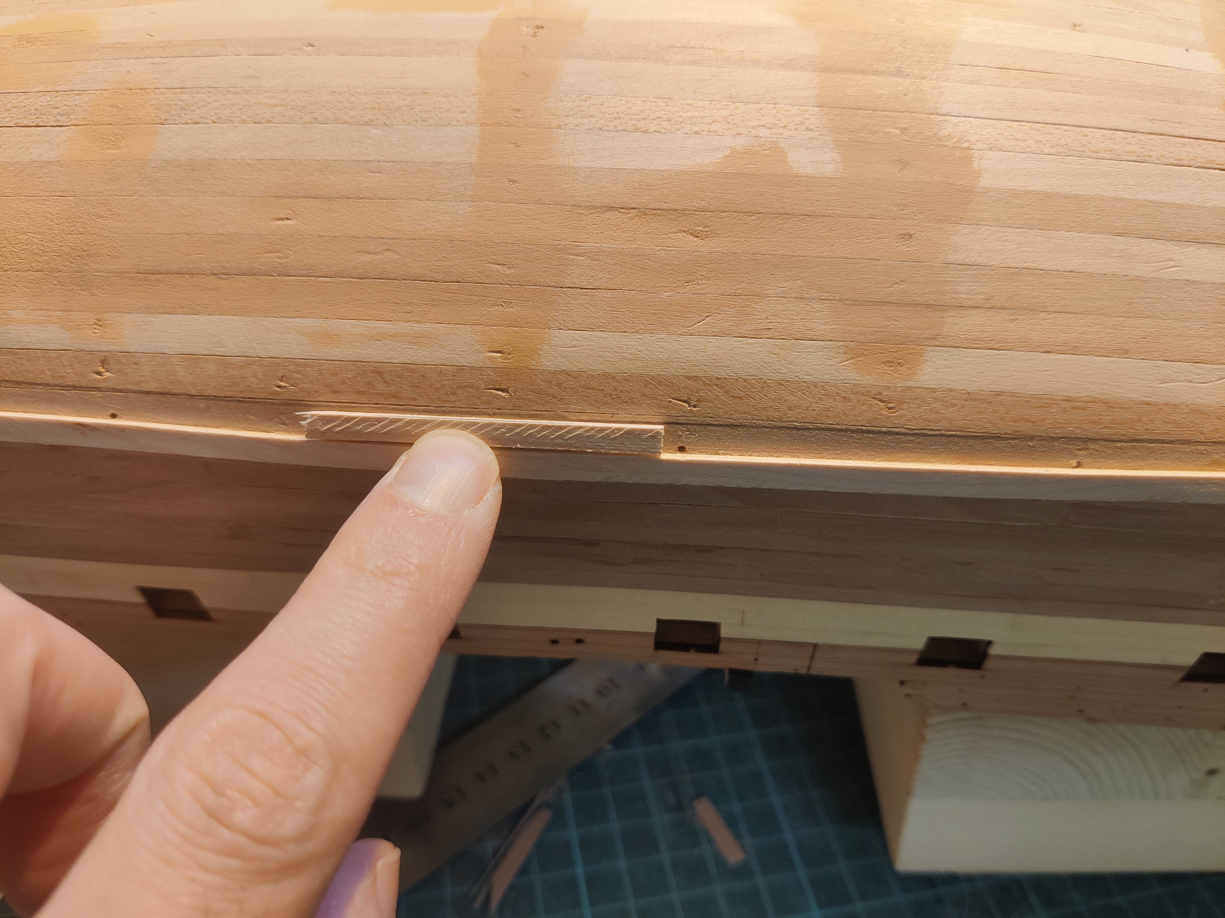
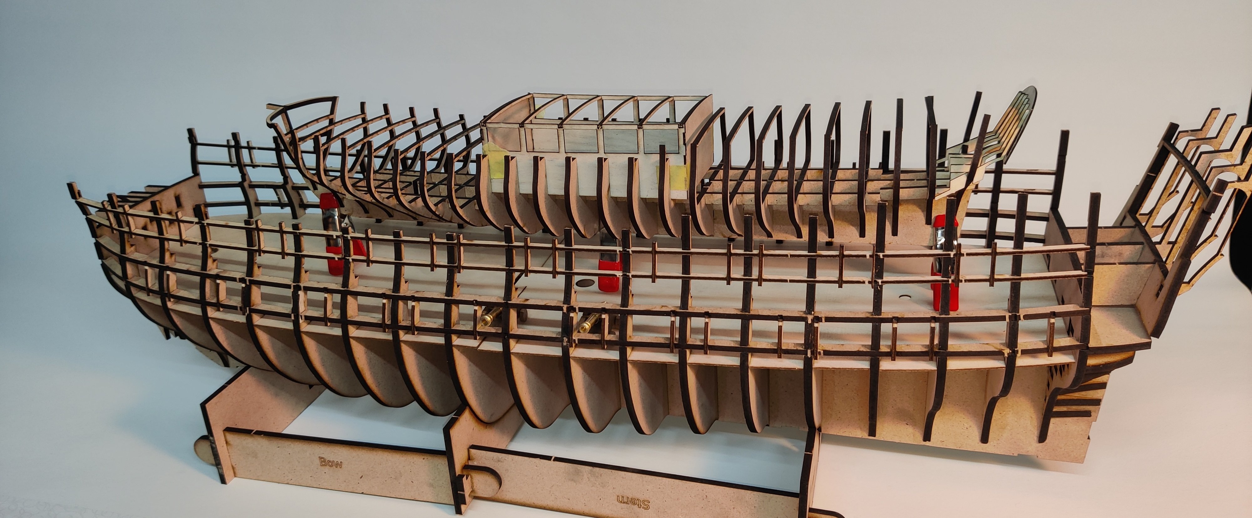
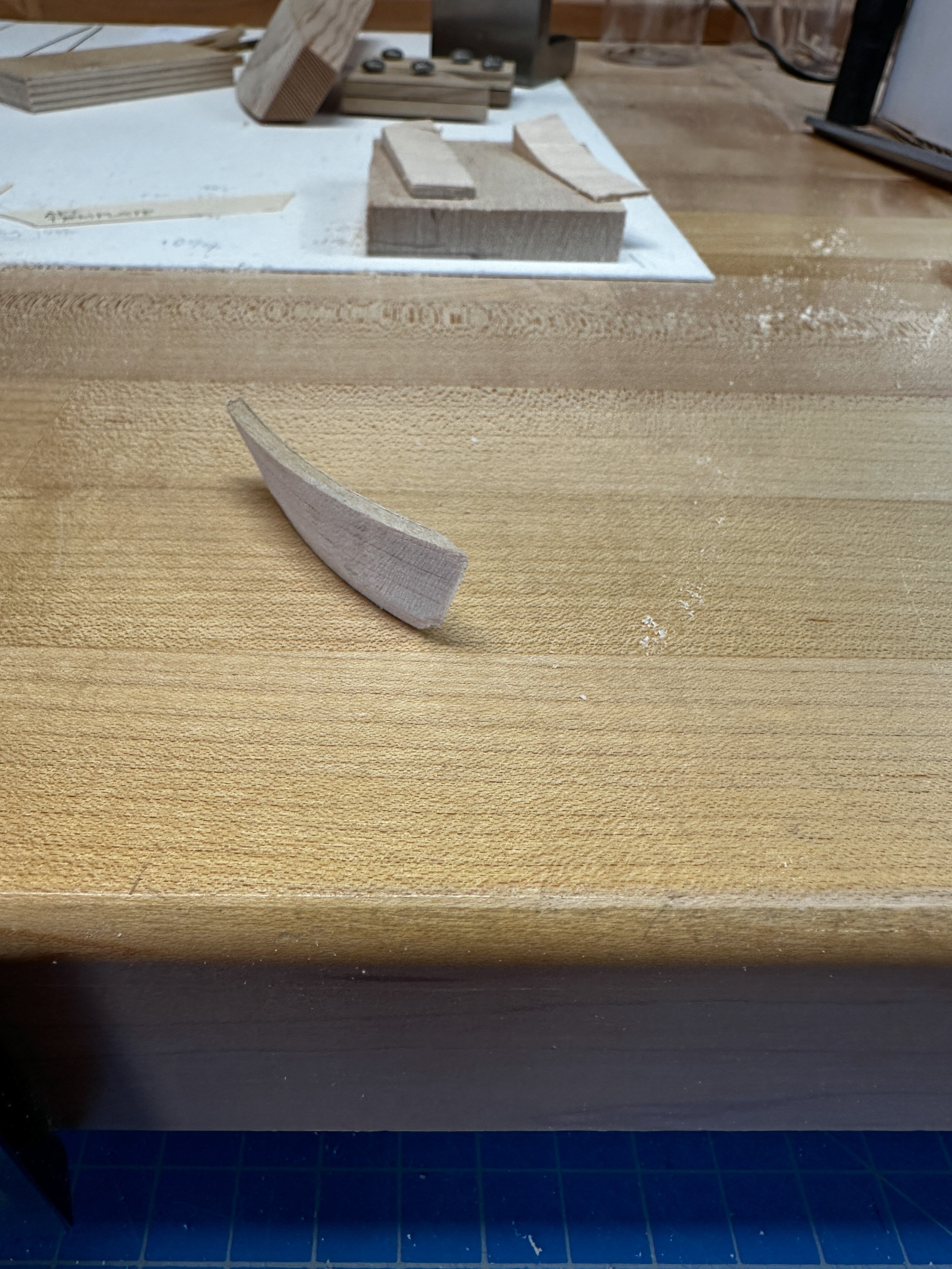
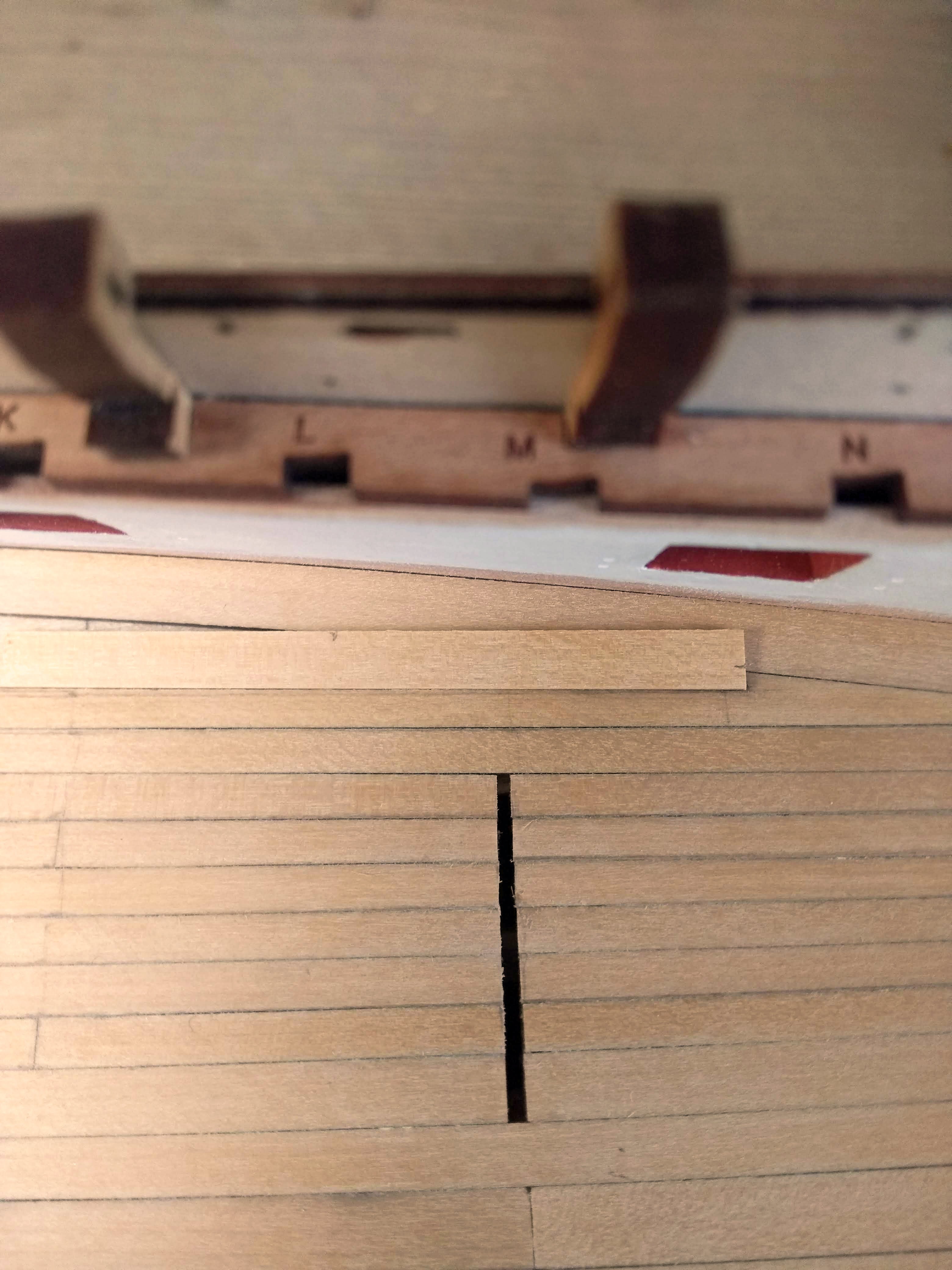
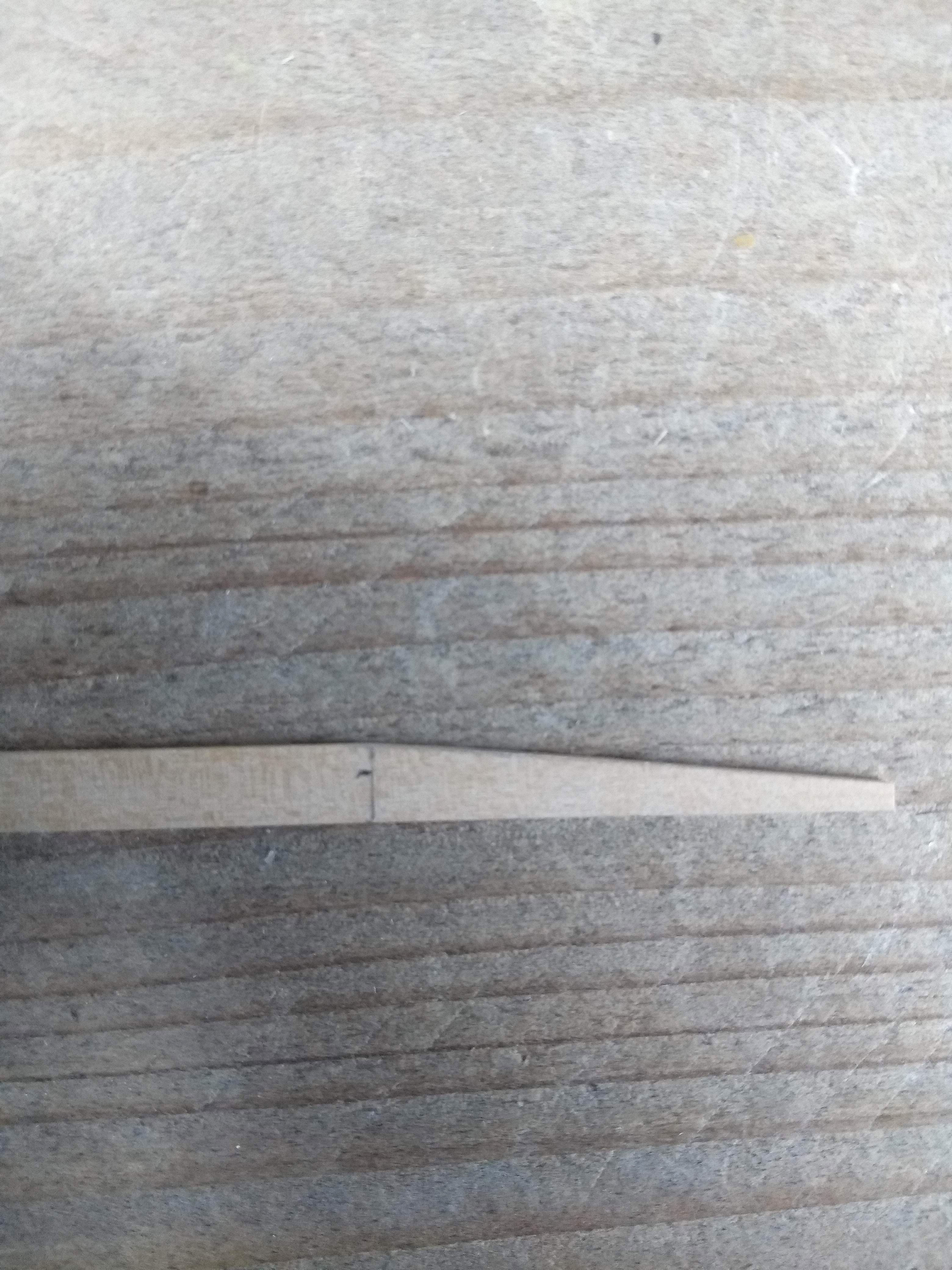
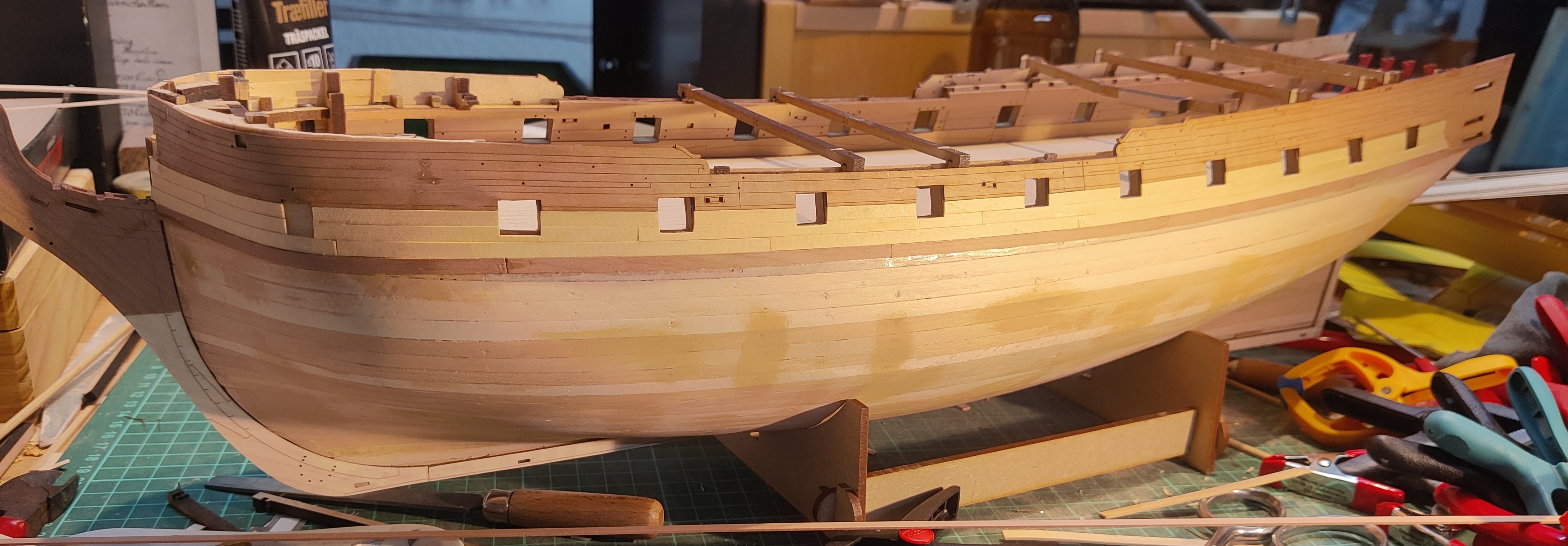
I have started with the next planks, the first are the most difficult ast they require more shaping and it should then become easier as I get along.

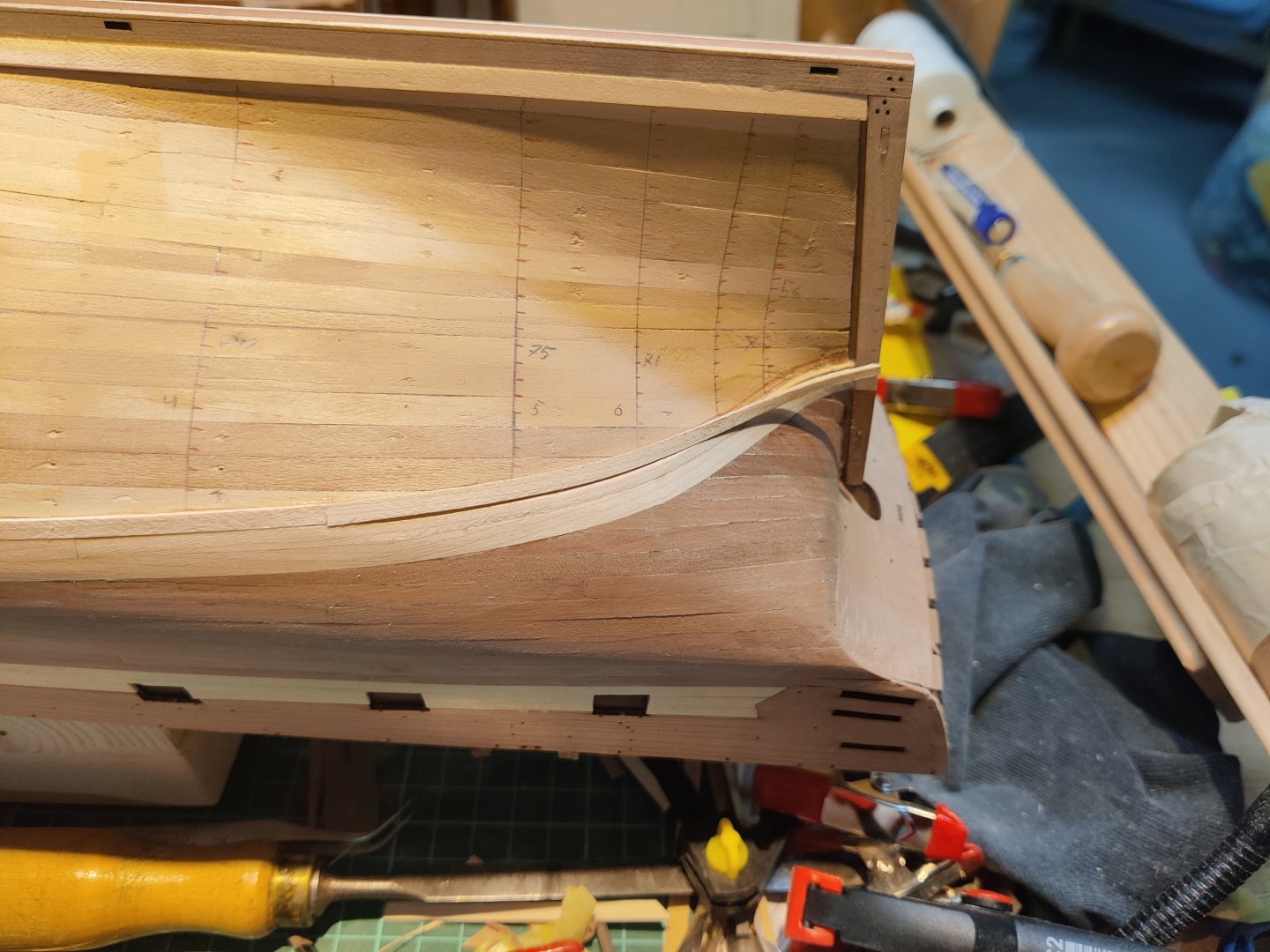

Including the first whole maple planks, I now have 3 on one side and 2 on the other. It takes close to an hour per plank right now so this is going to take a while. I have 25 total on either side. 😅
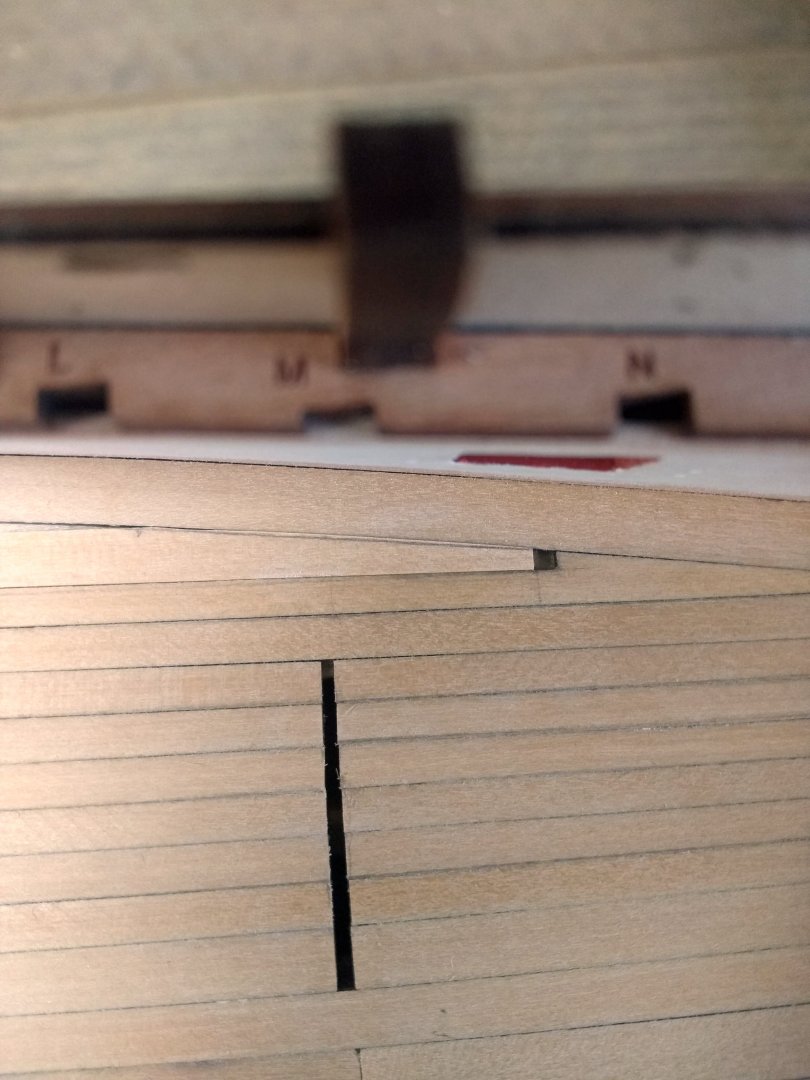
I can see that it wont be totally perfect, but sanding removes most of the imperfections that are there initially and the maple is very even i colour and texture. When the seams are good, they are virtually invisible, which gives a bit of tolerance for the planking job i need to achieve. I will do my best, but it is good to have a bit of wiggle room.
BR
TJM
- CiscoH, hollowneck, Beckmann and 5 others
-
8
-
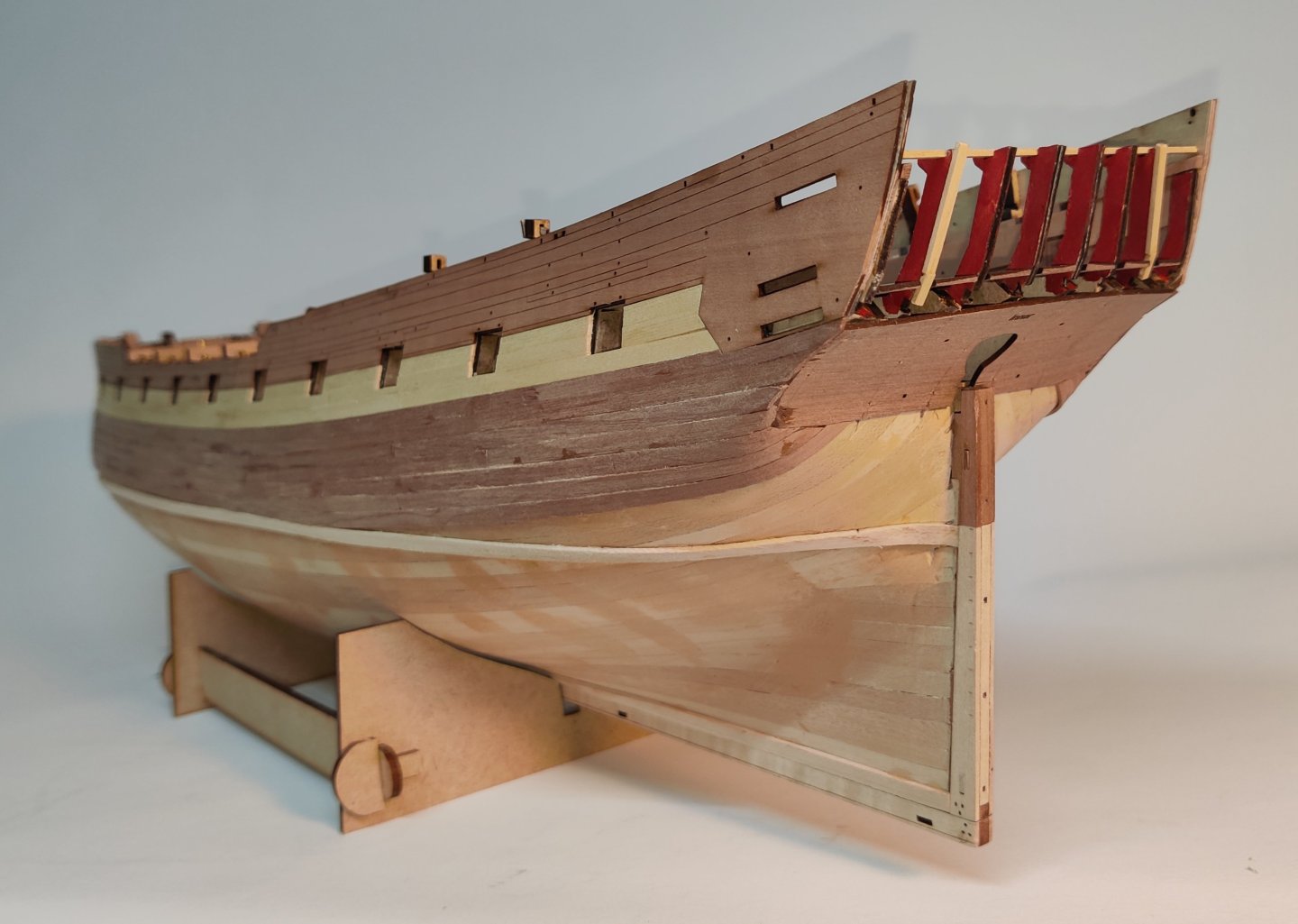
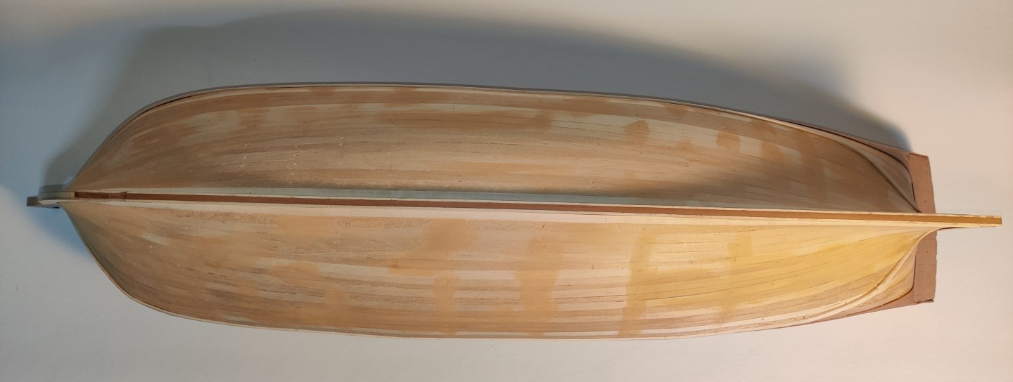
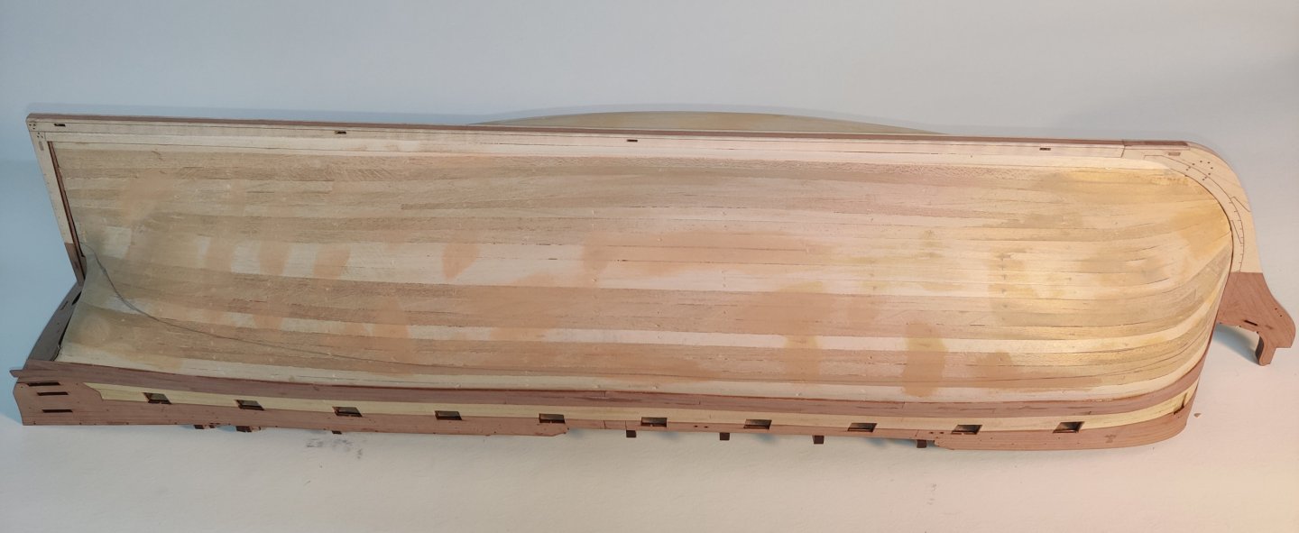
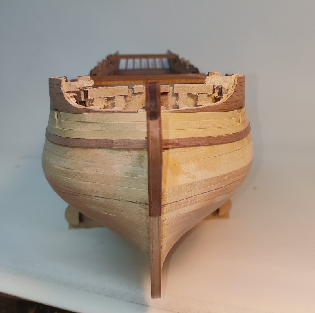
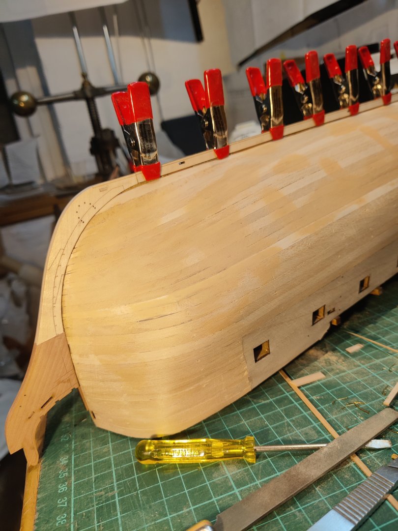
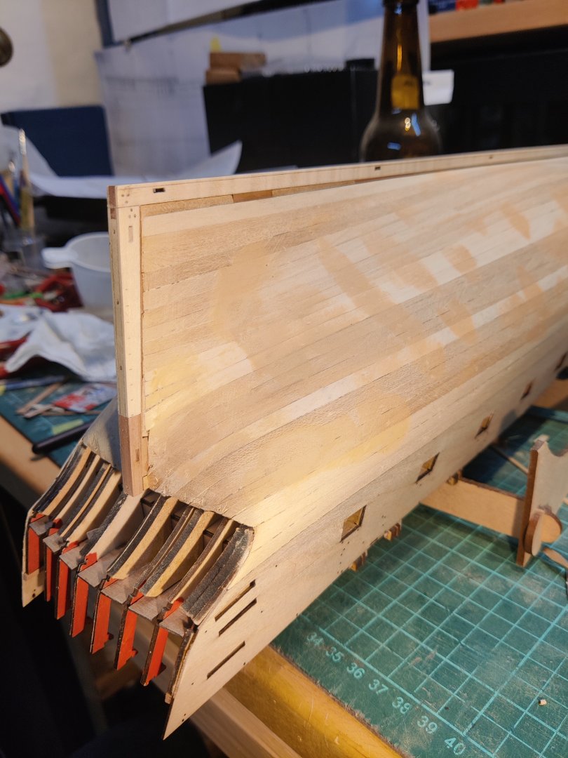
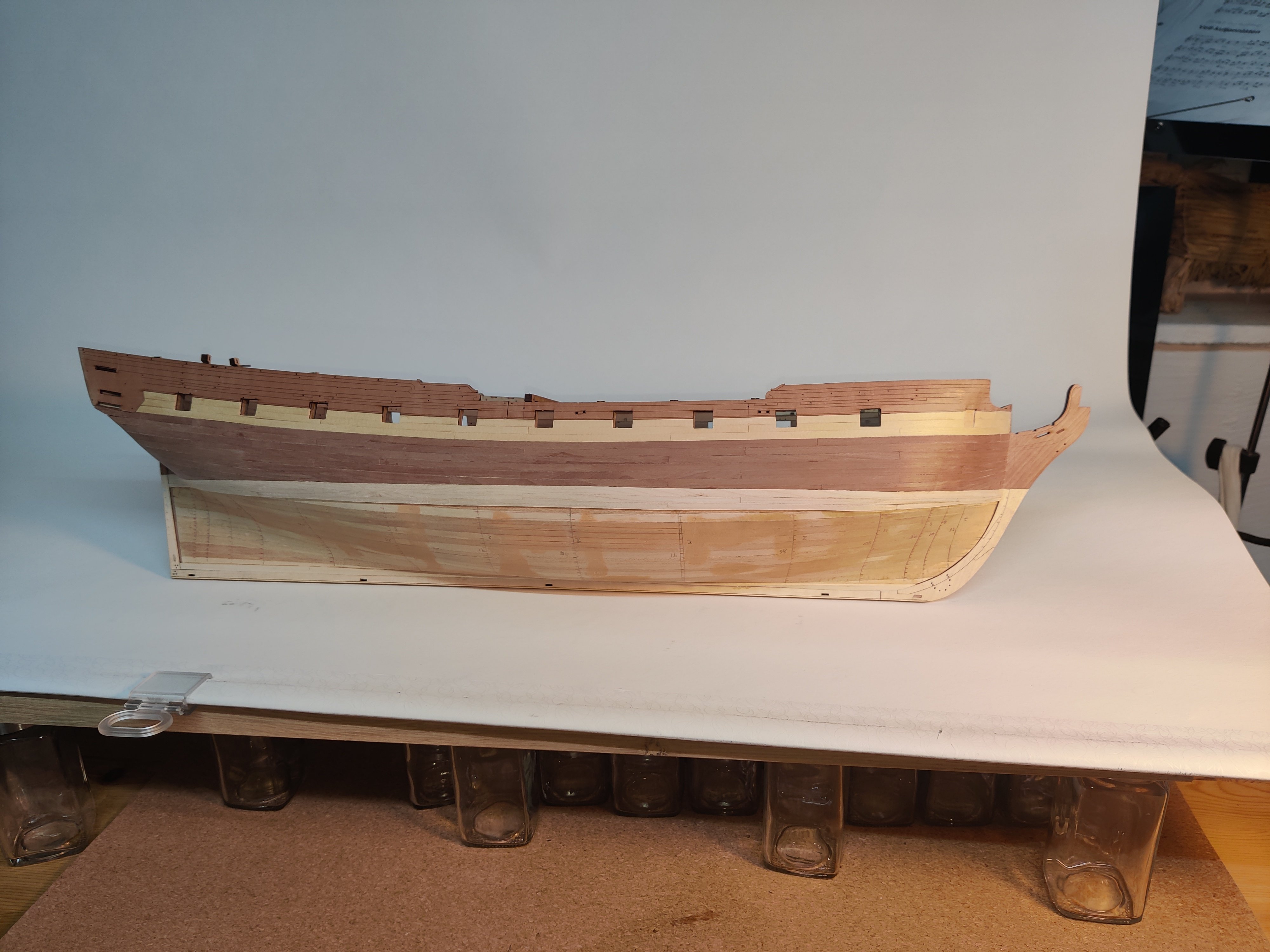
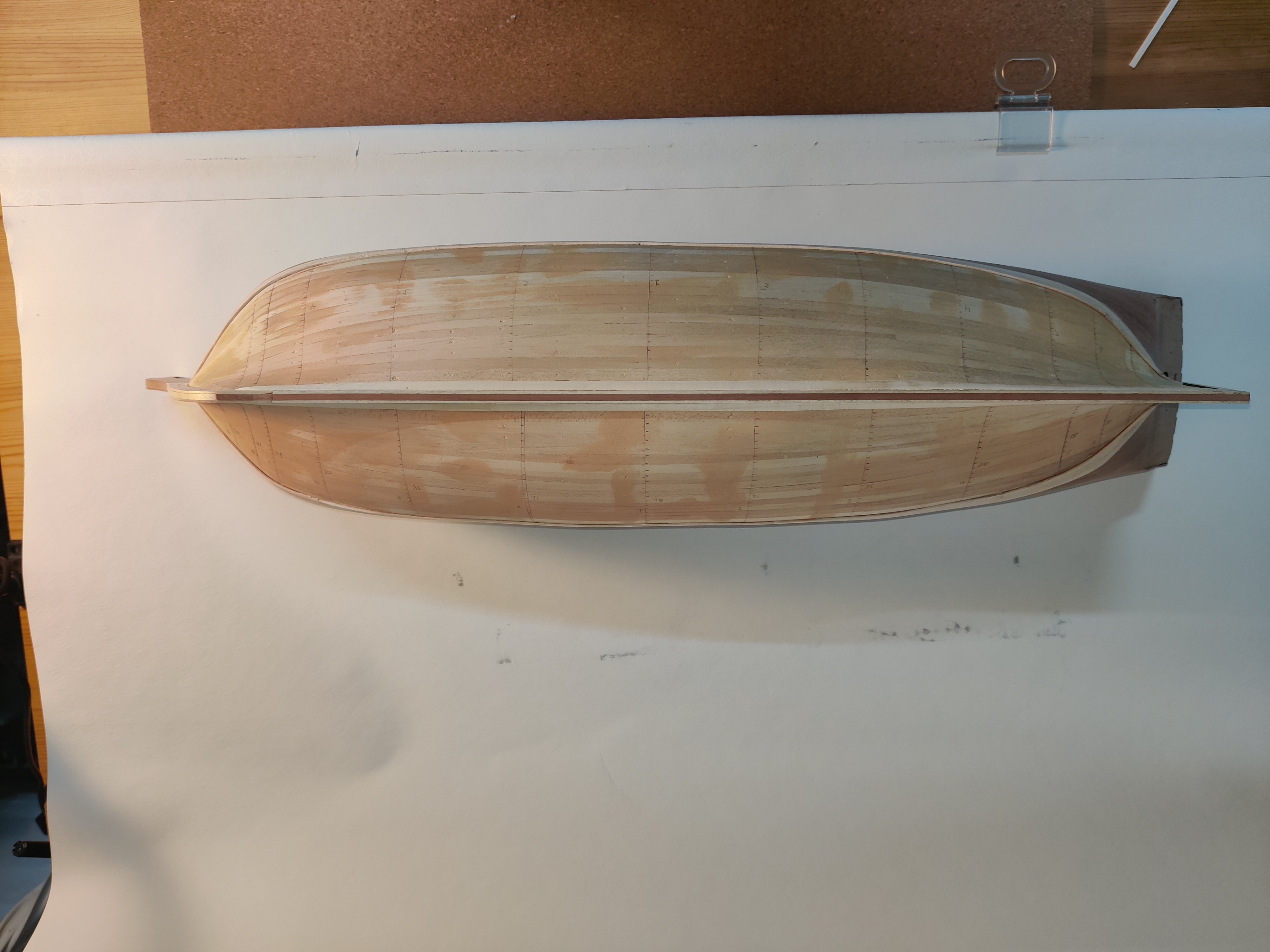
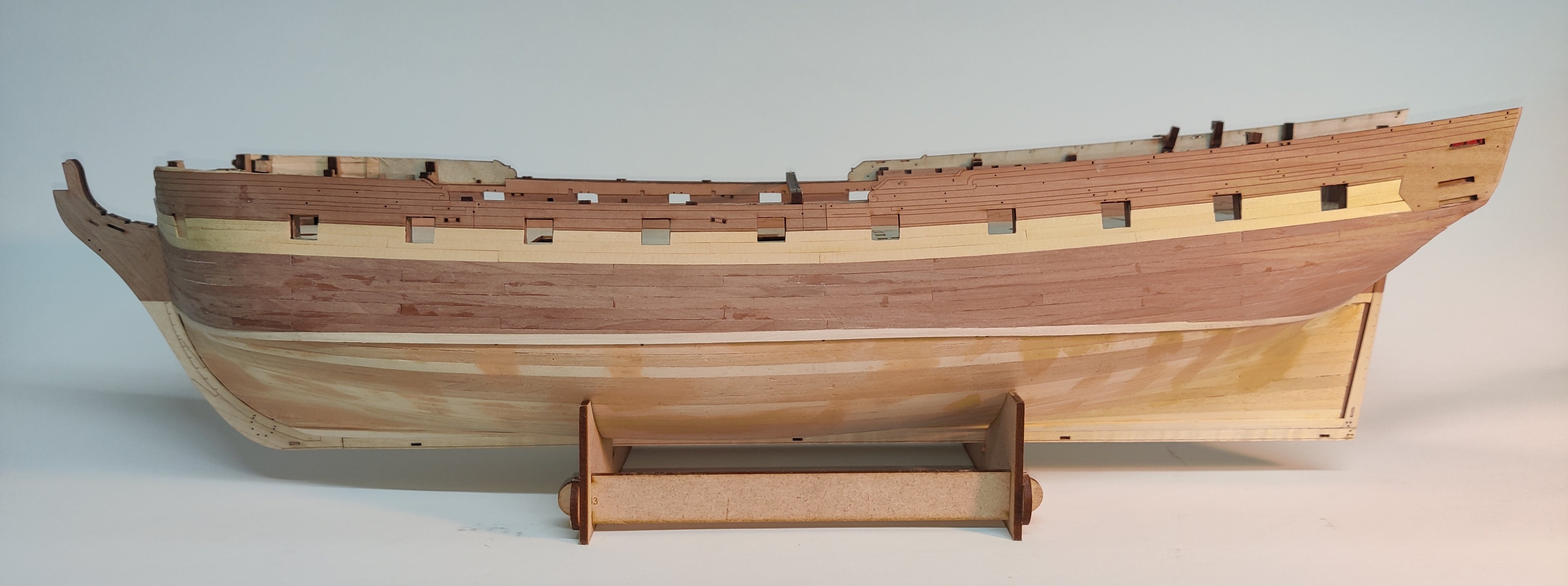
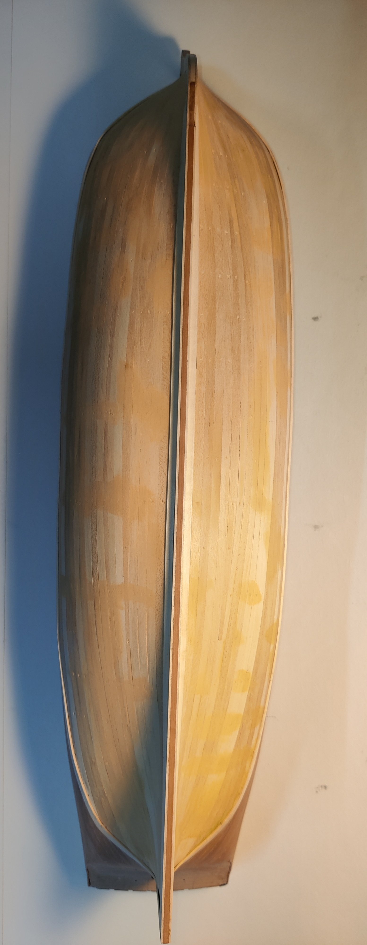
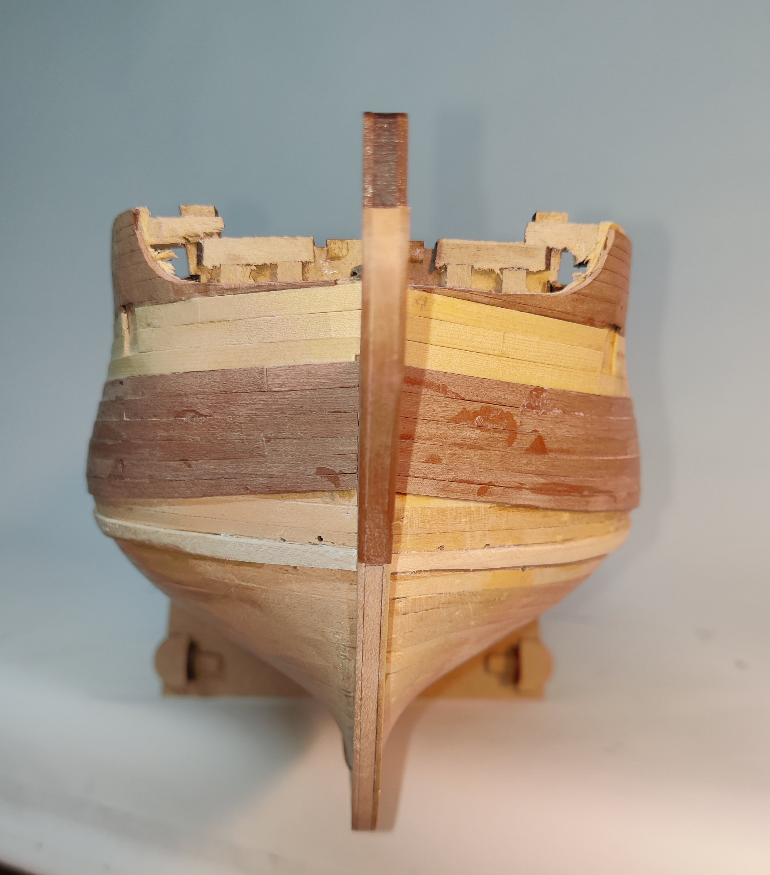
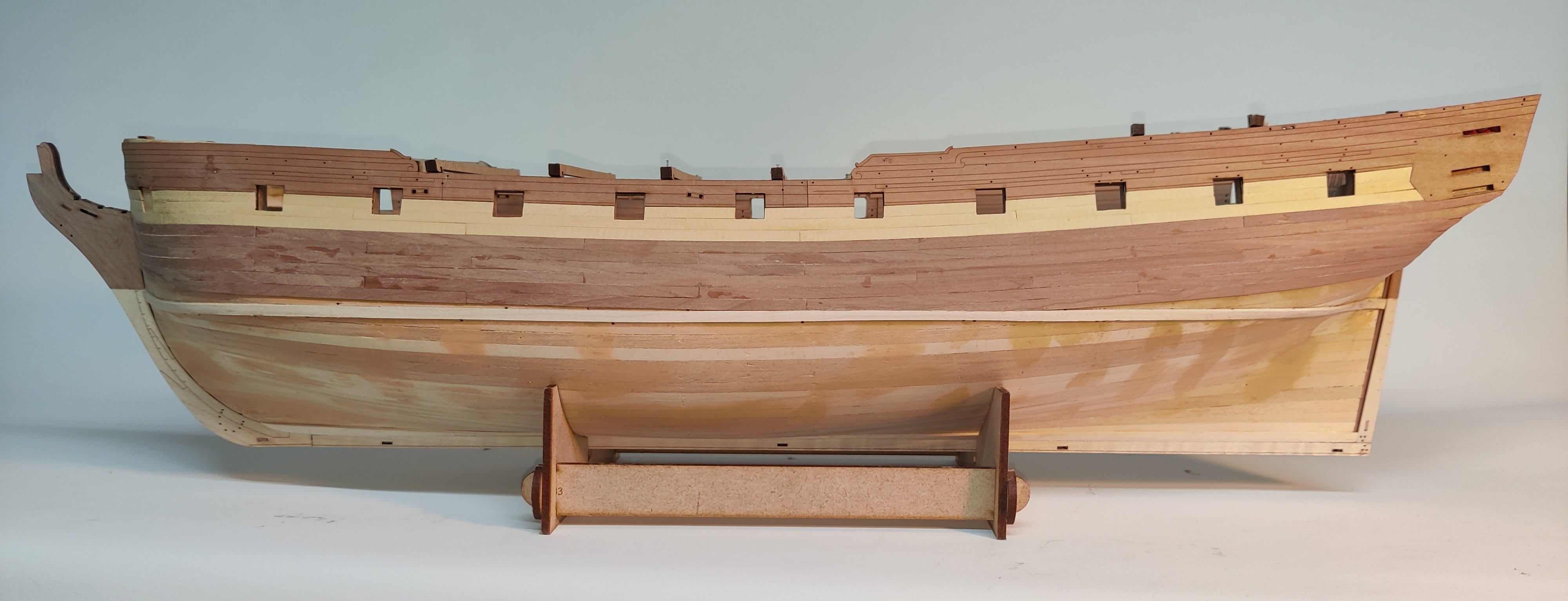
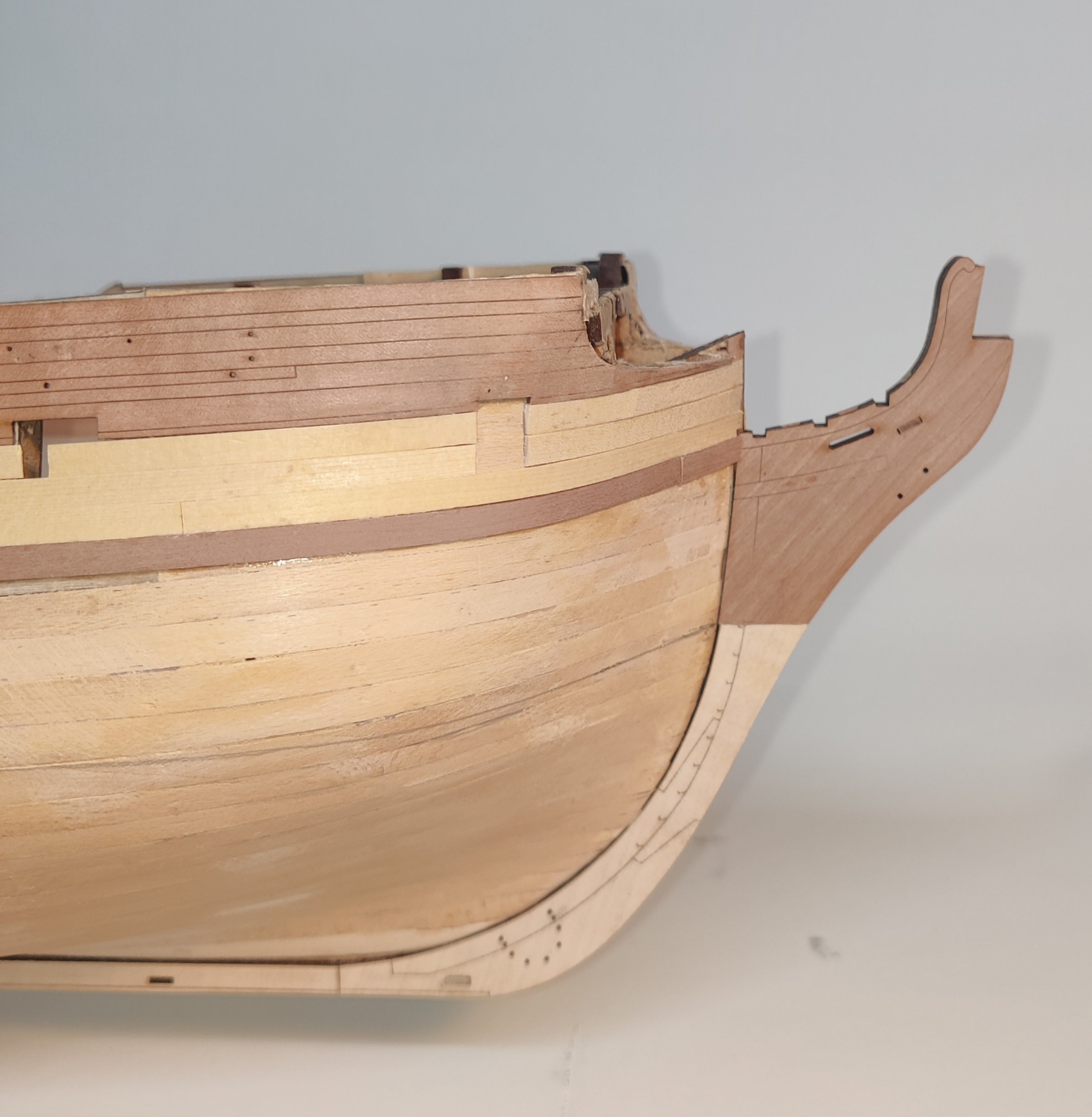
Log entry 19 - upper part of second planking done
Hello everyone, and thanks for the likes.
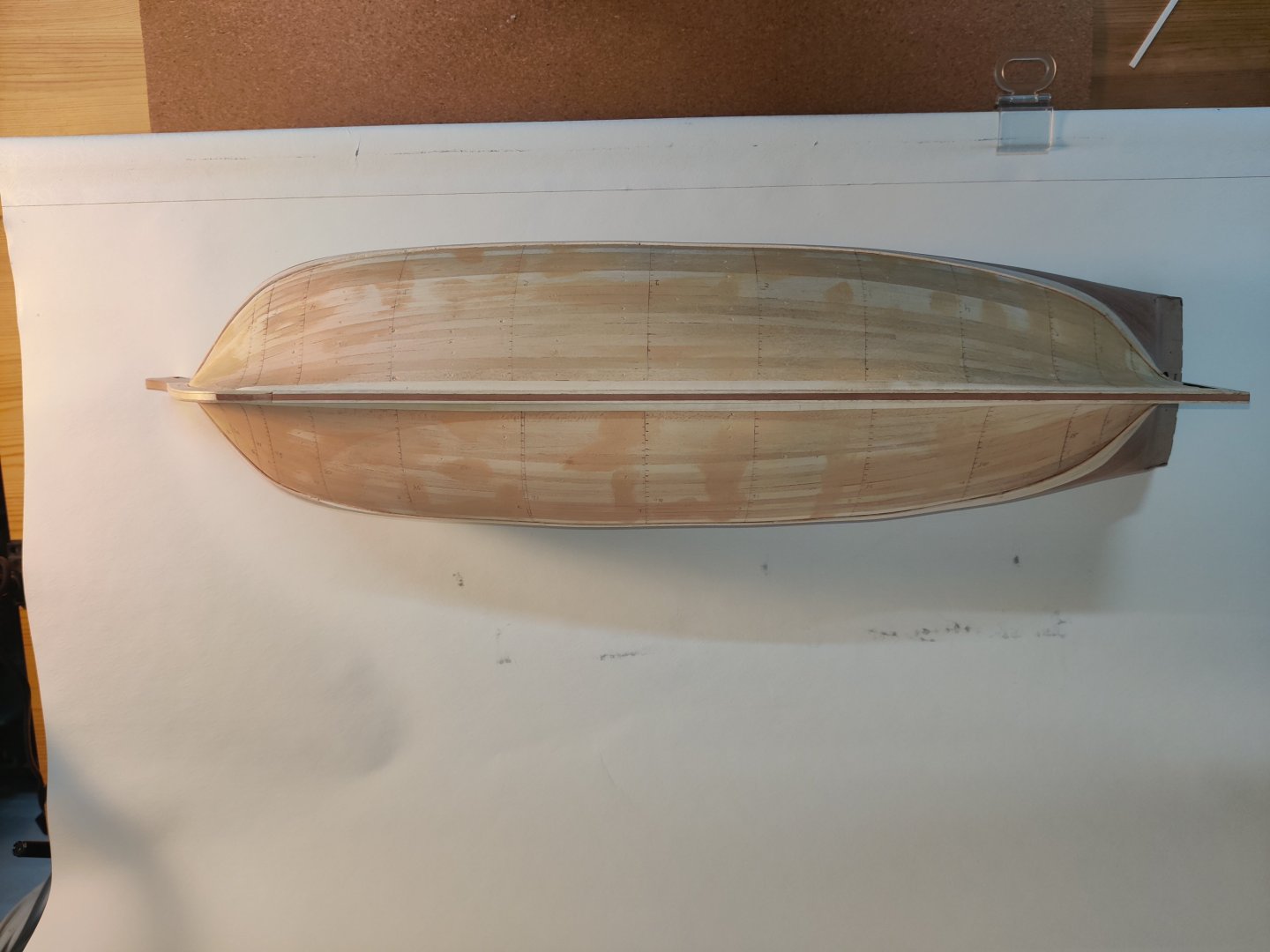
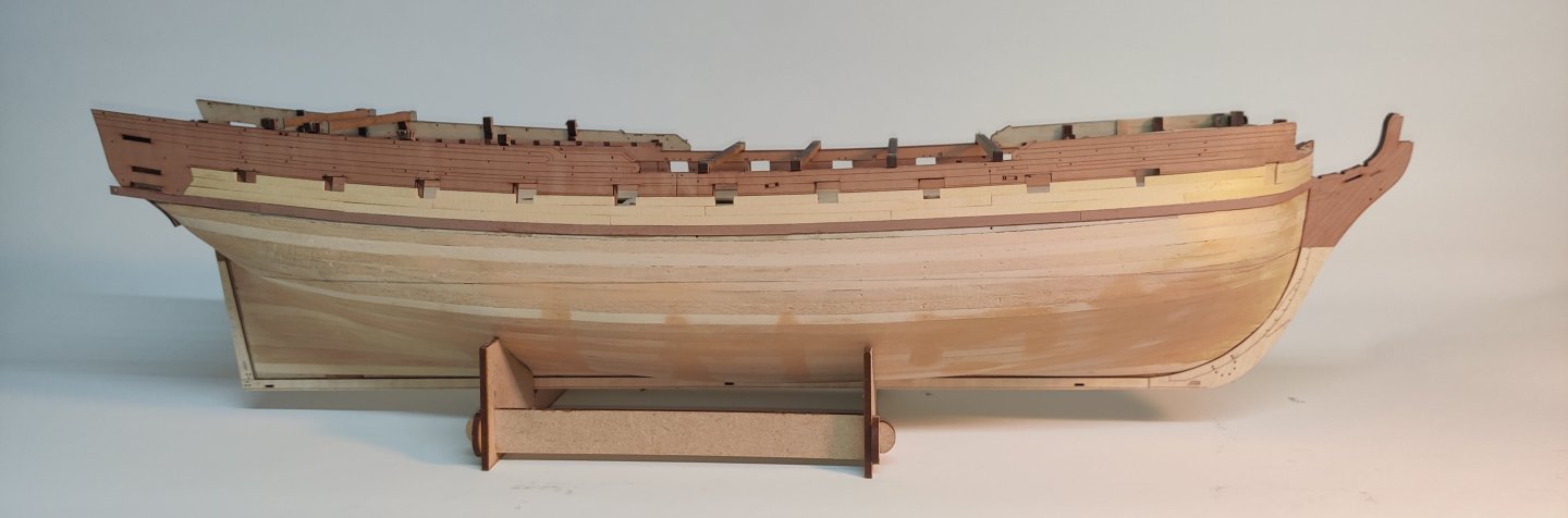
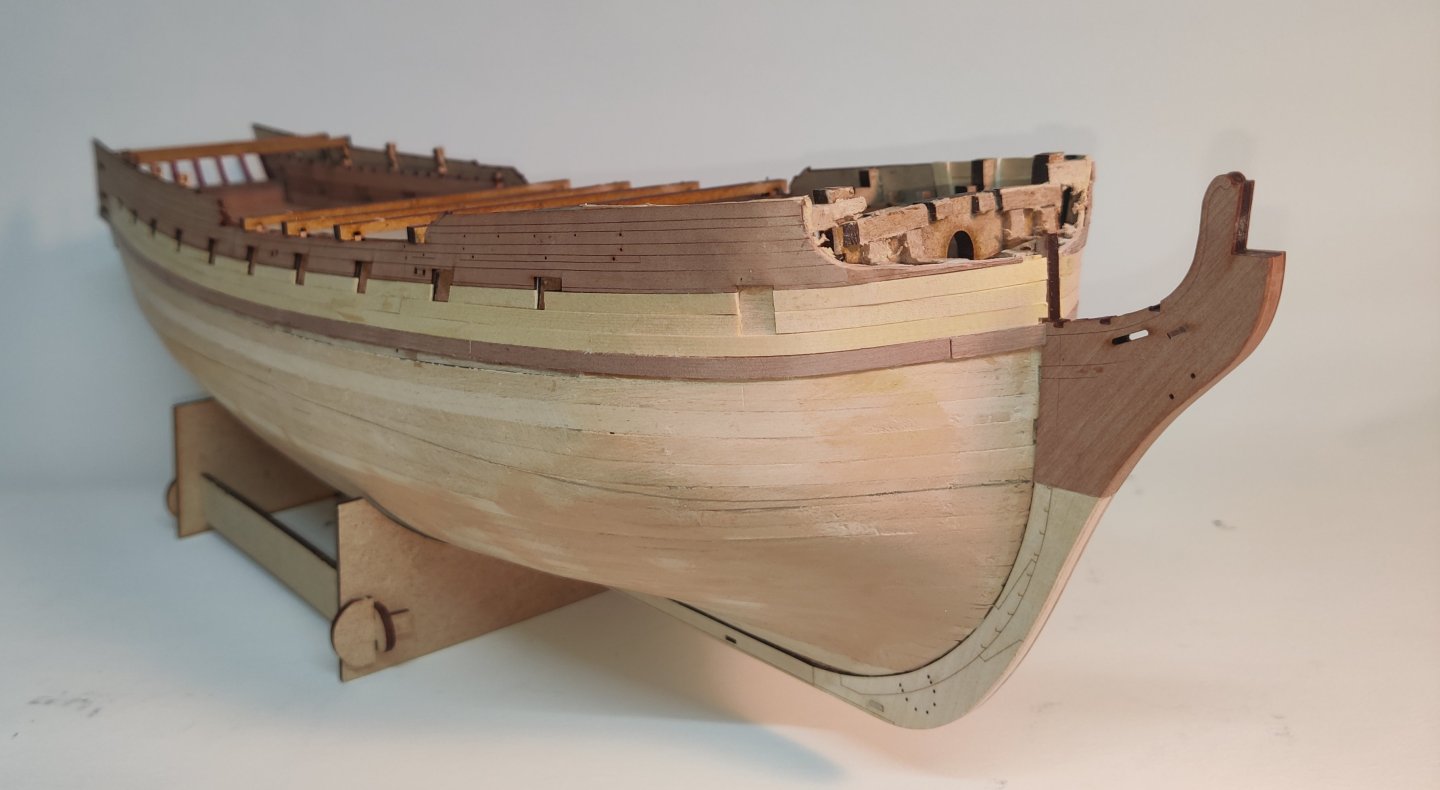
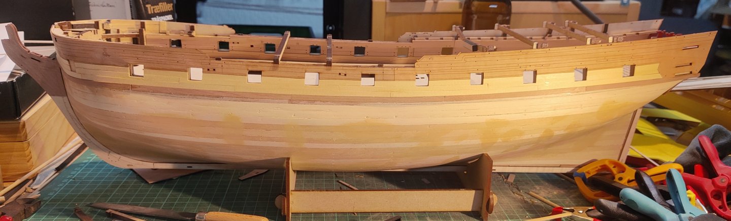
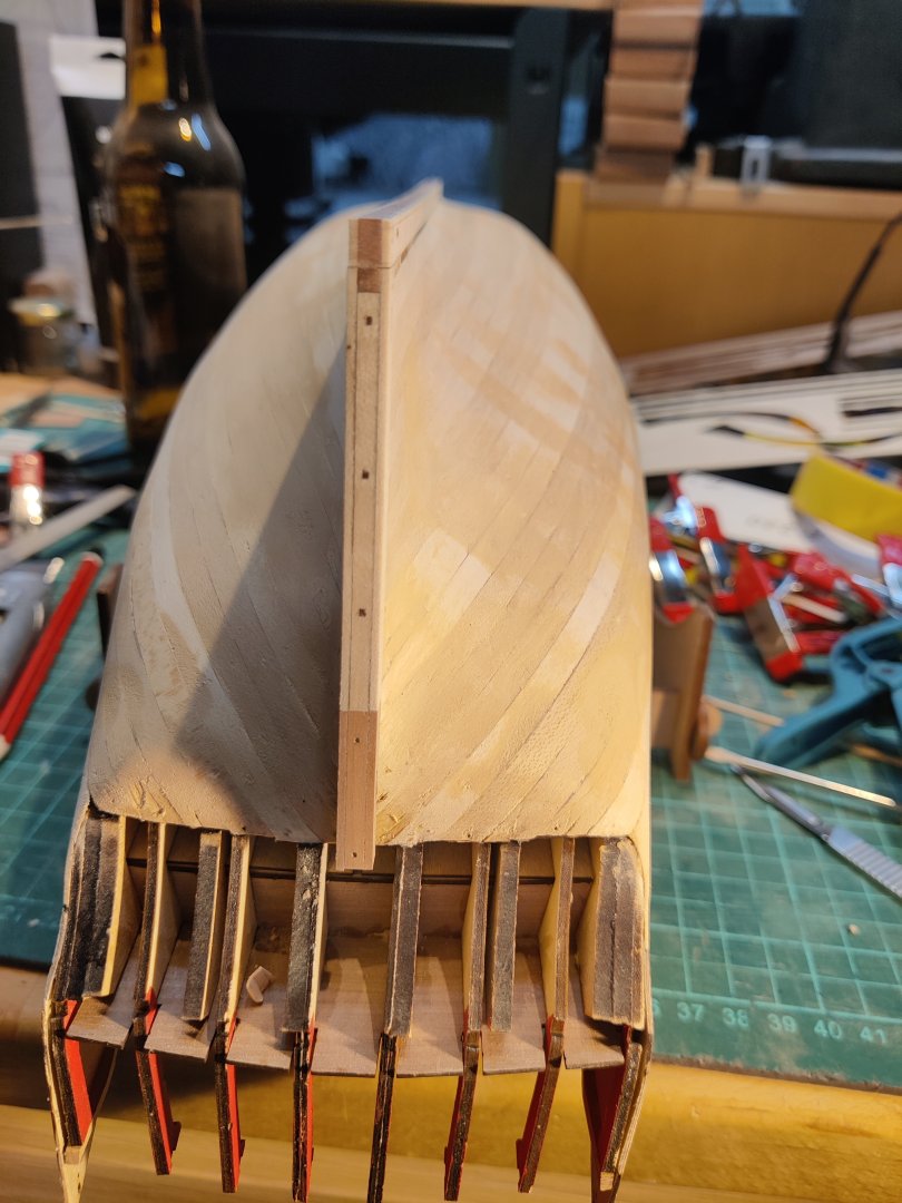
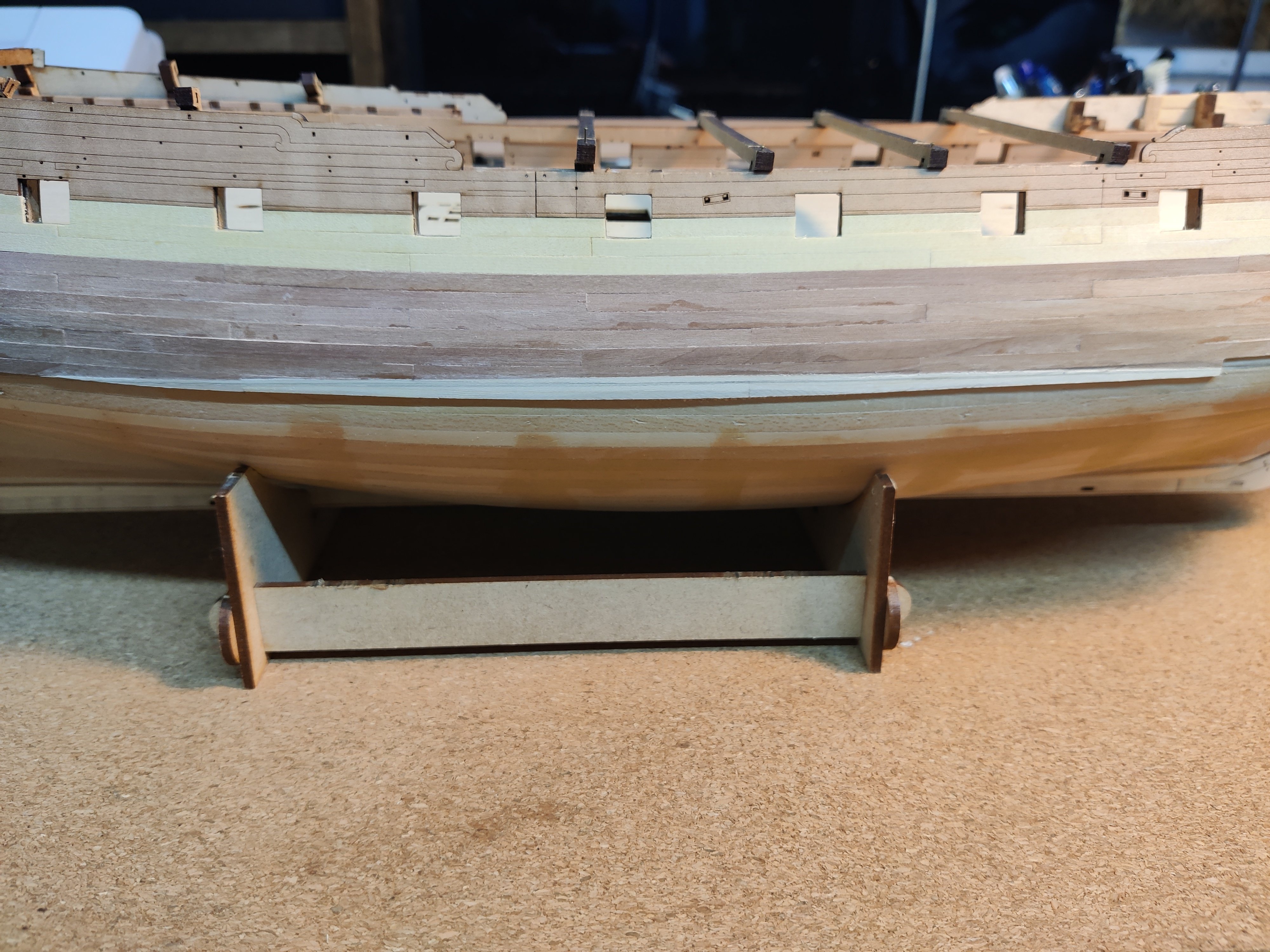
I have now planked down to the waterline on both sides, which is a kind of halfway milestone for the second planking.
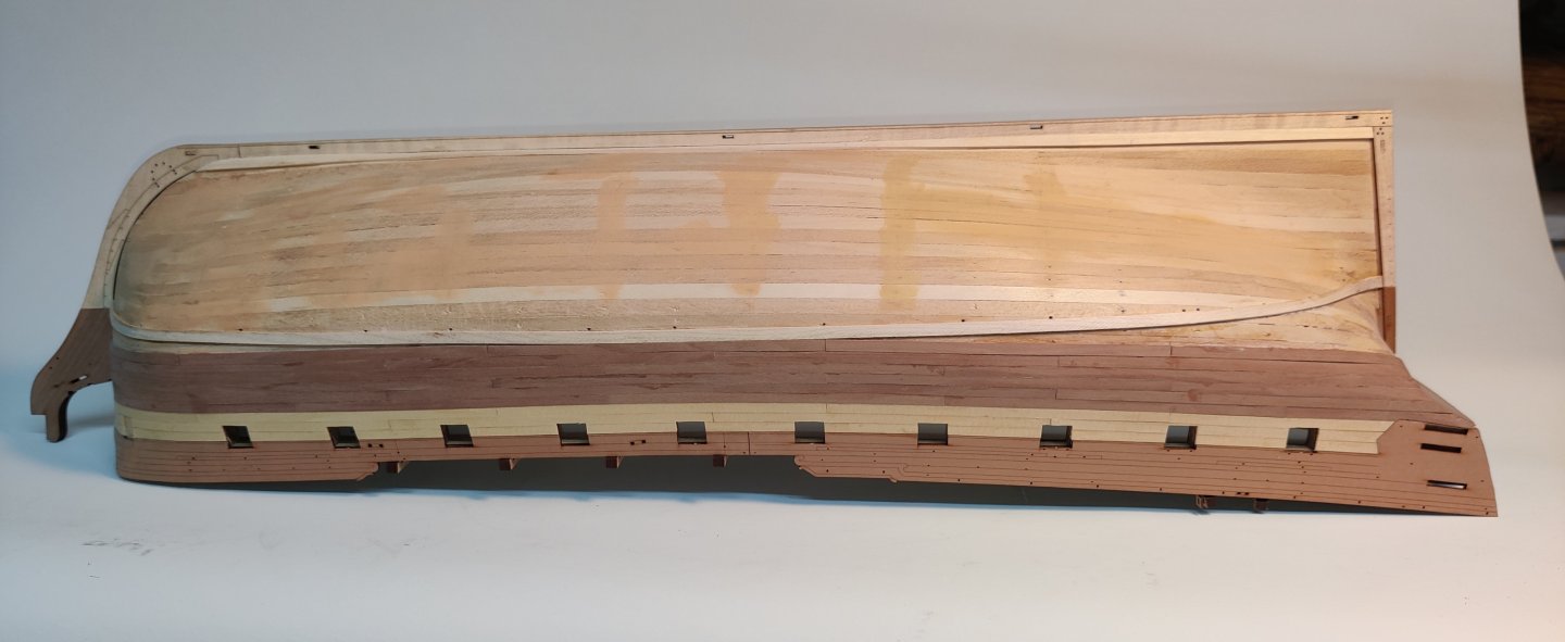
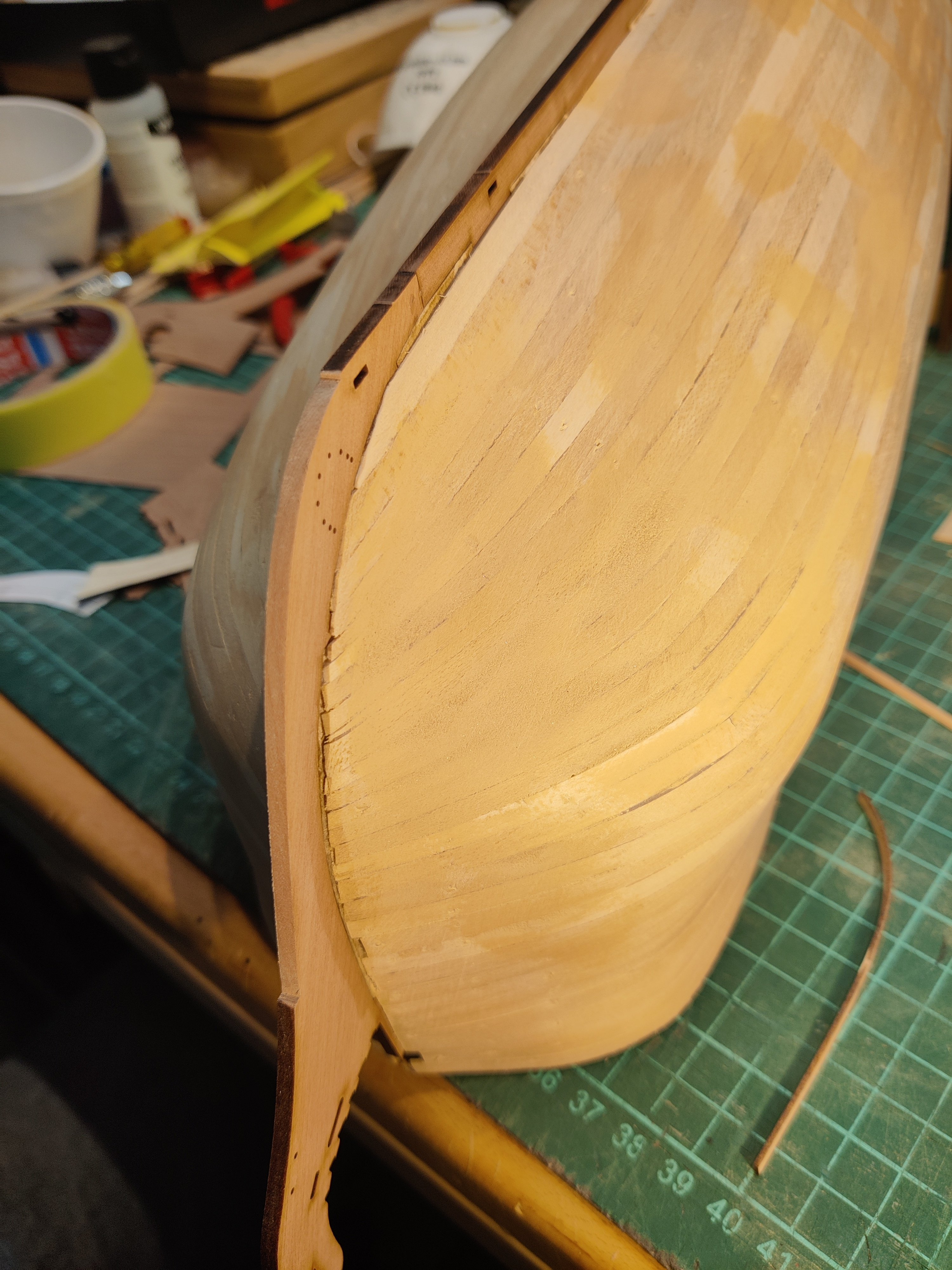
Here's both sides:
So far, I am happy with by wood choices and am exited to see the final form of the hull taking shape. I have roughly sanded the starboard side and think it will turn out very nice after a good deal more sanding.
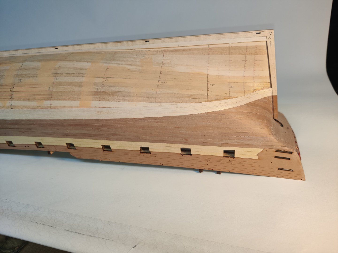
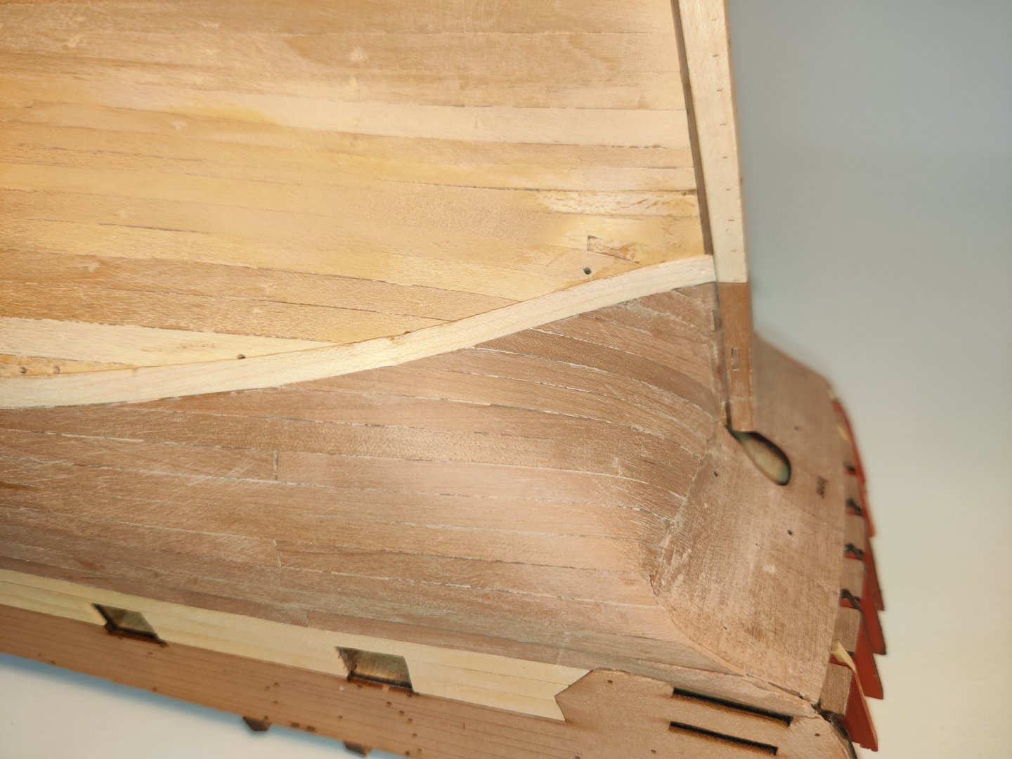
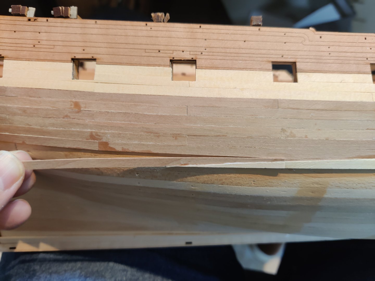
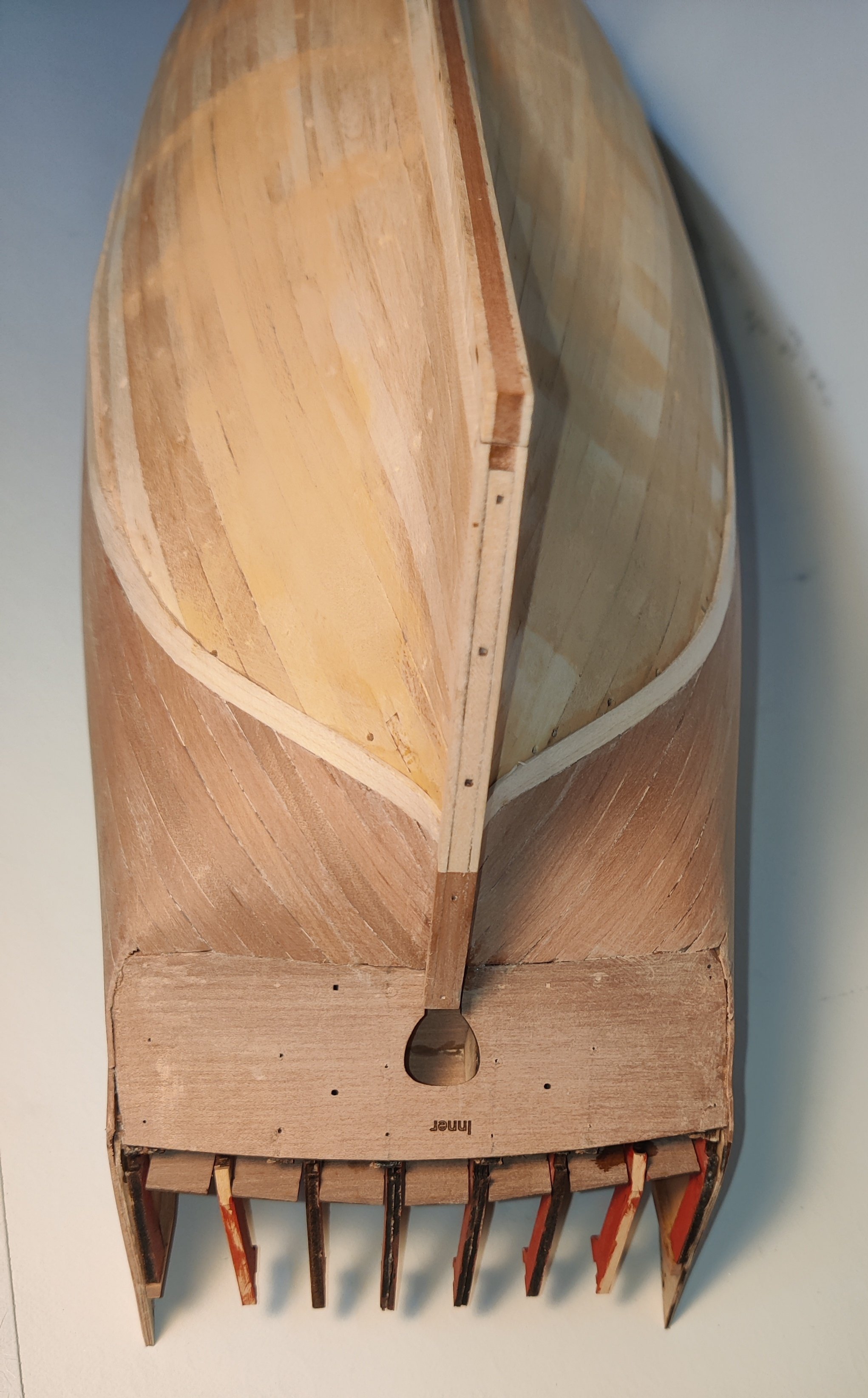
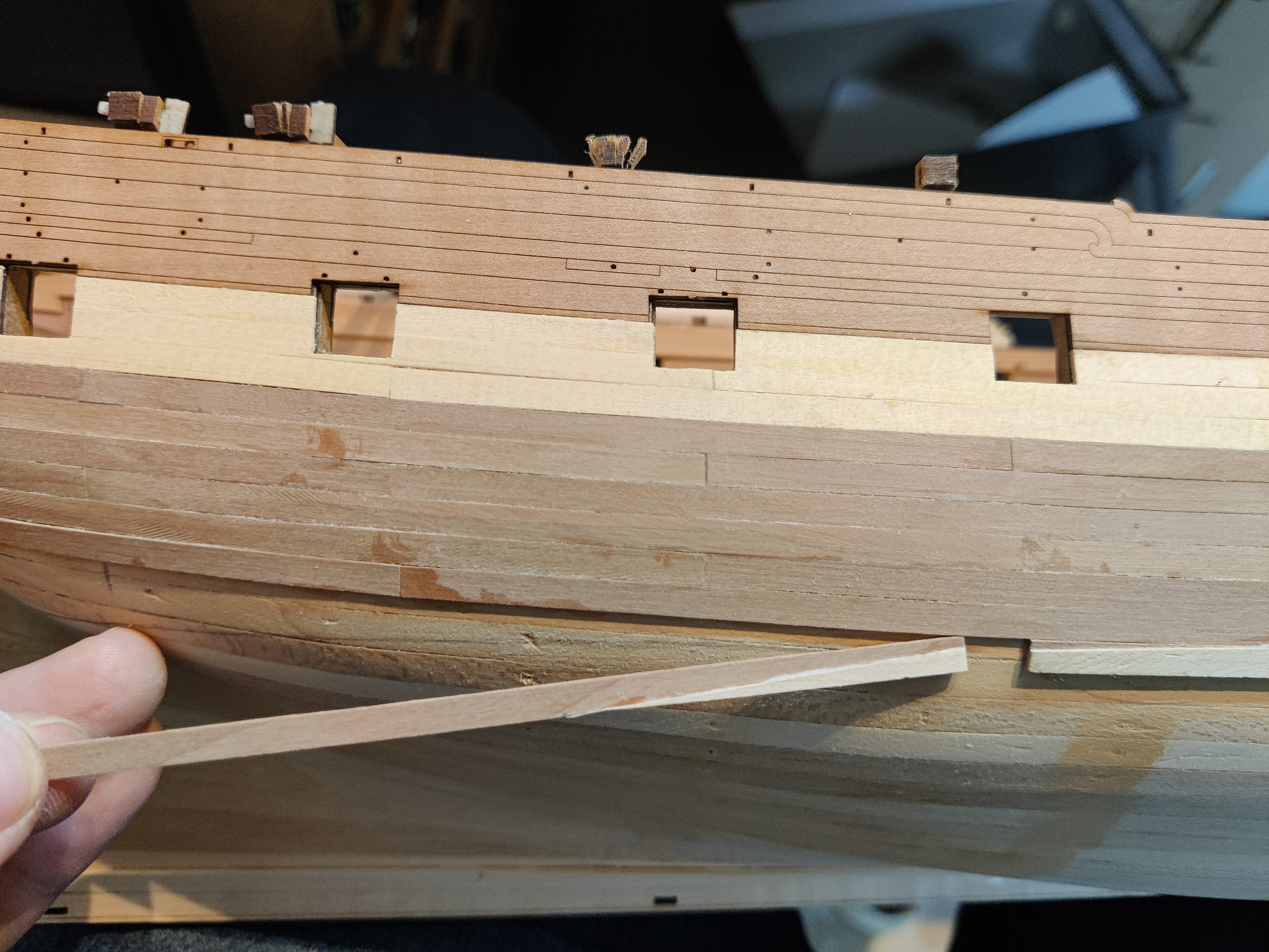
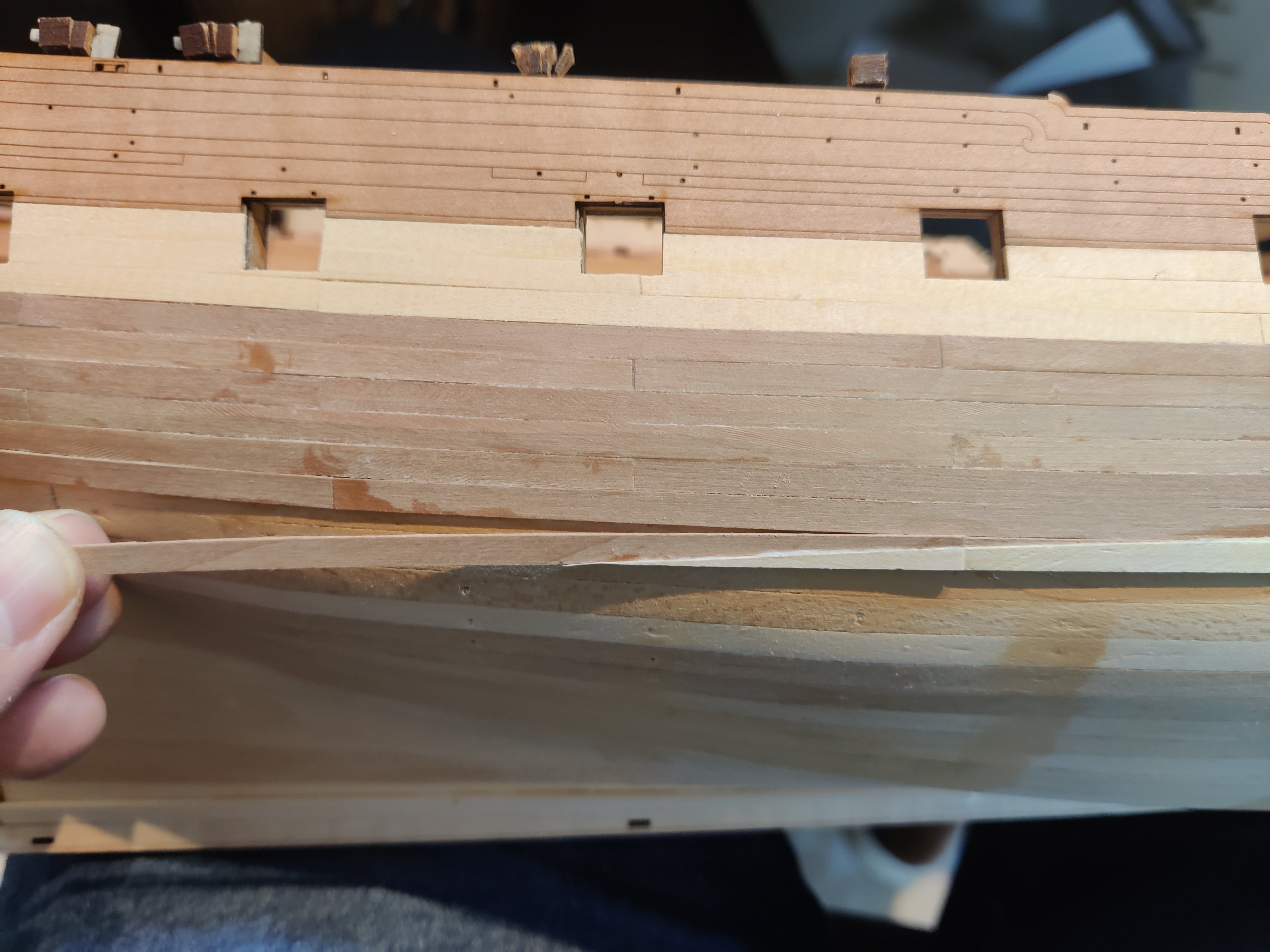
Here's a few close-ups (showing all the little imperfections and scratches - many will disappear later with sanding):
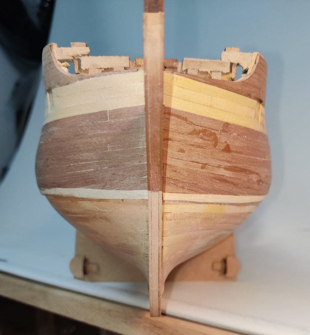


From the end on shots, it may appear as if the waterlines on either side are not at the same level - that is just a trick of the angles! They are at exactly the same level, I did not modify the height of the waterline marker at all when I drew them on! In real life, it looks fine.
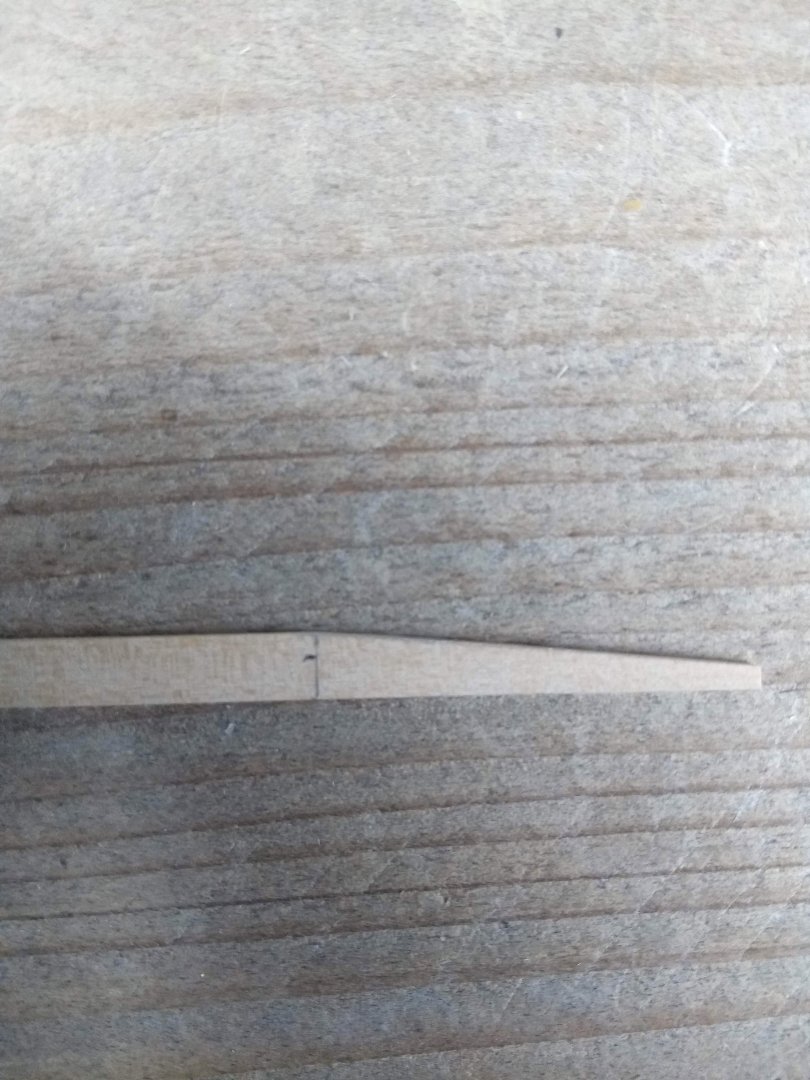
The seam between the pear and maple has turned out nice and sharp, which is a relief! After sanding it will look something like this:
I will now continue below the waterline and have decided to use 12 cm segments as above. It will be a long frustrating task to use whole length planks with that much curvature on each, so to not run sour of the task, I will use the shorter sections.
BR
TJM
- brunnels, KurtH, KARAVOKIRIS and 6 others
-
9
-
This looks like a fantastic kit, as always from Chris, and beautiful presentation!
The quality of Vanguard Models just keeps rising and rising 👏
- DB789, Oboship, Knocklouder and 4 others
-
7
-
-
Log entry 18 - changing plans slightly
Having tried a few times without achieving results I was happy with, I decided to change tactics.
The waterline kept becoming too wobbly so I decided to lay a full length plank along the waterline. This was fairly easy to do. I used small nails along the waterline to register the plank and formed it in place with a hot iron, keeping it in place with pins:
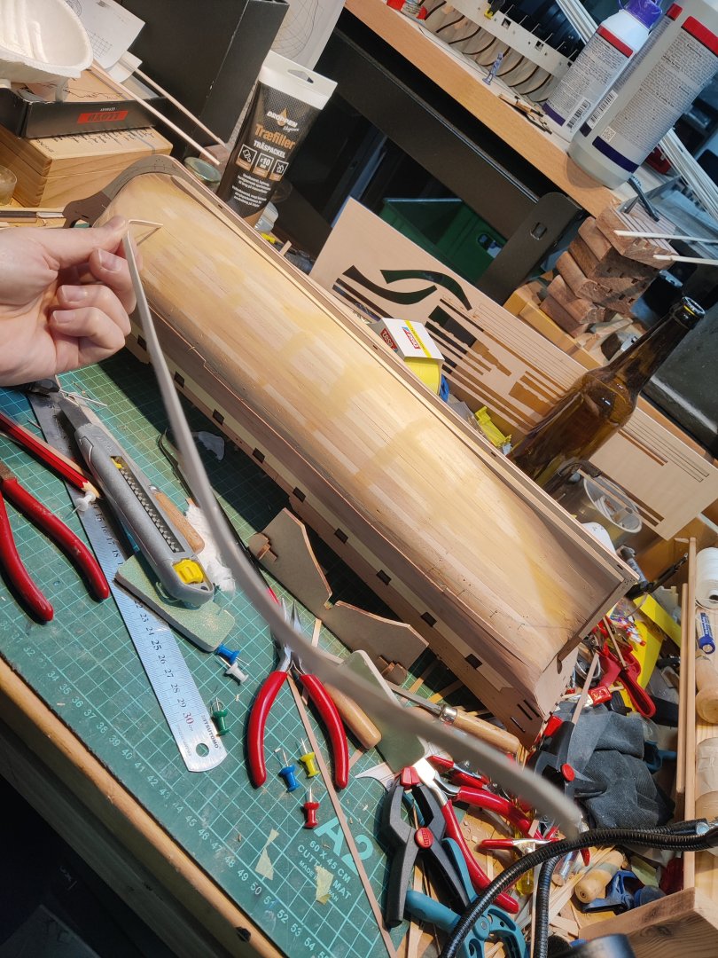
I did this on both sides and this looks much better in terms of straightness. I have then been adding a few more pear planks and this is how it looks now:


Now, this changes things quite a bit in terms of planking strategy below the waterline. Obviously, the planks will not follow a realistic planking pattern as originally intended. I will instead view it as an artistic representation of the white painted hull below the waterline where you would not see how the planks run anyway. But since they will be visible in this case (if I make a good enough job and don't paint over it in the end...), I need the planks to have a aesthetically nice run.
I think the best is to divide the hull in planks that run parallel to the waterline. I will just use the waterline marker to do this. That will result at quite thin planks at bow and stern, especially at the stern which will be a departure from a normal planked hull. I think it could work. But I have to decide whether to use full length planks or shorter sections like above the waterline. I feel it will now be better with full length planks for this aesthetic, but the planks have much more severe curves compared to a natural run and I am worried that I wont be able to get tight seams with full length planks!
I will now plank down to the waterline with pear on both sides and the try to make a decision on the lower part then...
If someone has any inputs or other ideas I'd be happy to hear them!
BR
TJM
- wvdhee, Thukydides, schooner and 8 others
-
11
-
Log entry 17 - two steps forward, on step back...
I have added another couple of plaks on both sides an am reaching the waterline.
So i took the plunge and made a first attempt.

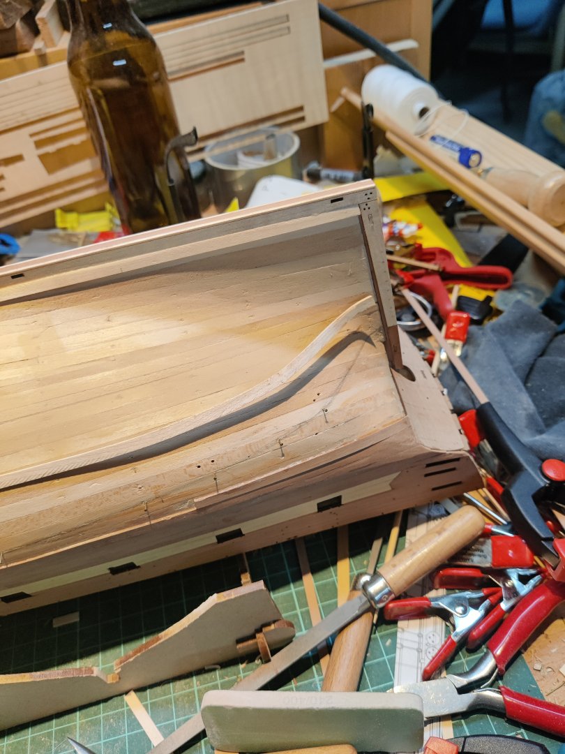
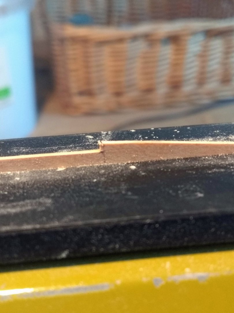
It seemed to work fine, but sighting down along the hull, the waterline between the pear and the maple looked a little high in the middle. So i re-drew the waterline on top and sure enough:

This looks to be 1 or 2 mm to high 😕. I only looked at this for a few minutes before deciding to rip it off and try again.
I marked the planks to remove and went ahead:
It came off easily enough with no damage to surroundings. I re drew the waterline:

It still looks like I will have to add maple to the middle plank, but that was what turned out wrong the first time. Hmm. Time to think and then try again.
I don't want to abandon the idea and paint the hull, as the wooden hull is one of the main appeals to me. I could also run a plank along the waterline and have a simple, non authentic run below the waterline, also using full plank lengths instead of the 12 cm lengths. I think that could look fine and be an aesthetic choice, but it would feel a bit like cheating with the planking! It would be much easier though.
I will at least try again with the realistic run of the planks before giving up and trying the other option.
BR
TJM
- Ronald-V, Beckmann, Thukydides and 2 others
-
5
-
You are very welcome! And you are right, I completely forgot to mention that ships of the same construction is also shown - that sometimes adds a lot of relevant drawings to a subject!
I just dont understand why, when they went to all of the trouble scanning thousands of drawings and the old analog indexes, they did not make a simple database with a tiny bit of metadata. It would have taken so little effort compared to the work already done to make a searchable database. Instead we have a digital copy of the analog archive, including the analog indexes. And then the system is just not very friendly for browsing! It takes alot of mouse clicks to go through the files!
But the index does make all the difference when looking for specific ships.
Another 'tool' is this site:
https://trap.lex.dk/.taxonomy/4677
It lists many of the ships by class and includes a few low res images of drawings and models of interest. It is a bit inconsistent in the quality of the data, but it is a good way to find interesting ships and then go to the actual archive linked above to find the information 'first hand'.
-
19 hours ago, Beckmann said:
Hi TJM,
I just came across your build log of the Frigate Christiania and this topic about the CAD-plans on the basis of the riksarchiv.
I am myself very interested in the danish navy and have a build log myself about building the stern-section of the orlogskib TRE KRONER from 1742.
Maybe we can get in contact about how to use the riksarchiv best, I have the problem of not understanding danish language very well, but my method of working with the plans is similar to your method.
Matthias
Hi Matthias,
I have been following your Tre Kroner build from the start with great interest. It is really fantastic work you are doing! It was partly your work on that that got me inspired to try these adaptions of plans myself - I even started with a stern section like your build! (I have just not allowed myself to progress beyond the design and test cut stage for fear of having too many active projects).
I am more than happy to discuss how to best use the Danish National Archive (Rigsarkivet), though I am not sure I have the best way!
It took me a while to figure out how things are organized. It can seem like a jumbled mess!
There is an index by ship name accessible here:
https://arkivalieronline.rigsarkivet.dk/da/billedviser?epid=17172954#190667,31951582
The entry for Tre Kroner, as an example, looks like this:

The interesting part here is the section 'Tegninger hørende til skibet' (drawings belonging to the ship), as it lists the know drawings of the ship from the differen portfolios, A, B, C, D and G. The digital archives for A especially is incomplete and some of the references are not available online. This is also to some extend true for B, C and D.
However, I think the missing ones are then available in one of the other portfolios, most likely G, but there are no traceability between these! For instance, A666 is not available. It likely contained either the ornamental drawing or the profile and bulkhead drawing (because it is underlined as the main file). However, these both appear in other files.
The actual drawings are available here:
https://arkivalieronline.rigsarkivet.dk/da/billedviser?epid=17149179#189566,31913766
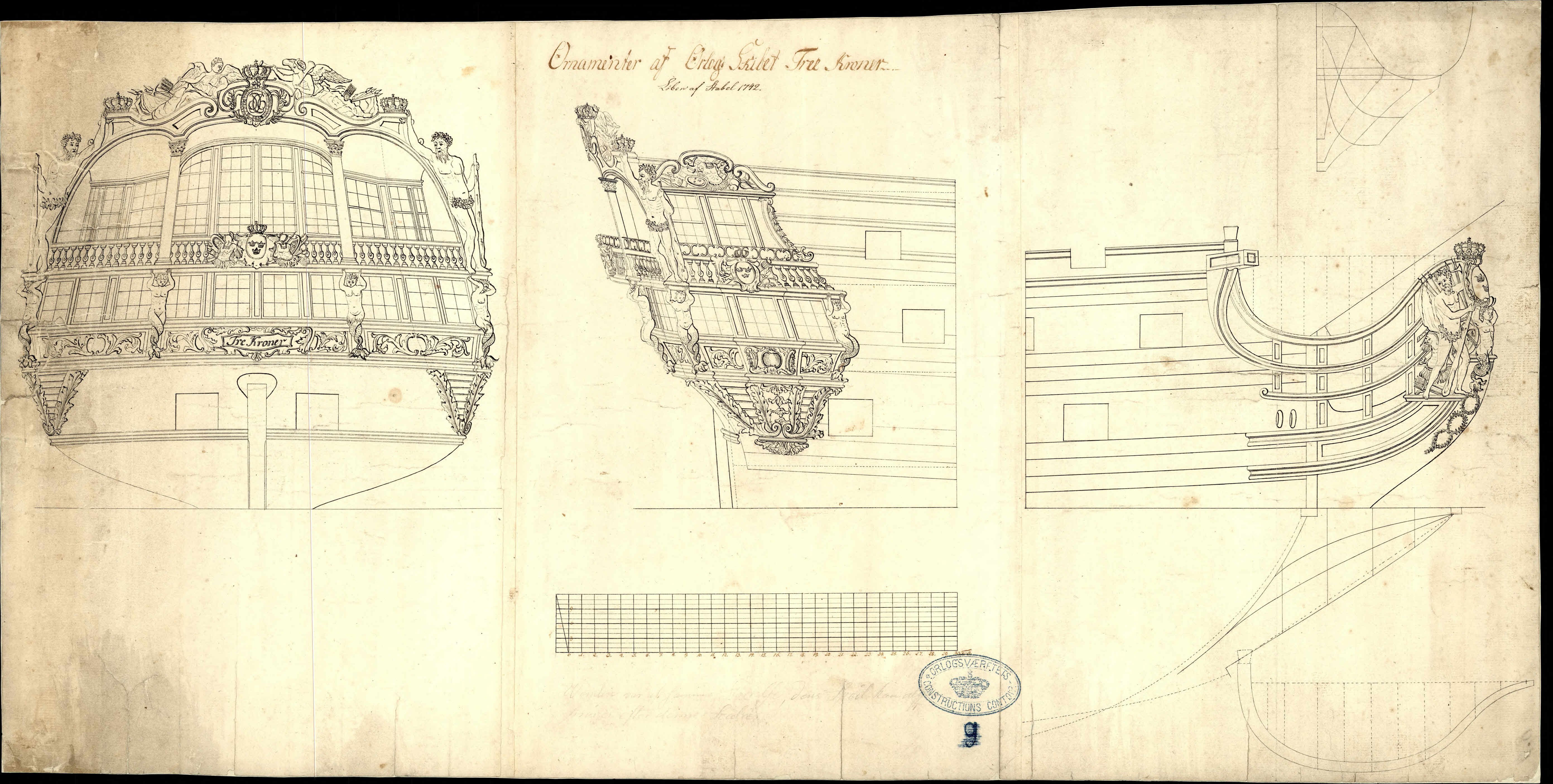
And for Tre Kroner, I find these:


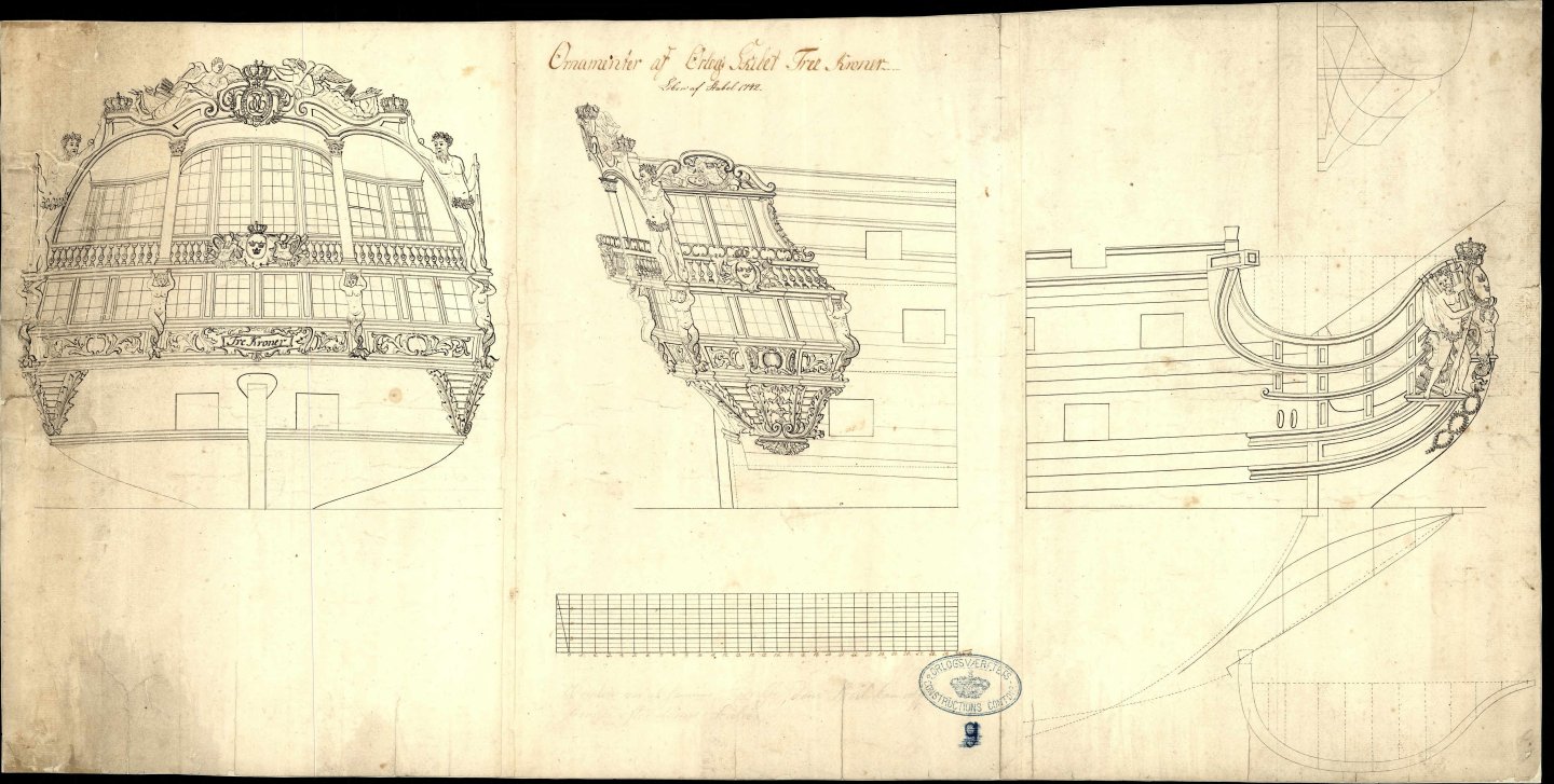
These are A768, A1200 a-e and G2853.
The others are not available online, but this is where I suspect the they may refer to one of the other files that are available! But I can't be sure of it.
Note that there are two distinct copies of the ornaments - that is actually often the case! Usually, one will carry the handwritten approval by the sitting monarch, in this case the first one, A768.
This is how I navigate the archive! If you have any need for help translating something from Danish, I am more than happy to help! Just send me a PM. I am just limited by my lack of knowledge of marine terminology in both Danish and English, so I run into words that I don't know the meaning of in Danish either, even though i am a native! But I'll do my best! 😁
-
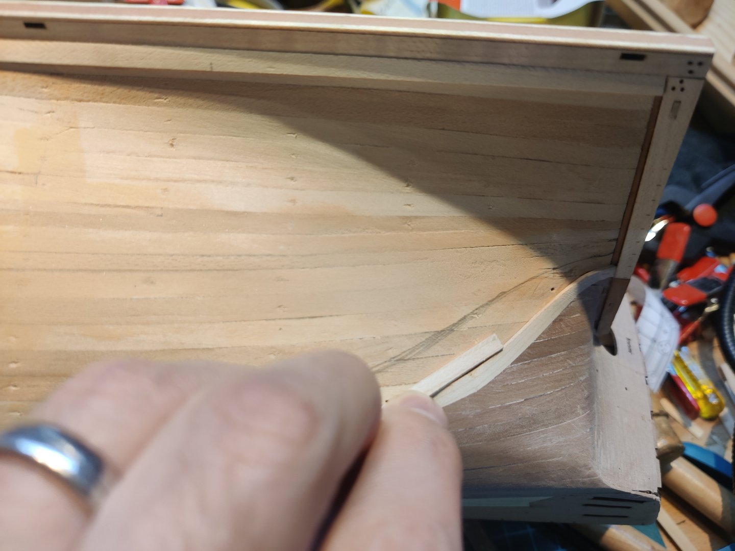
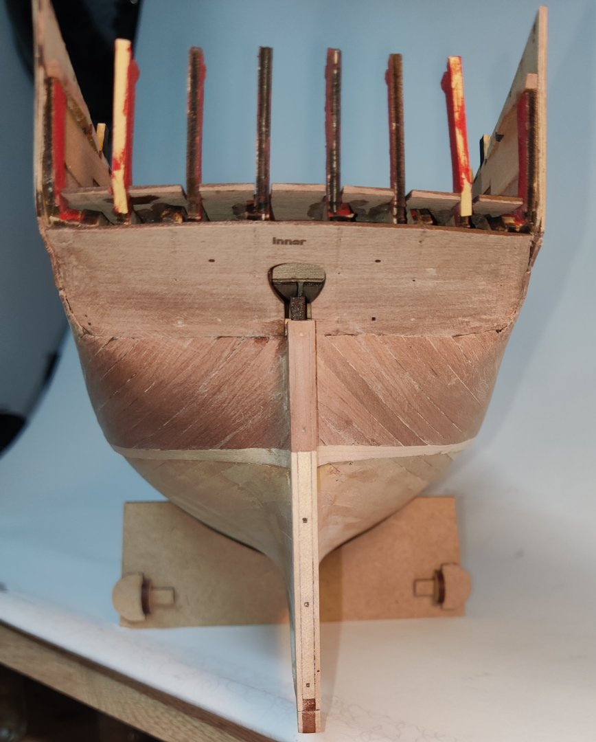
Log entry 16 - an few more planks and the garboards
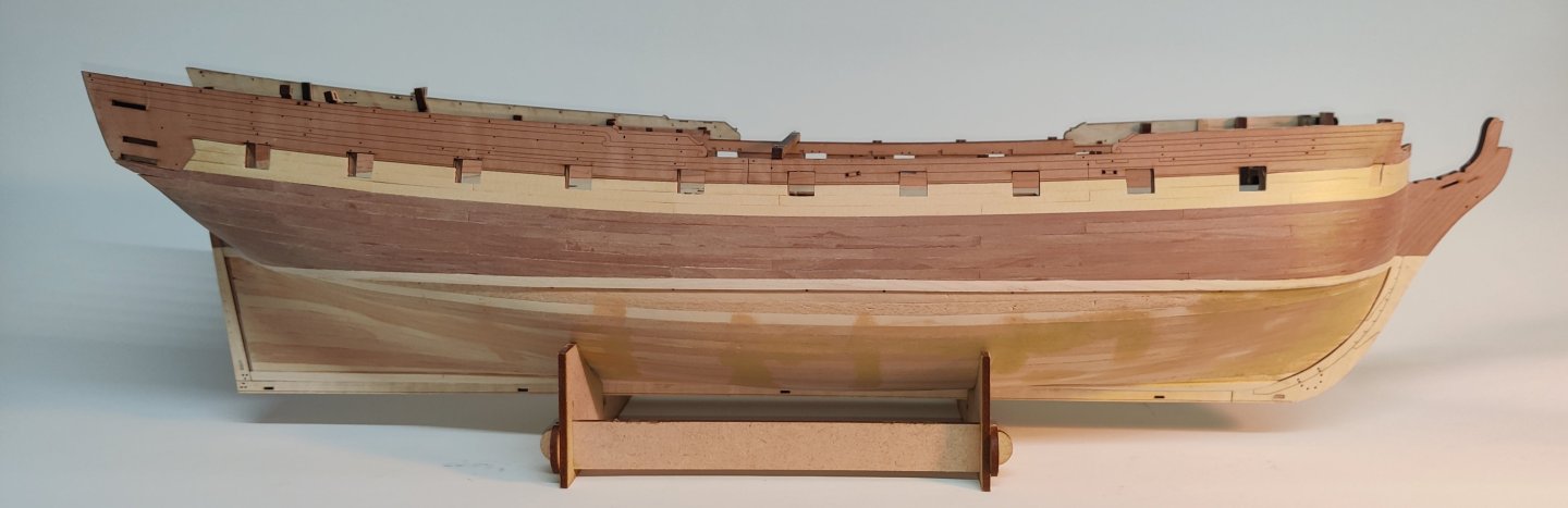
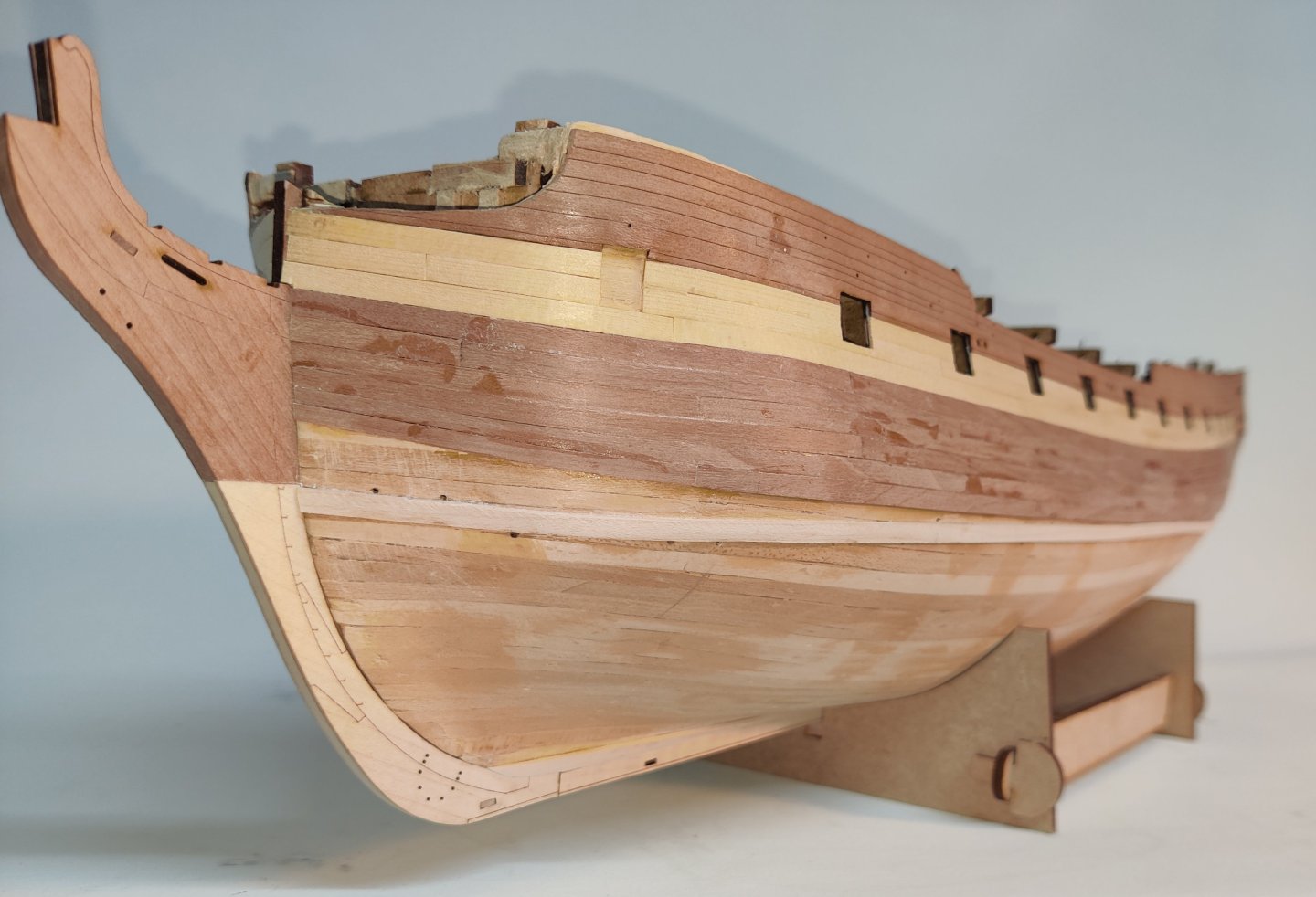
A few more planks have been added. The pear below the yellow cedar now shows where the wales will run.

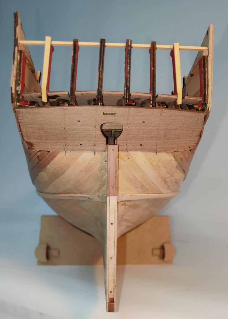
I now soon have to measure up the hull to plan the tapering of the planks at the bow and have therefore added the garboard planks:
This went well enough and I should be able to measure up the hull now or after one or two more planks.
BR
TJM
-
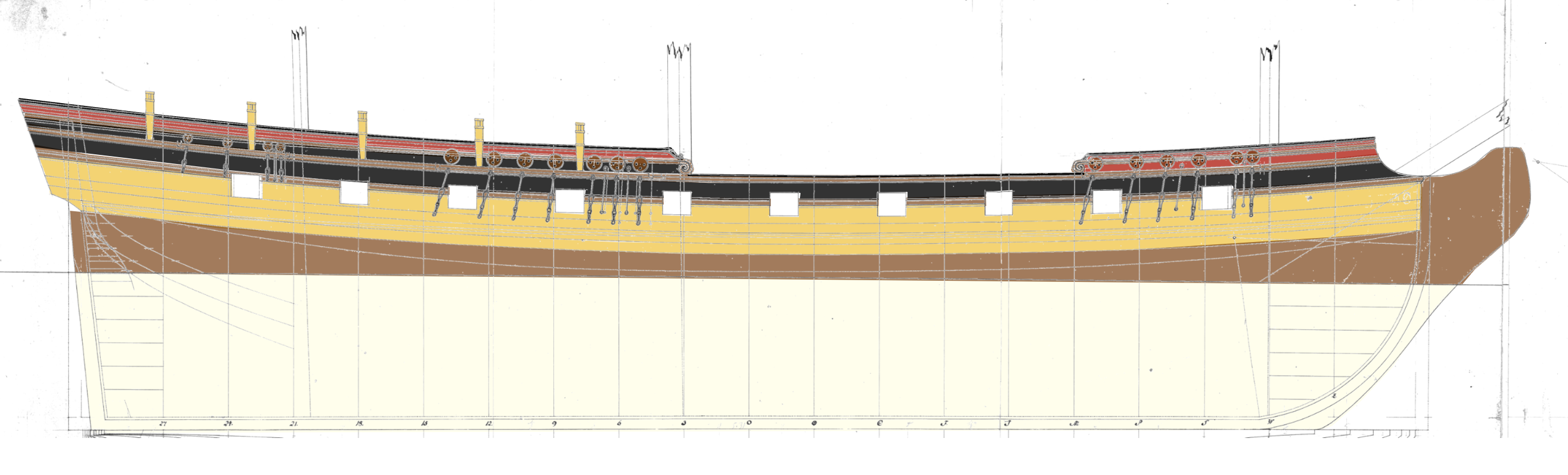
Falster, 1810 - a gun brig with 18 pounders
I have been eyeing one of the latest releases from Vanguard Models, the gun brig Adder, and the upcoming Harpy with interest. I like the older ships for their graceful curves, but I am impressed with the huge firepower these later brigs and sloops were carrying!
When the British ran off with the entire Danish fleet in 1807, they got also 6 smaller gun brigs carrying 18 pound carronades. These were replaced by a new generation of gun brigs which carried 8 x 8 pounder long guns and 8 x 8 pounder short guns, not quite carronades, but of similar size for their poundage.
This is something in between the aforementioned Adder and Harpy in terms of firepower, but with more long guns in the mix.
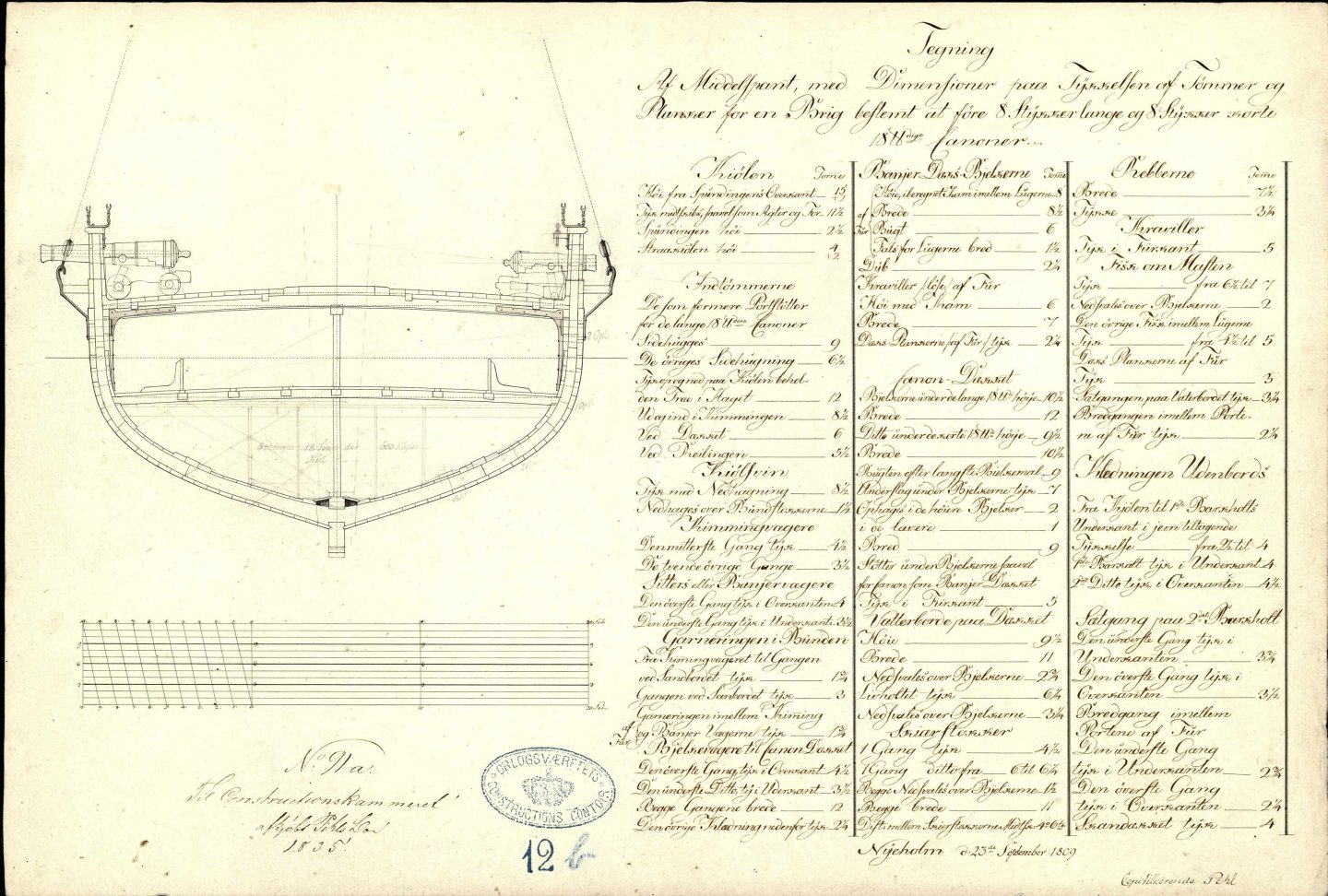
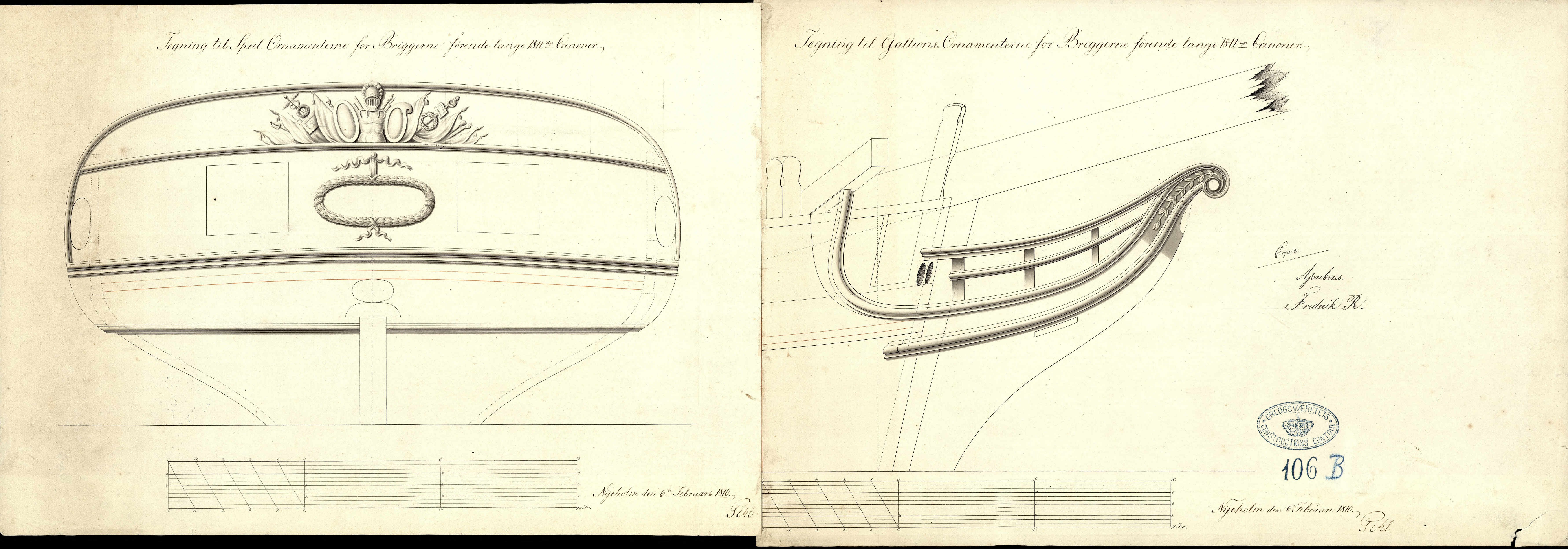
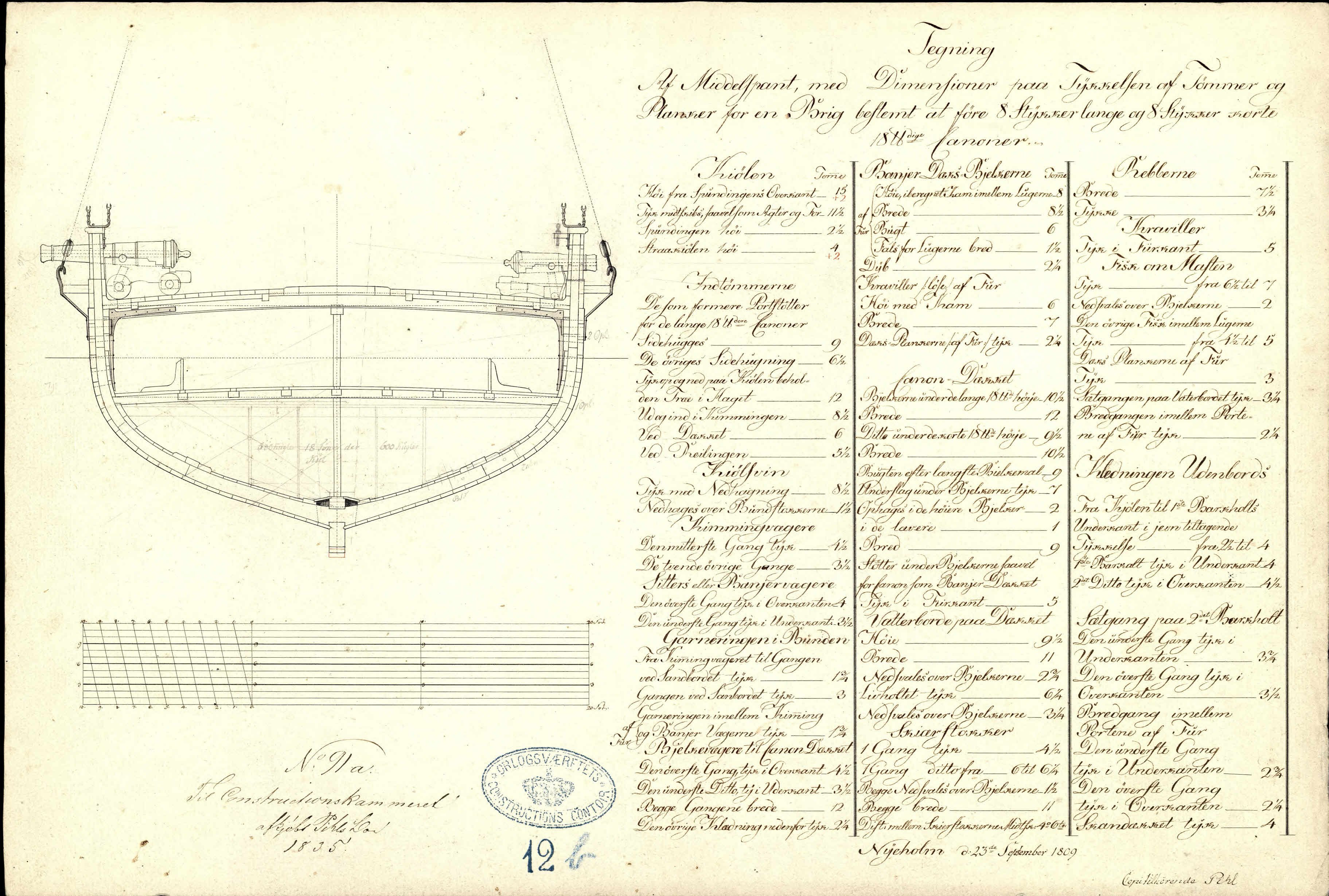
Here's a few of the very many available original drawings:
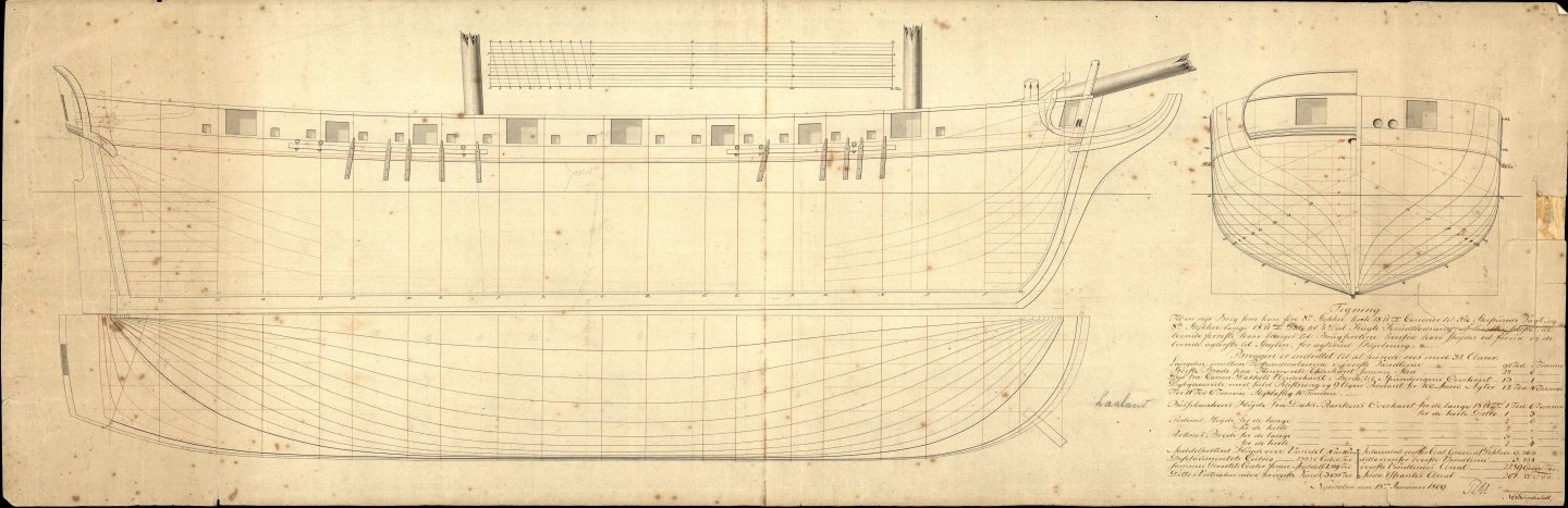

And here's one showing both the long and the short 18 pounders (actually almost 20 british pounds, as 1 Danish pound was around 1.09 British pounds):
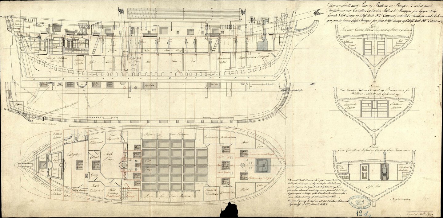
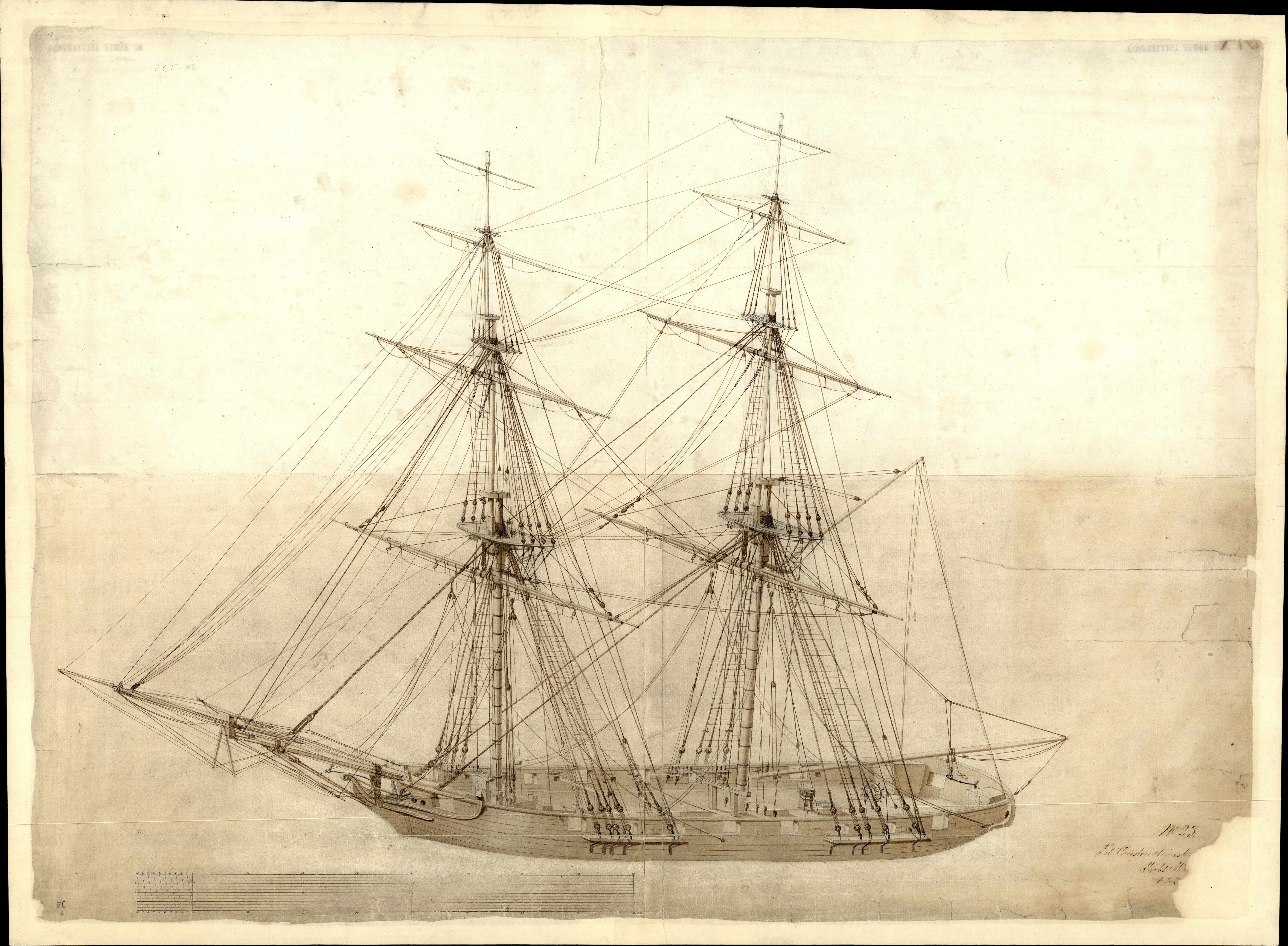
And then something a bit unique, at least I have not found other drawings like this one yet in the archive:
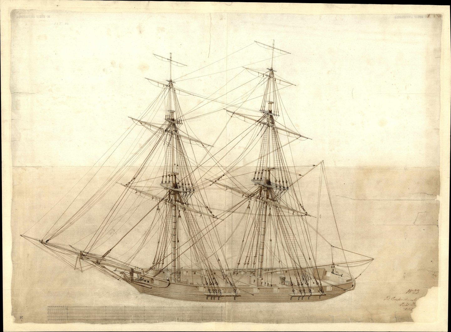
This is basically a perspective drawing showing the rigging and deck fittings in great detail.
From the PoV of adapting the plans to a PoF model, this is quite simple compared to some of the previous exercises. The plans from this late period are very easy to read and there are plenty of drawings to go with.
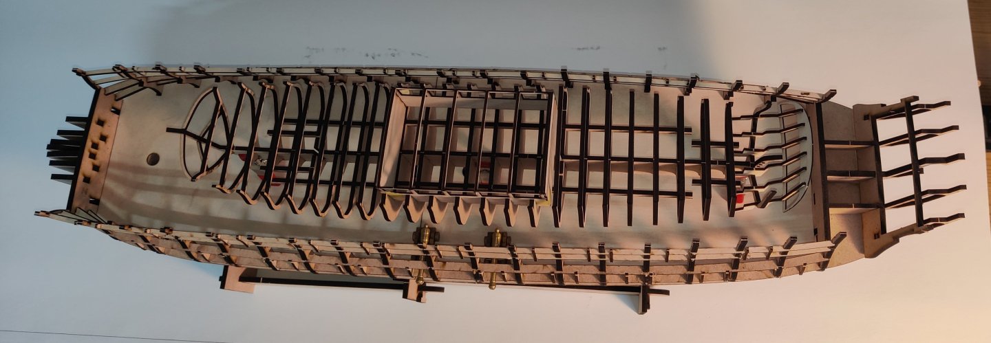
I have only done the very basics for now, keel, bulkheads, braces and a little at the stern. And the the upper bulwark patterns:


I was very surprised at the size! I should have used 4 mm mdf, not 3 mm! I of course knew how large it was by it's numbers, but it is something else to see it in real life. This is why I think these exercises are so fun! (it is a very good way of procrastinating....).
It is also not very pretty, in my opinion! With it's very flat front and generally boxy shape and the slightly disordered gun port sizes due to the mixed gun types. But it does have some character!
As mentioned, it is very large for a brig, I think. Here is a few comparison shots with my current Sphinx build (with modifications):
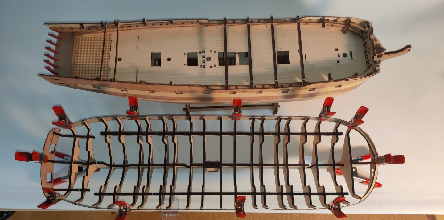
It is close to as long and the deck is a good deal wider. Quite 'chunky'.
Continuing with this, I would have to redo the prow parts, as the fit is not great, and modify the run of the bulwark patterns at the bow as well. I also made a mistake on the deck level on bulwark 15 and I would need the stern piece to be of ply to be able to bend it without cracking it. All of these were very good learnings and I feel that I am beginning to know what works and what doesn't, at least in these very early critical stages of the construction.
Thanks for following along on this journey!
BR
TJM
- mtaylor, iMustBeCrazy, Gregory and 4 others
-
7
-
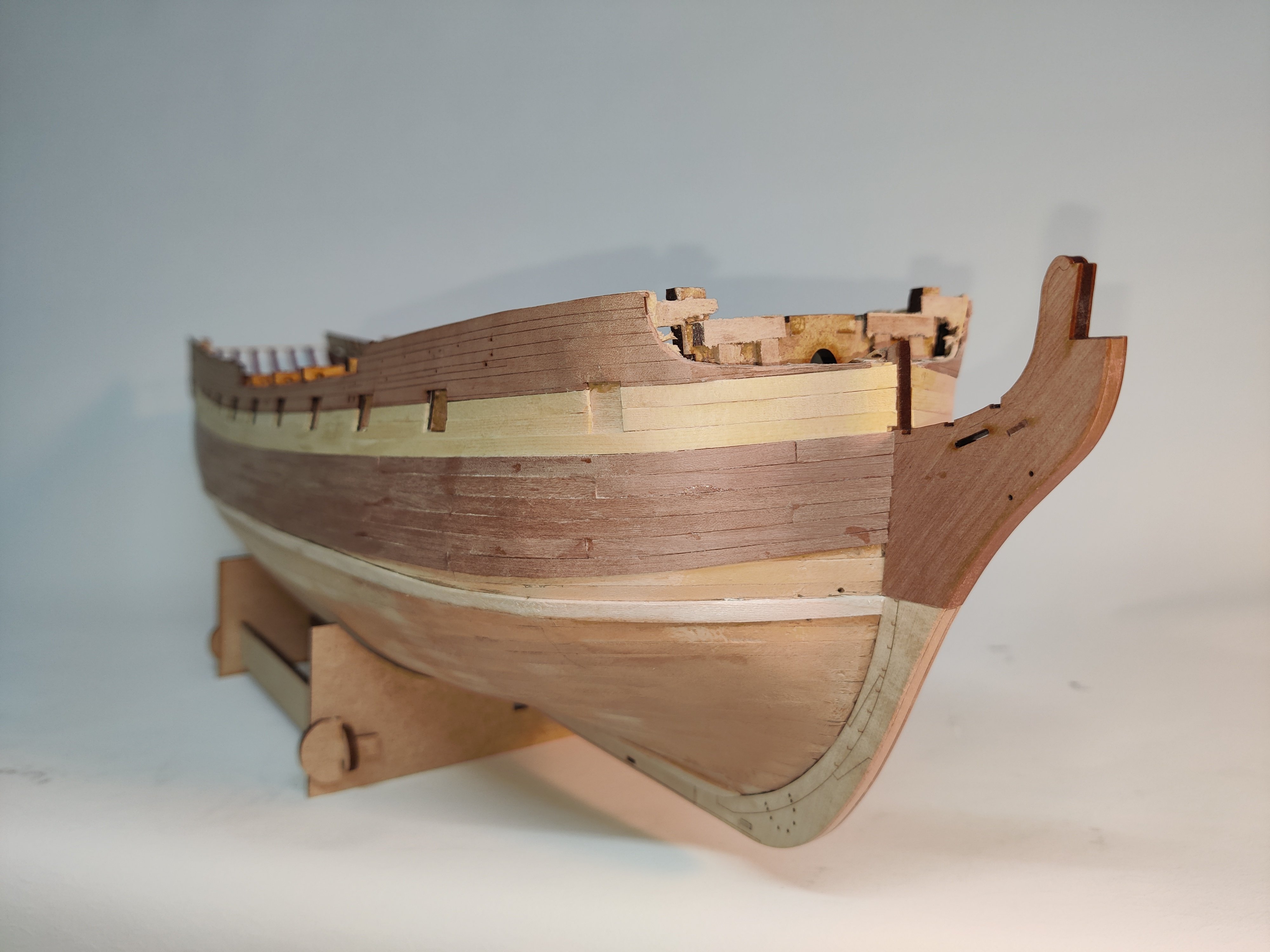
Log entry 15 - catching up on planking and prow modification
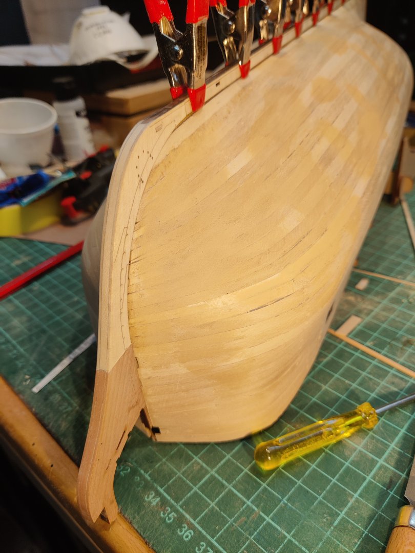
It has been a little while since my last update due to many things, but mainly I have been waiting to receive a waterline marker (I caved in and bought the Amati one - it is not as stable as I would have liked, but it can be made to work...) and then I have been putting off making the modification to the top of the prow - the cut-away around the bowsprit (does that have a proper name?). It was a bit scary to start taking a Dremmel to the prow! But I thought that if anythings went wrong, it would likely be salvageable - at least more so than later! So here goes:
Here is the starboard side planked to the same degree as the port:
I'm liking the look! Will be good to get a few more planks on to really show how it will be. Notice the prow cut-away and the waterline marked.
And here's a few closeups of the prow:

It looks a little rough and it will for a long time. I probably wont cover it up until I add the forecastle deck. I will just hut out suitable planks of pear and decking (likely maple) and cover the frame here. Then I can add sone details like a ladder to the forecastle and a railing on the top that fits with the forecastle bulwark.
Now the planking starts in earnest and there are only 3-4 pear planks until the big challenge that will be to get a nice, even waterline between pear and maple!
BR
TJM
- KurtH, KARAVOKIRIS, Ronald-V and 8 others
-
11
-
8 hours ago, Doreltomin said:
Thank you very much for showing us this lovely yacht! As I have mused through the plans there are some interesting details on it, for instance the deck which curves down to the stem to allow for the cables of the anchor to come up smoothly. A little yacht worth of being considered for a nice model, which at 1:64 would be of just the right size. I also completely agree with you that dividing modeller's attention to several subjects at the same time is a good way to never finish anything. However, I know modellers which work just like that, taking small steps to several models in the same time. Also unlike the girlfriend, a ship model is never jealous of being left some time on the shelf for another ship model! 😉
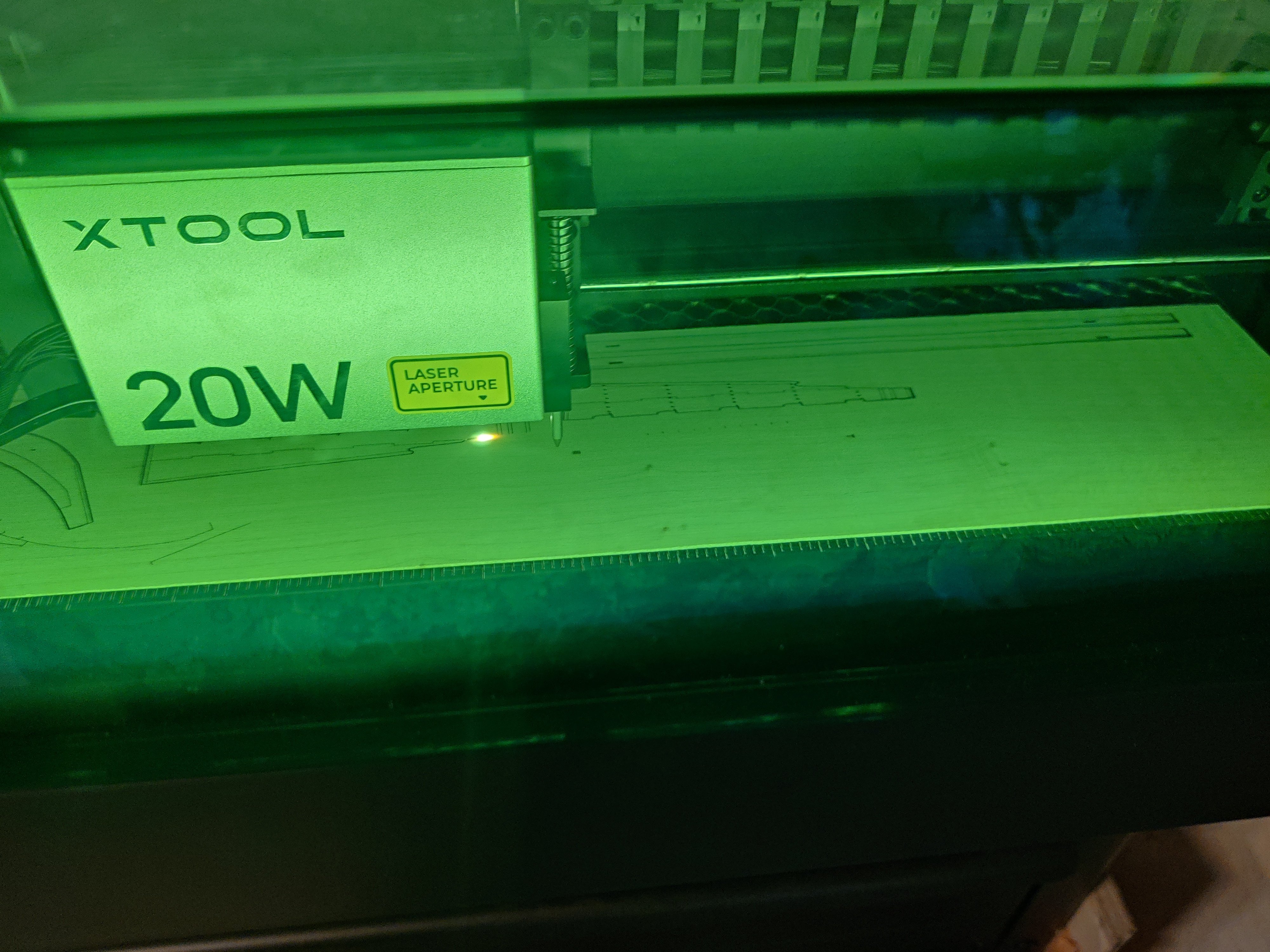
Also you did a very nice job in cutting these pieces and putting them together. It seems it takes much less time to project the cut on a computer and then laser it all in a single pass than it would have to cut them by handsaw and then smooth them one by one! Nice one!
Thank you for the very nice comment! Indeed, many fun features, I had also noticed the dropping deck.
Indeed, it does not take too long to do this, at least not the small ships like this one and only the base structure. I think this one took around 10 hours to do in CAD, another couple to lay it out for cutting and one to cut it on the laser. I am sure it would have taken ne forever by hand and scroll saw!
- Doreltomin and mtaylor
-
2
-
7 hours ago, druxey said:
That is a lovely and unusual subject! I vote you continue.
Thank you Druxey, I will definitely consider it. But I am not allowing myself more than one truly active build at any one time, or I would never finish any! So It will be a long while no matter what before I continue, with this, Bornholm, Fehmern or another of these practice projects.
- davec, Doreltomin and mtaylor
-
3
-
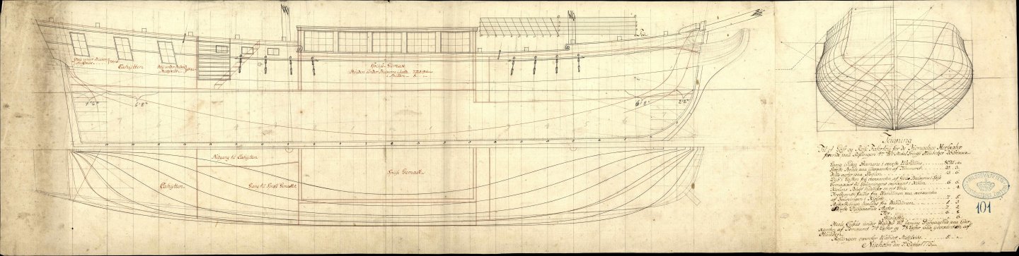
Ørnen, Royal Yacht of Christian VII
I have been away from home and with no workshop, and have therefore been adapting some more historical plans.
This time I am looking at a small Royal Yacht called 'Ørnen' (the Eagle).
It is a curious little vessel entirely geared towards ensuring the comfort of the monarch. It is basically a large suite with two bedrooms (labelled king's and queen's, respectively) and a living room. Midships there is a finely decorated dining hall and at the bow a kitchen with two stoves.
Armament consists og 26 4 pound 'houbitzers' that seems to be essentially small swivel mounted carronades. Good for defence!
Here are a few of the many original drawings:
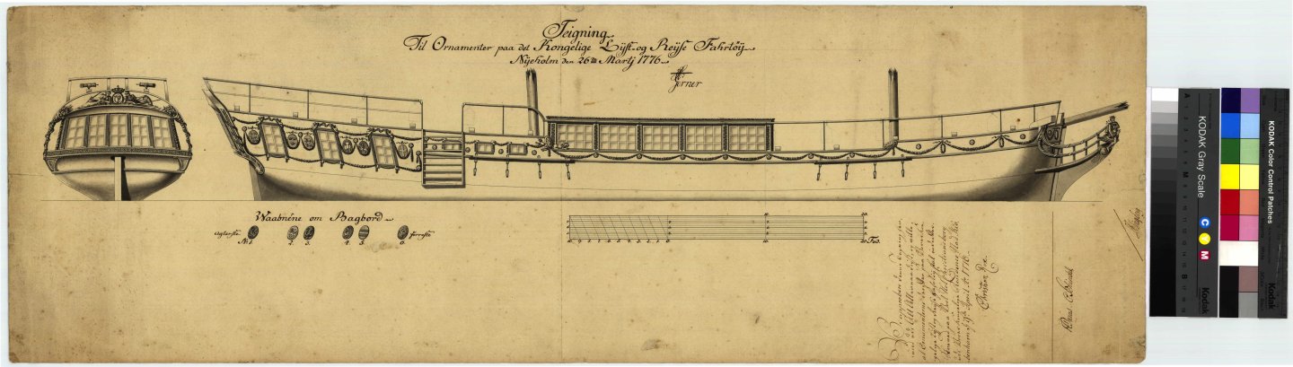
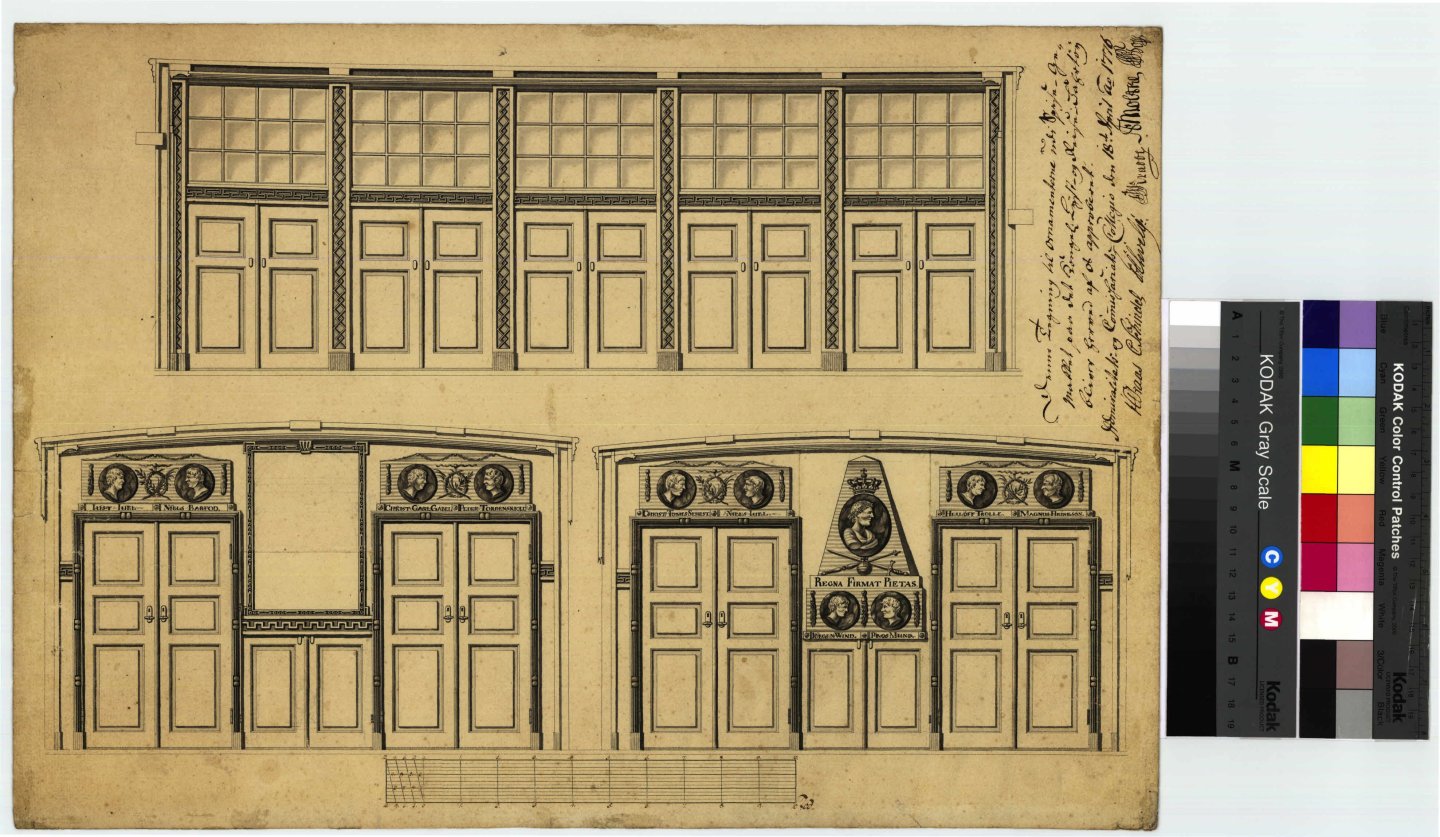


The dining hall is an interesting feature to model, and in general it would be fun to model the interior of the ship to a reasonably high level.
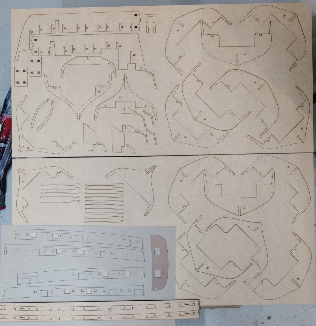
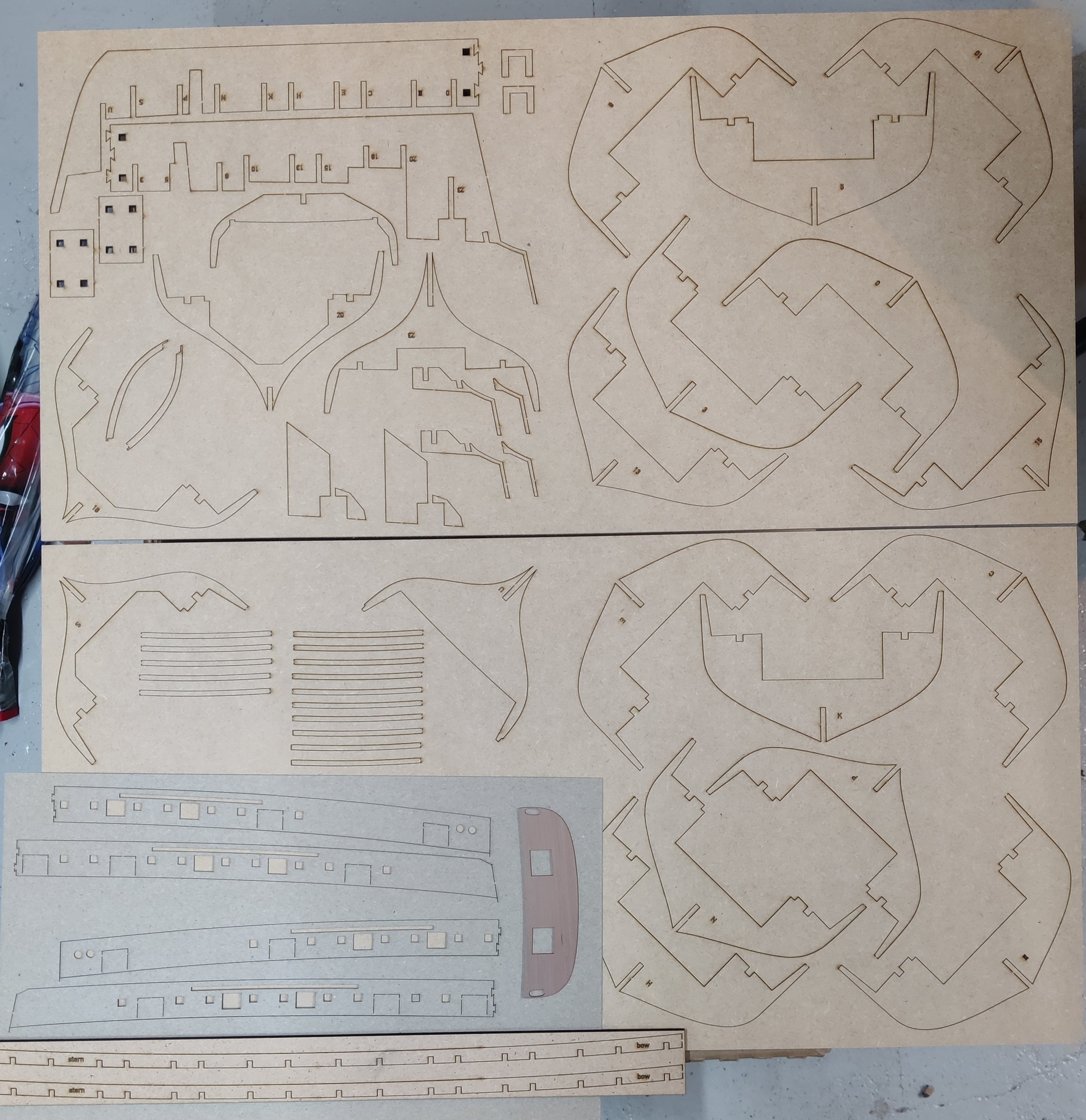
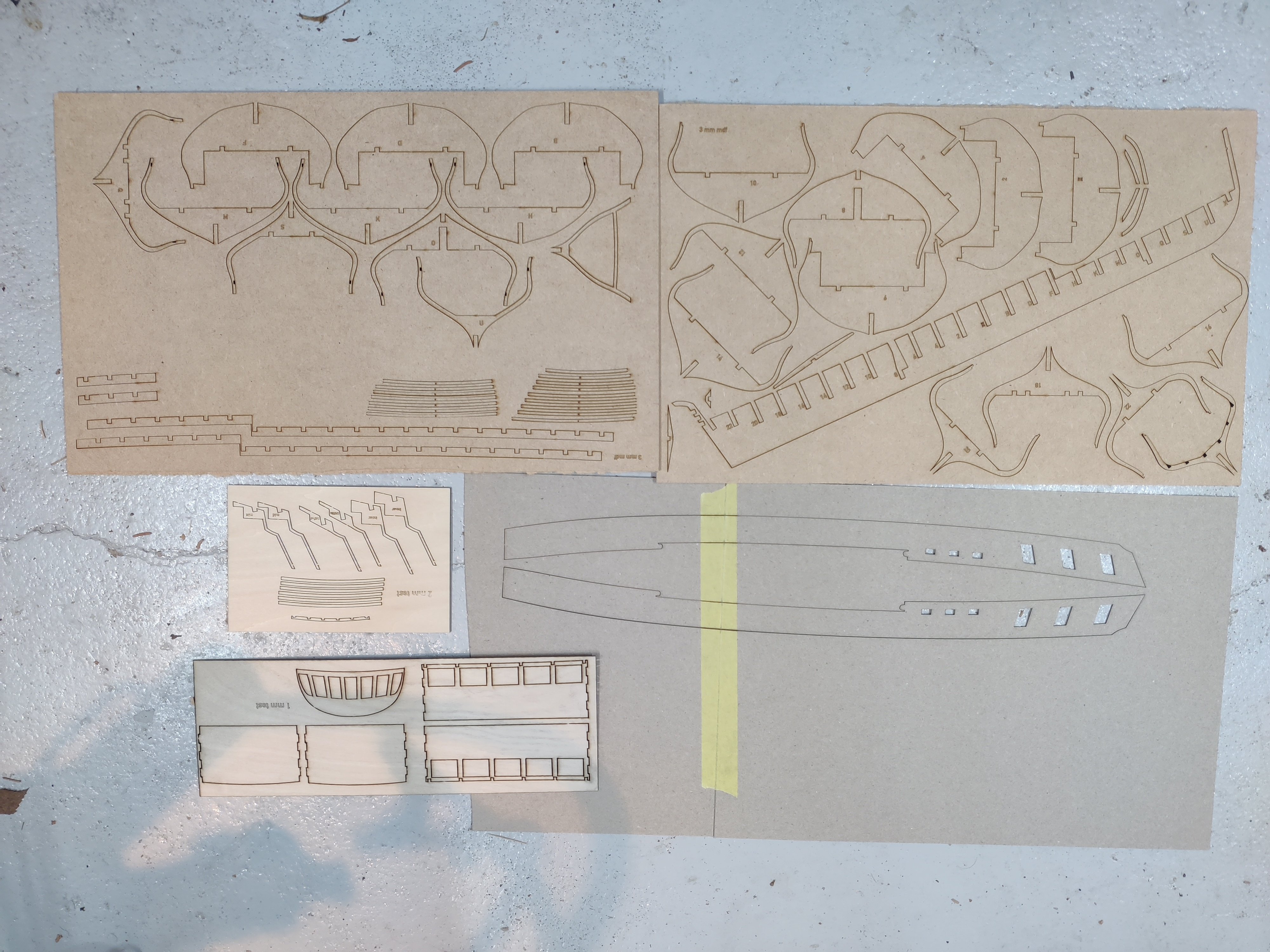
Here are the lase cut sheets I made:
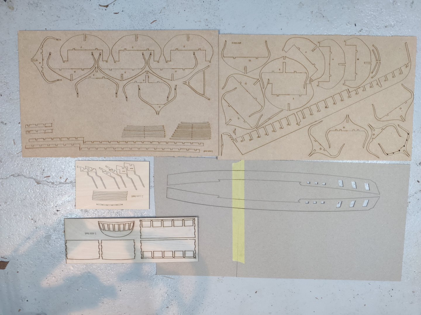
Mostly 3 mm MDF and then a little 2 mm and 1 mm ply. Most of these thinner pieces I would do in pear if I was to continue with this model (I would like to, but that will be in the distant future, if ever...), but the ply is fine for checking if it works.
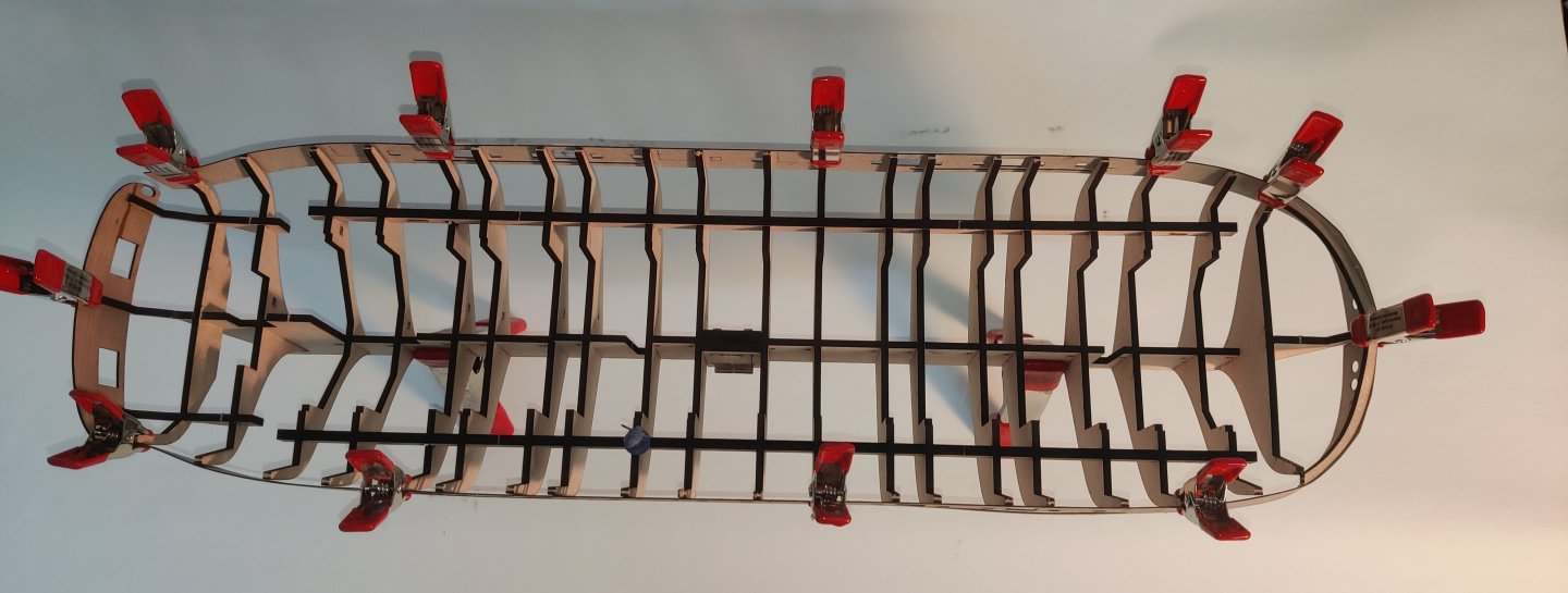
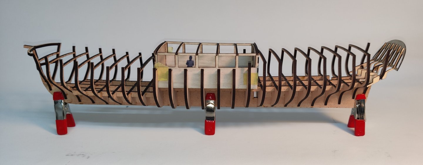
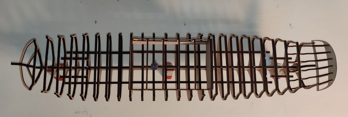
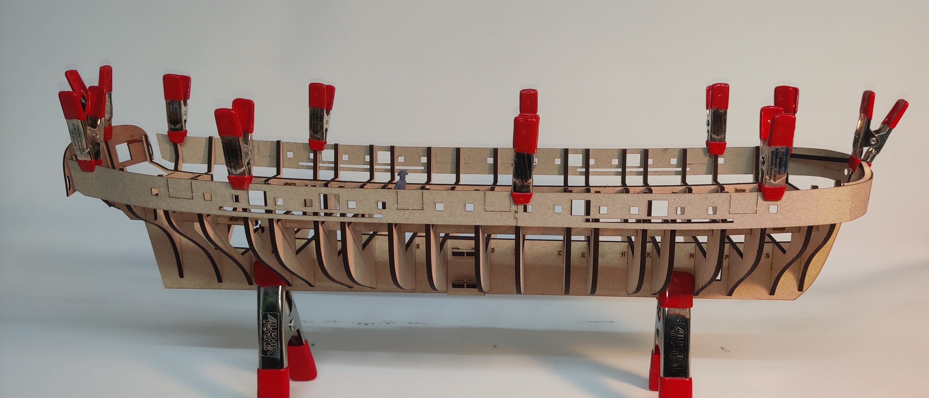
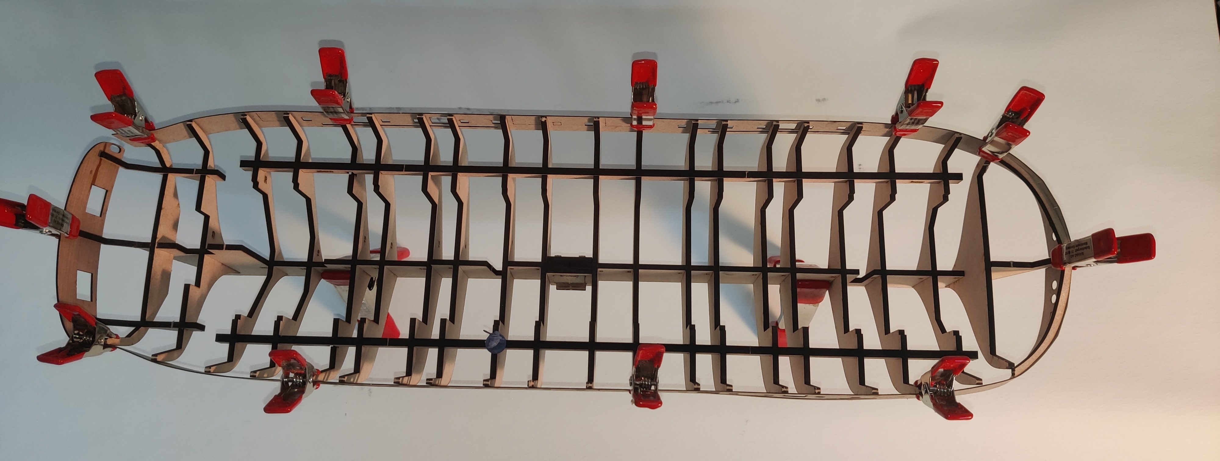
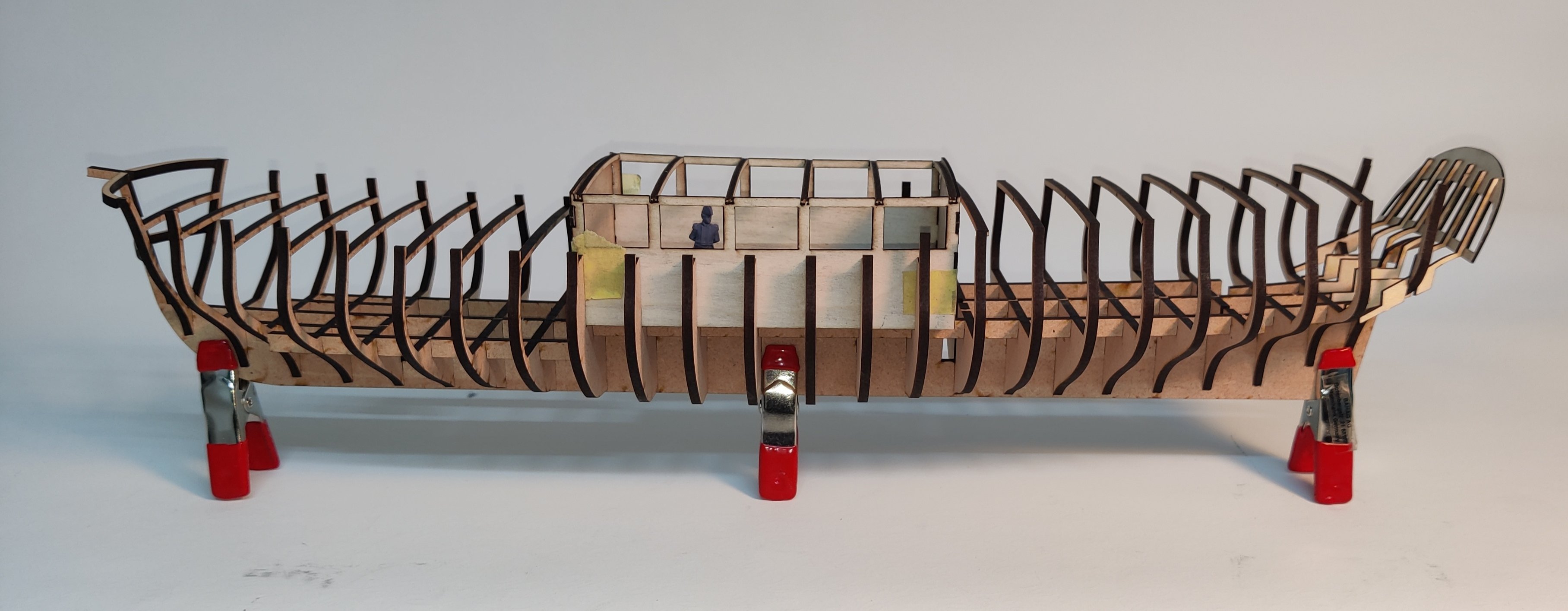
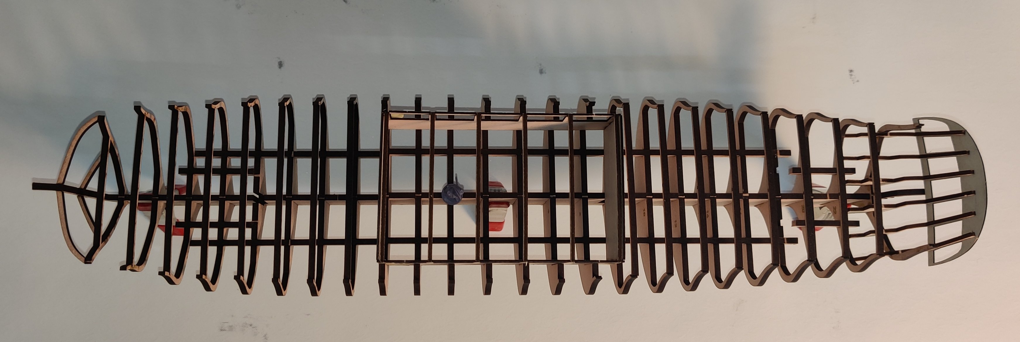
And here are a some photos of the puzzle fitted together (very little glue for now, just at the stern and bow):
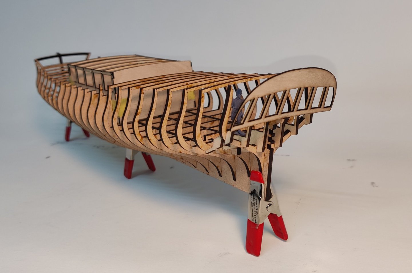


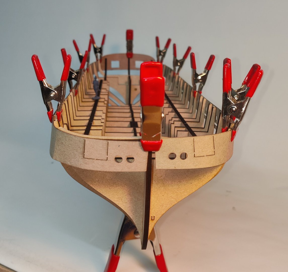
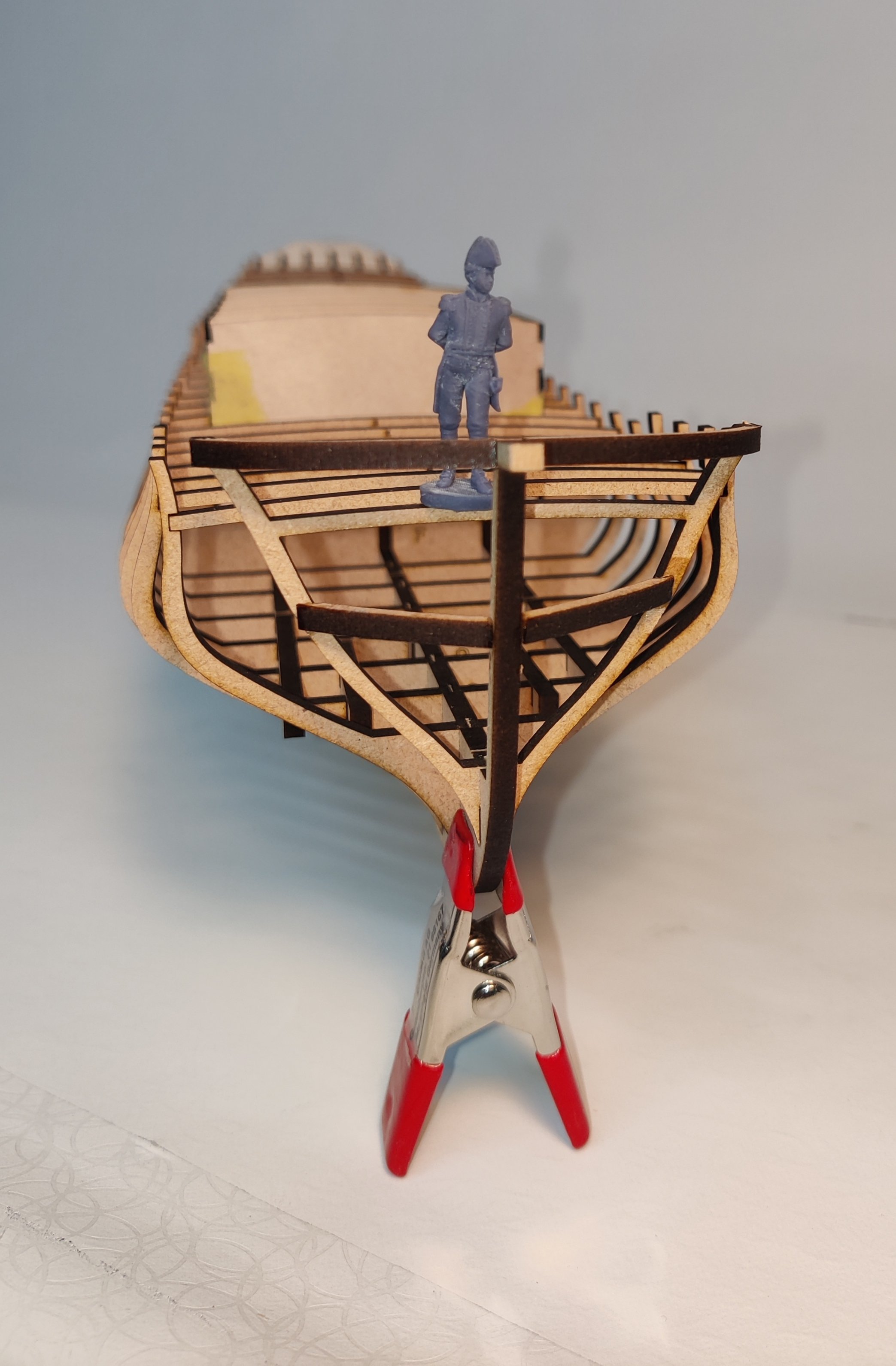
And a few with the test cardboard bulwark patterns:
It is a small ship, 45 cm at 1:64.
Here it is on top of Bornholm from the last post:

I am a bit torn on whether I like the ship due to it's curiosities or if I think it is a little ugly with that dining room protruding in the middle. But it has nice enough hull lines, and is a bit of an unicum.
But now that I am back home, having spent an evening cutting this, I will get back to planking of Christiania 😁.
BR
TJM
-
11 hours ago, SJSoane said:
Thanks so much, Yves, Scrubby and Mike, for your kind comments.
I have not posted in a while, because I was having to work out a few new challenges as I begin to work my way up from the lower finishing.
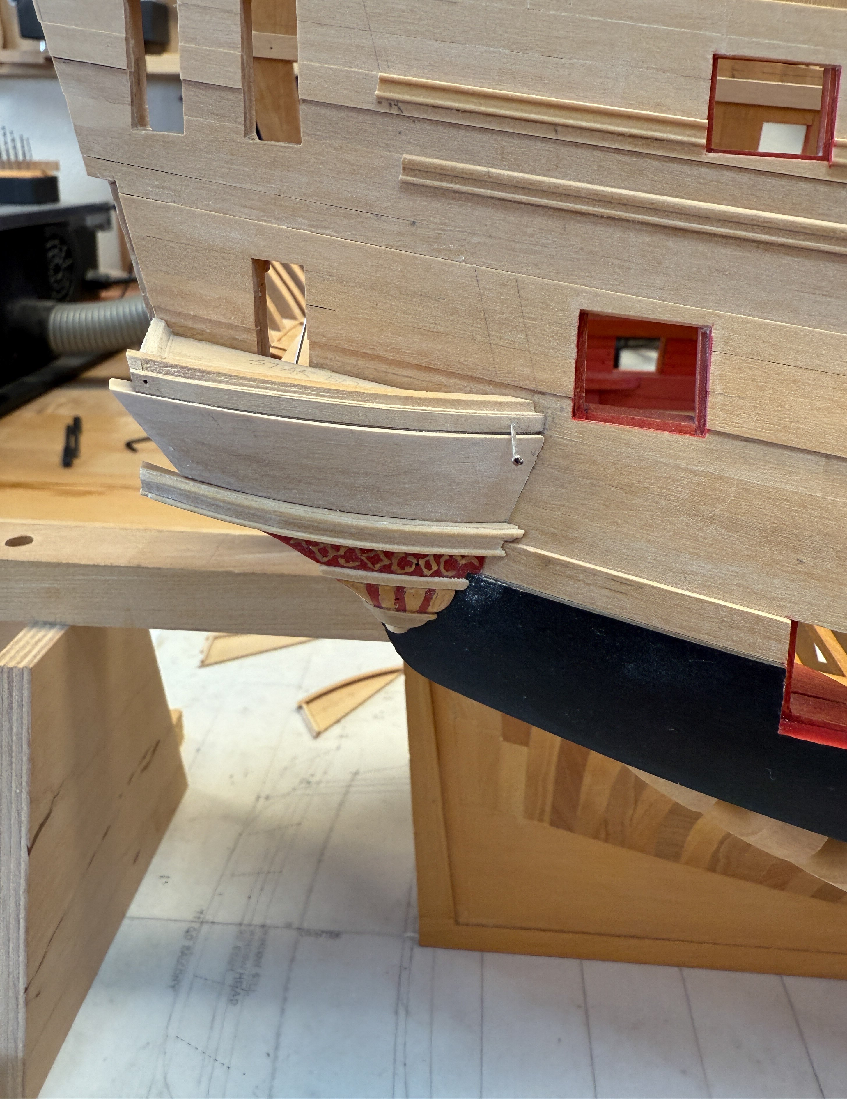
First challenge: how to frame and plank the quarter gallery surface above the lower finishing? This is the blue band between the lower stool rail and the lower gallery rim, below:
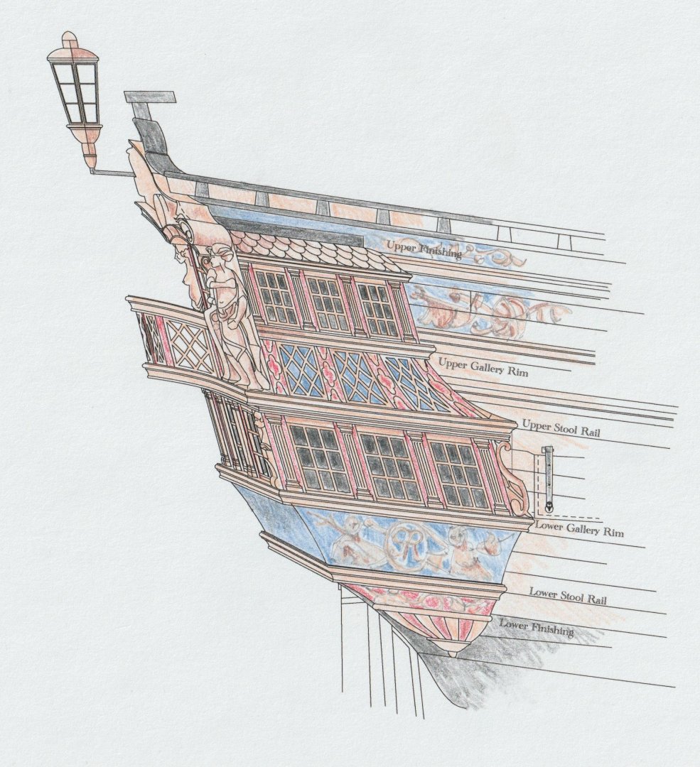
It curves, twists, and fays to the side of the hull with a shape I could not determine in advance. Also, how would I plank the inner surface once the framing was in place? I remember seeing a model of the Superb, with its stern in pieces. With the quarter gallery lying on its side, it is possible to see that this piece appeared to be cut out of a single block. So I decided to do that. This way, I could fair each edge to a known surface, and thereby discover the actual form. Then I could scribe the planking on the outer surface later.
First, I drew the top and bottom profiles as best I could determine from my drawings. I pasted one on top and bottom of a blank, then shaped the outer surface to match each edge. After refining while checking against the actual model, I came up with the shape and how it fit against the hull:

Here you can see the wicked twist in the shape.
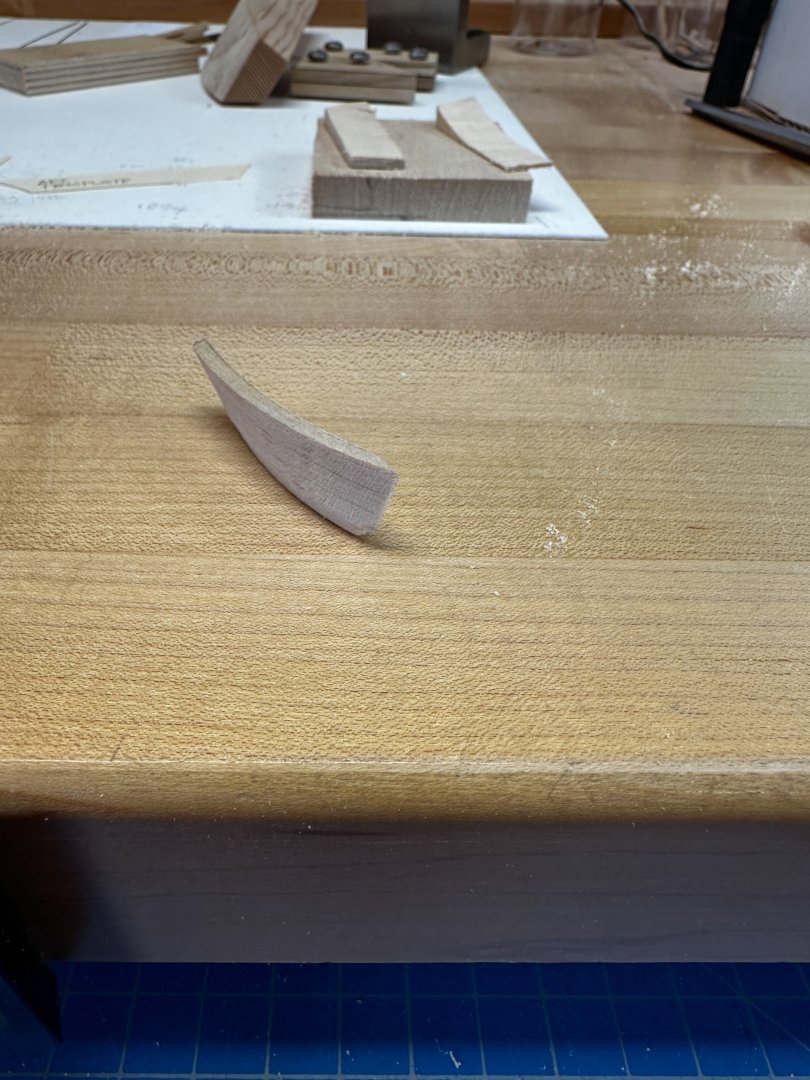
And here you can see it pinned temporarily in place (this is a trial blank I made out of basswood, to quickly see if this would work):

Next, I had to work out the shapes of the mouldings on its lower edge, which is the knuckle between the lower and upper counters. It took a long time to realize that the moulding here is the not the same profile along the counter as it is along the side of the quarter gallery. These have to miter cleanly at the corner, but they are very different profiles.
Looking carefully at the sections below (cut through the quarter gallery on the left, and through the knuckle of the lower and upper counters on the right), you can see that the face of the quarter gallery is almost vertical, whereas the face of the upper counter slopes back quite substantially. I finally realized that in order for these to miter together, the important thing is the thickness of the moulding in both locations has to be the same at the top and the bottom.
Also, the top edge of the moulding on the quarter gallery has to align with the roundup of the moulding along the counter, whereas the top edge of the moulding on the counter has to align with the sheer of the external hull planking.
A little geometry worked out the profile for each, so they would fair to their own surfaces while mitering cleanly at the corner.
Next challenge: how to cut the profiles with a scraper? All of my earlier mouldings were just straight blanks cut on a flat surface and later gently bent to the sheer of the hull. But these mouldings are on sharply curved surfaces. I decided for reasons of accuracy in the overall construction to shape the blanks of the mouldings to their final curves, rather than making flat mouldings and bending them to the shape later. I saw too many places for things to get out of alignment if I did not make accurate blanks to start with.
So how to scrape a shape on a curved blank, which also has top and bottom edges not at right angles to the face of the moulding? I decided to make formers, to which I could temporarily glue the blank, and use the former to guide a fence on my cutter holder.
Here you can see the cutter for the moulding on the quarter gallery. The face of the fence is at an angle to the cutter, corresponding to the angle of the top of the moulding. You can see the necessity of the angle, because if the fence were at right angles, the cutter would tear up the shape as it progressively works its way down.

Here is the scraper at work:


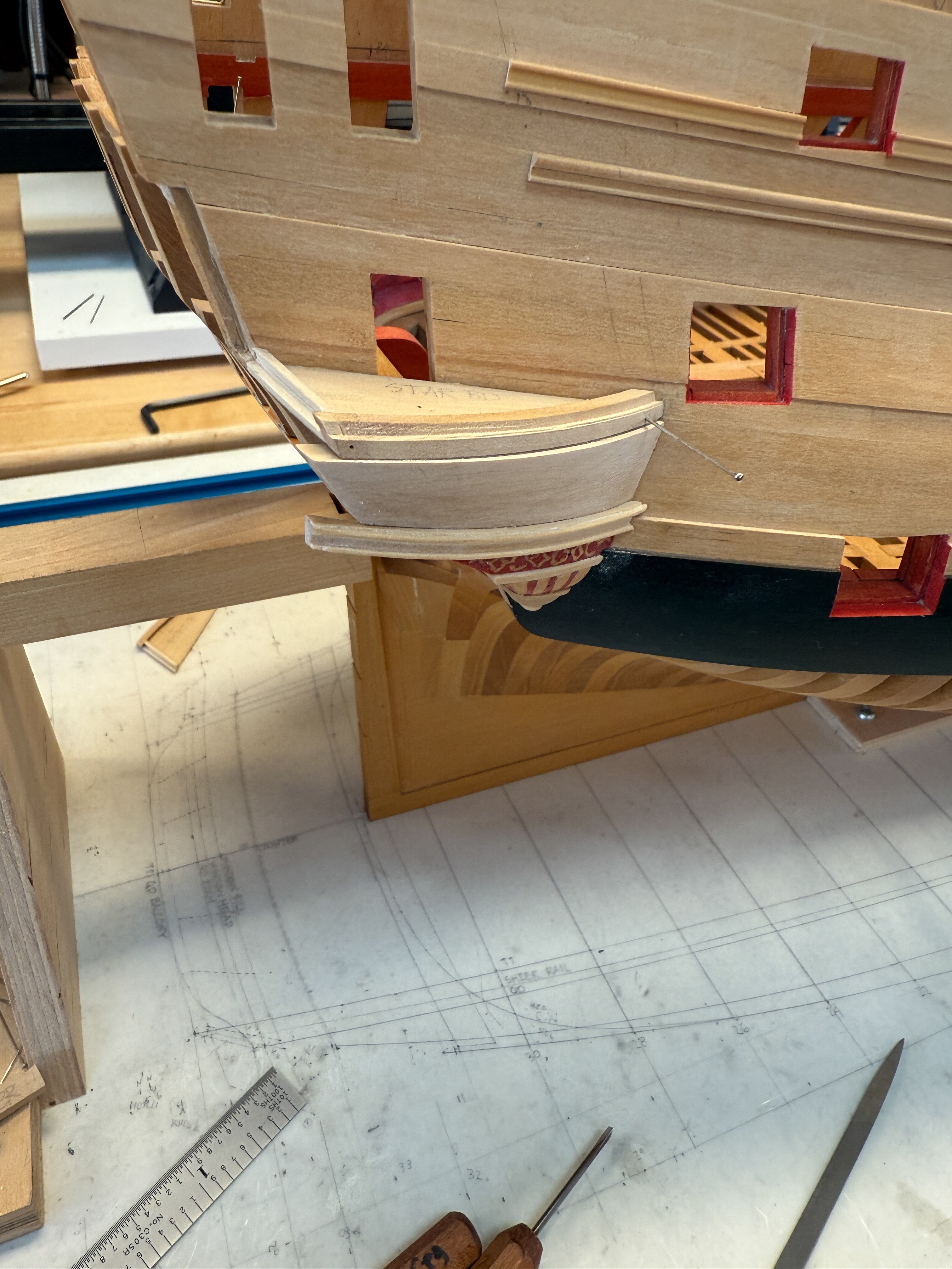
And here is the moulding temporarily spot glued in place, to check its fit and final size. This is also the final faux planked piece, cut out of boxwood after the basswood trial worked:

The flat piece faintly labeled STAR BD eventually goes away. This was a temporary former for getting all of the railings in their proper location and shape. The rabbeted rail is the base of the window frames still to come.

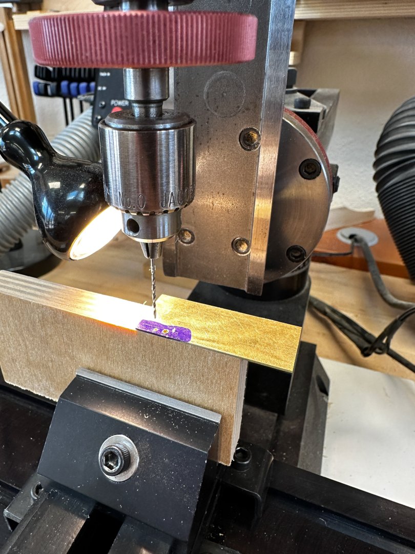
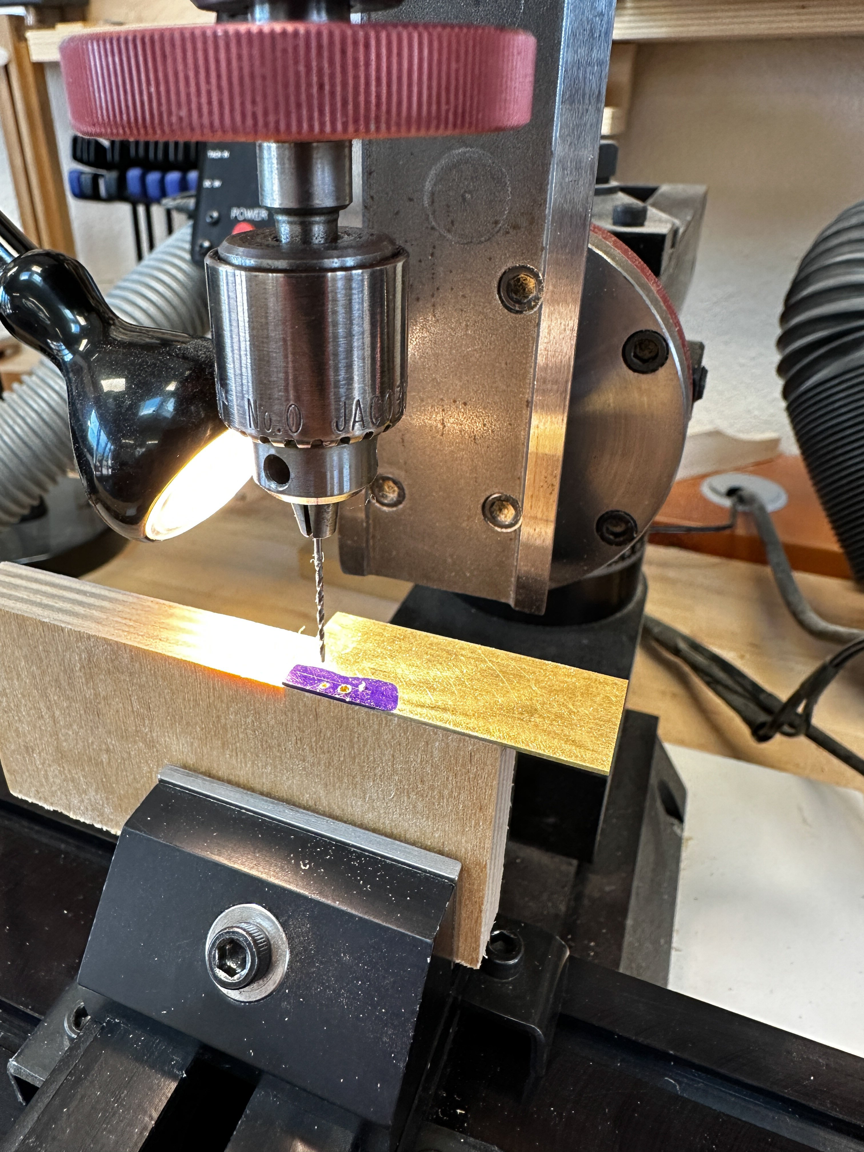
I have frankly struggled with making scraper profiles, until Chuck suggested I just make them out of brass rather than fussing with tool steel, softening to file and hardening to use. Each profile here is only going to be used for one or two parts, and then can be thrown away. So I worked out profiles based on the two semi-circles, and accurately drilled these in the brass blank on a mill:
Then I carefully filed the remainder of the profile using a needle barrette file and a jewelers clamp to ensure right angles to each side. This is important for the cutter to work the same in both directions.
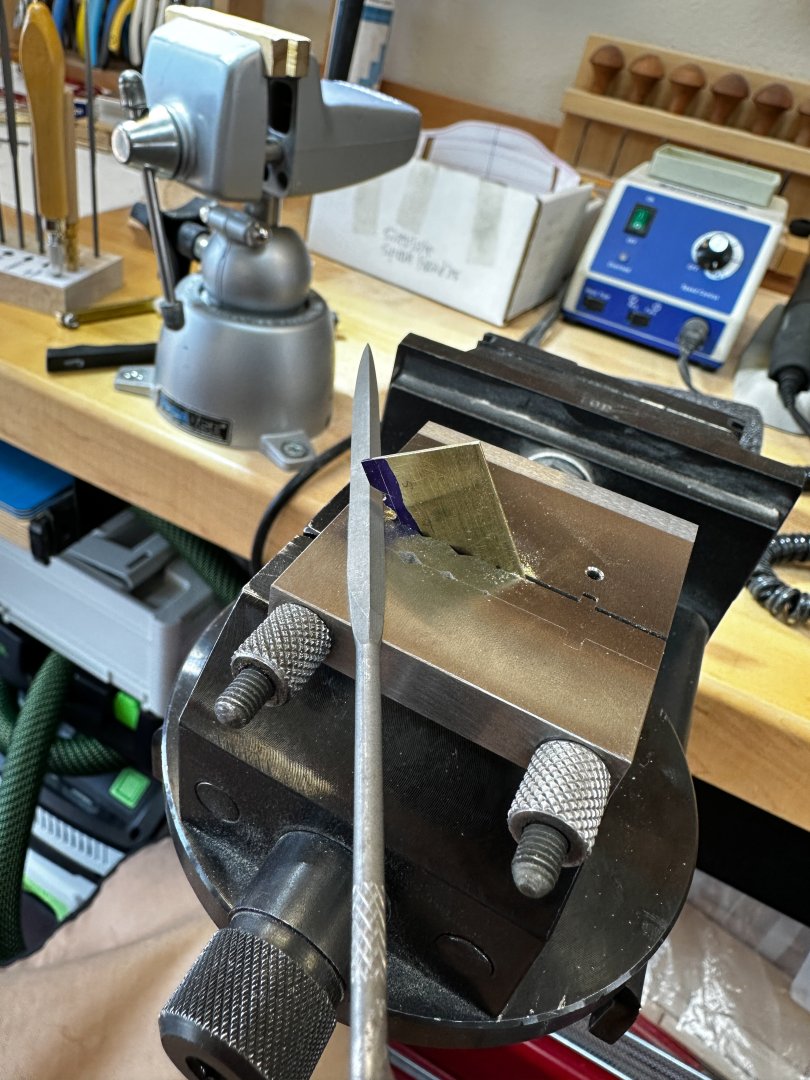
At last, I got accurate profiles with no heat treating challenges. Thanks, Chuck!
Now on the port side, and the big moulding along the knuckle here.
Best wishes,
Mark
This is fantastic! Thanks a lot for going into details on this!
-
18 hours ago, Ronald-V said:
Ok...a little photo report on how I approach it:
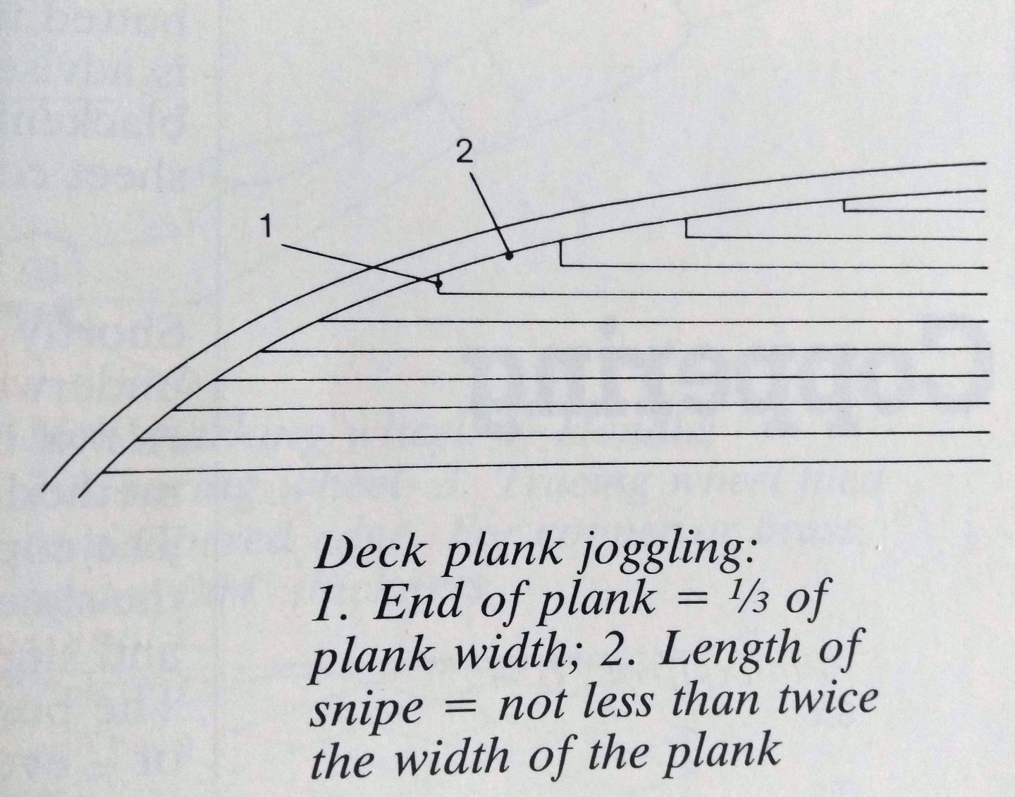
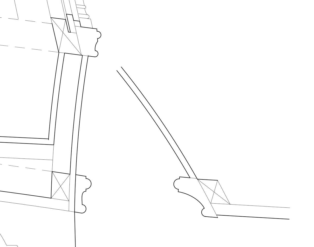
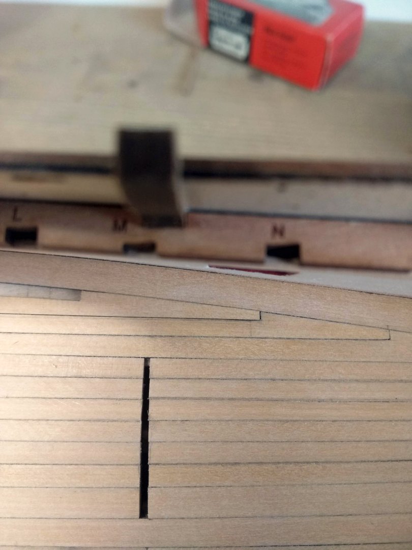
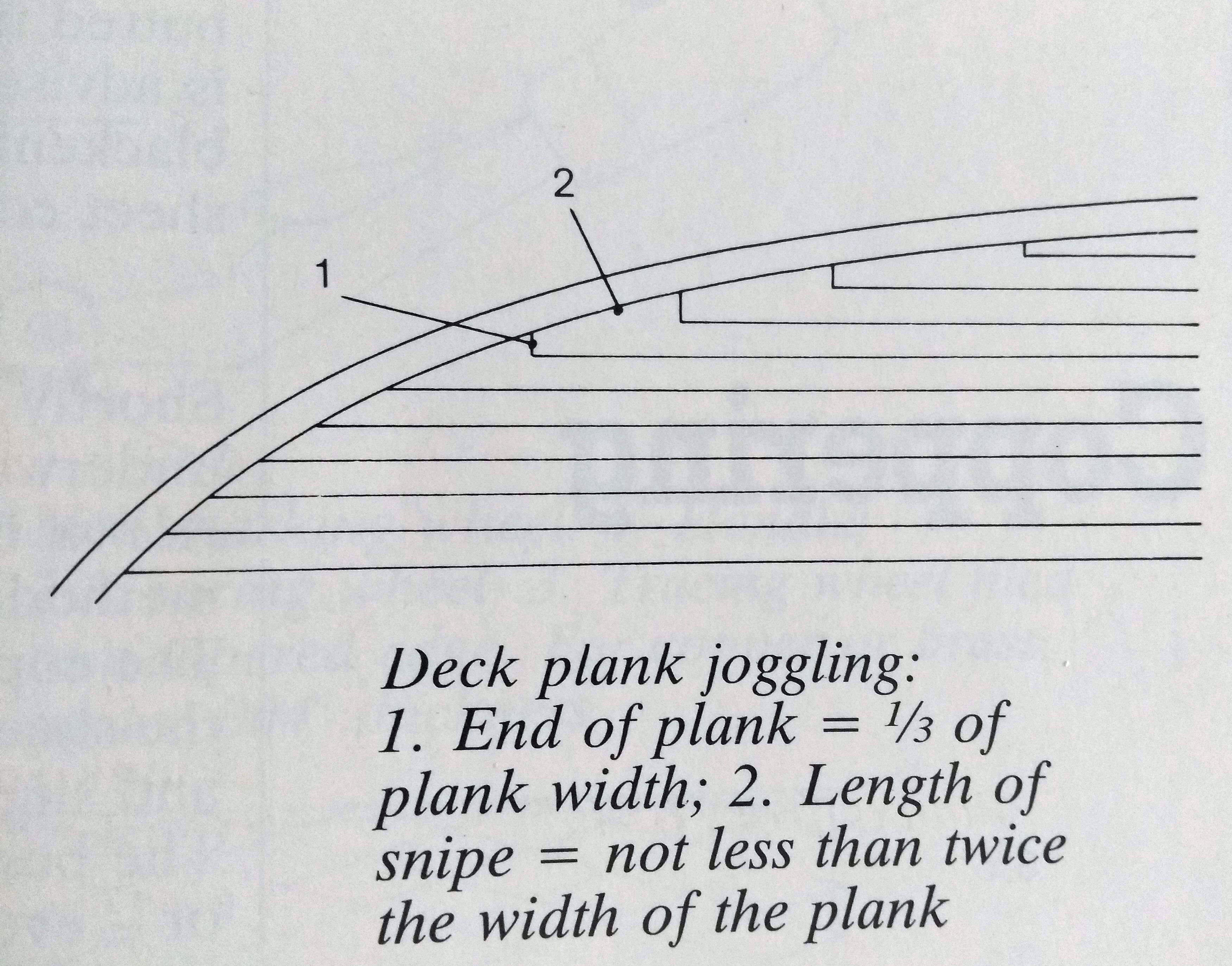
1) The rules for "Hooked scarph" planks are as follows according to "Wolfram Zu Mondfeld" in his book "Historic Ship Models". If it's 100% accurate? I don't know and don't care, I'm not that of a purist and if 1 source says it's this...it's okay for me.
2) First of all I have already made the first plank according to the above rules.

3)Then I take a plank that is a bit longer than I ultimately need and mark the 2 intersection points of the plank with respect to the margin plank. The bottom of this plank I naturally let rest in the pre-formed plank that is already on the deck.
4)Then draw a line between the two points. It doesn't have to be super precise because you are working towards the right shape. As long as you have a rough shape/angle.
5)Personally I use my disc sander for the first part...but whatever you prefer. The important thing is that you don't sand all the way to the line right away.
6)And then it's just carefully working towards the right angle. Here you can see that I'm sanding it down and fitting it, where the angle seems right, but needs to be sanded down a bit more to fit it completely. This is just done slowly, taking a little bit off each time. Sometimes you take too much off the angle, which creates to much space, but then you sand a little off the blunt point again, and that's how you play back and forth between the two. Sometimes everything works with the disc sander, but sometimes it also removes material too quickly and I take a sanding stick so that I have a bit more control. That's just finding out for yourself what you like.
But that's why you need some extra length...because it will not always be in one take and you need to sand a bit of the point, which makes the length shorter.

7) Another example where a bit too much has been taken off at the top left of the beveled side and the front needs to be a millimeter deeper. So here I try to sand the beveled side a bit straight until it fits nicely.
8 ) Like this...
9) Then you have the most important thing ready and you have to mark the board according to the rules. So the board that goes in here again has a minimum width of 1/3 of the normal width. In my case about 1.4mm (say... I'm not too strict about this myself)
10) Then you mark the rest of the board and cut away the vast majority first with a knife (or sanding).
What I found out after cutting is that if you try to cut the last piece crosswise it breaks off since you have no meat on the slanted side, so I do that last piece myself with a fine saw
11) Sanding stick to get to the actual needed size.
12)And the very last part of the "corner" I do with a sharp knife so you get a really good sharp corner. Personally I can't do that well with a file or sanding stick...so a knife works better...just make sure you cut off very small layers, because too much force and it breaks off.

13) Voila...
By the way...I don't know if this specific plank above that will go under the frames and doors, that it went like that in real life...but that doesn't really matter to me because it will be practically invisible when the upper deck is going to cover it. It will all be in the dark. But for me it is a good exercise so that I will have it in my fingers for the upper decks later.
I hope my explanation is a bit clear...not really a special method, but it works fine for me
")
Lovely! I will use this technique when I get that far 😃
-
Thanks @Knocklouder! I think my third hand may not work as it is clamped to the table. But I will see if I can make it work somehow.
-
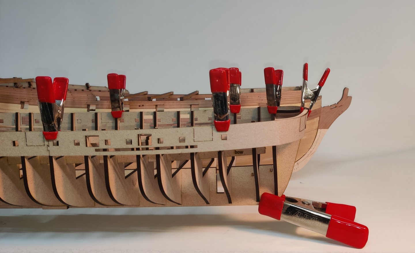
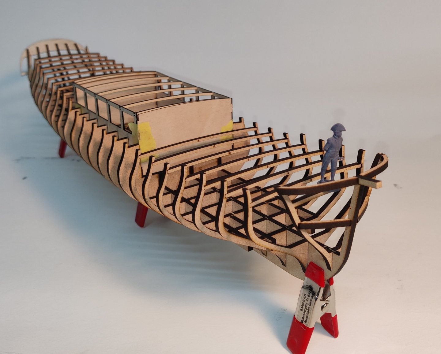
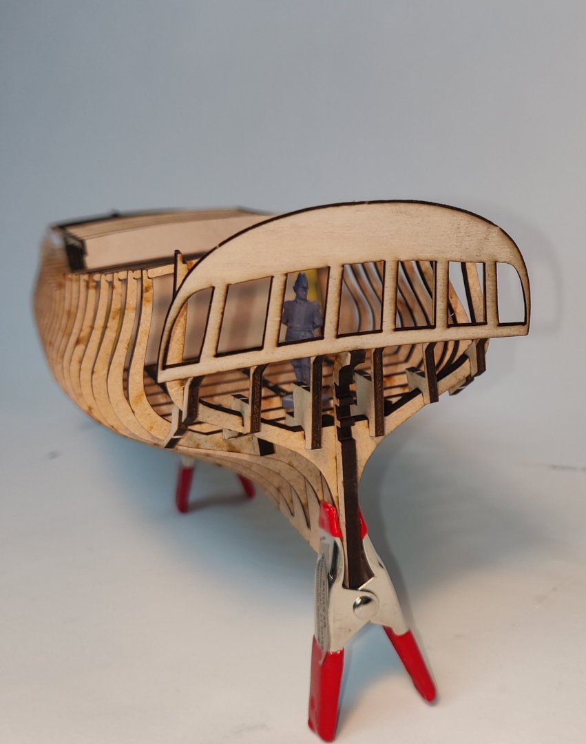
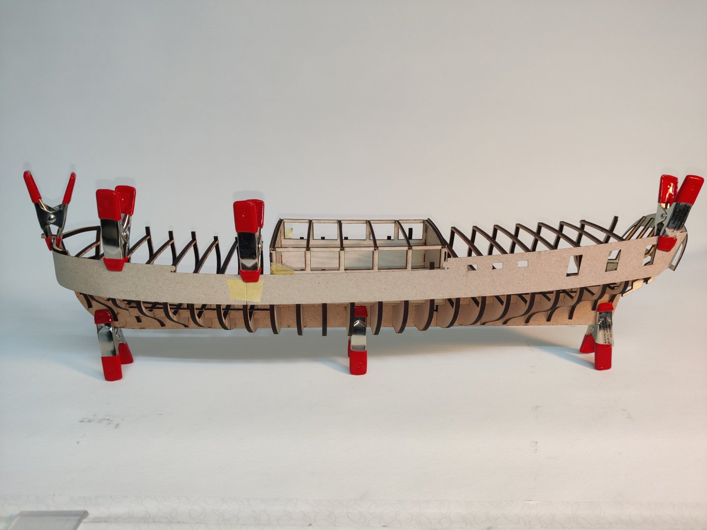
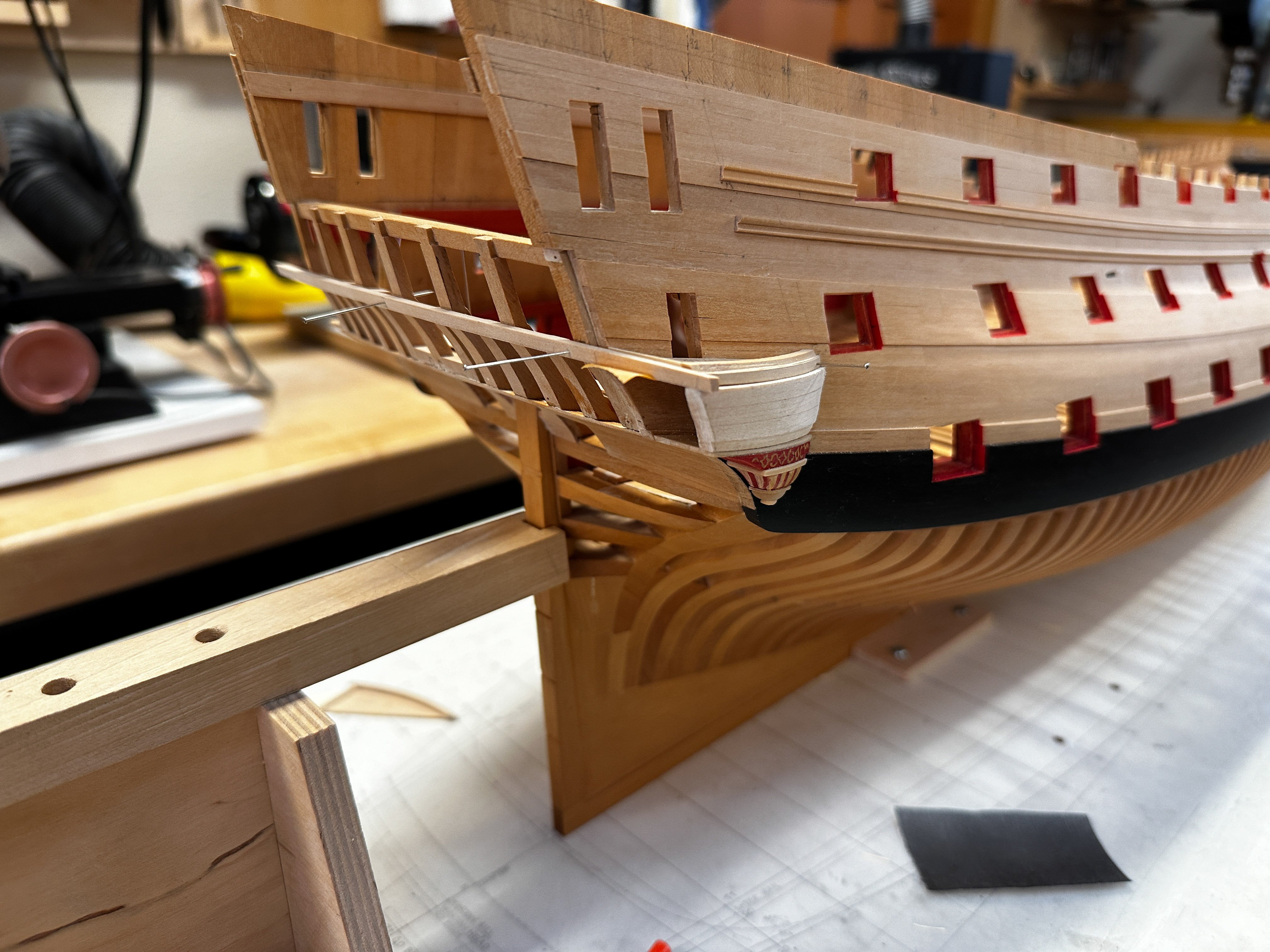
Log entry 14 - second layer planking start
I spent a few days fitting the upper outer bulwark patterns, clamping the pre-soaked parts, allowing to dry and then going over them with a hot iron. It is really not easy to get a reasonable fit on the modified prow shape. I don't know of it would habe bee better to cut them off at the sharp bend, but in the end, I think it became good enough. I may have to sand it a little to get it all good, but as it gets painted, that should be fine.
I also got the port side slightly lower that the starboard side, but only right at the sharp bend. I will just have to adjust the placement of the decorations slightly up on that side compared to the lase etched markings. I think it will be fine in the end.
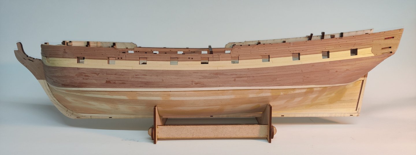
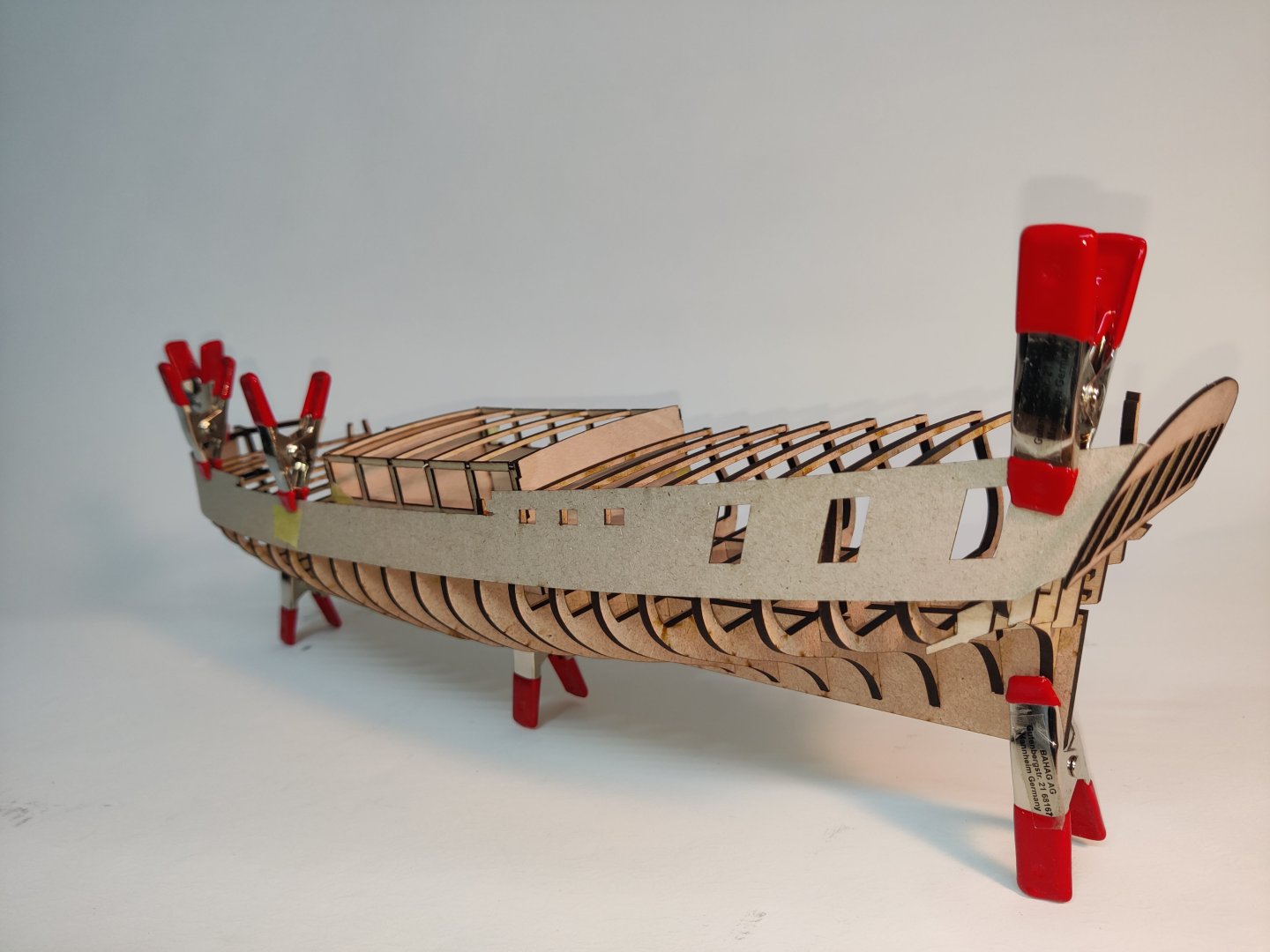
I then proceeded to add the first 4 planks on the port side. I had more or less decided to go with boxwood for the yellow stripe, but when I made the comparison on the model, I had a clear preference for the alaskan yellow ceder. I'm not quite sure why. There is less difference between the AYC and the maple, but it just felt right, so I went with it.
Here's how it looks now:

The 4th plank (pear) is also the location of the first of the two thin wales. It lines up nicely with the future elements at the prow, which is good!
I will now do this on the other side as well ( pre-cut upper bulwark is in place) and then it is time to draw a waterline - I dont have a tool for this, so I must figure out how to do this. Anyone have a good way or an easy DIY tool?
And then it is probably time to adress the small elephant that is the cut-away at the prow (in the bulwark around the bowsprit after the catheads). I have been putting off doing this until I had a way to be sure where the catheads went. I have that now and can use a paper cut out of the paneling patterns to get an exact template for the cut. It will only be more difficult to do it as I progress, so better do it now I guess....
BR
TJM
- Dan Poirier, Ronald-V, KurtH and 5 others
-
8
-
Log entry 13
I Have now proceeded with my plans to mix up the wood and hve made replacement parts for the outer keel patterns from 1 mm maple.

As the inner keel would show at the bow, I filed away around 0.7 mm and added a 3 mm maple strip (lying on the desk in the bottom right if this image)

I then added all the elements of both maple and pear:
I think the contrast between the woods look very good and if I can manage to get a straight waterline, I think this will be good in the end. If I can manage a helf decent planking job at least.
The maple is, ad expected, very hard, but that means it sands very well! I think I will take @Thukydides's suggestion and use it for the upper decks as well.
The bottle in the background in some of the above images are being used to form the stern piece - also slightly modified as my stern is a bit wider, so I had to cut out a new piece. I think I may plank the outer layer. I do have 0.5 mm pear sheet, but maybe it will be more consistent to plank it as all other non painted parts will be planked.
Thanks for following along!
BR
TJM
- cotrecerf, KARAVOKIRIS, Ronald-V and 5 others
-
8
-
8 hours ago, catopower said:
@TJM I see there are two versions of QCAD available. Are you using the regular QCAD Professional or is the QCAD/CAM version?
The regular pro version. I think I paid $40 or something like that.
-
3 hours ago, Thukydides said:
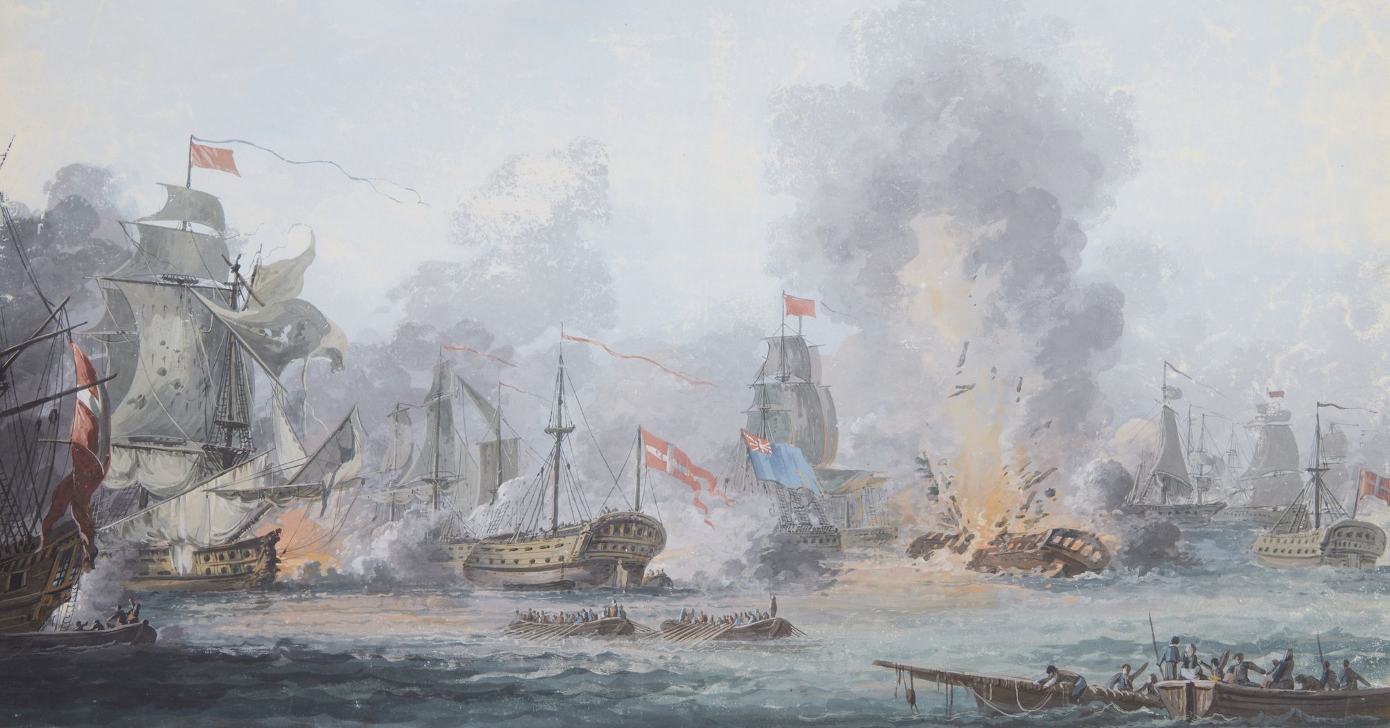
I like the ideas you have. I was looking at contemporary depictions of Danish frigates and I found this one from the battle of Copenhagen in 1801 at the RMG (I have copied the relevant potion):
https://www.rmg.co.uk/collections/objects/rmgc-object-12020
You can see the yellow band is actually a bit wider than you have it. It seems to me (a general observation on the many frigate paintings I have looked at) that when the switch from painted decorations to just black and yellow came they tended to make the yellow band wider. You might want to consider bringing the yellow band up to the next molding sand potentially make the molding black. Granted this is a bit later than when your ship launched.
The ship in the painting appears to have built up quarterdeck bulwarks hence the large black band on the top.
I agree with Ronald, less is more. If you are using the maple for below the waterline then I would also use it for the deck as they are both meant to be "whiteish".
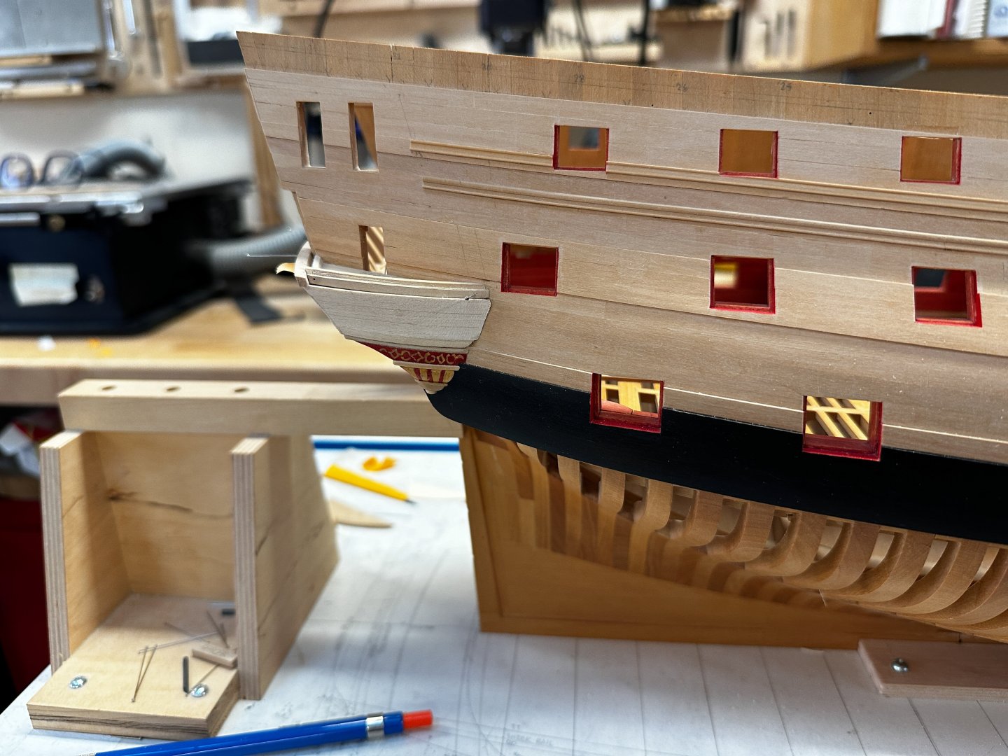
Thanks! I tend to agree, that the one line is a bit to thin, which is also why I was considering extending the yellow to in between the wales as well. I don't think it should be extended upwards - it seems pretty consistent that the upper part of the yellow is more or less aligned with the upper edge of the gunports or a bit below this. There seem to be a clear 'division' in the plans that match those on the Sphinx very well.
When looking at the painitng of Søerideren, it seems the broad yellow line is actually because the two wales were also yellow on that ship:

I don't know how comon this was, but if following this, the mockup would look like this:

The trouble is just that I don't really care for this look! And I know for a fact that the two thin wales for each gundeck that was common on the Danish ships of all sizes were often painted black or very dark brown. So I think I will stick to that. But the dilemma is then to decide whether to keep the line think - I agree with Ronald that it looks more harmonious - or if I extend it down between the wales, as that is maybe more realistic as Thukydides points out!
Here is a few more images to compare with:


On the first and third image, the battery lines does not look that thick. But all of these may depict slightly later periods than my ship. I don't know how much it changed in the 20-30 years in question. After 1807, white lines became common, so it can't be much more than 30 years after Christiania was built.
Regarding using maple for the deck, I had actually not considered that! That may be a good option, thanks for that input!
2 hours ago, Ronald-V said:Maybe it's a bit difficult to try to decide everything in advance. Unless you need to order all the wood in advance, then it's a different story. But seeing wood on the ship will be different then artificial colors on a screen. I do think it only can get you so far...But some people are better in visualizing then others and maybe you are one of them.
True! It never looks quite right in the digital images. I have all the wood in stock so I can wait a litltle with the final desicion, but I will need to make it soon-ish.
Thanks a lot for your inputs, lots to consider and more comments are most welcome if you have any thoughts on my considerations 🙂.
BR
TJM
- Thukydides, cotrecerf and Ronald-V
-
3


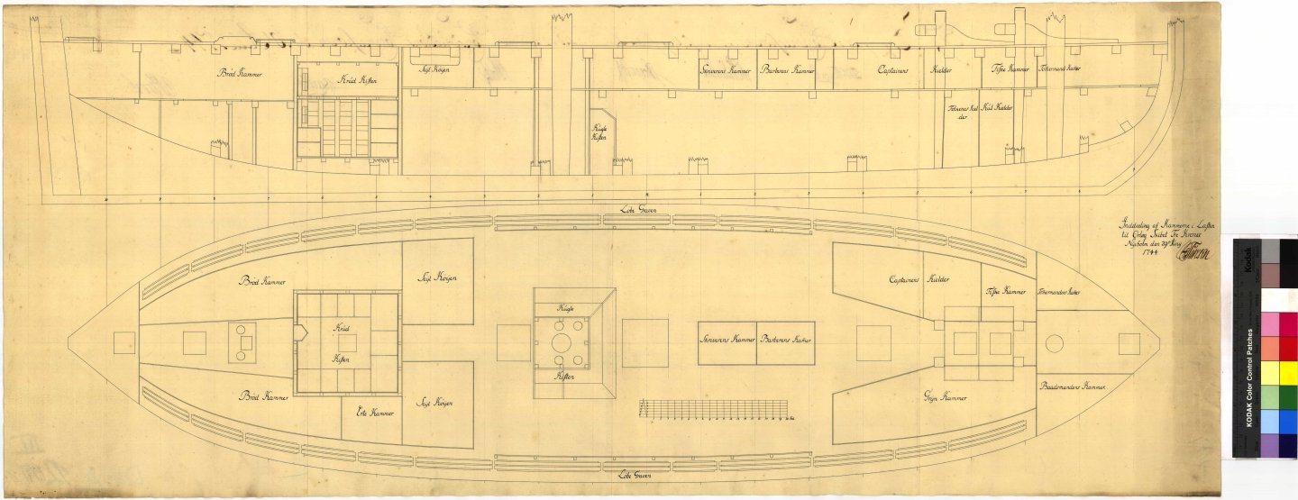
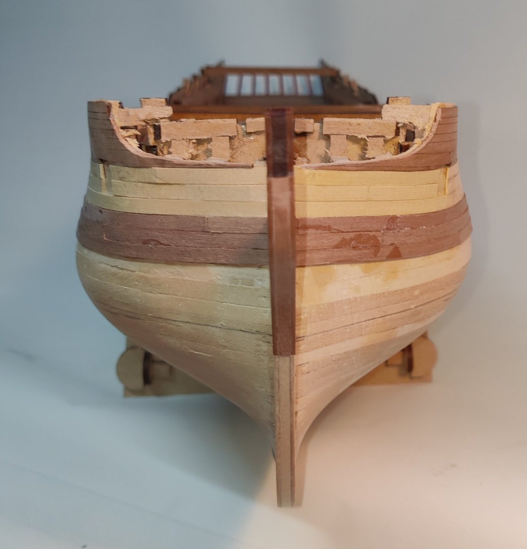
TRE KRONER 1742 by Beckmann - 3"/8' scale - Transom-Model
in - Build logs for subjects built 1501 - 1750
Posted · Edited by TJM
Hi Matthias,
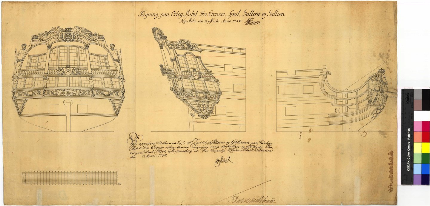
Regarding the cabin details, have you seen this drawing from the Danish archives?
I believe it shows the three decker Christianus Sextus from 1733 by Barbé's predecessor Benstrup.
It gives a good hint of what the decor in the cabins were like at the time!
EDIT: I just realised that this was the image you posted part of a few posts ago, sorry! And you are probably right that it is the Sophia Magdalena!
BR
TJM