yvesvidal
-
Posts
3,644 -
Joined
-
Last visited
Content Type
Profiles
Forums
Gallery
Events
Everything posted by yvesvidal
-
 What great work. You are producing another little marvel, here. Yves
- 50 replies
-
- 2
-

-
- Marie Felling
- tug
- (and 3 more)
-
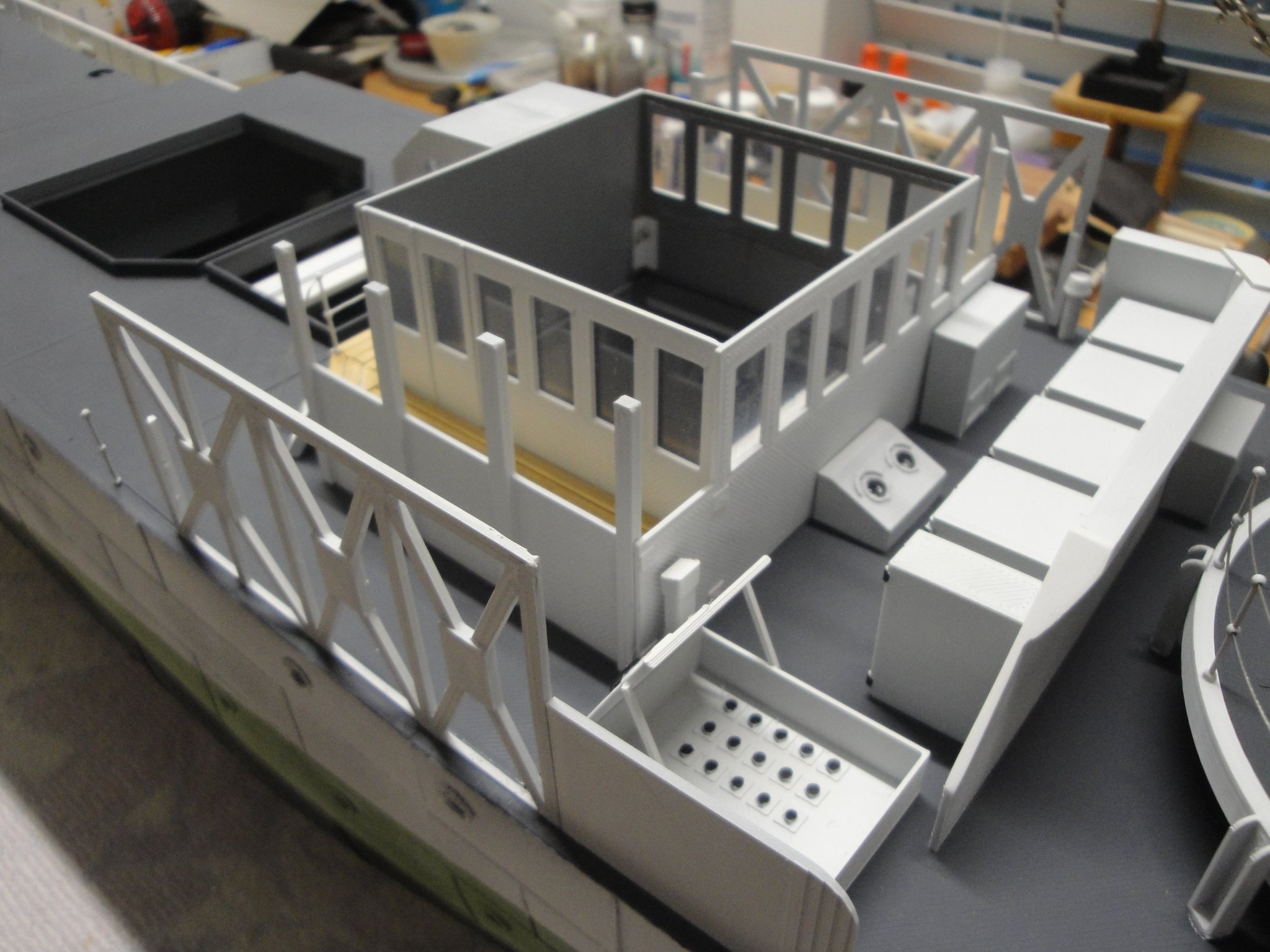
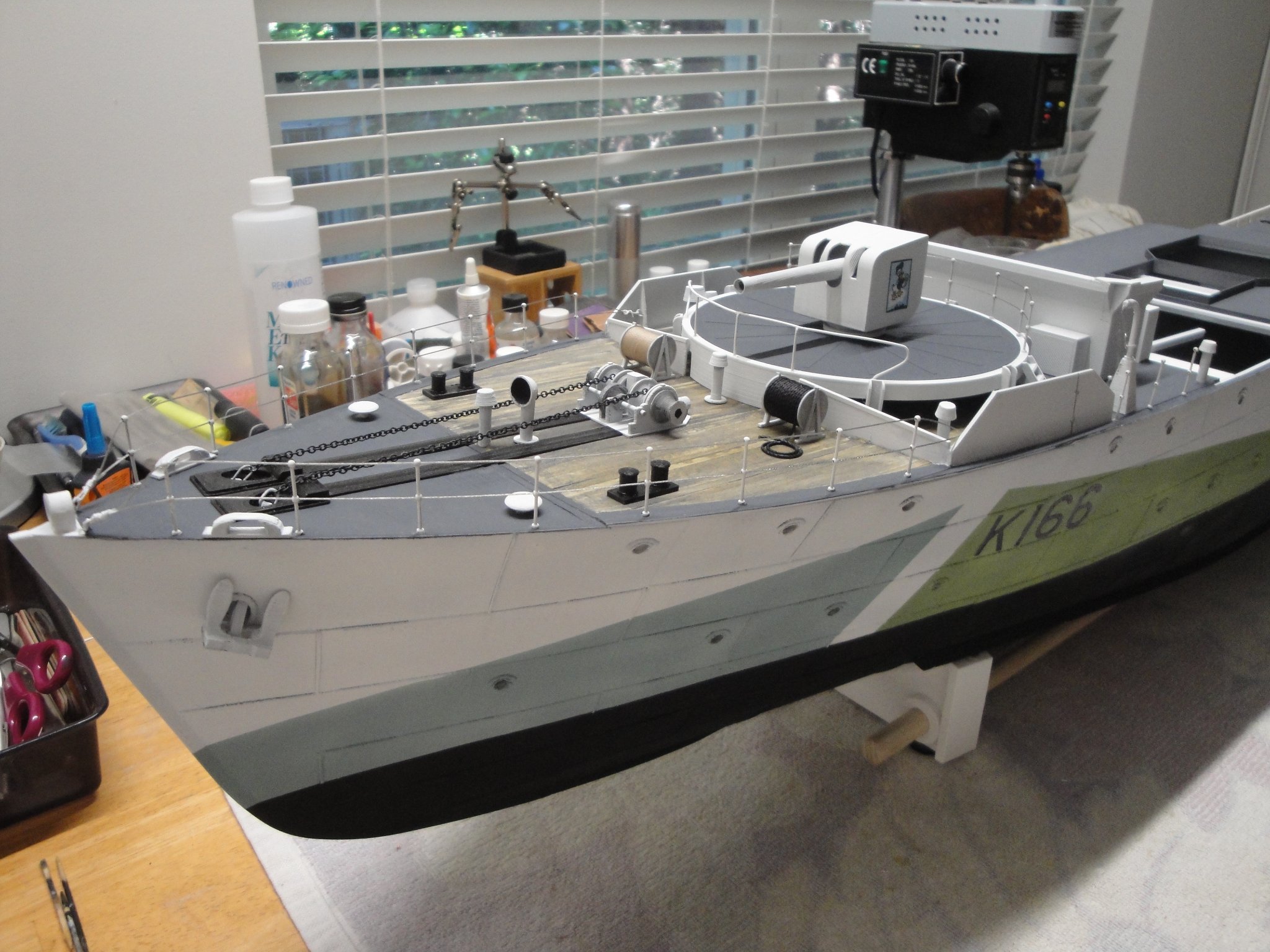
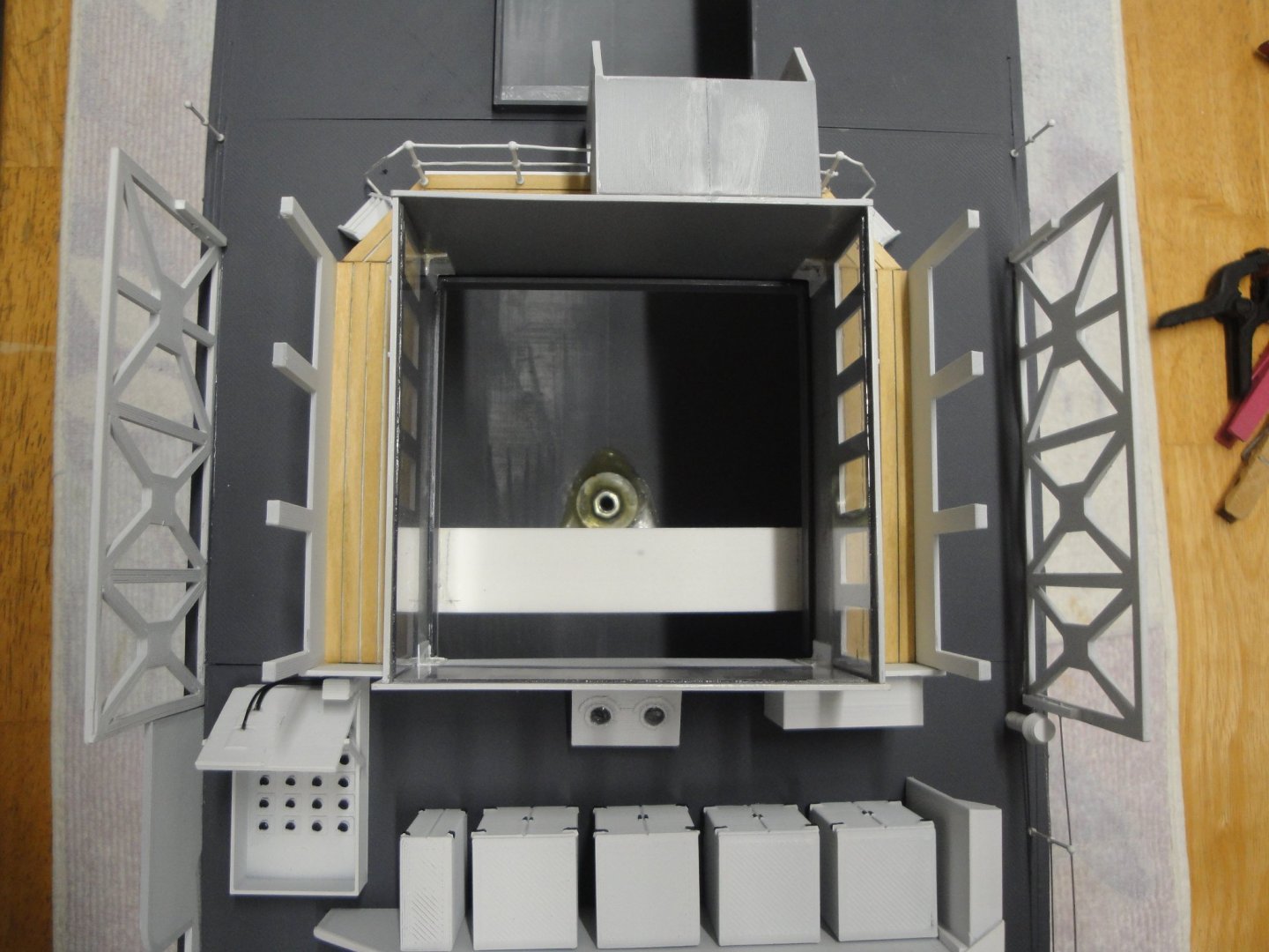
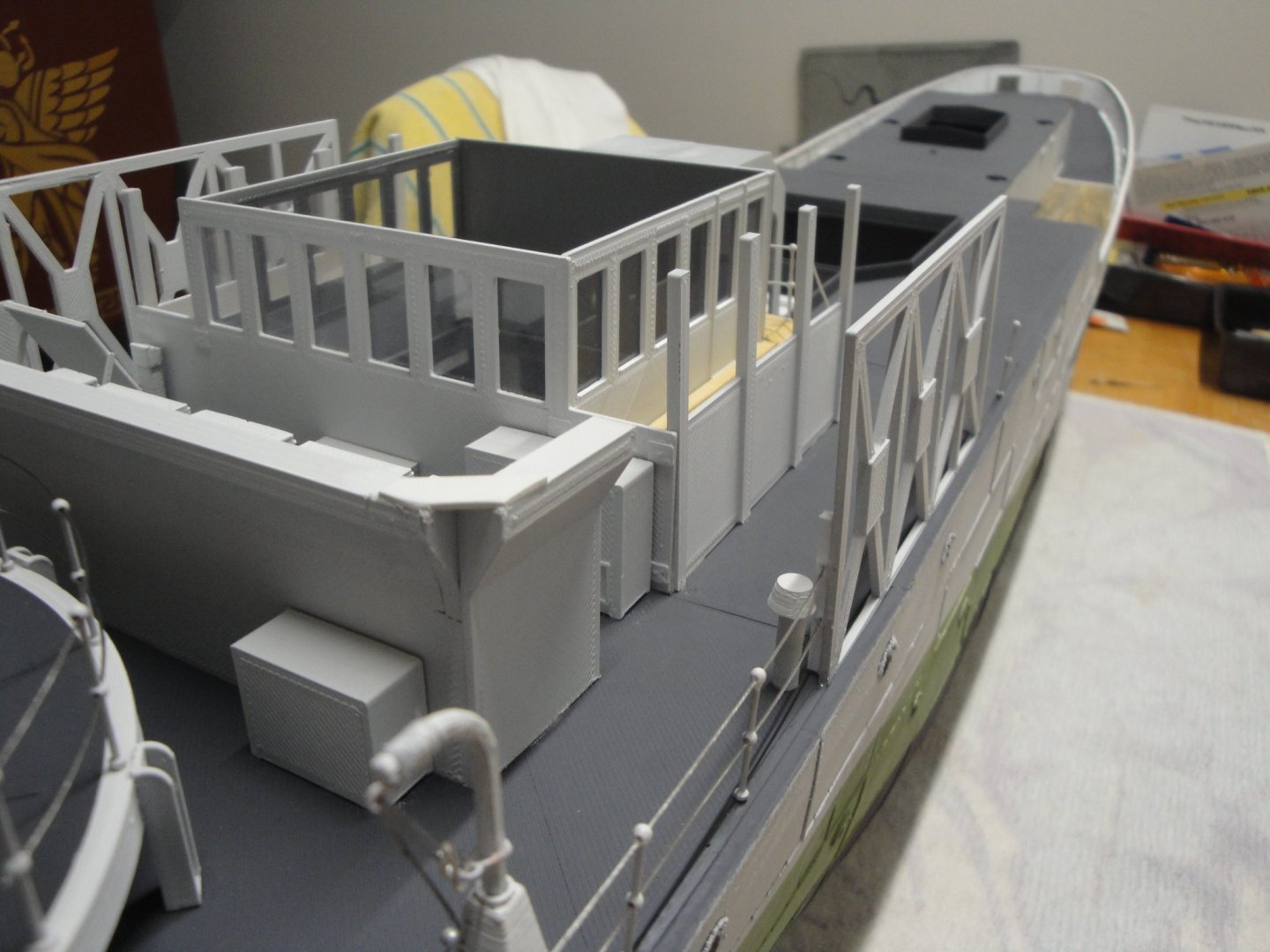
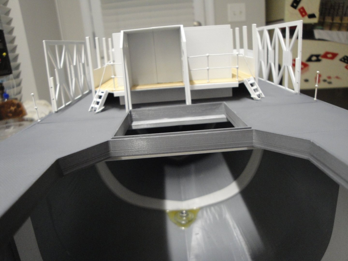
Moving along with Module #3A: This one was easy as all was prepared ahead of time... :-) Notice the railing above.... It is starting to look like a Corvette..... Next is Module #4: the galley, the smoke house, the mast, the dinghies and all kind of details..... Yves


- 321 replies
-
- 20
-

-
-

-
- Finished
- Flower-class
- (and 1 more)
-
Mog, This diorama is wonderful and full of life. It is so realistic that I expect these little characters to start moving. I would have loved to be on that remote island of the Pacific. Yves
-
Those extra details are really paying off. Fantastic job. Yves
- 127 replies
-
- 1
-
-
- Bowdoin
- Arctic Exploration
- (and 3 more)
-
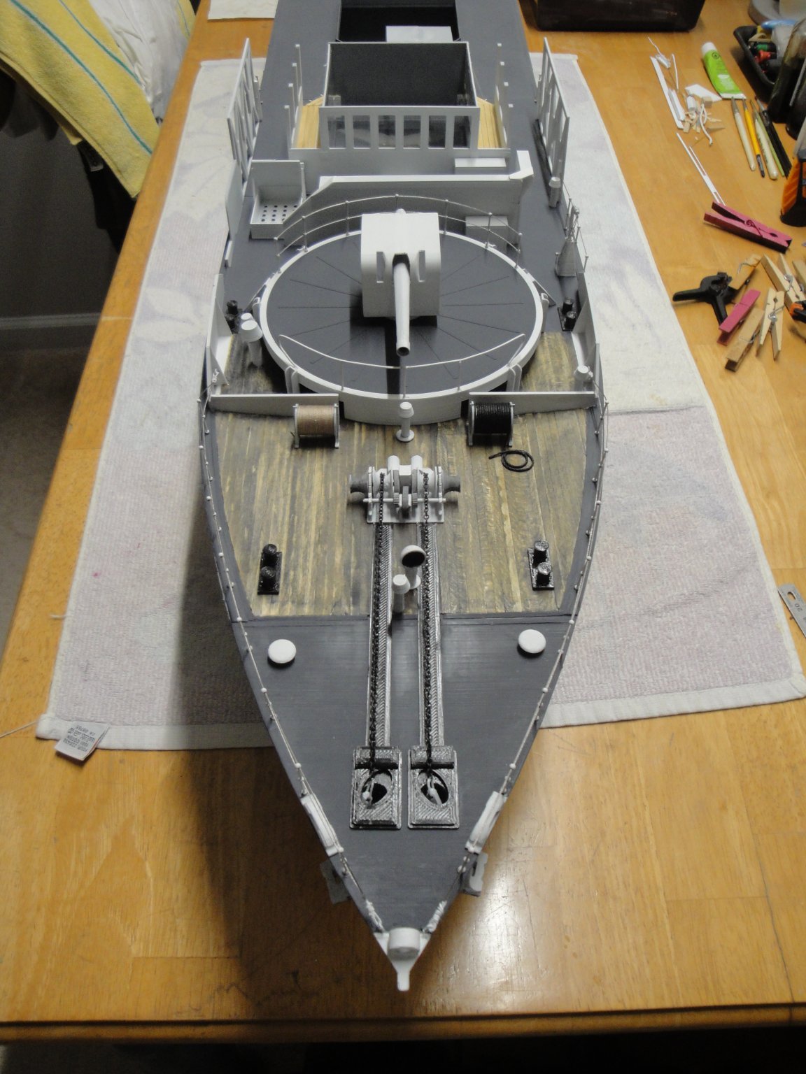
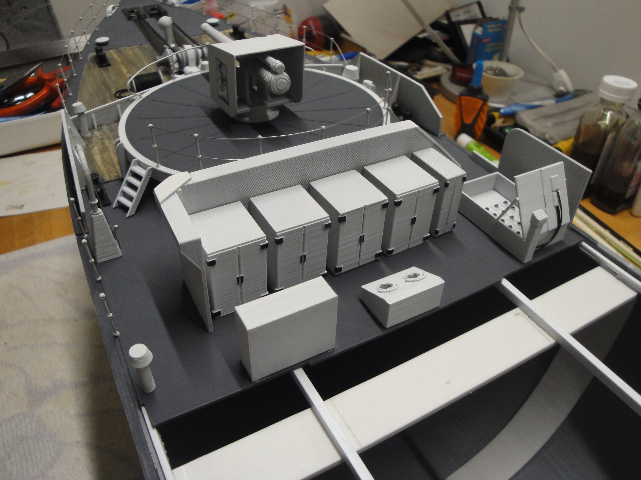
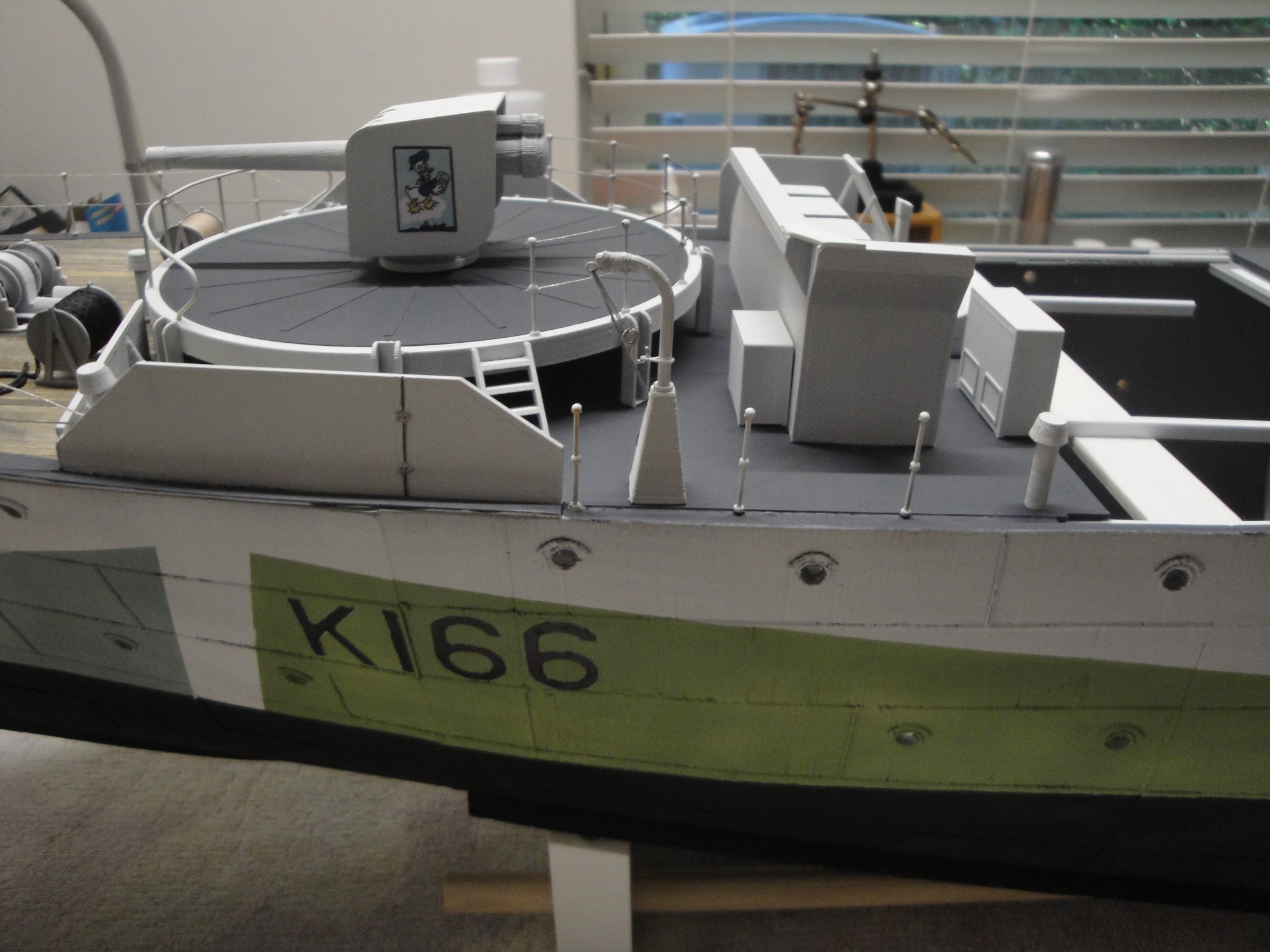
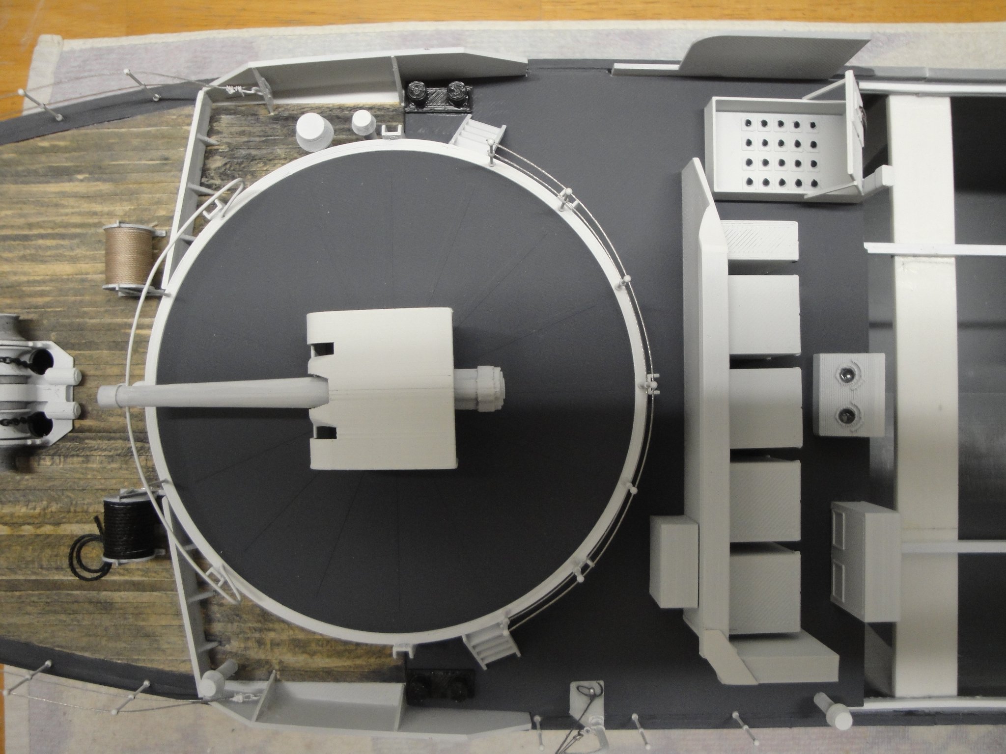
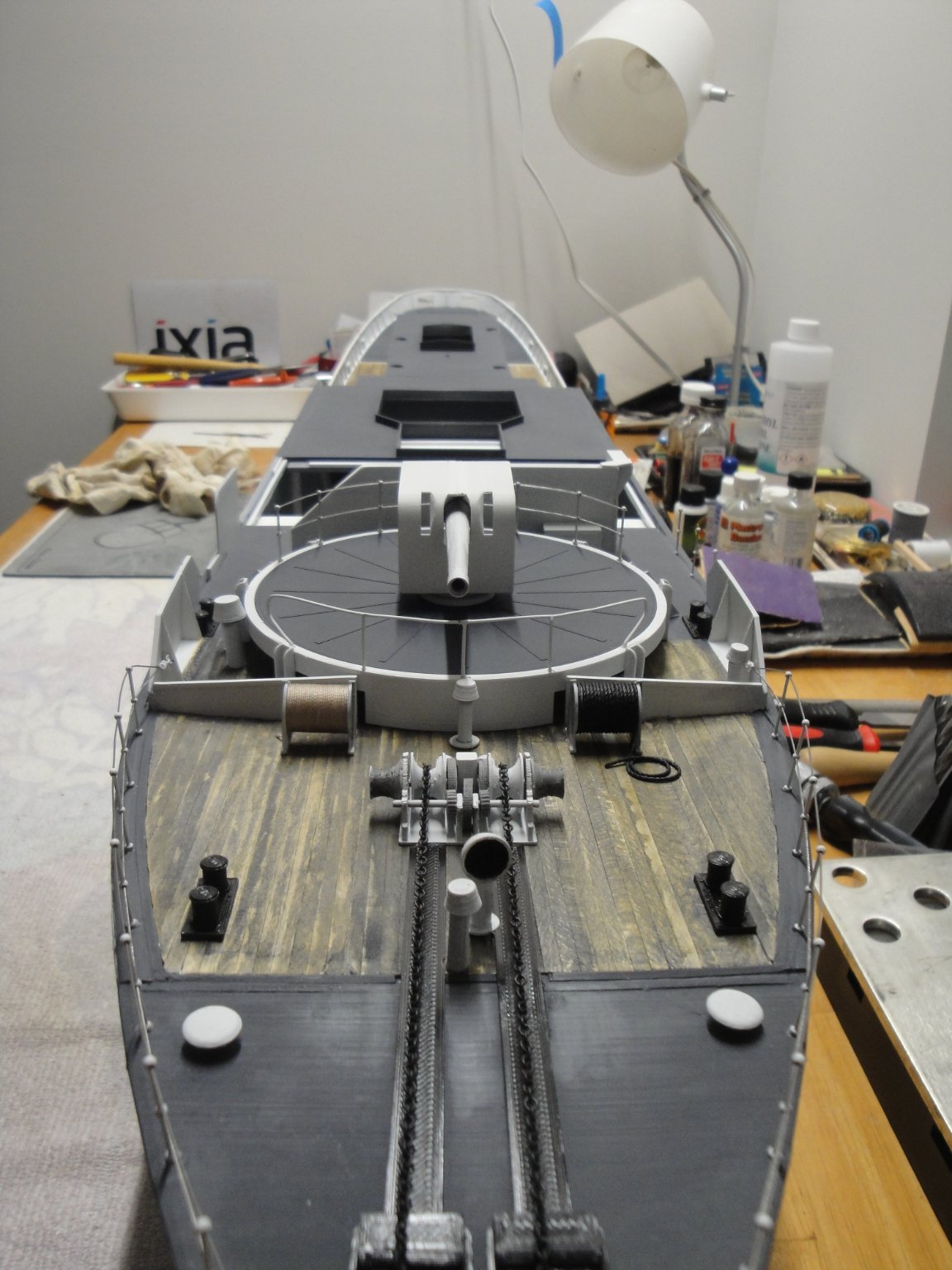
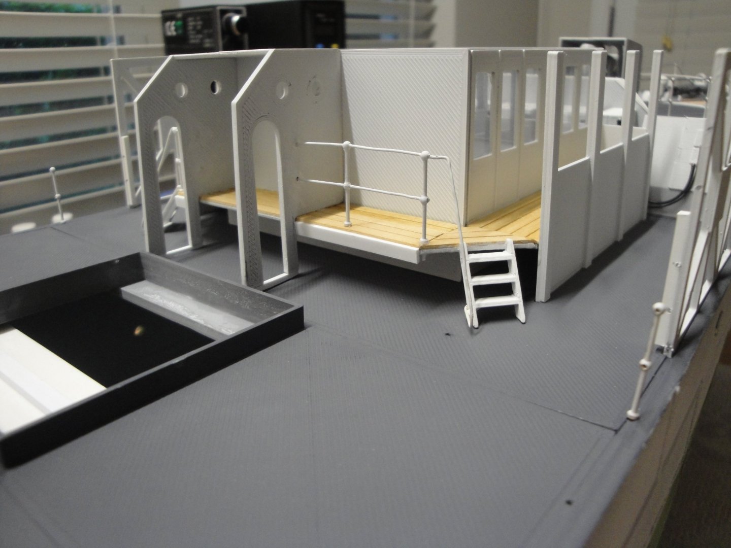
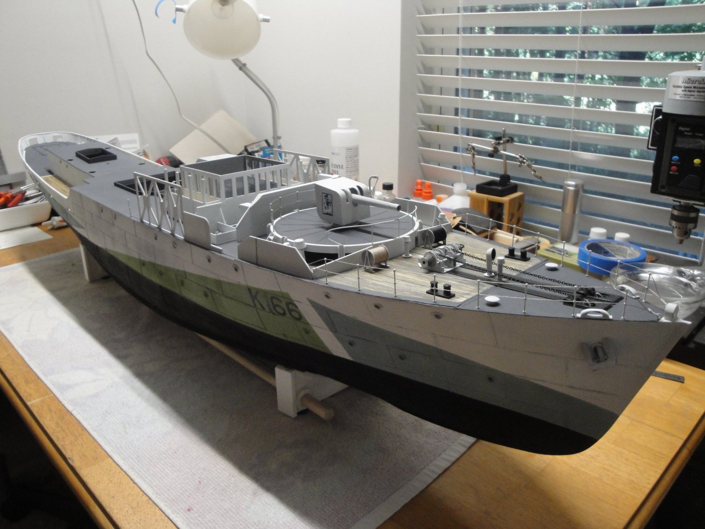
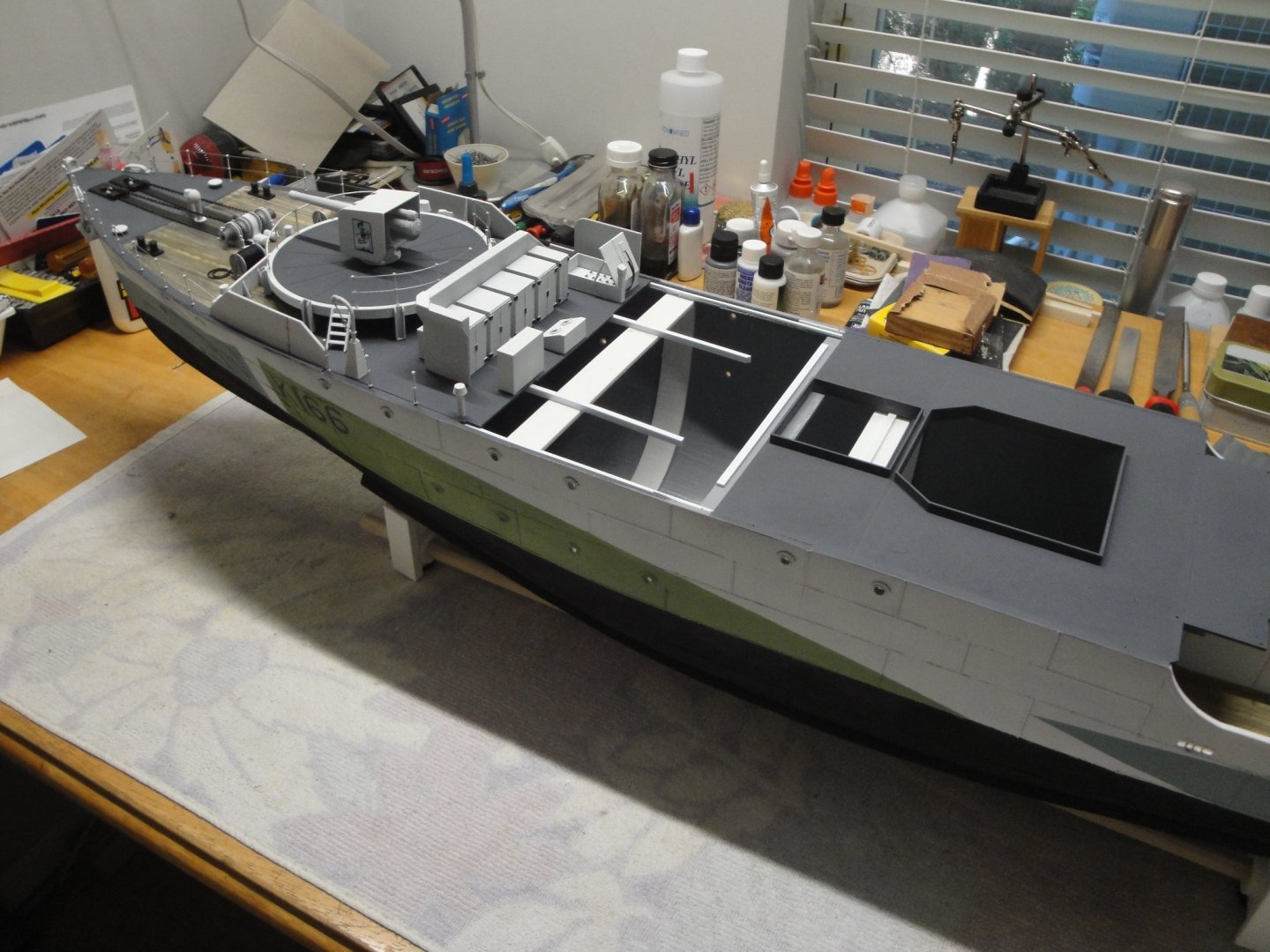
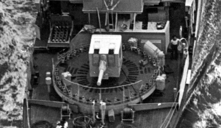
I realized I had not posted in a little while. The 2nd module is pretty much finished. The railing will be completed, once I glue Module #3. Lots of cabinets to store ammunition and rockets, for the Hedgehog and 4 inches gun. A little crane to embark the ammunition. The gun with its Donald Duck insignia. Next will be module #3A, the wheel house. There is of course, plenty of room for extra detailing. I really do not have the time and skills to extend this kit with PE and other details. I am still trying to see what can be done with the Virtual kit plus some extra parts here and there. Access to a Resin Printer would have been much better for the gun, but that can be retrofitted later on, as the gun is removable and parts can be printed again, with higher resolution. Yves


- 321 replies
-
- 11
-
-
- Finished
- Flower-class
- (and 1 more)
-
Beautiful yawl. Thank you for doing this very unusual model. Yves
-
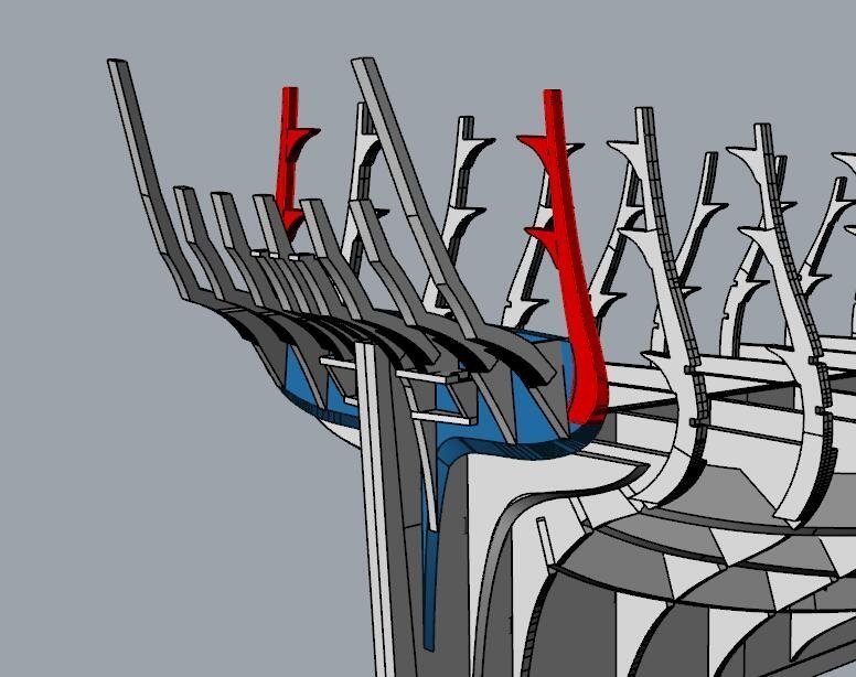
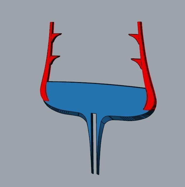
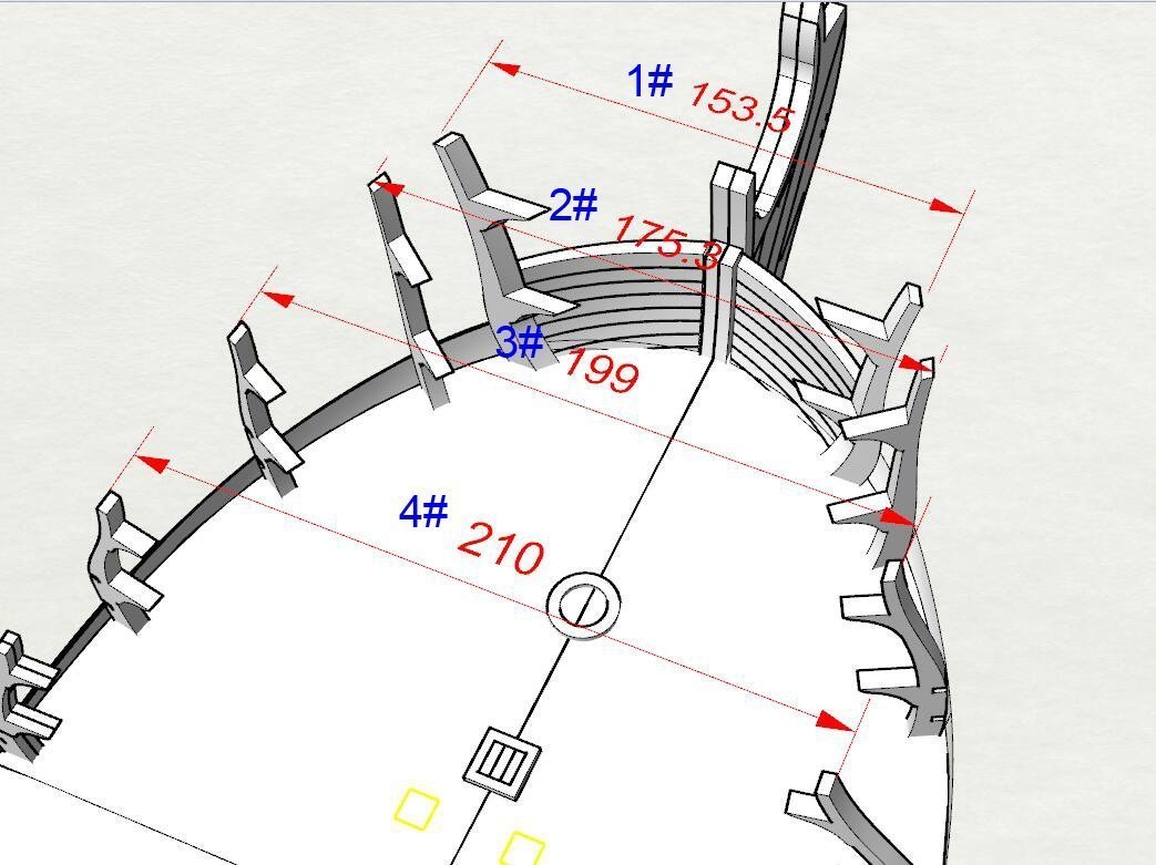
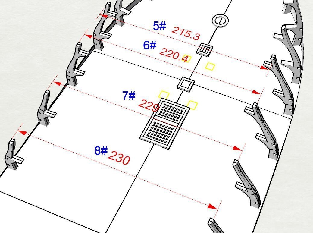
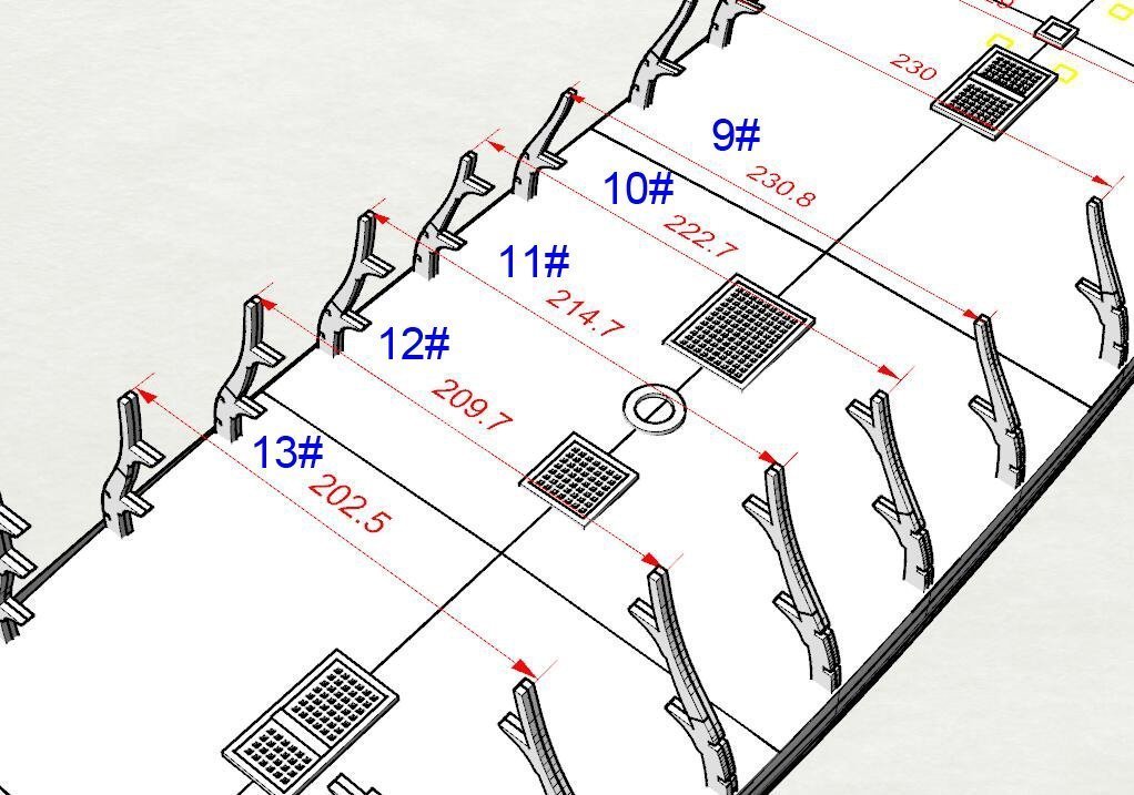
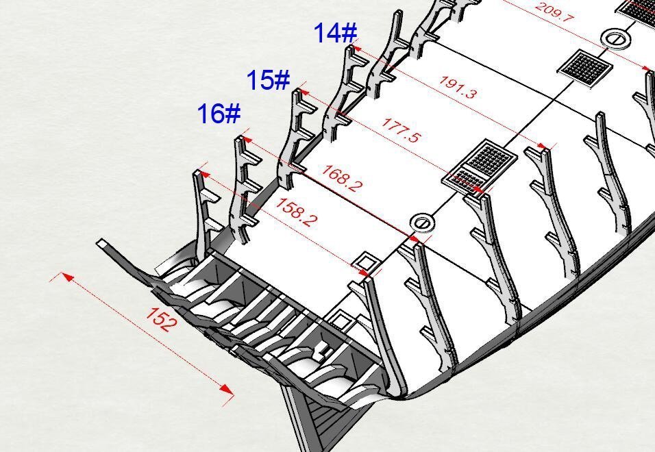
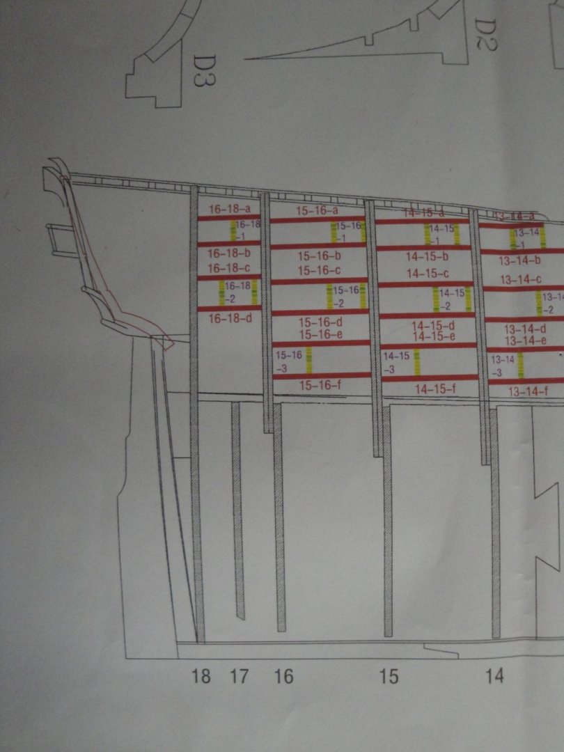
I am publishing some of the information that Tom provided me with, in the hope that it may help the modelers that will attempt this kit. The first part is related to the building of Bulkhead #18.The bulkhead is 5 mm thick, whereas the futtocks assembly will be 6 mm to 7mm thick. There will be some extra wood material and this should be placed towards the stern, as depicted by the drawings below: The second part is related to the distances between the futtocks, when you build the bulkheads. Here are the precise measurements given to me by Tom. I realized that I will probably have to de-construct and re-construct Bulkhead #4 since I am 5 mm too short. All the above is incredible material and I wish it would be included with the instructions booklet. Tom indicated to me that some information was removed from the current booklet, because of the Chinese piracy on his kits. Yves Yves
-
It is. Great job. I can see that you are a cheese lover.... with the lid of a Petit Brie. Yves
-
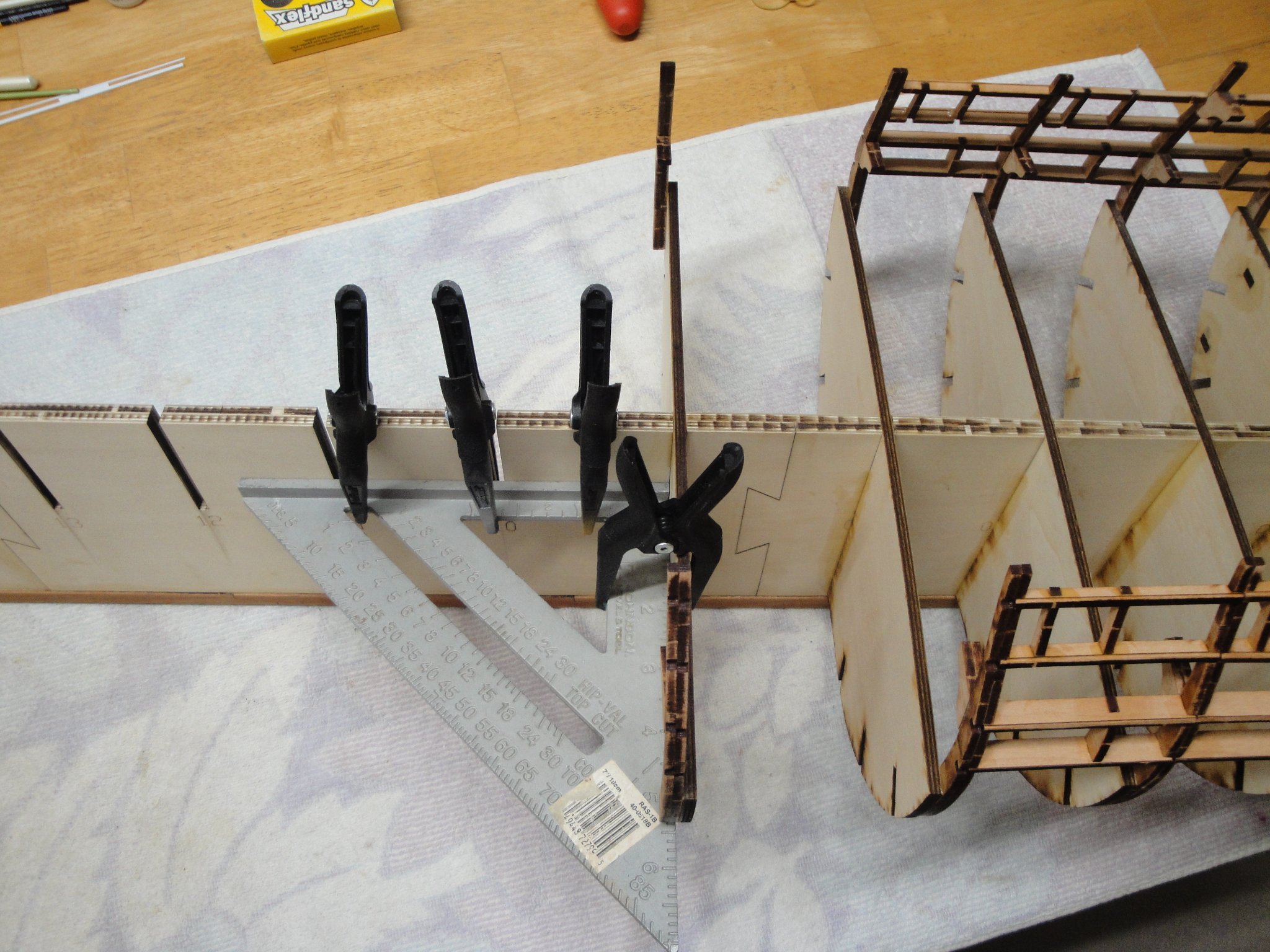
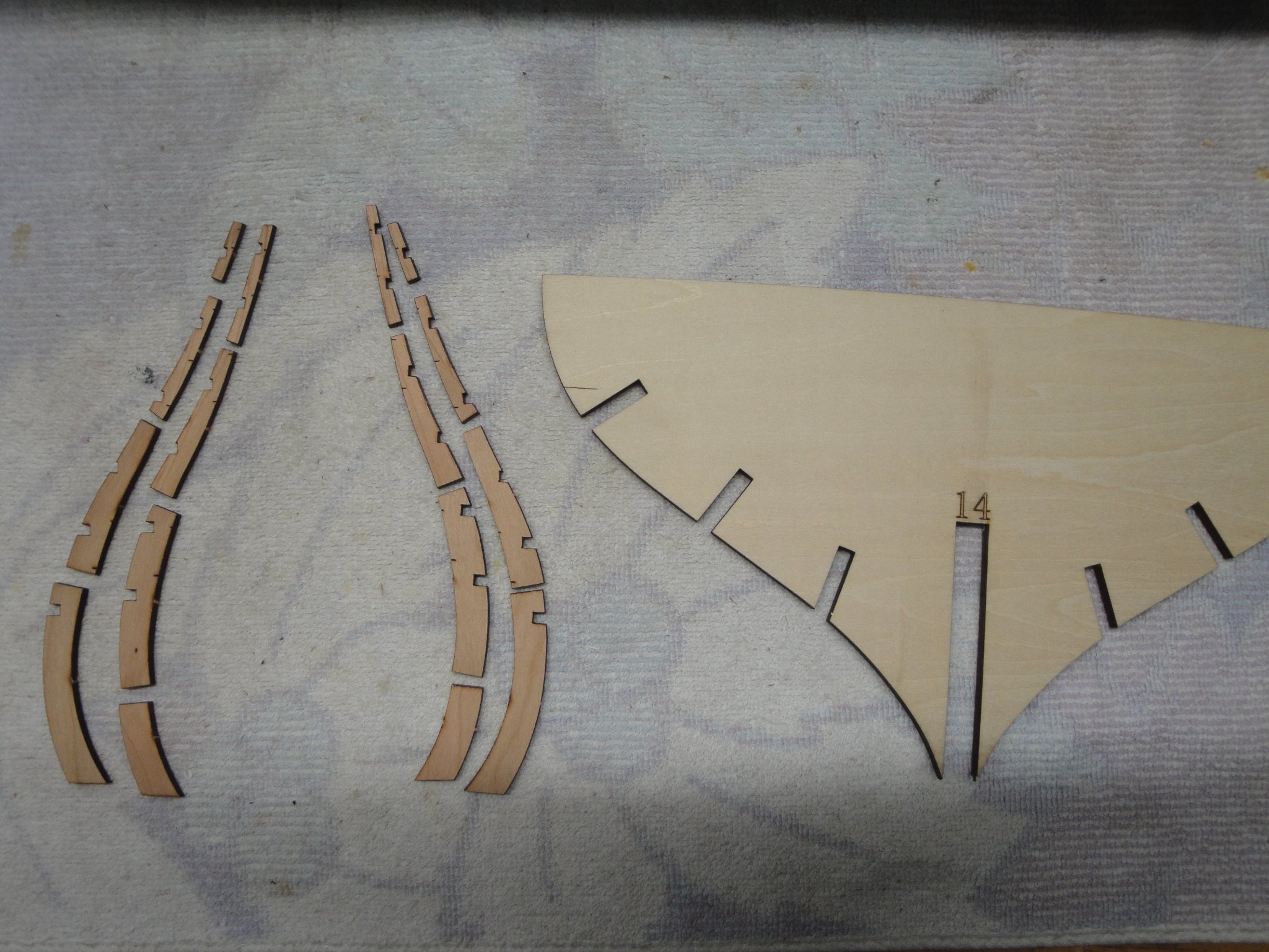
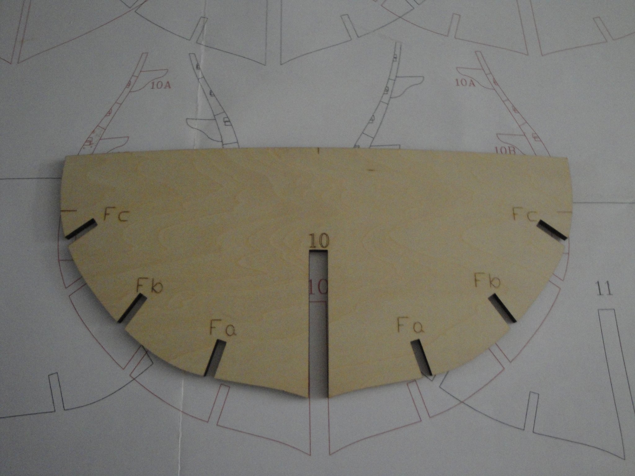
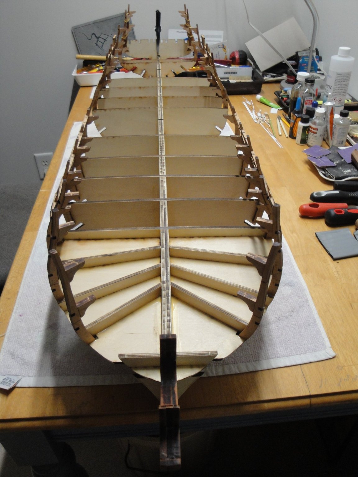
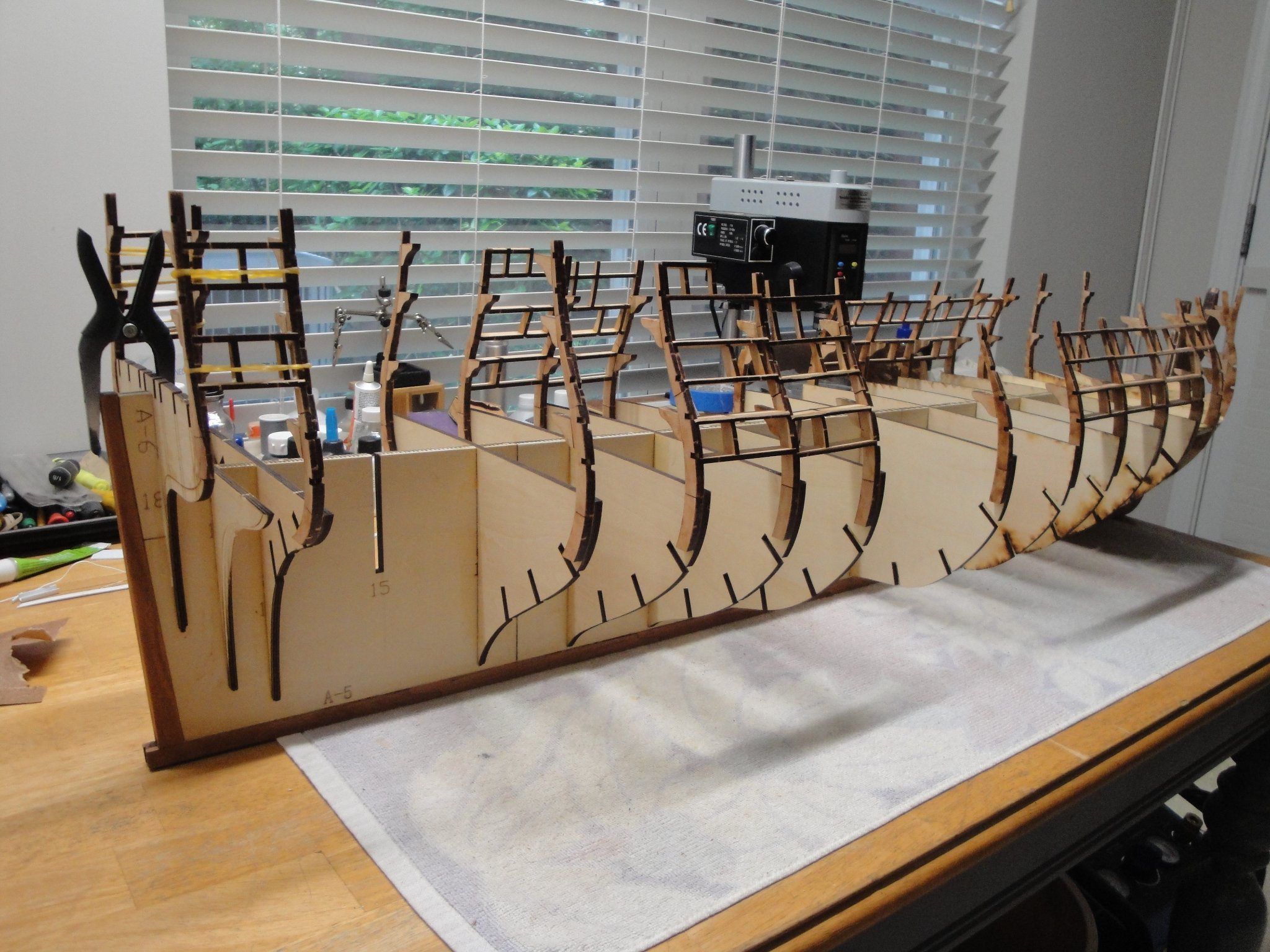
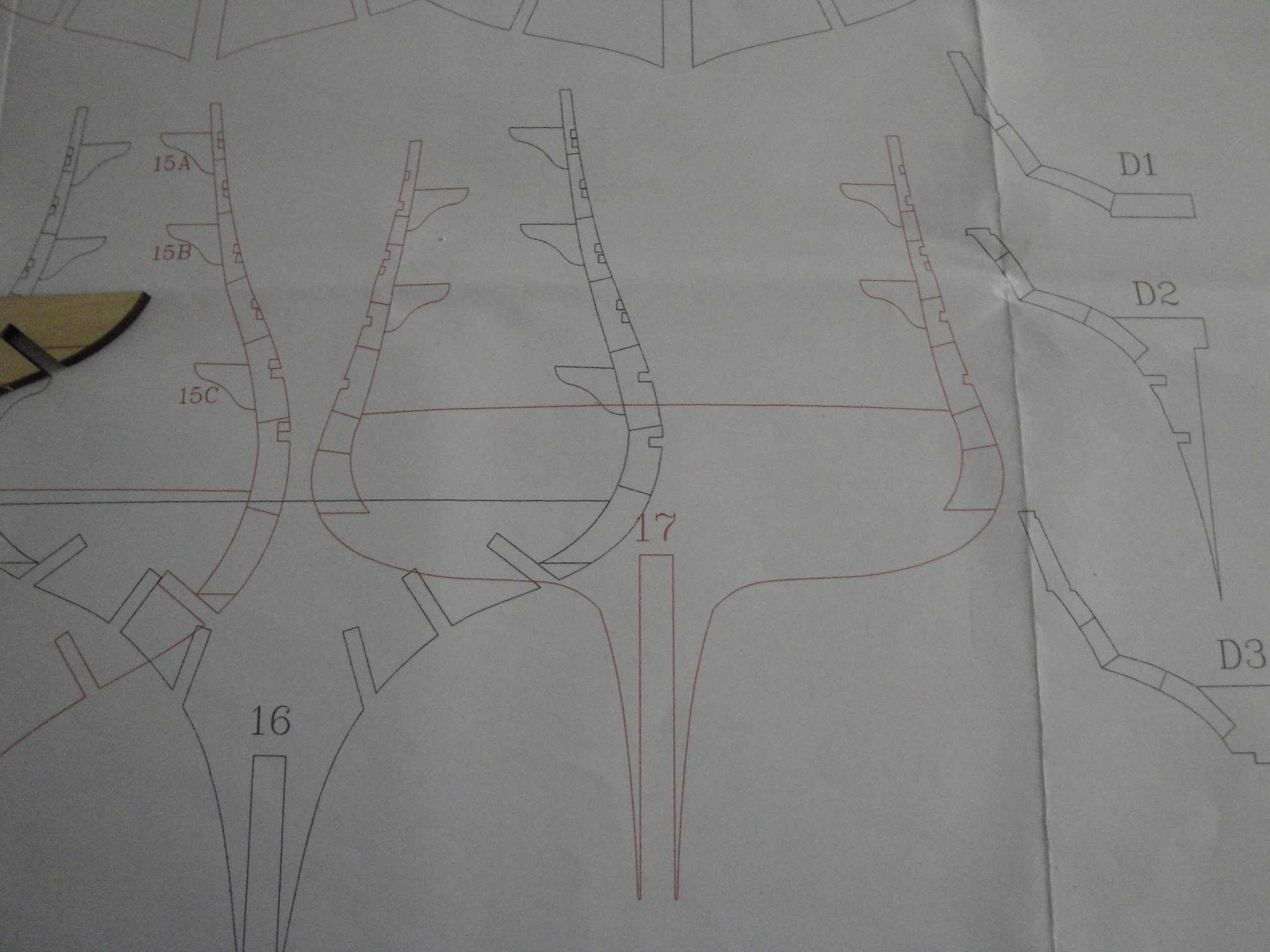
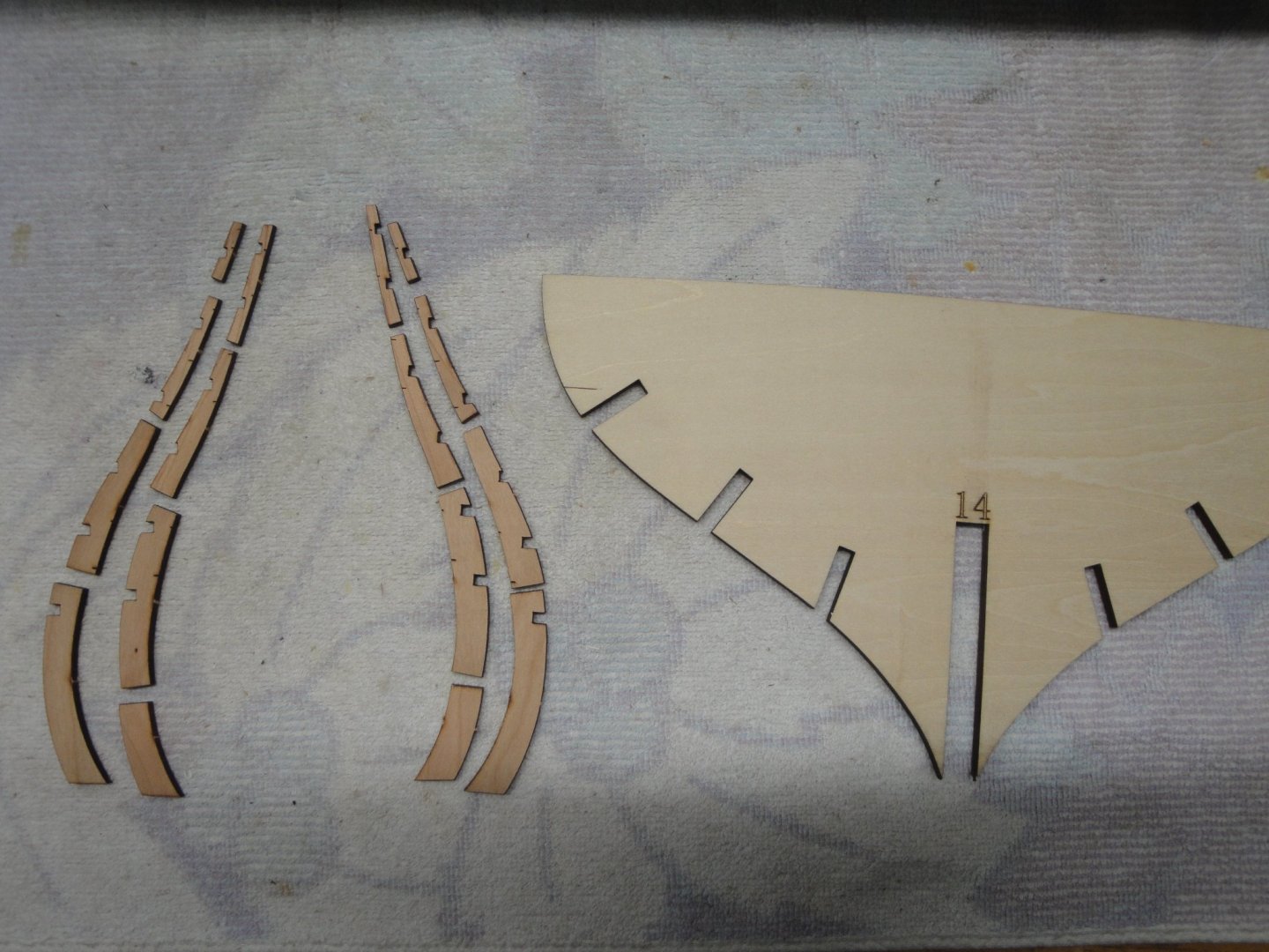
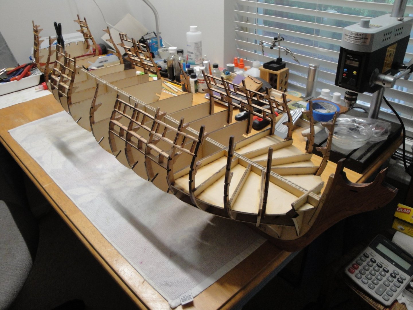
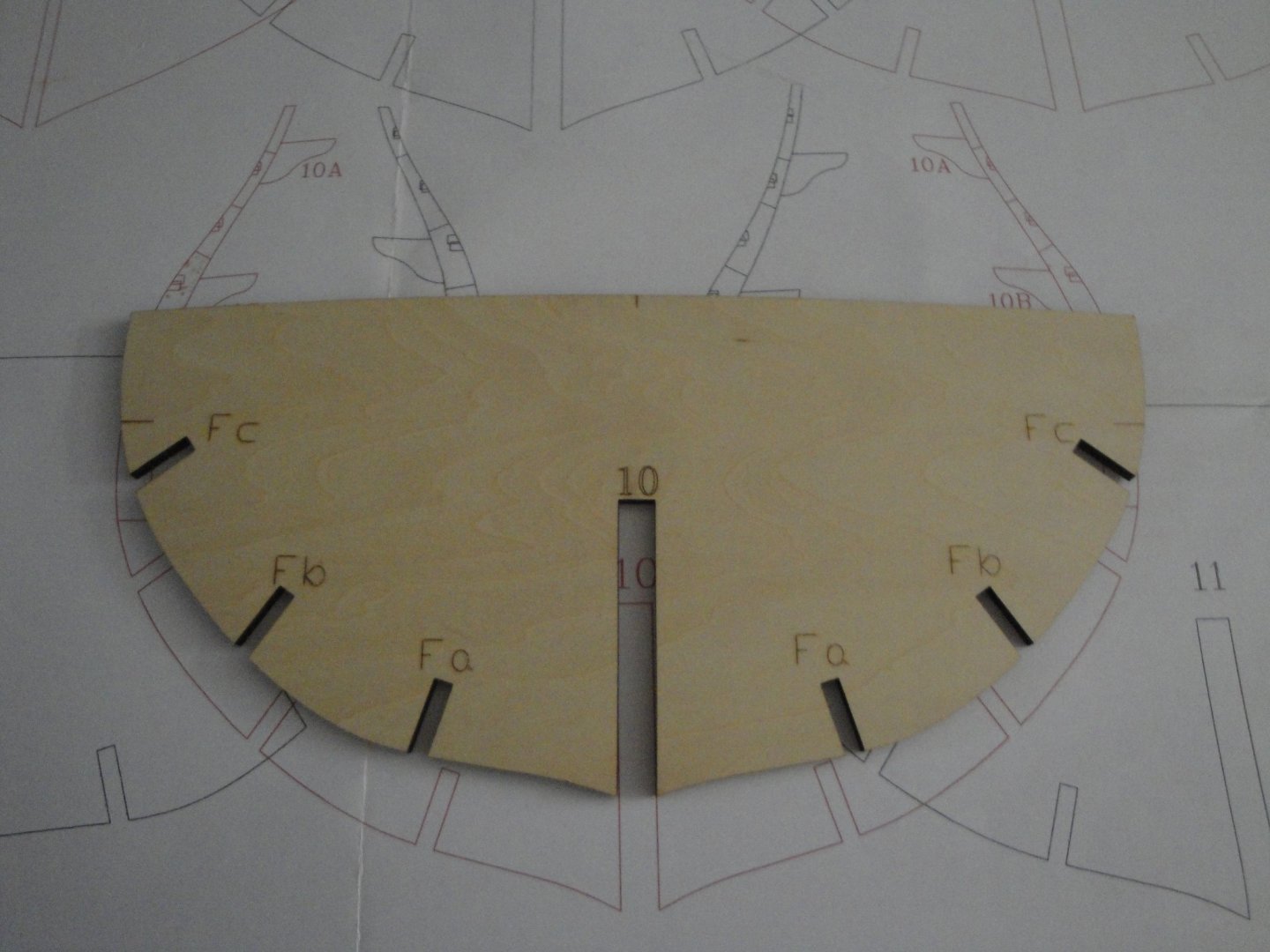
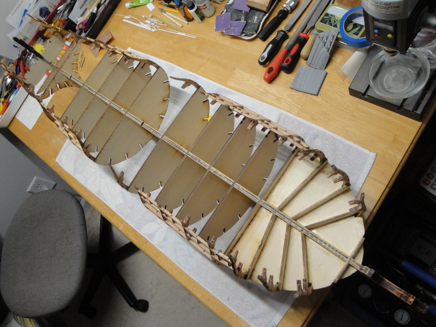
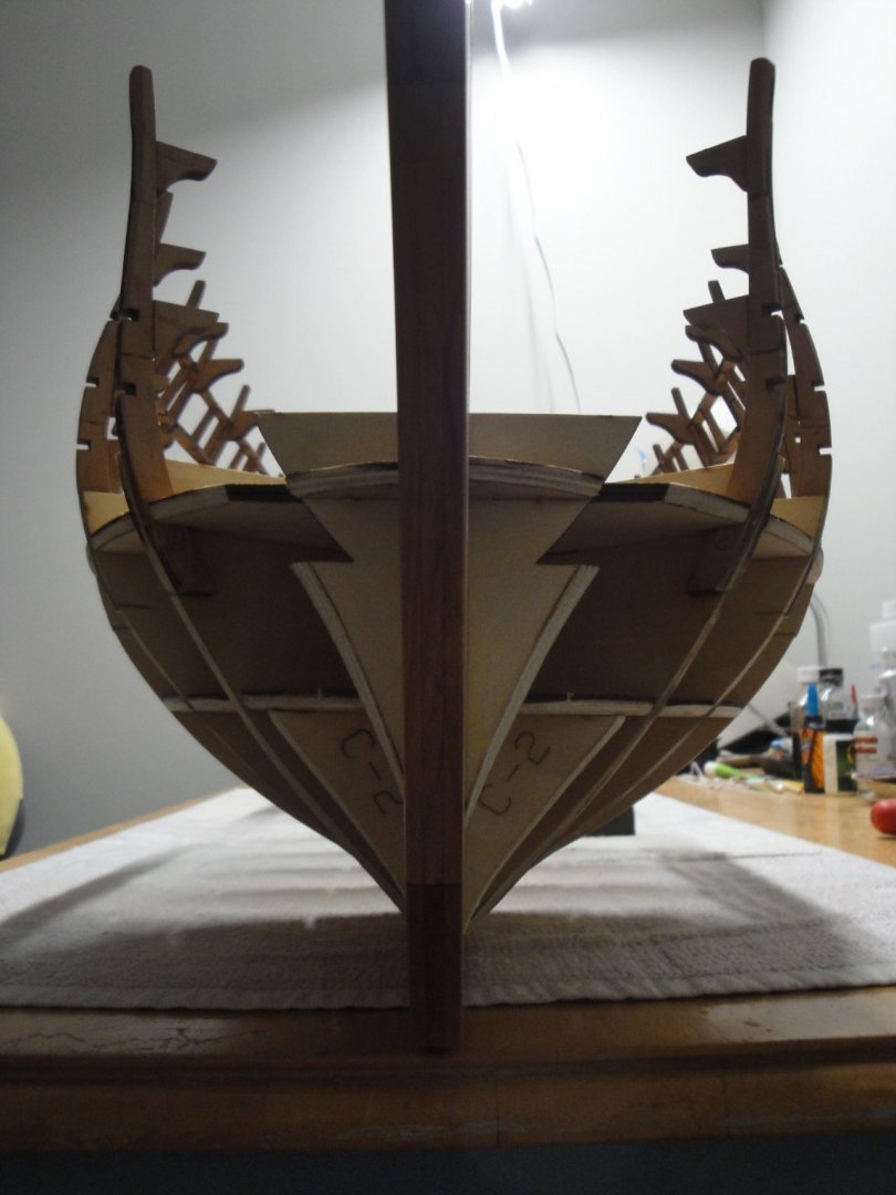
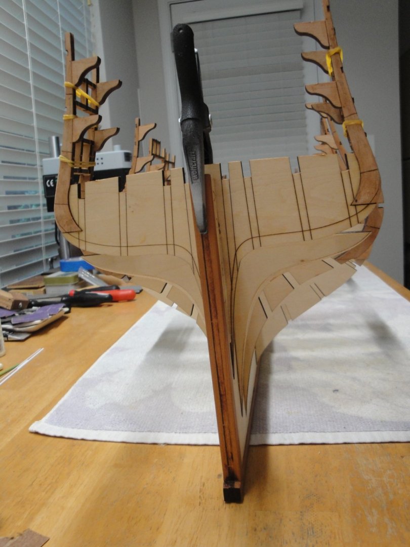
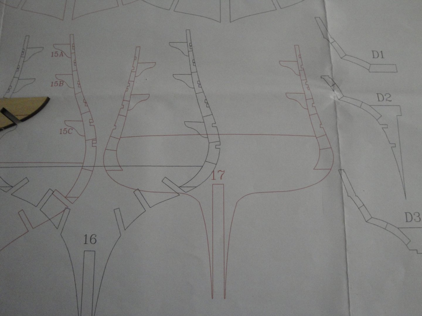
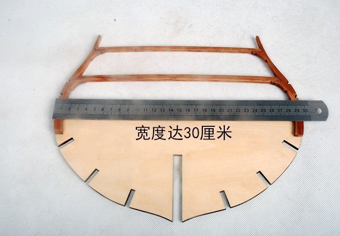
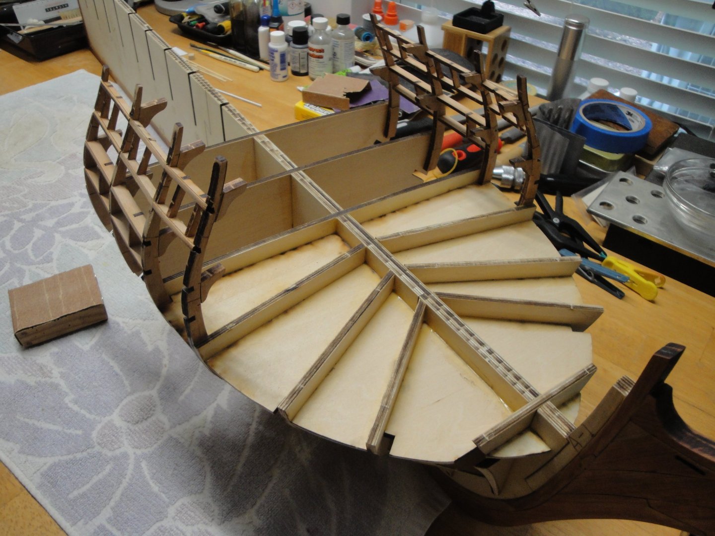
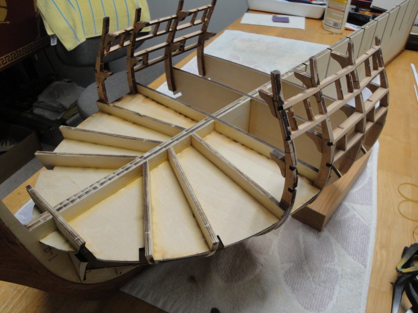
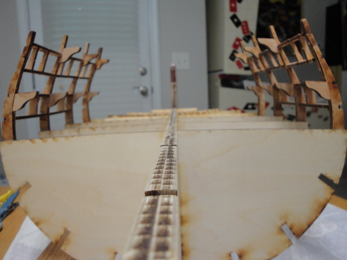
A quick update on the progress of the Bellona Session#1. I have been struggling with a few discrepancies in the kit, but Tom from CAF model has been very quick to respond and very supportive, providing me with all the information I needed to move forward. For people who may want to use that Build Log as a guide in their future endeavor, I will detail the pitfalls I fell into and how to work around them. I am hoping that future versions of the kit will be corrected, when needed. I have been gluing bulkheads up to #9: Those are secured using Titebond Professional Indoor Use, which is very good, quite strong and dries relatively fast (in a few minutes if not using too much glue). The bulkheads are built in the following way. Bulkheads #5 to #8 are done in a certain way, whereas Bulkheads #9 to #18 are done in the reverse way. You really need to be careful, especially for the second rear set, as the slots on the sides of the futtocks, are staggered and glued in reverse from the stem section. Spatial visualization is a must in this case.... Assemble the futtocks (upper sections) carefully. Sand them carefully, glue the deck supports A, B and C in certain cases. Then place the bulkhead on the plan, and glue carefully the futtocks making sure that the alignment is perfect and matching the plan. A slight deviation at the base of the futtocks will cause a very large change of dimension at the top. When dry, glue the assembly on the main spine. As I moved along, I realized that the cross members between the bulkheads were bending them slightly. After checking with Tom, he suggested to assemble in sections and not try to do them all in sequence. Doing so will provide you with perfectly square sections that can be linked later with some minor adjustments. The reason of this, is that the kit is incredibly precise in its cuts and all parts fit perfectly, without any need for sanding or adjusting. When working on Bulkhead #10, I realized that I had a problem there: The piece of plywood does not match the blueprint for #10. All others are spot on. The plywood part is a little too wide 6 mm overall and the bottom of the part does not match the drawing. I dry-fitted it and using a flexible metallic ruler, verified that the curvature of the hull is not affected. It seems to match and align with Bulkheads #9 and #11 and all others. I suspect that the blueprint is wrong (slightly too small) but the plywood part matches the dimensions provided by Tom. So, I will have to be brave and build it. The challenge will be to position the futtocks as the drawing does not match the parts. Below are a few pictures of where the shipyard is sitting as of today: Another issue I found is that the blueprint is mis-labelling Bulkhead #18. It shows as #17 on the plan and in most of the instructions, where in fact it should be labelled #18: Bulkhead #17 is just an ersatz of bulkhead and is there to allow a smoother curve on the stern. Overall, it makes for a very massive and intricate model, with all the numerous cross-members creating the ports for the 74 guns: Assembling this part of the hull requires a lot of concentration to make sure the futtocks/horns are correctly assembled. Their positioning on the main bulkhead is delicate and requires patience and care. I wish that CAF would have provided some kind of wooden templates to make sure that the distance at the top of the futtocks is correct. Below is what I mean.... a piece of wood validating that your assembly is correct.... A discrepancy at this stage will be horrible and I cringe thinking about the installation of the upper decks (Session #3)..... I hope CAF Model will take into account my request and provide for future kits, such guidance for the upper deck and middle deck of the futtocks. I am going to try to finish the main section of the hull as well as the Stern, and then will go back to the Stem. Yves


- 507 replies
-
- 11
-
-
Another little gem, in the building. Yves
-
Very clever way to approach the construction of the dinghy.... Yves
-
Great progress Alan. Yes, I did use two full large cans of primer on the hull. Then three large bottles of Tamiya acrylic paints ( 2 whites and 1 black). That model requires a lot of investments..... Yves
- 460 replies
-
- 6
-
-
- Finished
- Flower-class
- (and 1 more)
-
HO trains and layouts by popeye the sailor
yvesvidal replied to popeye the sailor's topic in Non-ship/categorised builds
The "fading hope" is key here..... Unfortunately. Yves -
These are the little details that count, on a model. Yves
- 127 replies
-
- 1
-
-
- Bowdoin
- Arctic Exploration
- (and 3 more)
-
Lovely boat. Very well rendered and executed. Yves
-
Great pictures and we are all sharing your happiness and elation for taking pictures with the real thing. Not so many models can be placed next to their big brothers or sisters, and you model is a very faithful representation of the prototype. Yves
- 55 replies
-
- 2
-
-
- auguste piccard
- submarine
- (and 2 more)
-
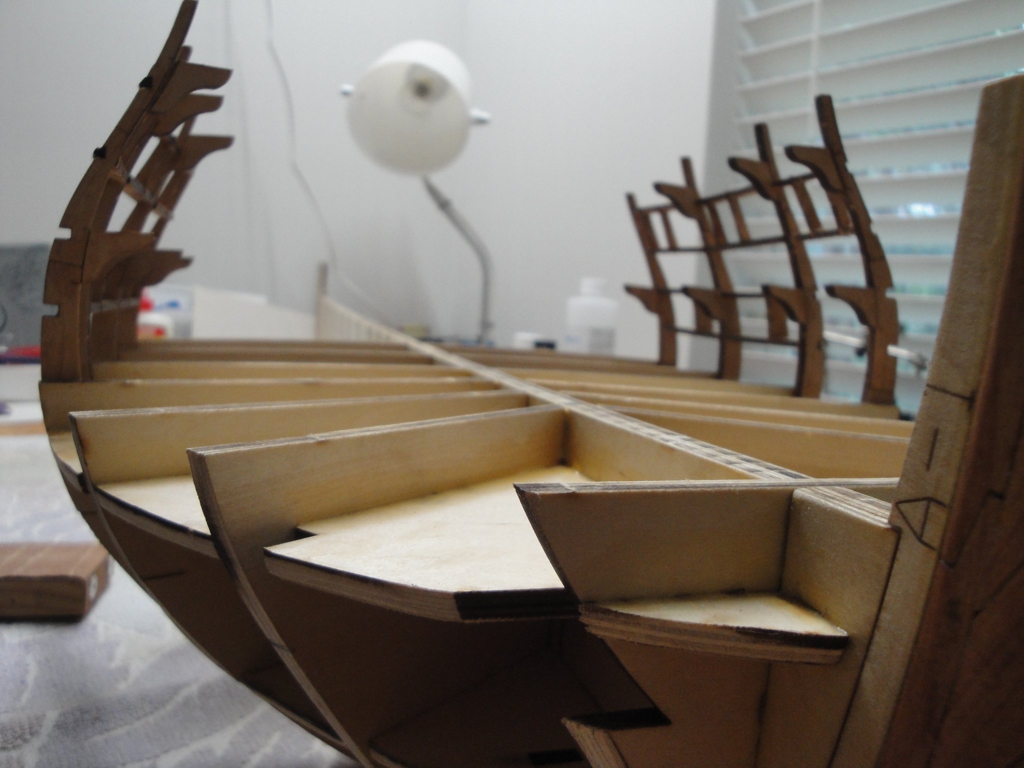
A few progress with the assembly and installation of Bulkheads 4, (5 was already in place), 6 and 7: On the port side, I started smoothing the hull:. All the upper parts are made of cherry wood. For the bulkheads #2 and #3, it is difficult to complete them correctly as I did not glue the extensions using the plan, before installing them on the spine. Fortunately, Tom from CAF Model provided me with the distances between the top of the "horns" for all bulkheads. Before gluing the bulkheads 2, 3 and 4, you should really attach the upper extensions, before installing them against the spine. The documentation is not exactly clear regarding this problem. For Bulkheads 5 to 18, it is easy and you just have to glue the extensions to the main plywood piece using the plan and then glue the completed bulkhead to the spine. For the stem, it is not so easy and the shapes of the Bellona stem are very tortured and unusual. I hope that the deck parts will fit correctly, into that cavernous hull. These are only provided with Session #2 and Session #3. Yves

- 507 replies
-
- 12
-
-
Alan, at least, you are making some great progress. That hull looks great. Depending what you want to do, pay very close attention to the way all the decks are fitting. You can see that the Deck #4 (Galley/Funnel) is being too long and protruding out of the hull. It depends which ship you want to depict of course. I reduced the length of mine by a few millimetres so it would not be too obvious. All this preliminary work will pay off later on. Yes, after some primer on the hull, you will have a better picture of what needs to be corrected. I used two cans of primer, with putty in between. For the warping, make sure you stay at 60 degrees for the bed. No more no less. Yves
- 460 replies
-
- 5
-
-
- Finished
- Flower-class
- (and 1 more)
-
A nerves wracking operation..... You did well. Yves
-
Incredible work on that great kit and boat. Yves
-
Great picture !! Modern art ? Remains of some prehistoric creature? I love it. Yves
-
Incredible work Neil. Yes, there is no substitute currently, for a resin printer. Yves