


SJSoane
-
Posts
1,620 -
Joined
-
Last visited
Content Type
Profiles
Forums
Gallery
Events
Posts posted by SJSoane
-
-
Hi Allan,
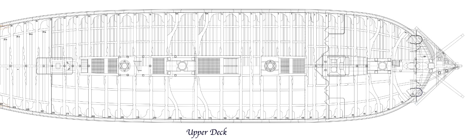
In passing these on to you, I noticed something I had not seen before. Directly afore the ladder from the quarterdeck down to the upper deck, there is a pillar on the center line right at the base of the ladder. It also required an additional carling on the centerline, which seems like redundant structure with the two carlings either side of the ladderway nearby:


And then I see again the same situation at the ladder from the upper deck to the gundeck, a pillar directly at the base of the ladder:
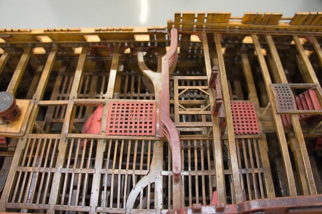
It would have been so easy to put pillars on the carlings either side of the ladder way, not blocking the access to the ladder. So there are other considerations going on, whether pillars are on the centerline or not. Just when you think you understand what those guys were doing!
BTW, I use your Scantlings book quite regularly. Great book!
Mark
-
Hi Allan,
I wrote to the National Maritime Museum in 2011, and asked if I could visit the Bellona model. I showed them the work I had done on my research and model. They arranged for a private viewing in one of their back workrooms, and I was allowed to take as many photos as I wanted. They hovered in the background working on something else, but I really was left to look it over. I was so, so, tempted to touch it, just to say I had, but I honored the conservator's golden rule of not touching.
I was also given permission to show these photos on our website, as long as I or anyone else did not use them for personal profit.
I visited Chatham in mid winter, and so all of the galleries were closed to visitors back in 2011. I didn't see anything but the Bellona model. Maybe someday I can get back and go through the galleries!
Great memories!
Mark
-
-
Hi Allan,
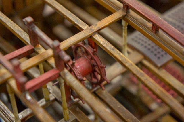
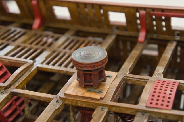
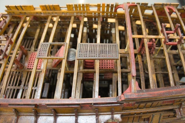
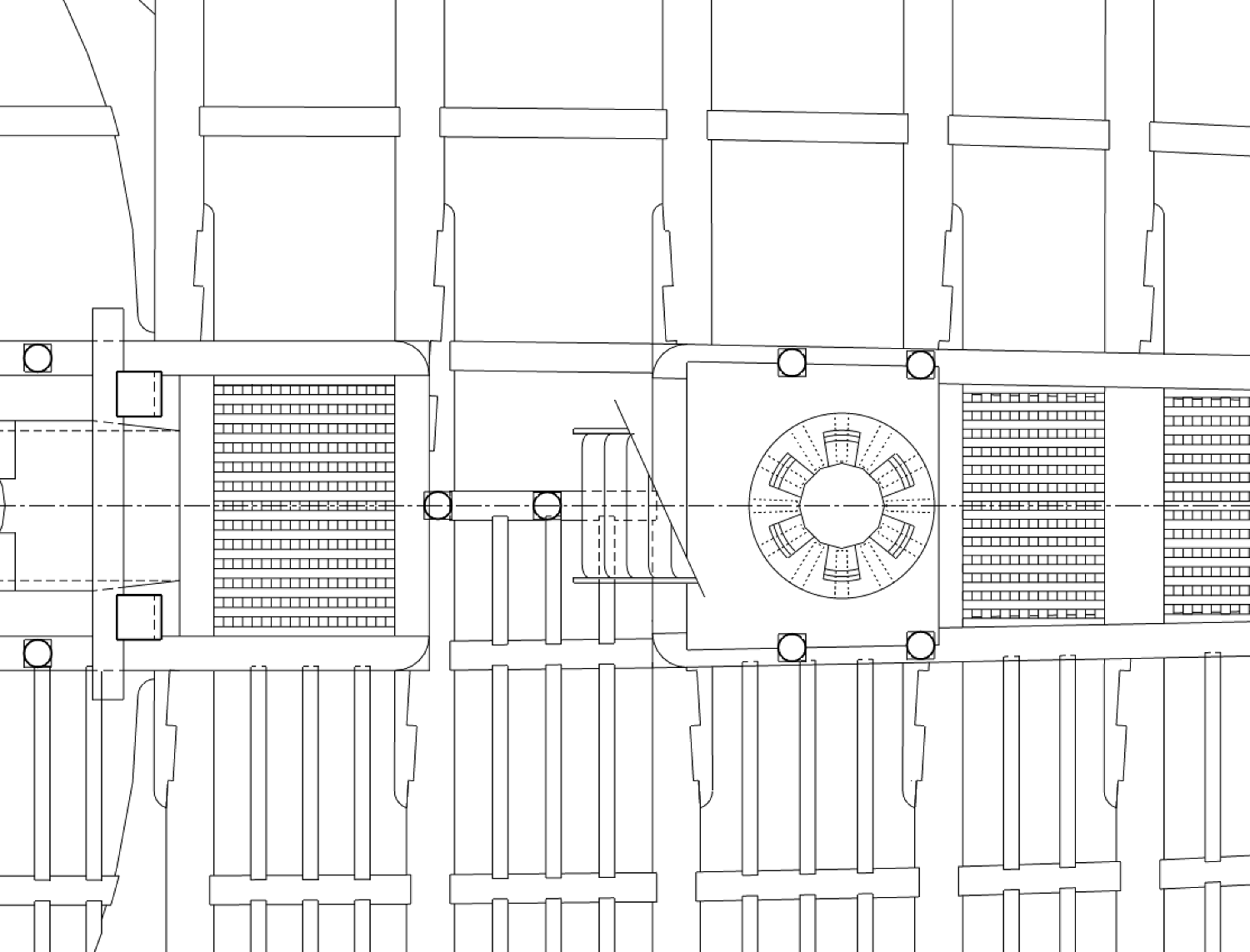
Peering down into the first model of the Bellona (74) 1760, I saw mostly pillars down the center, but in a few places there are two beside each other. They double up at the wheel, as you see below, at the capstans, at some partners. There seems to be some practical reason for the switch, adapting to particular circumstances in a particular location. At the wheel, it is to line up with the bitts; at the capstan it is to find clearance in a tight spot behind a ladder.
I found it helpful to draw the pillars on the deck plans overlaid with each other, so I could see where the tops and bottoms of the pillars would hit. Then I could see why the shipwright (or at least, the Bellona model builder) made adjustments to the general rule of one row down the center.
Just one more piece of information to add to your design challenge!
Best wishes,
Mark
-
-
Thanks so much, Gary, Marc and druxey, for your kind thoughts. Gary, I have sent you a PM about drawings. Marc, like you, I love working through problems and finding solutions. I am glad you find mine interesting, because I enjoy looking over your solutions to historic accuracy.
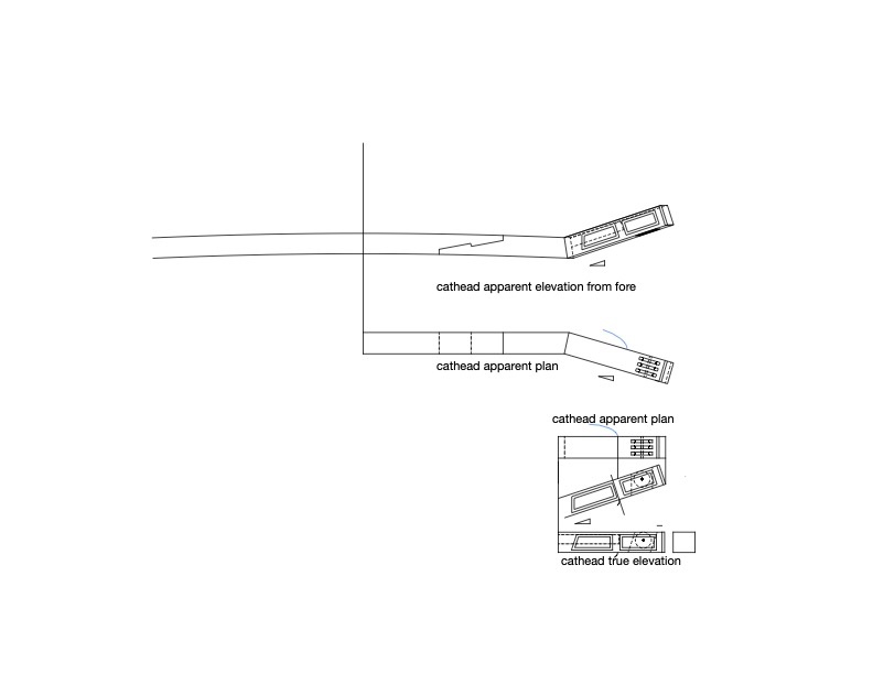
And druxey, as you know, the projection drawings on the catheads are particularly fun, since they have to be adjusted first from true elevation to apparent plan, and then from the apparent plan to an apparent elevation to account for the stive in two directions. I confess it took me a few tries before I could visualize what was going on. I tried at first to work this in one step rather than two, but it was too complex for my poor imagination. I guess one step at a time keeps things more orderly!
Here is the cat beam fitted but not yet installed. Facing the prospect of many more beams to install on 3 more decks, I decided to rationalize the work a little.
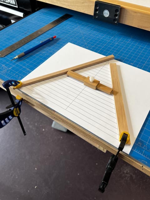
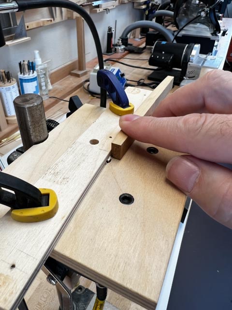
I use my sliding jig to measure the distance at each beam between the sides. The next challenge is to trim each end equally so the centerline remains on center. I made a simple jig seen here, in which I can position the sliding measuring jig between converging strips of wood, and mark the location on the paper.
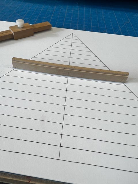
Removing the side strips of wood, I can then align the center line of the beam with the centerline of the jig, showing me exactly how much to trim on each end to remain symmetrical:
The cat beam interacts with the complex reverse tumblehome at the bow, and so its top surface aligns at an angle less obtuse than the lower surface. I used angle gauges to determine the top angle, and then progressively filed the lower surface through trial and error.
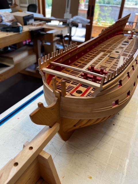
So now the first transverse piece at the bow, which will serve as the foundation for the entire beakhead bulkhead. It was very gratifying to see that the hull form I had constructed so many years ago aligned perfectly with where it needed to be in order for the cat beam to fit properly.
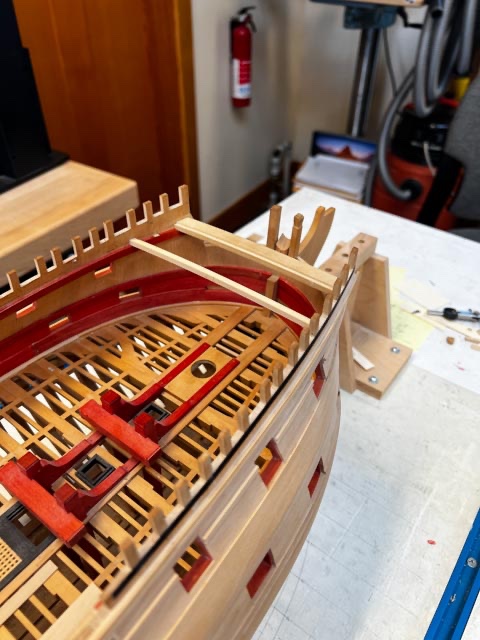
Next, thinking about the catheads and how they will cut through the bulwarks. I wish I had thought about this before already installing the sheer trim that will be cut into at the base of the cathead. Some precision surgery needed to keep this intersection clean.
Mark
Mark
-
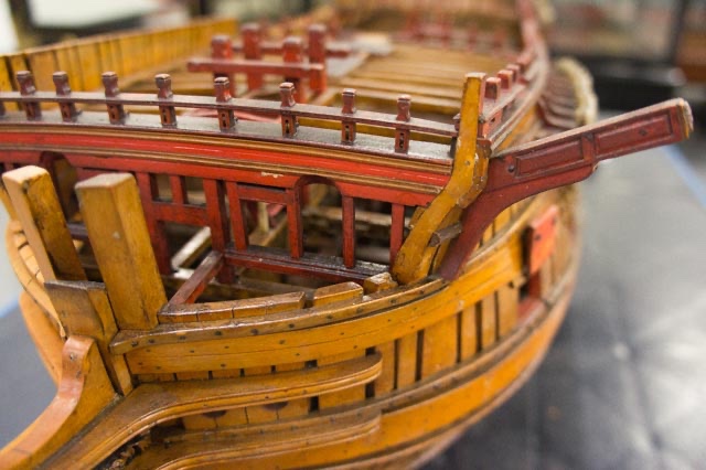
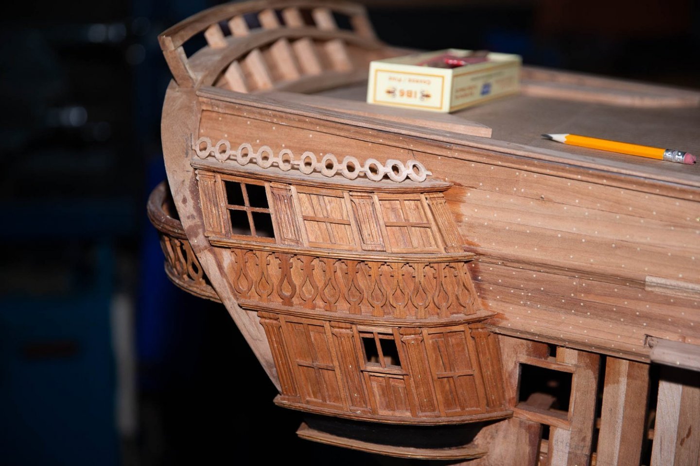
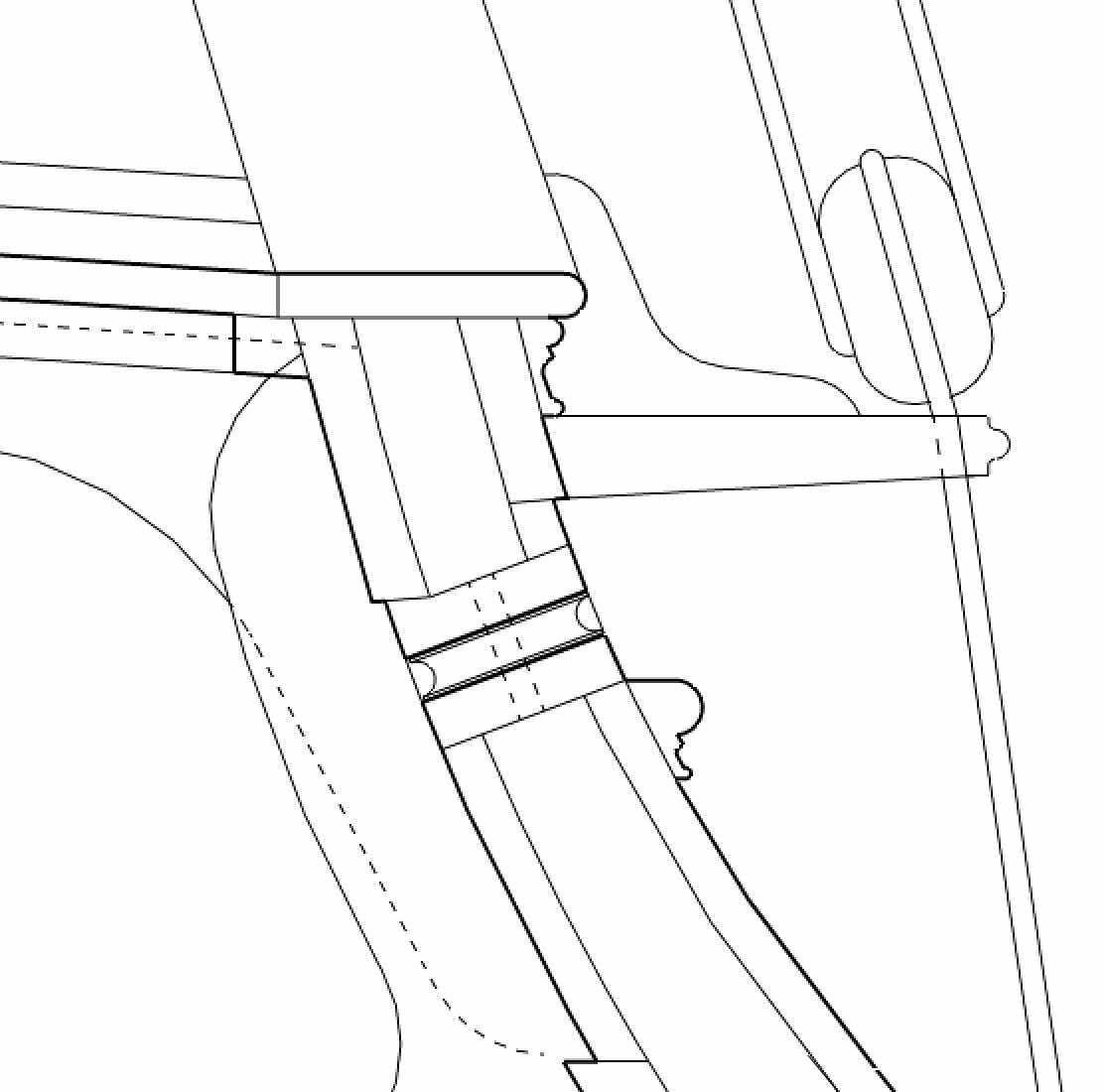
While attending to the cat beam, I had to look again at my reconstruction of the beakhead in the original model. I saw more this time than I had seen before. Notice the arches over the doors to the fore platform. At first, I though it was cut through the cat beam with a half circle on the fore side, and an elliptical shape on the aft side. But after messing around, I realized that it is an additional baulk of wood afore the cat beam, through which is cut an arch in elevation and plan, or a quarter dome. You can see that in the section below. I imagine this was done to give more headroom for the door, while minimizing the wood cut away from the lower surface of the cat beam.
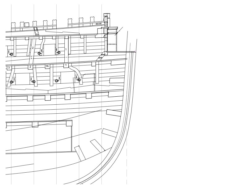

I also realized that the original sheer drawing from the admiralty grossly mis-represented the cathead. The contract for the Marlborough, built just 2 years after the Bellona, gives information on the cathead with a "steve" (stive) forward of 3 1/2" to the foot, and upward of 4" to the foot. The Berwick and Bombay contract gives a length of 7 feet outboard. I drew some apparent size drawings for plan and elevation using this information, and came up with a more compact new of the cathead in the sheer drawing. Here is the geometrical construction of the cathead in plan and section:
Here is the original admiralty drawing:
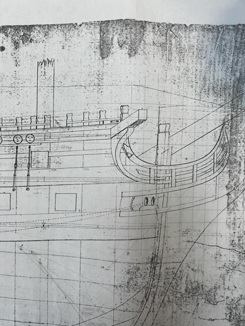
and here is my more accurate rendition:
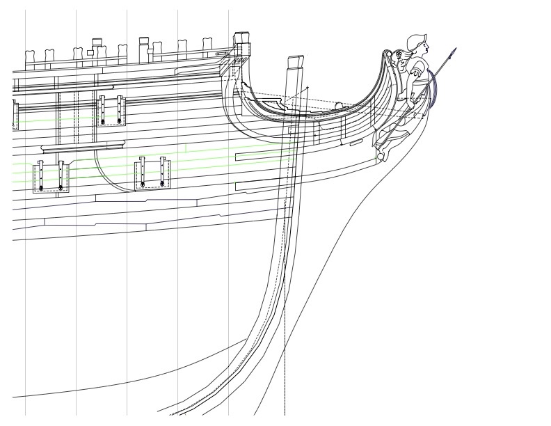
For so many years, I had assumed that the Admiralty drawings were the most accurate information I had, and I could trust its dimensions. I now realize that it followed some drafting conventions that simplify and distort, like the upper head rail drawn as if it were parallel to the drawing plane, not angled towards the figurehead. Multiple sources of information usually save the day!
Mark
-
I am still working away, slowly. I have run into a continuing puzzle of what happens before what in the building sequence. I know I have to finish all outboard work and paint and work the friezes, before fastening the guns in the gundeck (because they stick out) and proceeding along to the upper decks. However, I can't finish the outboard works before fitting the cat beam and cattails. So now I have to flip back to decks for a time. Maybe I will start the remaining decks at the bow, finish the outboard work, paint, and then get back to the decks...
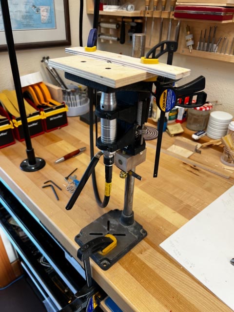
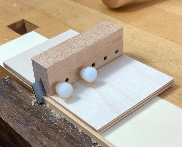
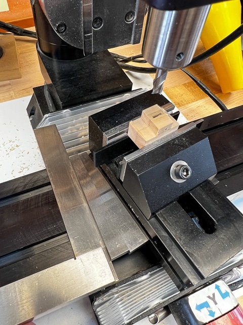
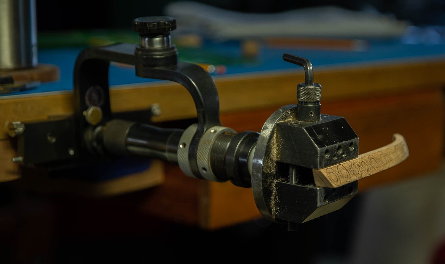
Long story short, I have started on the cat beam. It requires a rabbet at its aft side, for landing the planks of the quarterdeck. I have long thought how nice it would be to have a small router table, and now I need one. I suddenly thought, what about the Foredom drill press stand turned outside down? it worked!
I made a fence with a face the same radius as the top of the beam, which provides good support. A wooden block fitted below the Foredom clamp allows a screw for fine vertical adjustments.
I saved a bunch of money on a dedicated miniature router table; I wonder what I should spend it on?🤨
Mark
- Wintergreen, GrandpaPhil, egkb and 12 others
-
 13
13
-
 2
2
-
Thanks so much, Marc, Gary, Mark and druxey. I am really looking forward to doing something else besides planking!
I learned a lot in this planking process. I remember reading Longridge's Anatomy of Nelson's Ships many years ago, where he described mass producing identical planks on a jig. At first thought, this should work because the sheer and planking lines on this hull as drawn in the sheer plan are arcs of circles; therefore, you would think that the planks would be parallel sided with a constant radius, and the same all along the hull.
But this is not the case. The tumblehome bulges more at the midships than the extremities, and the aft upper works are flatter than the strong curves at the bow. This creates a sinuous flow of strakes, getting wider and narrower as they progress along the hull. It is a visual delight when completed, but it means that every single plank needs to be spiled to its specific location. I don't know how Longridge ever made his identical planks work.
Also, this means that while the lines are perfect arcs of circles as seen from straight on in the sheer drawing, the actual curve on the face of the hull is not a perfect arc. The radius of any given strake changes as it progresses along the hull.
I learned how to spile from David Antscherl's and Chuck Passaro's excellent articles posted on this Model Ship World website.
And once into the game of spiling each plank, I experimented with a number of ways of turning these out efficiently. I tried a jig to hold planks on edge for planing, but never satisfactorily planed the concave edge despite investing in small planes meant to do this. Next, I tried cutting each plank out of a sheet with a jewelry saw, and then filing the edges smooth, which worked but was very slow. Also, the curves of adjacent planks did not always align perfectly.
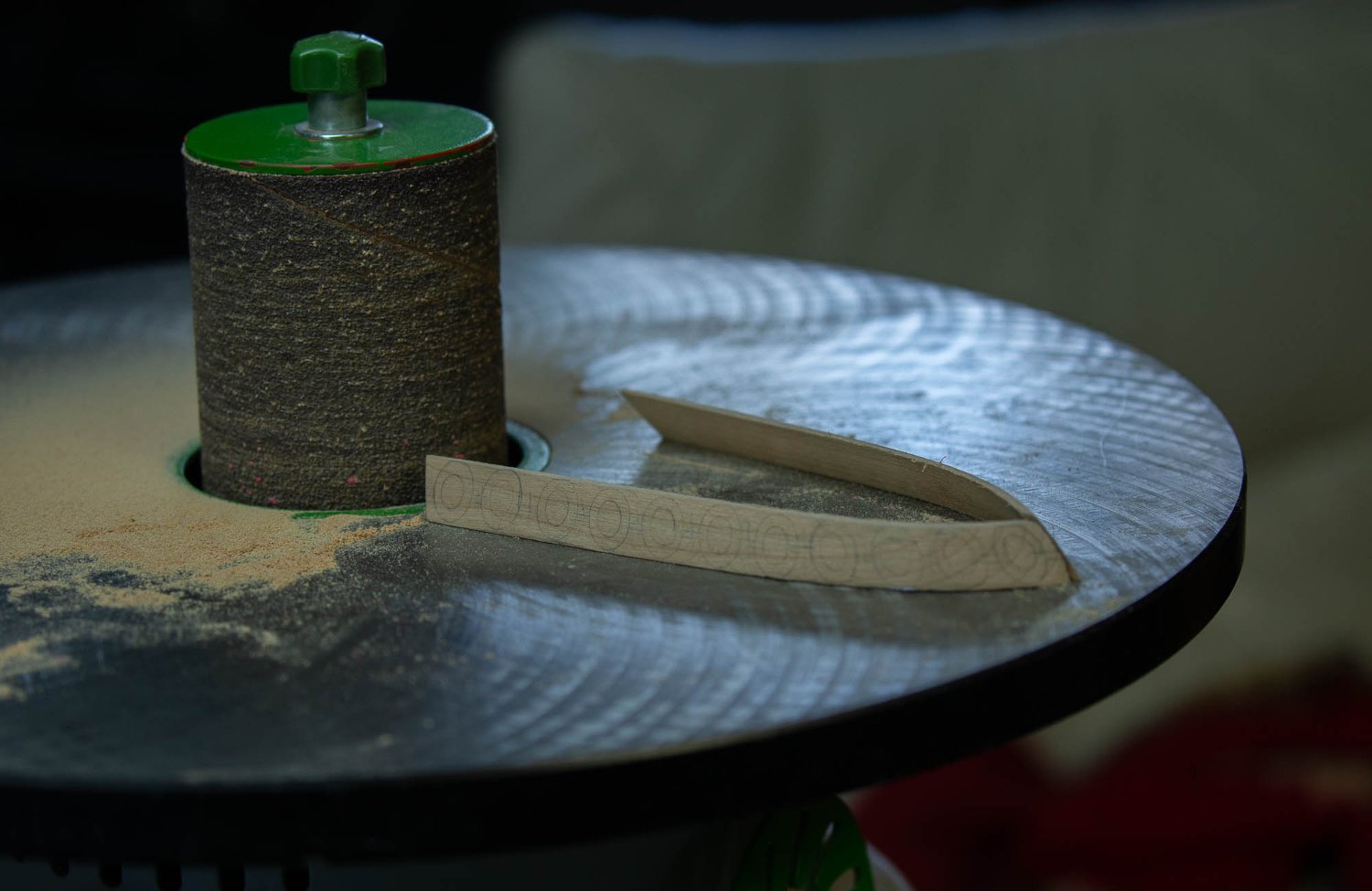
Finally, I ripped strips of wood wide enough for the widest plank in a strake, then shaped each edge with long concave and convex sanding blocks. I make these by laying out the radius I want using a plastic template from a set of road-drafting curves I was given years ago. I bandsaw to the line, then put coarse sandpaper on one edge. I rub the two together back and forth to smooth the face of one block, then reverse the sandpaper to sand the other block. They are perfect curves.
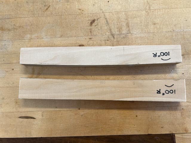
I attach sticky backed sandpaper, and then clamp the sanding block in my workbench. I rub the plank against it, rather than trying to hold the block and plank in my hands. This gives much more control and consistency in shaping the edge:
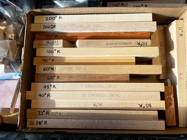
I have accumulated enough blocks of different radii to meet every spiling and shaping need on my hull.
I usually had to bevel the lower edge of each plank on my upper hull, due to the tumblehome. I would rub the plank along the sanding block at a slight angle to get the desired bevel. This of course changes the radius a bit, so I learned over time how to exert pressure at the ends or the middle to adjust the radius slightly back to what I need. Checking its fit periodically against the lower plank would tell me when I had a perfect fit. After spiling the width of the plank at various points and drawing a smooth line through the points, I then chose a sanding block of the correct radius to form the upper concave plank edge.
Once the planks in a strake are glued on, I run a sanding block of the desired radius along the top edge. As mentioned above, the radius at the top of a complete strake varies along the length of the hull, so I use the appropriate radius block at any given point, and smooth the transitions between radii to get a fair curve along the entire length.
Where the ends of the planks had to be cut for a gunport, I would hold the plank to the hull and draw the angle needed for the cut. I would adjust my Byrnes disk sander to sand this angle, then test it against the hull for parallelness to the gunport edge. I would judge if it needed to be a sharper or shallower angle, adjust the miter gauge on the disk sander, and try again. It often took me three or four tries before the angle was perfect. Using the miter gauge meant that I could sneak up on exactly the right angle by slight adjustments to the gauge.
The other discovery that really helped was to clamp planks down onto the plank below, as well as against the hull. My dockyard style hull helped enormously for this, because I could put a clamp jaw below the wide lower edge of main wale, and then the other jaw on the plank to be clamped. This really helped pull things together snuggly.
Having finally perfected my planking techniques, my planking days are soon coming to an end. At the rate I am completing the Bellona, I will never be planking a ship model again! Maybe I need to bequeath my collection of sanding blocks to someone when I finish the Bellona.....
Best wishes,
Mark
-
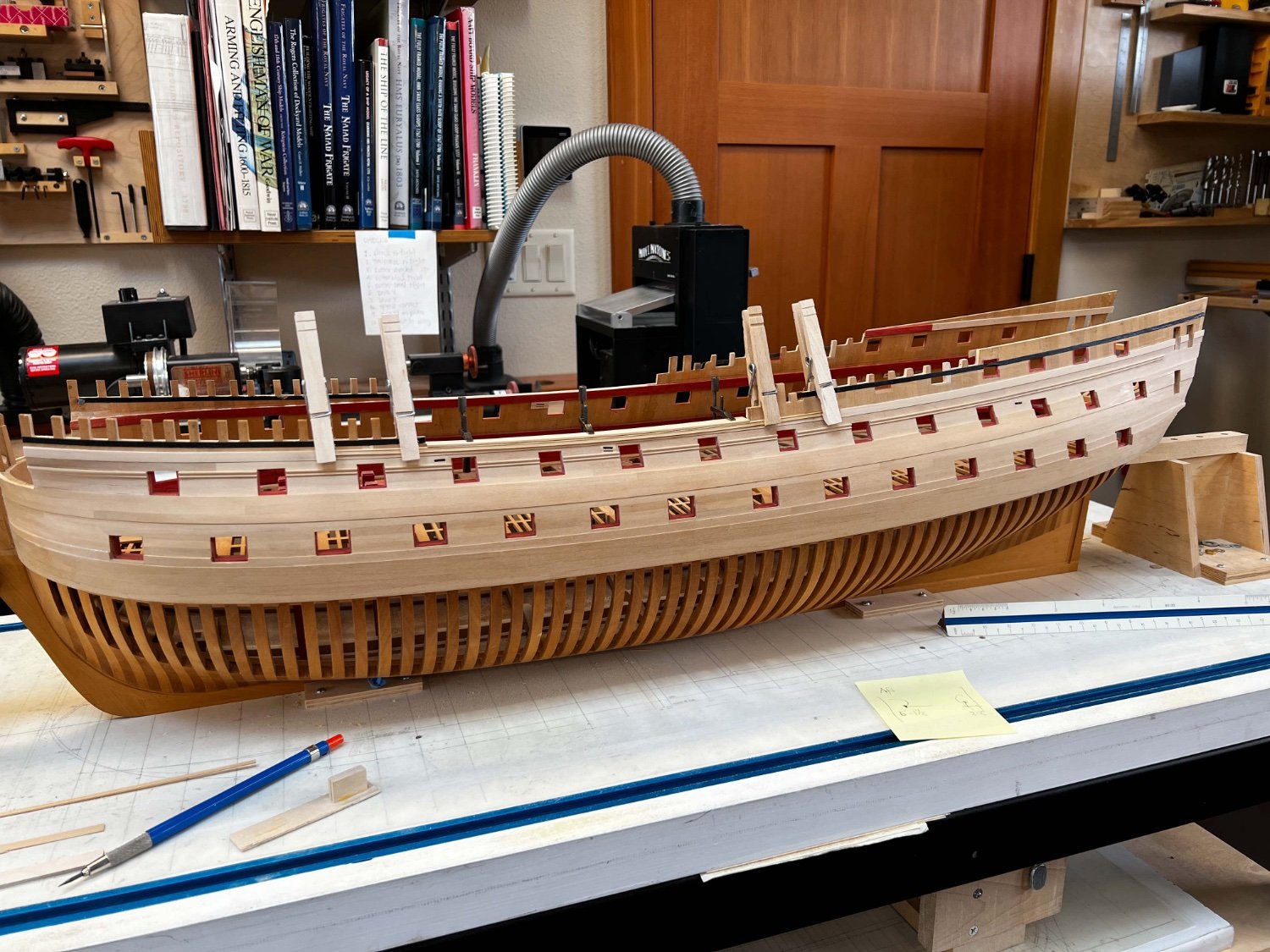
Slow but steady progress. I have planked up to the drift rail level, and look forward to cutting those volutes in the drift rail. I started this outboard planking 5 years ago to the day, and this is what I have to show for it. In this period I did cast the guns and prefabricate the beams for the remaining decks, but still slow, slow, slow!
My wife is threatening to put my ashes on this ship and push it out into the lake on fire, if I don't get it done before I pass away. So I am highly motivated to keep going....
Mark


-
Hi druxey,
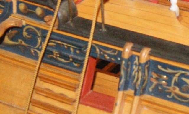
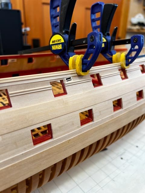
I have gone back and forth, back and forth, on this question. I thought about the paper, and then looked in more detail at a number of slight changes in surface that I would have to deal with. In particular, the lower edge of the sheer strake is offset slightly from the planking below. You can see that very clearly in the first photo below, the offset just below the moulding currently temporarily clamped on. Bending one sheet of paper around this would kill the sharpness of the detail, and a sheet on each surface would leave an uncovered lower edge of the sheer strake.
Also, as in the second photo below, there are a number of pieces that the painting wraps around. I could paint these separately, but wondered if I could match the same color and transparency on the paper versus the wood parts painted.
To be honest, trying to think this all through has slightly incapacitated my further progress. I know what I need to do is try a couple of experiments off the ship. I should try painting on paper and attaching to dummy bulwarks; and then also spray painting and painting the frieze directly on wood.
You have nicely prompted me to this action. Once I get the mouldings attached, I will proceed with some experiments!
In your Comet example, did you glue the paper to the final surface, and then trim with a scalpel to the required edges? or trim it first, then glue? Getting a clean line to the lower edge of the sheer rail is what I find daunting in this, since this will be so prominent.
Best wishes,
Mark

-
Hi everyone,
It has been a long time since my last post. Other things going on, slow progress on the Bellona with little to show of interest. A lot of thinking about next steps!
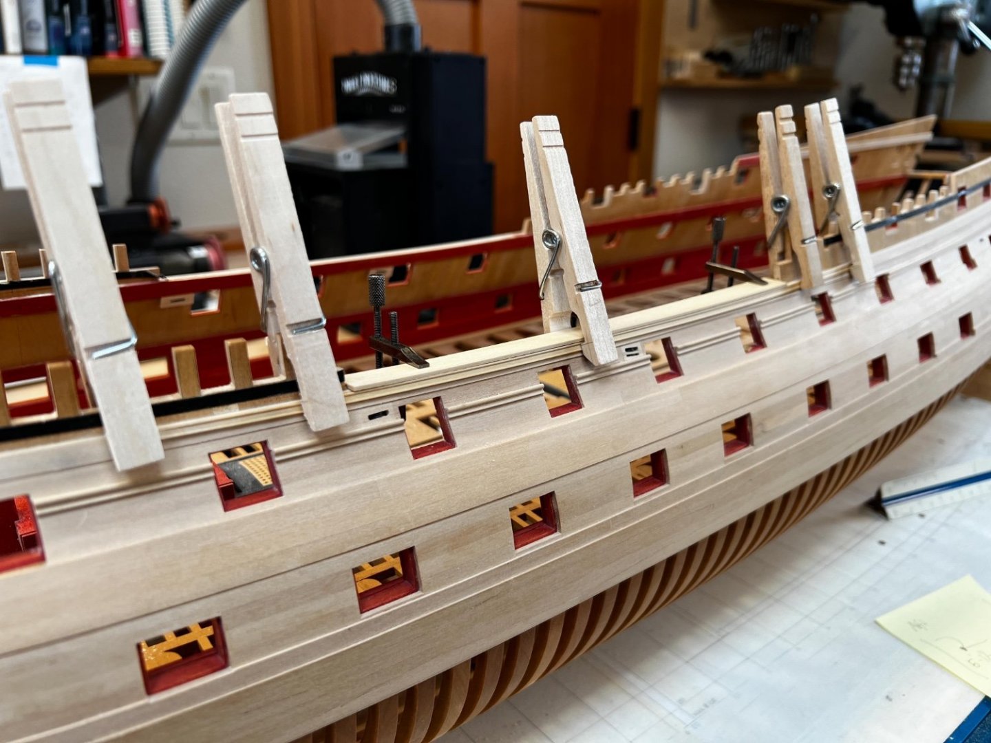
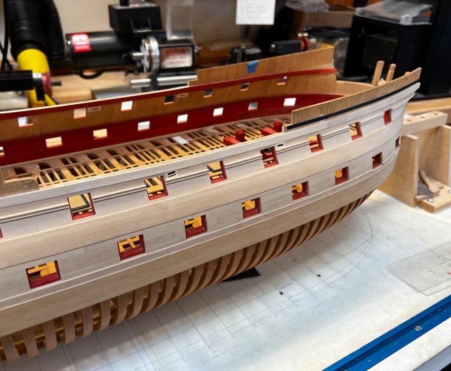
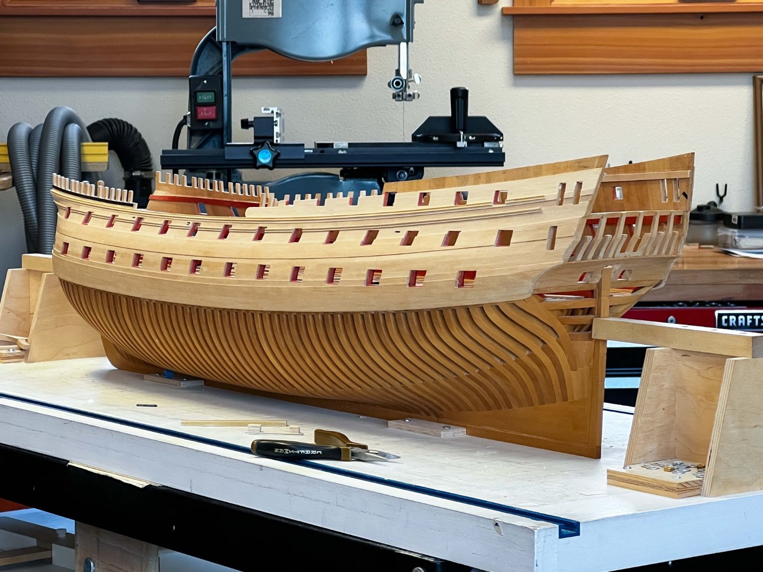
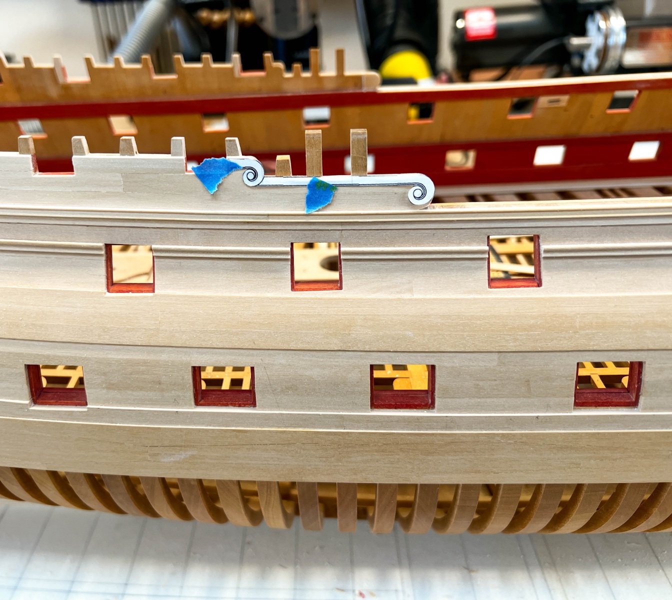
I have finally roughed out the timber ends, giving the hull a much lighter feeling. These still need their distinctive hollowed top and sides. And they bring into play the railings at the their base and halfway up their lengths. I am still thinking how to do this, likely inserting short pieces between the timber heads, and then continuous railings alongside to give the appearance of a railing pierced by the timber heads.
I have completed the sheer strake, which was particularly satisfying since it really contributes to the sweet lines of the hull. I am now beginning to fit the moulding over the sheer strake. This will be very obvious in the final model, and it needs a particularly smooth, faired line. I have made a ply template at the right curvature, that I will clamp to the hull above the moulding and then clamp the moulding up to the lower edge of the template when glued. But in the waist, the fairness will be particularly obvious, and the ply template doesn't have anything to rest on or clamp against. So I decided to start fitting the capping rail in the waist, up to which I can clamp the moulding for a smooth run when I glue it.
The lower photo shows a temporary rough blank for the capping rail, to check the fairness in both directions. I'm thinking I will glue the mouldings first, then come back and do the capping rail. This gives me a final edge against which to test the fairness of the outer edge of the capping rail.
I got into a whirlwind of thinking, trying to figure out the sequence of painting and assembly in the upper works. Everything above the waist rail already installed is painted a dark blue for the frieze, except for the sheer and drift rail mouldings which remain bright, and the top rails and timber heads which are black. I have decided to spray paint the blue, after masking the mouldings to which I have already applied the polyurethane finish. We will see!
BTW, I just received the NRG thickness guide for the Byrnes saw. Beautiful, works well. Thanks everyone who made this possible!
Mark

-
On 4/2/2022 at 9:34 AM, Gaetan Bordeleau said:
1 more photo

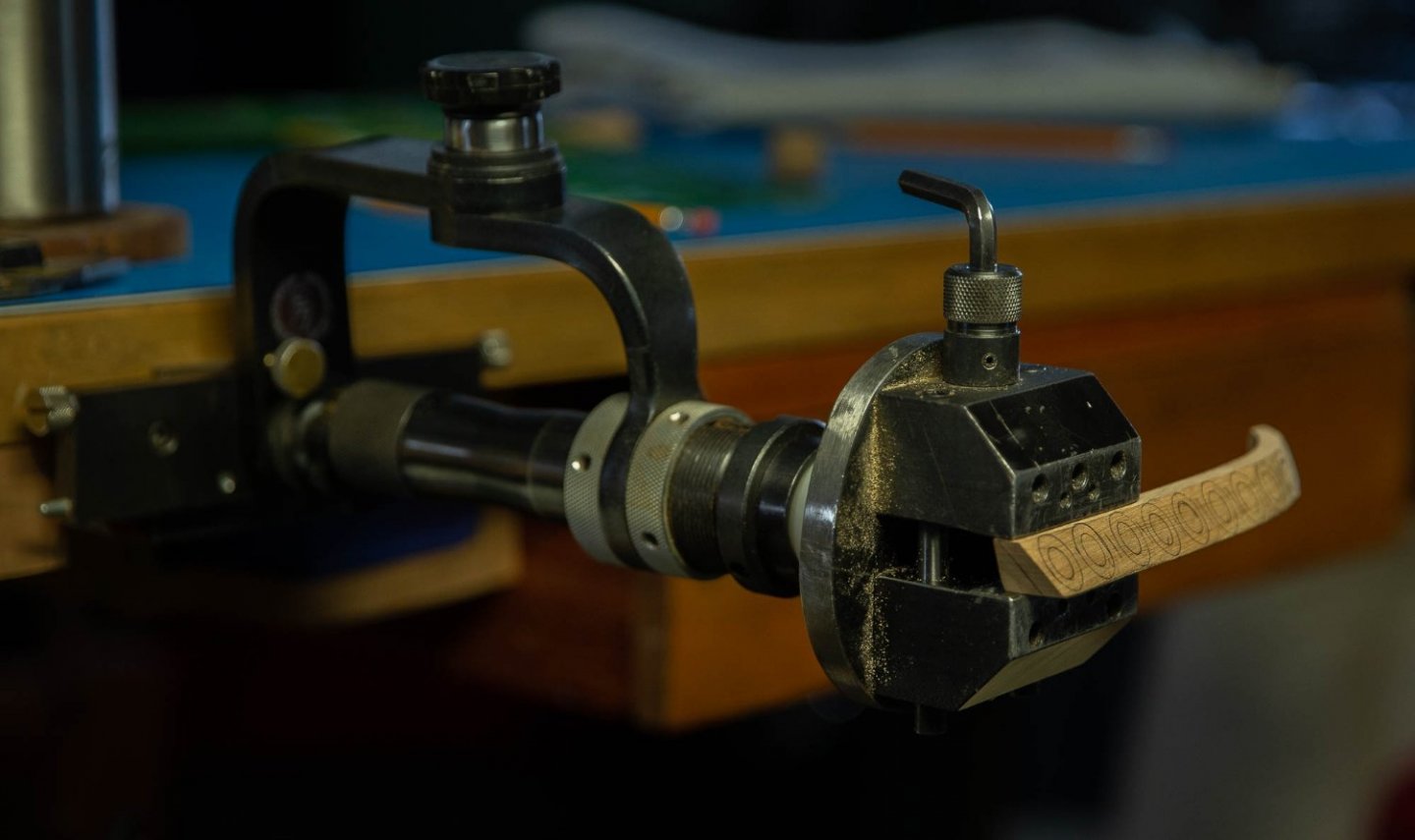
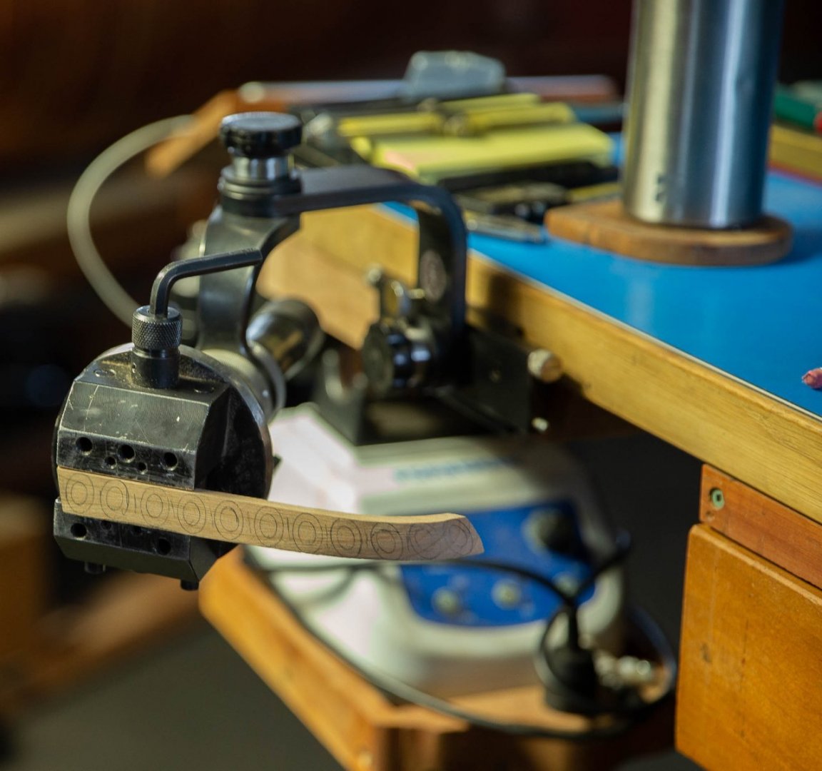

Hi Gaetan,
What is the vise setup you are showing here? It looks like a GRS vise itself, but is that also a GRS adjustable arm? I don't recall seeing anything like that on their website, that would hold their vise.
The ship is looking great, by the way. Beautiful carvings and details on the side galleries!
Your work continues to be an inspiration.
Mark
-
10 minutes ago, AON said:
What about using these replacement erasers on the end of a dowel?
Integra Pencil Cap Eraser for Standard Pencils, 144 per Box, Pink (ITA36523)
Clever, clever!
I remember these from when I was a kid. Nice find, thanks!
-
Thanks, Mark, good warning. The virtue of the pencil is the non-slip eraser end. Any ideas on another way to get a grippy end ? Maybe coarse sandpaper on the end of a thicker push stick?
-
-
Gaetan, I looked up the species name you gave me, and discovered that this wood is described as "very resistant to flexing", which might explain why I have found this to be so challenging when steaming and bending. Thanks for the information!
druxey, I will try a piece using your method, and the cutter I already made. I'll see what happens.
Bruce, I cut with the moulding face against the fence to ensure that the piece would be a uniform thickness. The scraping process sometimes seemed to end up cutting things at a slight slant relative to the original face, and therefore at a slant to the face at the opposite side of the blank. Running the blank through with the finished part on the side opposite the fence would have resulted in a moulding thinner at one end than the other.
I always work with a blank wide enough to keep my fingers well away from the blade, using a pencil with a rubber eraser as a push stick. I hold the push stick very close to the blade so the thin piece never has a chance to ride up on the saw blade, and I push in short moves so I can reposition the pencil often. I am super aware of possible kickback with a thin piece trapped between the fence and the blade, and I stand to the side and wear a full face shield. But keeping the wood firmly down on the table and against the fence with the eraser tipped pencil seems to keep everything tame. So far.
Alan, I also use a blank of the thickness I desire to set the fence to the blade, although this still needs some adjustment after trial cuts are made.
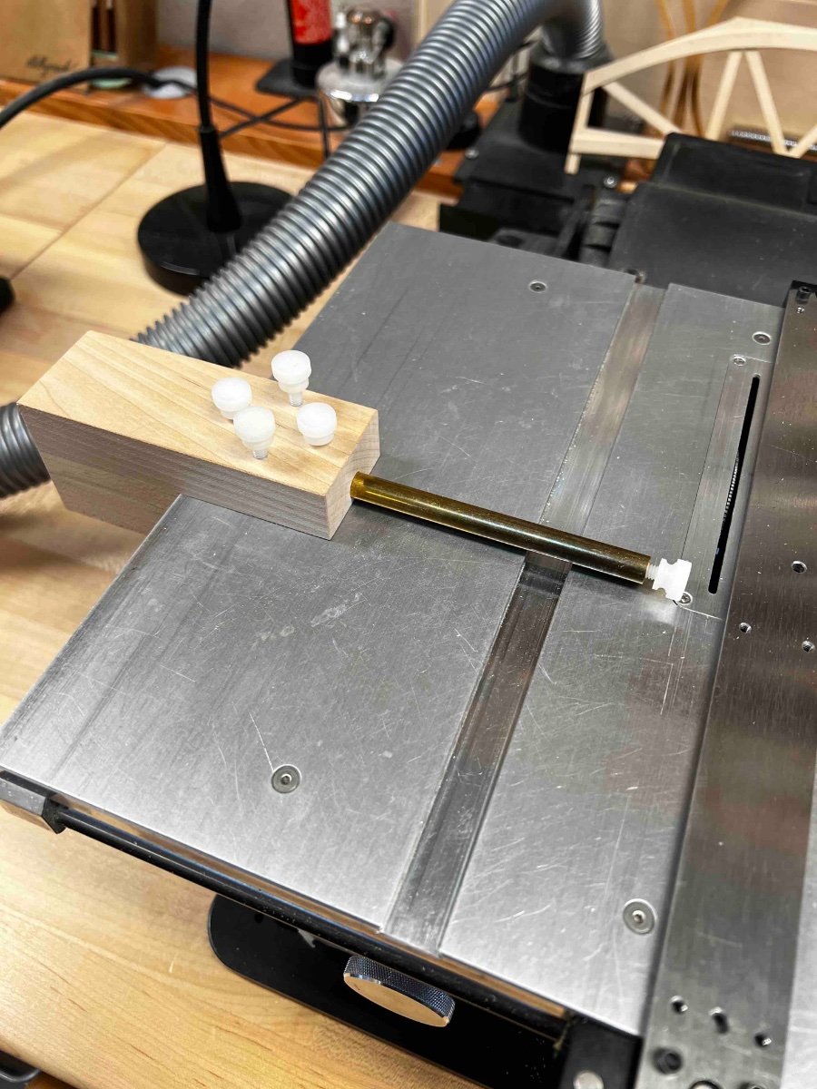
Alan, I like your "fingerboard". I have been away from the website so long, did you show any details on how you made it? I have long used one that our Model Ship World tool wizard Michael Mott helped me design years ago. The rod can slide in and out for rough distance, and then the thumb screw in the end can be adjusted for fine movements. Most of the time, I use this when I can cut the finish part on the side of the saw opposite the fence, for repeatable cuts to the same width. I just push the blank up to the jig, slide the fence up snuggly, clamp down and cut. Repeat until the blank gets too narrow for safety. Thanks again, Michael, it has worked great for years!
Mark

-
Hi Gaetan,
Yes, that looks like my wood. It was labeled S.A. Boxwood at Woodcraft stores, which I presumed to be South American Boxwood. I didn't know better at the time.
As it turned out, it is still a lovely wood, with a fine grain, and it darkens over time to a golden honey patina, like something one would expect to see in an antique ship model.
I just needed to learn how to work with it!
Mark
-
Hi JD,
I am glad it might help you. This is a case where I had never made mouldings before, I researched how everyone had done this, and tried their techniques without success. I saw that their methods worked for them, I just couldn't get them to work for me. I had to experiment until I got something to work.
I have suspected over the years that my wood--which I thought was boxwood when I purchased it over 30 years ago--is something related to boxwood but much stiffer. For example, it does not submit to bending techniques others have used; I have to steam it for longer and then clamp over a former with exaggerated curves because of so much springback. And when I freehanded scraping cutters for mouldings, the cutter waved up and down even though the grain is very fine and not the obvious cause of the waviness. Only a very stiff cutter, a fence along the cut, and a solid surface to bottom out on did the trick.
Best wishes,
Mark
-
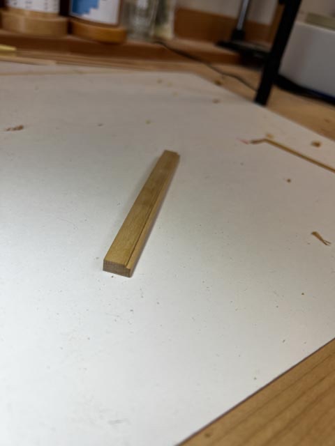
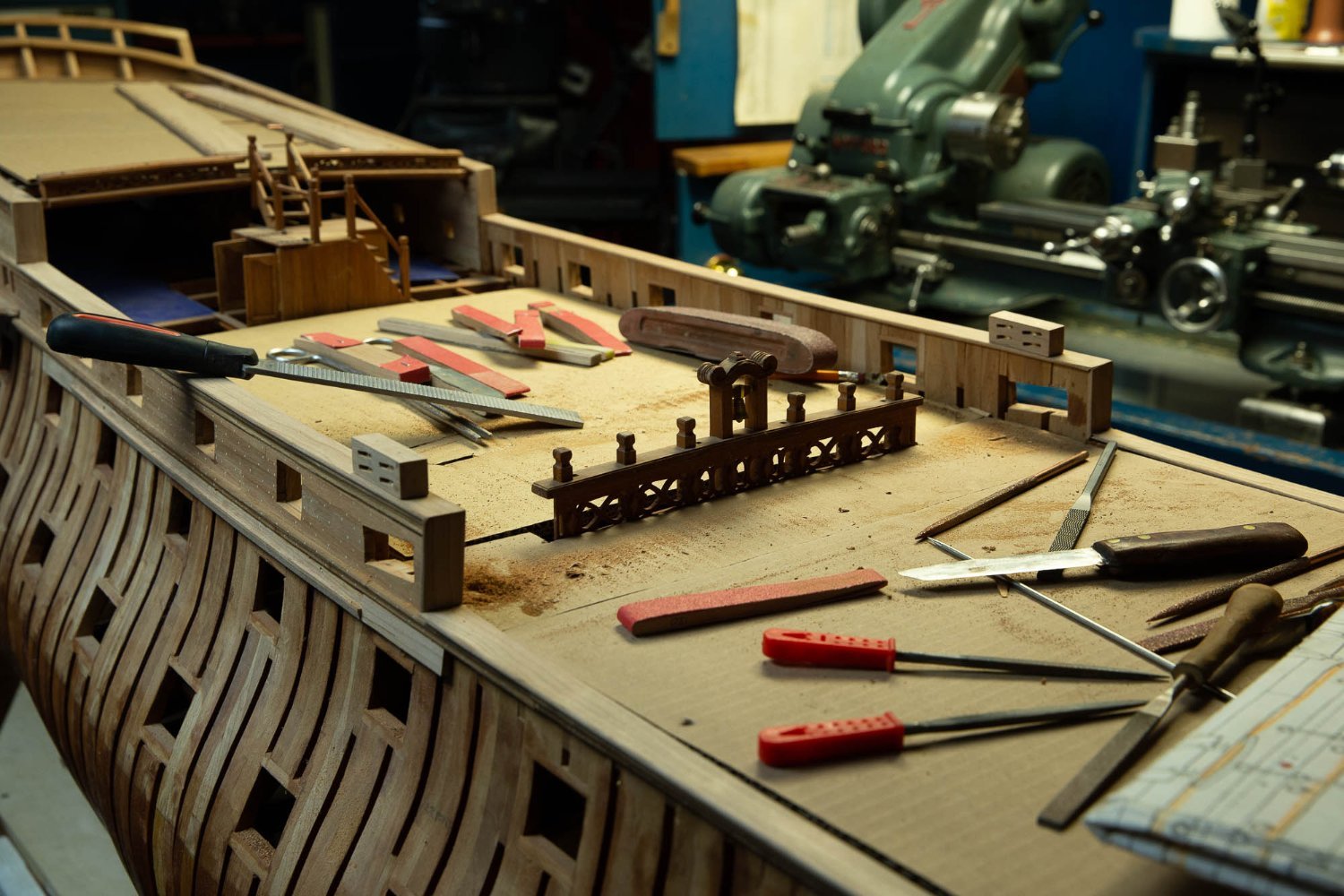
With the nomenclature conversation taken care of, the moulded railings needed to be made.
I refined my moulding cutter setup to work more efficiently.
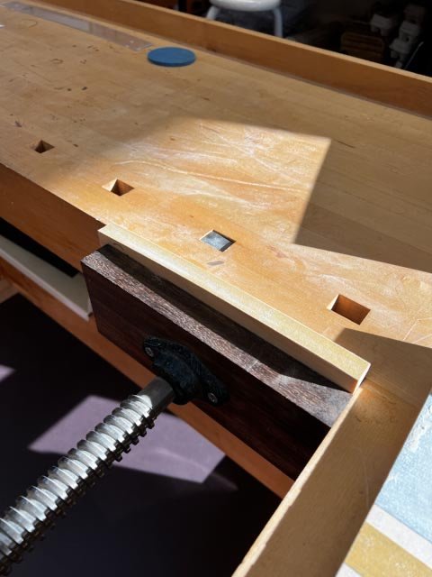
I cut the moulding profile as before in a Lie-Nielsen tool steel blank. This steel is soft enough to shape with files, but keeps its edge for long enough for a run of one set of mouldings. It is also very thick, and so it does not chatter like thinner metals I tried. I mounted it in a wooden clamp at what I determined to be the best angle of attack, with the clamp also forming a fence at right angles to the tool steel.
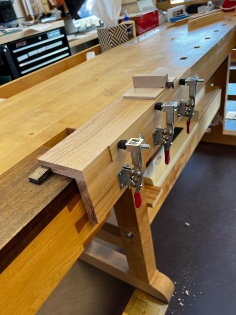
In my refined method, I built a jig that could be secured in my tail vise, and then three clamps hold the moulding blank against one side of the jig. I clamped the blank, projecting the exact thickness of the finished moulding above the jig, using a temporary spacer for accuracy. (In the photo below, you can see the profile previously used for a different moulding; I will just keep sliding the tool steel along as I need more profiles in its edge, until I don't have enough left to clamp in the wooden block.)
I have read and viewed reports from others using a scratch stock in a more free-hand manner, but my freehand efforts resulted in wavy surfaces up and down. I don't know if it is a lack of skill on my part, or I have unusually stiff wood, but I found that I really need the scratch stock to be guided with this fence arrangement to get satisfactory mouldings.
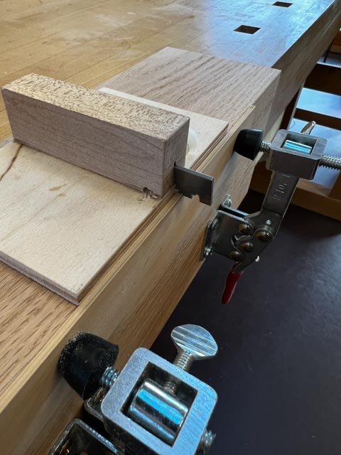
It was then a simple matter of pulling the cutter along the projected edge, using the fence to keep the cutter parallel to the blank, and cutting until the flat part of the cutter holder hit the top surface of the jig.
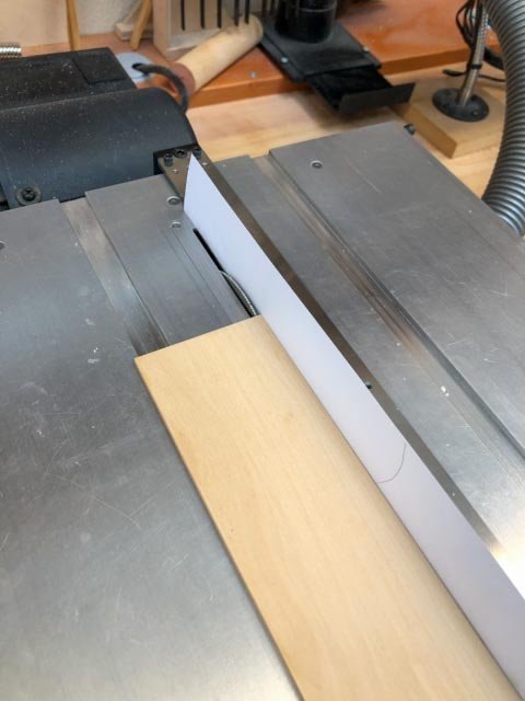
As before, I then cut off the moulding on the Byrnes saw, using a strip of paper against the fence to avoid discoloring the moulding face while rubbing against the aluminum fence:
And now perfect mouldings along the top of the waist, on top of the wider sheer strake:
Best wishes,
Mark
-
Hi Mark,
Yes, I can see how ambiguous these old contracts really are, especially when they run one idea into the next without punctuation, leaving the reader unclear whether the next phrase refers to the previous one or is a new thought. It is also interesting to see how different contracts try to say the same thing but with different phrases; you would have thought that there would have been some standard "boilerplate" text for a lot of this...
Best wishes,
Mark
-
Hi druxey and Mark,
It is nice to be back. Not quite over the covid, but fast getting there. I didn't see any warnings on my power tools not to use while suffering from Covid, so onwards I go!
It really does seem irrational that the rail on the face of the Sheer Strake is not called the sheer rail. But digging into this, I have now discovered three contemporary sources from about mid 18th century, all seemingly calling this the waist or waste rail.
There is Falconer, sometime before 1769 calling the top rail a waist rail; the HMS Berwick Contract 1768 I quoted earlier, and the Marlborough Contract, 1763, which says:
"To have a Sheer Strake Wro't fore & Aft, the upper Edge of which to be the Upper edge of the Waste Rail in Midships & 1 Ins higher from the Drift Fore & Aft, to be in Breadth 12 Ins and in thickness 4 Ins this, that the Channels be placed on the lower part thereof..."
I liked Mark's interpretation that the Berwick contract was really talking about parallel rails, not necessarily the location, but the Marlborough Contract doesn't seem to allow for this. It has the top edges of the Sheer Strake and the Waist Rail aligned with each other.
And yet, by the time we get to the Ship Builder's Repository, 1788, page 270, we have "Sheer Strakes, 2 in number, each in breadth 12", the upper edge of the lower sheer strake to be agreeable to the upper edge of the sheer rail." Now all is well, and this is later restated by Steel who also has the upper rail as the sheer rail.
I wonder if there was a transition at mid century, swopping the names to be a little more rational.
And I can't stand the irrationality of a waist rail over a sheer strake; whatever really happened here, I will call my upper moulding a sheer rail, to match the sheer strake under it!
Best wishes,
Mark
-
Hi everyone,
A long, long time away from the Bellona! Other life things have interfered, including getting Covid even though I had both vaccinations and the booster.
But hopefully things are getting going again.
I am up to the top plank in the waist, the Sheer Strake:
And I have come across an interesting question regarding the sheer and waist rails as I tackle this part of the ship. Siggi first alerted me to this, and then John directed me to the contract on the National Maritime Museum website for the Bombay Castle, which was based on the Berwick, which was a sister ship to the Bellona, and the contract Brian Lavery believes is closest to that for the Bellona.
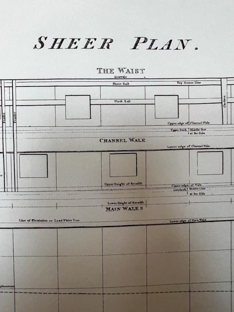
Here is the puzzle. I have long assumed that the uppermost plank in the waist is the thicker Sheer Strake, and nailed over it is the uppermost moulded rail named the Sheer Rail; and that the Waist Rail is the moulded rail below, cut through by the ports as seen in my model above. This is how they are names in Steel's plate:
And Goodwin's book, The Construction and Fitting of an English Man of War, page 57, also labels them as Sheer above, Waist below.
But, Siggi pointed me to Falconer's Dictionary of the Marine, which clearly labels the top rail as the Waist Rail:
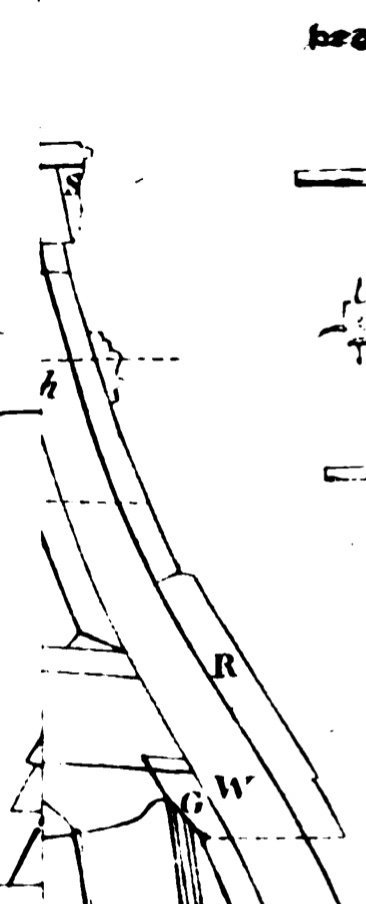
And then I looked at the Contract for the Bombay Castle, which cannot make any sense if one assumes that the top Rail nailed on top of Sheer Strake is named the Sheer Rail. It clearly refers to this top rail as the Waist Rail.
"Sheer Strake: To have a Sheer Strake wrought in two breadths that the upper Edge of the upper Strake may be agreable to the upper Edge of the Waist Rail in the Waist and one Inch higher from thence forward and from the Waist aft to be in two Breadths 12 Ins and 4 Ins thick and of English Plank in Wake of the Channels".
(both models of the Bellona, BTW, show just one strake for the Sheer Strake, not two.)
Further in the contract, the Rails are defined as follows:
"The Sheer Rail to be 8 inches broad and 3 1/2 thick the Waist Rail 7 inches broad and 2 3/4 thick the Rails in the Drift to be 6 inches broad and 2 1/2 in thick. Since the rails in the Bellona sheer drawing appear to be widest below and narrowing as they climb higher, this suggests the Sheer rail is the lowest, then the Waist Rail, then the Drift rails above.
Interesting, when our primary sources of Steel and Falconer disagree, while the contract agrees with Falconer as best I can see here. Maybe they didn't mind naming the rail over the Sheer Strake the waist rail, and the sheer rail is the one down below! Perhaps they tripped up apprentices with this one....
Best wishes,
Mark
-
Hi everyone,
Well, it has been a long, long time since I last posted. A number of life-outside-the-shop issues took over, but I am back to the Bellona at last!
My plan of work now is to complete the planking and all outboard work, so I can paint the wales and friezes with the hull on its side. Then I can install the lower deck guns and proceed at last with the upper deck. With the lower deck guns installed, I would have no hope of turning the hull on its side for painting.
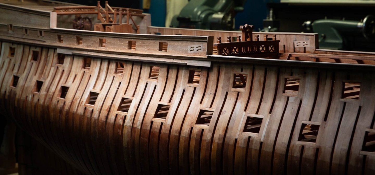
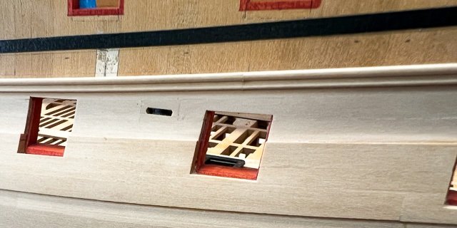
As I got closer to the top with planking, I realized that I would have to install the sheaves (main sheet and tack, fore sheet, sprit topsail sheet) in the sides before the next strake could go on. I thought this would be a fun, short break from planking. It turned out to be over a month of work. They are way more complicated than I ever realized. And I made several mistakes in their fabrication that meant starting over.
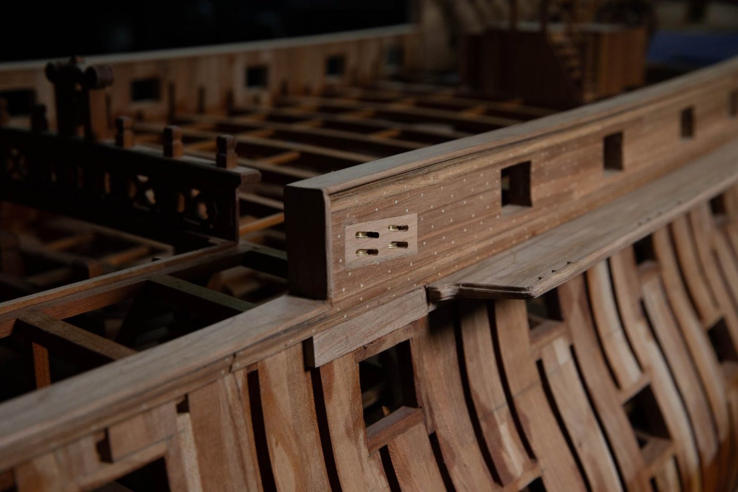
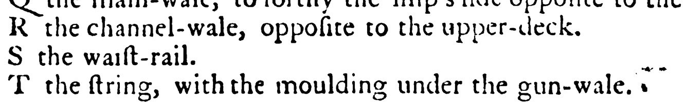
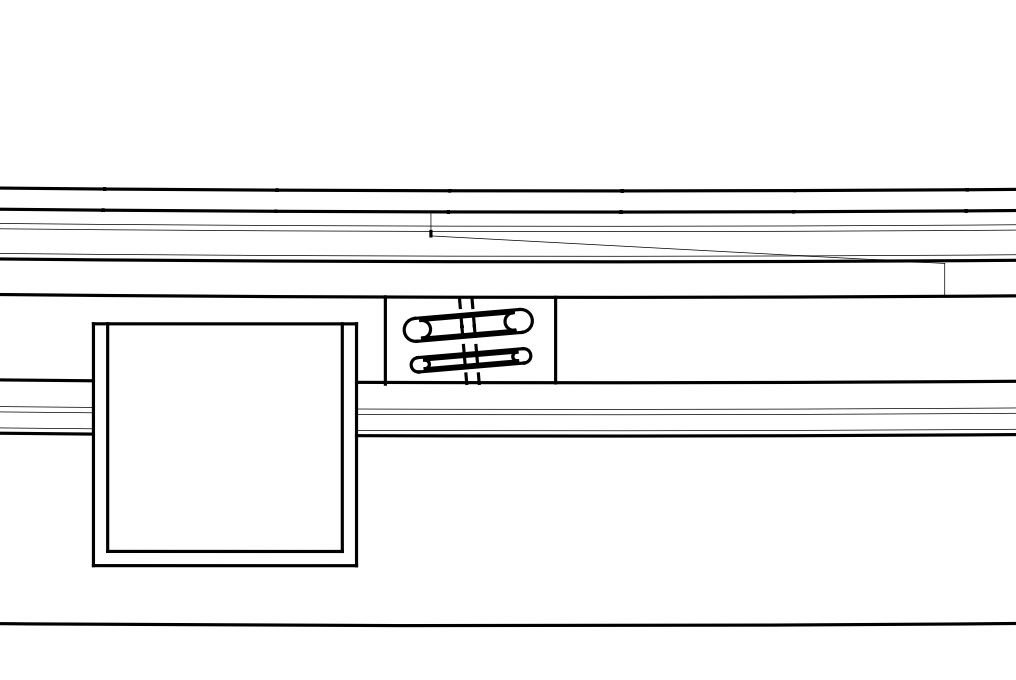
First the complication. The sheaves on the Bellona are neatly slotted between the sheer and waist rails outboard; and they slope at right angles to the side to arrive inboard just under the clamp. The inboard edge also swings up the fay to the underside of the clamp:

And the block in sheer is a symphony of angled lines. The top and bottom of the blocks correspond the sheer line of the hull at their respective locations; the sides are vertical; the sheaves are angled within the blocks to provide a fair lead for the lines:
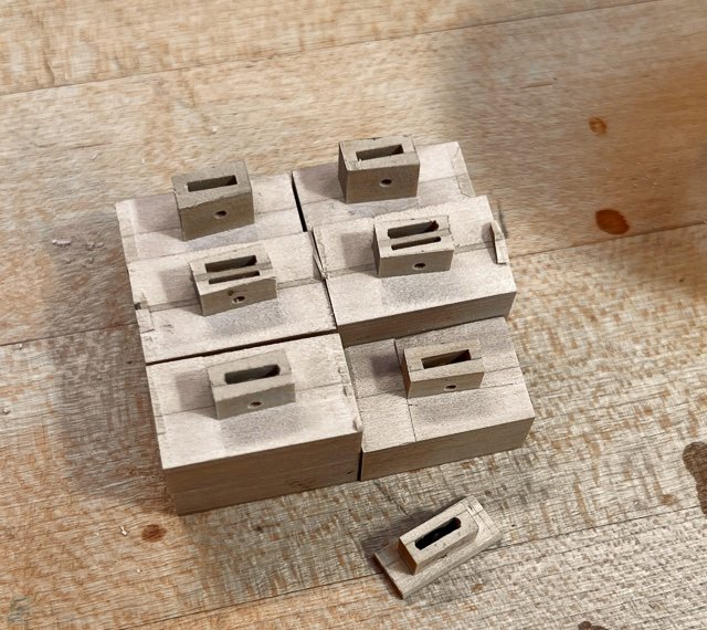
How to construct these? Since I did not have any router bits that could cut a slot thin enough, I created the slots by laminating blocks, with a groove cut in the side of one with a mill bit. For the double sheaves I laminated a thin sheet in the middle of the block. While the blocks were still square and the slots were parallel to the top and bottom, I drilled the holes for the sheave pins.
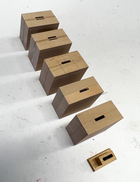
At first, I tried mounting the blocks on my Sherline rotary table on the mill; thinking I could just dial in the appropriate angles in one go. But I simply could not visualize which way angles went relative to each other, and I also stupidly misread the scale on the rotary table, cutting .3 degree rather than 3 degree angles. I ruined several blocks until I discovered this. The sheave hole in the block at the bottom of the previous photo was supposed to be sloped and you can see it is parallel ....
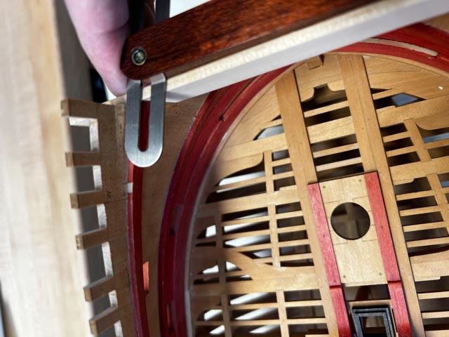
To make life easier, I turned instead to using my angle blocks to set up the mill vise at the appropriate angle (see the angles against a square in the photo below). This helped me physically visualize which way things should be aligned. And then I used a mill cutter to cut first the ends and then the sides. the block at the bottom of the photo below is an example of the failed blocks relative to the correct ones with angles:
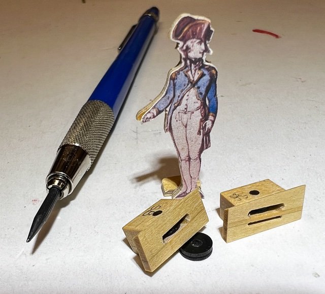
And then trimming to get the blocks to their correct sizes. I turned the sheaves in ebony, and used a tiny round file to ease the ends of the slots. Note how the tops of the blocks in the photo below have angled tops to the inner surface; this is to fay to the bottom of the clamp, as seen in the first photo posted above. Also notice how large these puppies are next to my captain. They are tiny in my model, massive on the ship. I can see the laminations on the blocks more than I would have liked; but these are all under the frieze painting and so hopefully this will disappear.
They are dressed proud where the next strake of planking will come up to them:
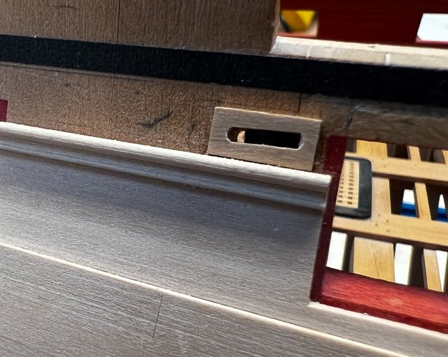
But the main sheet sheaves had to be cut into finished planking (it did not occur to me to deal with this when I was planking lower down). These were very laboriously cut into finished wood, with much trimming and fitting, trimming and fitting, to do this cleanly. It would have been better to think ahead before the planking was installed here:
All for now. On to the next strake of planking.
Mark


HMS Bellona 1760 by SJSoane - Scale 1:64 - English 74-gun - as designed
in - Build logs for subjects built 1751 - 1800
Posted
Hi everyone,
A long, long time since I last posted. I have been working away, but the recent pieces took an exceptionally long time to work out, and there was not a lot to show in the process.
I realized some time ago that I would not be able to install the guns on the lower deck until I completed the outboard works, since I would not be able to turn the hull on its side for painting once the gun barrels were projecting from the side.
So I was planking up to the top, when I further realized that I would need to install the catheads before completing the planking at the fore end of the forecastle. And those turned out to be way, way more difficult than I had imagined.
I first carefully drew true size projections of the catheads in plan and elevation:
When I cut them from blanks, I assumed I could just cut straight down according to the drawn plan. Wrong! The cat tails inboard are not only shaped athwartship according to the forecastle beam round up, but also beveled fore and aft according to the sheer of the deck. But the catheads outboard are beveled according to the sheer of the hull, which is steeper. This means the cathead twists as it passes through the hull relative to its tail. I went through a number of failures before I figured this out.
Before I could cut the hook scarps on the tails and cut the slot into the hull on the sides, I needed to locate the cat beam underneath. Then I realized that I would need to locate the beakhead bulkhead stantions since they score onto this beam and have to align with the vertical edge of the hull in this location. But in order to install the beakhead stantions, I would need to build the substructure for the beakhead just above the gundeck level, which meant that I had to drill the hawseholes before access is covered up here, and that meant I had to complete the cheeks outboard.
So, then onto cheeks. These also had a much more complicated geometry than I had first appreciated. They have a round-up athwartships to match the sheer of the main wales at the bow; they fay to the wales with a curve and also a slope back along the face; and they have an upward slant fore and aft to match the hull sheer. As I tried to fay these to the wales, the slightest change in holding them against the wale would change the shape needed. So I made supports at the correct angle and kept the lower edge flat, so I could reliably slide the cheek against the wale for the usual trim, test, trim, to fay it accurately. Then I could shape the lower edge of the fore and aft arm to its final form.
And voila, lower cheeks:
I don't know why this took me so long to work out these two interesting pieces, the catheads and cheeks. Perhaps because they are so prominent I took my time to get it right....
Now onto the upper cheeks and the hawse holes and bolsters.
Mark