


SJSoane
-
Posts
1,641 -
Joined
-
Last visited
Content Type
Profiles
Forums
Gallery
Events
Posts posted by SJSoane
-
-
Christian, you really got me thinking as a result of your kind comment and suggestion in July regarding my drawings. Indeed, your comment caused me to spend the last several months redrawing and expanding the set.
Why have I backtracked on the drawings, and not kept up with the planking on the actual model, which is now tantalizingly close to completion?
I realized that I have invested decades of research into this particular ship. And yet, I have only a number of incomplete and inconsistent drawings to show for it. They were more like notes to myself done just in time for the next part of the build. They had grown incrementally over time, as I learned more and went back to adjust things in areas where I needed. They had become a real jumble of information, sometimes contradictory from deck plan to sheer to body plan.
I also realized that I had drawn them decades before I became aware of Steele’s instructions in the 18th century on drawing a ship’s draughts. I realized that my original drawings were pretty rough and ready. Good enough for building the model, but not entirely accurate in their construction.
For the sheer, for example, many years ago I had painstakingly measured height of things like wales from the Xerox prints I had obtained from the National Maritime Museum, then plotted these on each station line. I then linked them together with a long flexible ruler. I had no idea at the time that these lines were actually created as arcs of a circle with 3 defined points at the head, midpoint and stern. Mine were close, but not the real thing.
In the spirit of creating an accurate record of my research, and enjoying the challenge of recreating the drawings as Thomas Slade would have done, I started a redraw.
And then I came to realize just how distorted the original Admiralty prints had become over 250 years. The height of a toptimber in the body plan was as much as several inches off relative to the same height shown in the sheer, and the scale at one end of the sheer was several inches different from the scale at the other end of the same drawing. The scale itself was so fuzzy that measuring against it could be interpreted as much as an inch or two either way. The inboard works drawing was off by half a foot in some places. This didn’t matter for a 3/16” = 1’-0” model, but it mattered a lot when trying to draw the body plan according to the Steele instructions, when a few inches off meant that the geometries in each frame would not line up.
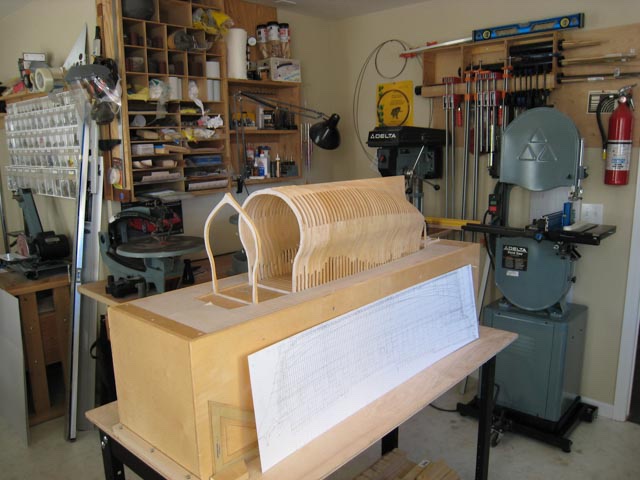
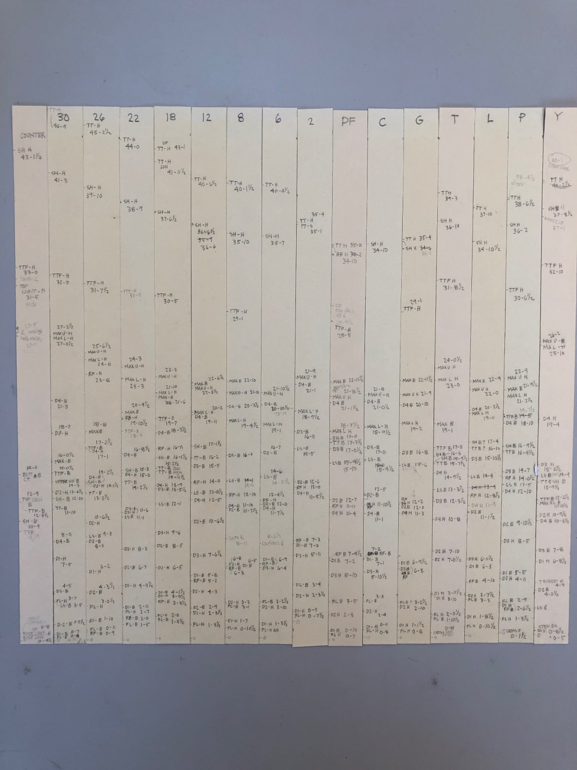
So, I had to measure and fudge, until I could get the geometry to align with the measurements off the original prints. I made tick strips of relevant heights from the body plan, then adjusted a little where the sheer showed something different, then tried the geometrical construction; going back and forth until everything lined up.

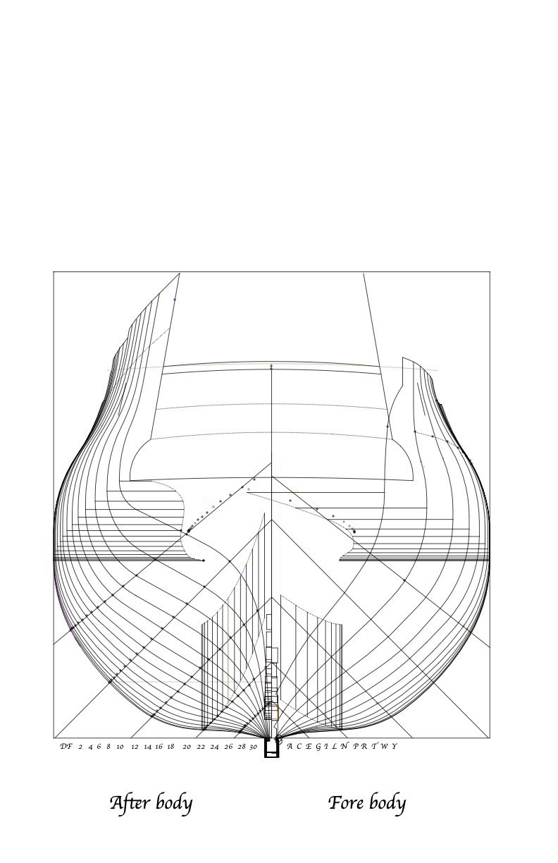
I learned more precisely how the geometries of a frame related to each other:
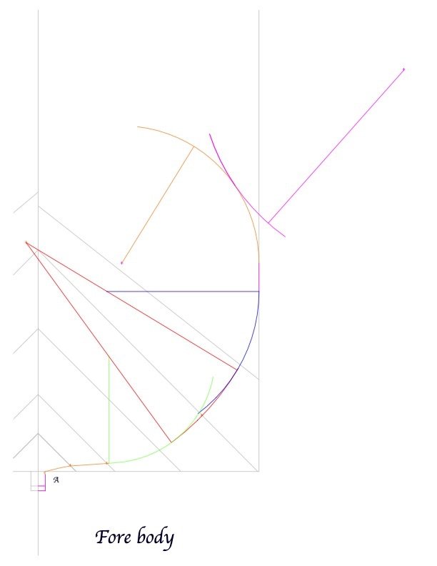
and here is the complete body plan now accurately constructed:

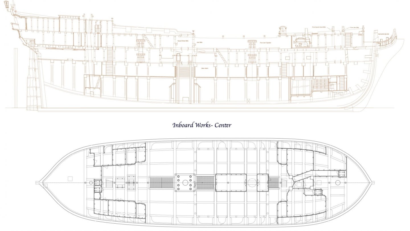
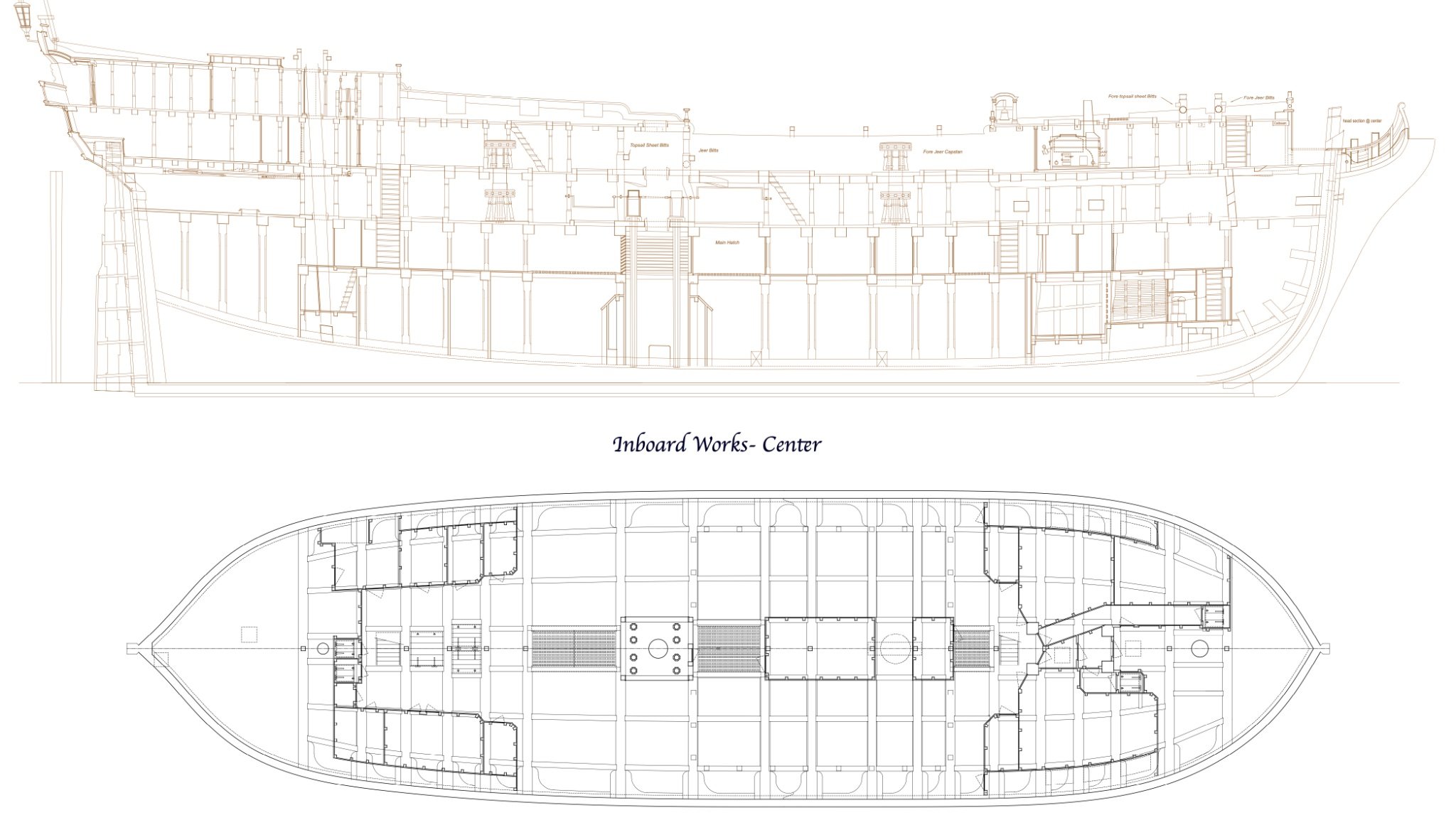
From this, I began redrawing the inboard works and sheer. I also decided to draw the orlop and holds including the magazines. I never drew those, because my dockyard framing system omitted the magazines; and everything below the gun deck was a mystery to me. Now I know much more about what was going on down there.
These are still works in progress, shown here mainly to let you know that I have not fallen off the face of the earth, or stopped work on the Bellona.
I may post some insights I gained while drawing these, about the design and construction of these ships. For example, I finally found an answer to a question I posted several years ago about the quarterdeck beams seeming to raise their roundup as they approached the stern. Now I know what is going on, and I will share in a subsequent post!
Best wishes,
Mark
-
JR, thank you so much for the information on the aft stool or not. It seems compelling that the stool was in use by the time of the Bellona in 1760. The only remaining question is that the rig at this time, as best I can understand it, had only a topmast with a pole on the mizen, no topgallant mast. So there would not be a backstay for the absent topgallant, only a backstay for the topmast. So there would be only one line rigged to the stool. Maybe that the way it was. Or, maybe there was a backstay on the topmast pole running to the stool? Any guidance here would be much appreciated.
Best wishes,
Mark
-
Hi druxey, for some reason, maybe having to do with the grain or the stiffness of the wood, or poor hand coordination, I could not keep the cutter at a consistent angle to the table top. So the top edge wavered too much. Mounting the cutter in a handle at least keeps the angle constant for me. Still much to learn!
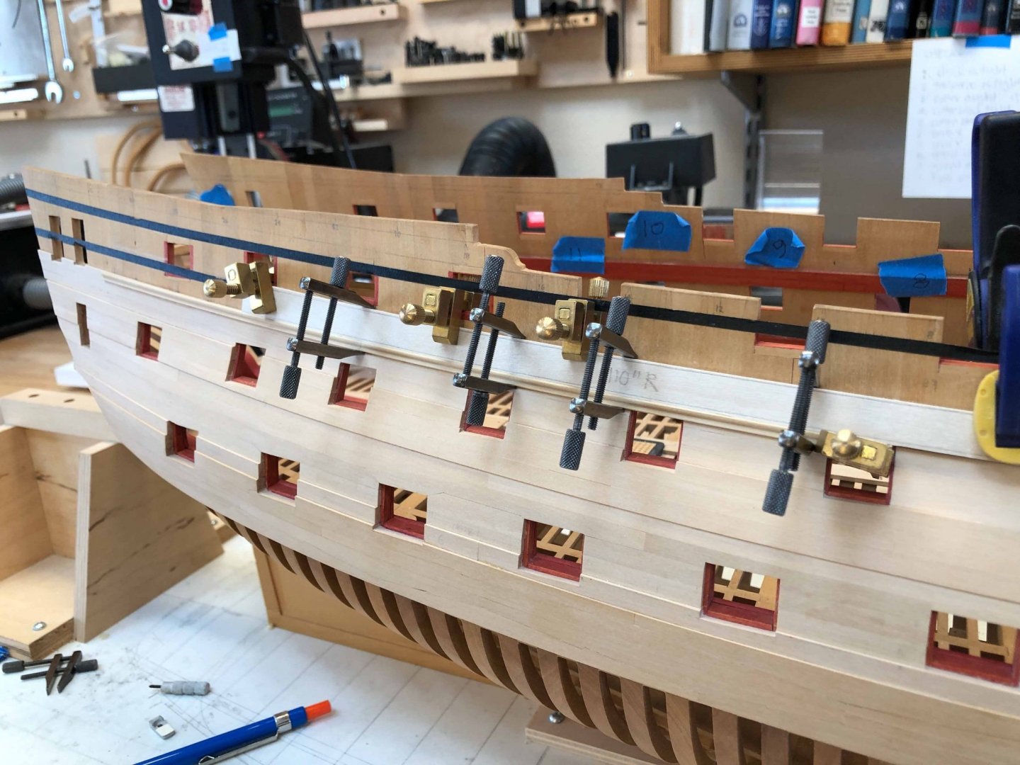
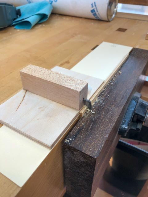
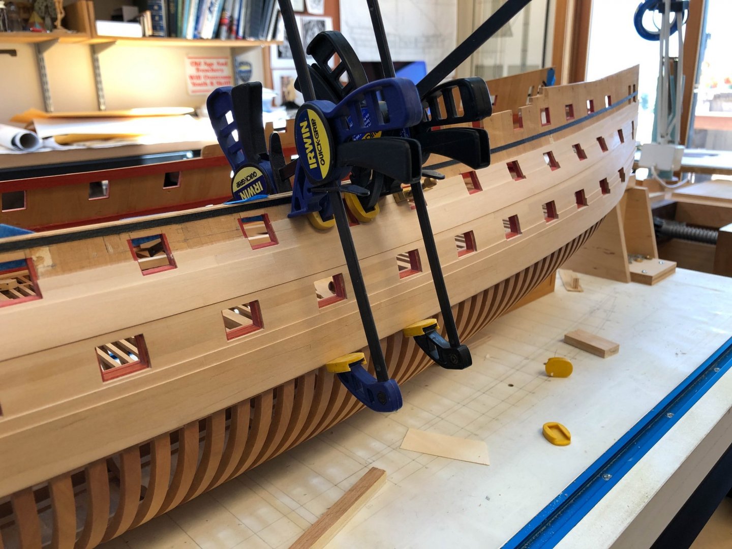
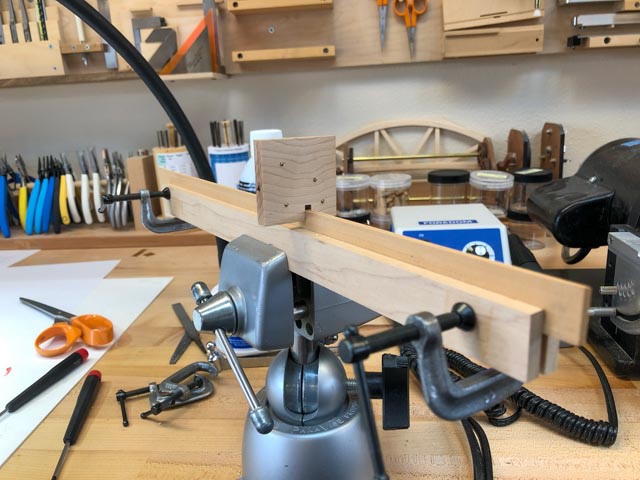
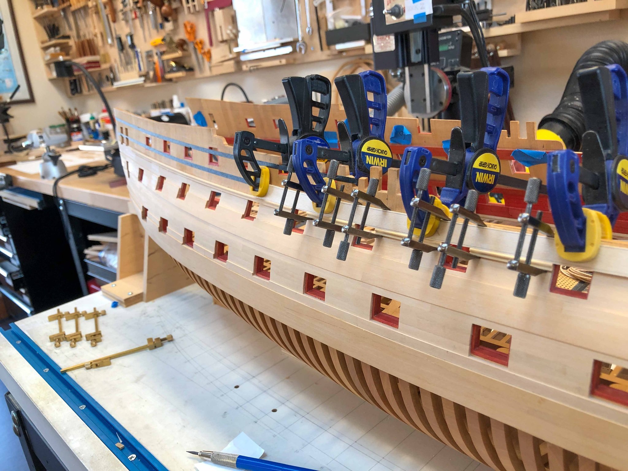
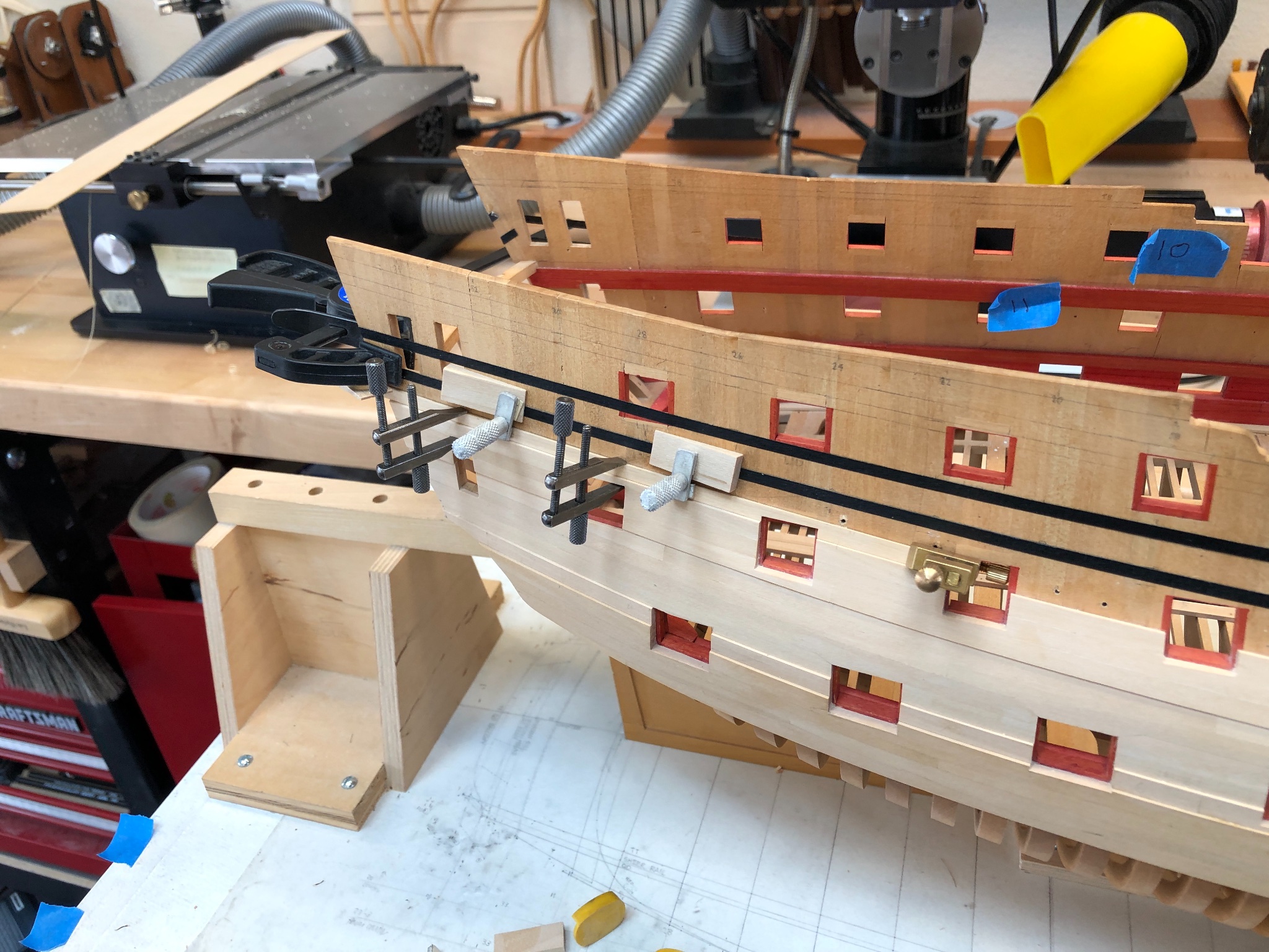
At last, I was able to start putting the waist moulding in place. I tried drilling holes for pins to keep things in place, but it was too sloppy to force the gradual curve and keep it there while the glue dried. So I made some battens that ride on the top of the planking edge underneath the moulding, clamping them to the ship side. Then it was a simple matter of clamping the moulding vertically to the batten. It is making a perfect, sweet, curve.

- albert, Jorge Diaz O, Stuntflyer and 19 others
-
 21
21
-
 1
1
-
-
Thanks so much, Marc, it is a good thing I am not doing this for a living!
I wish I could think that everything I have learned will be applied to another model, but at the rate I am going, this is pretty much going to be it!
- Hubac's Historian, druxey and mtaylor
-
3
-
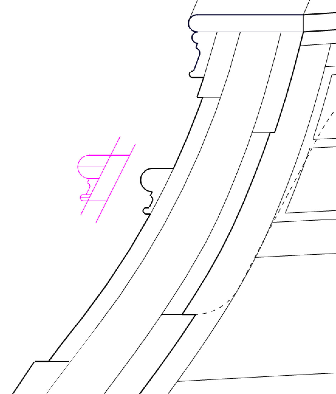
Much fun figuring out how to get decent mouldings! But I finally figured it out.
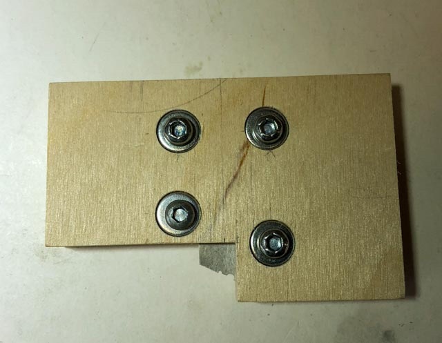
First round: I used an old exacto knife blade, shaped with a grinding wheel in the lathe. At this point, I was still trying to cut the blank at the angle of the tumblehome. I mounted it in a holder:

I expected the handle riding against a fence to stop at the right depth:

But this failed miserably. For some reason, the depth was not controlled at all, and the top edge waved up and down. And the cutter did not define the outer edges, just the face; so the moulding top curves did not gracefully flow into the sides of the profile; there was always a little ridge or the curve got cut off.
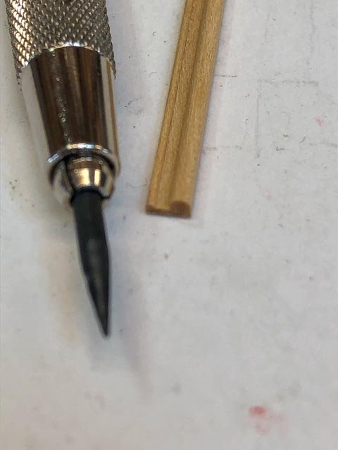
Next idea. I made a new cutter, now abandoning the idea of cutting the moulding at the angle of the tumblehome. It was too complicated, and at this scale did not show at all. So now I tried a simpler profile, straight up and down, and I provided sides to the profile that would run against the blank so the curves would flow evenly down into the edge of the blank. The edges of these sides were softened with a file so they would not cut, only guide.
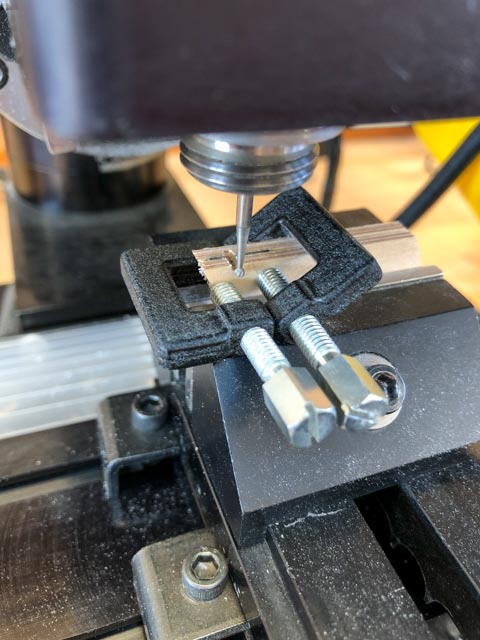
I cut the profile in a Lie-Nielsen A2 steel blank (for his moulding plane; https://www.lie-nielsen.com/products/beading-tool-blade-blanks, 5 for $10). This made a fantastic cutter. I was able to shape it partly with ball end mills in the milling machine, and partly with files. And its greater thickness greatly reduced chatter. Lie-Nielsen claims it does not have to be hardened, and I will see if it starts to dull or not before I am done with this shape.
At first, I tried just running the cutter along the edge of the blank, counting on a fence to stop the cut at the right depth:
This did not work well at all. The upper edge was amazingly wavy. Perhaps the more powerful cutter grabbed at grain more aggressively.
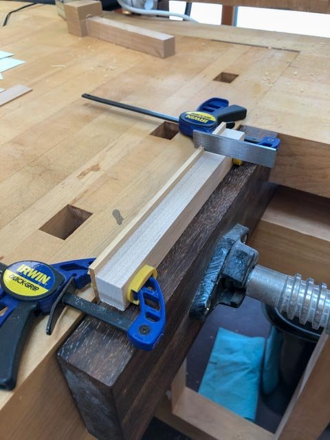
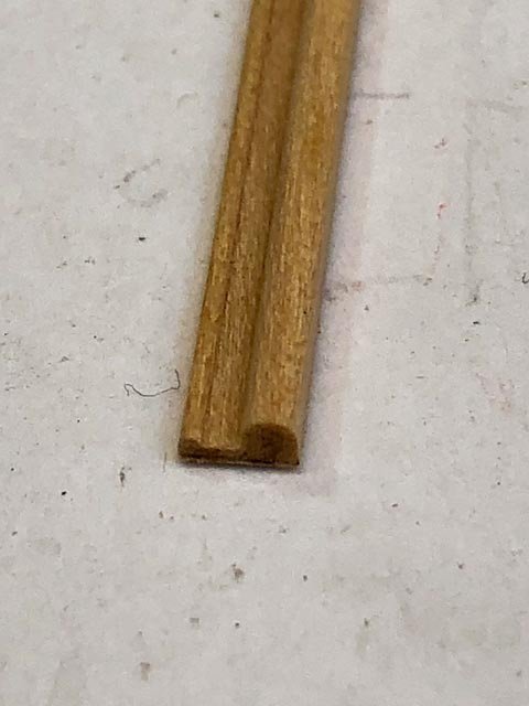
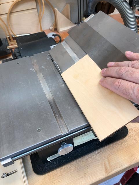
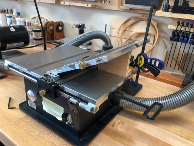
So the final idea, which works perfectly, was to build a holder for the cutter, angling the cutter at 15 degrees, and with a fence riding against the side.
The workbench top now acts as a stop. I put a number of slips of manila folder and typing paper between the cutter and the workbench top to lift the cutter up so it just takes a whisper of a cut. When it cuts no more, I take away a slip of paper from underneath, dropping the cutter down slightly, and cut again. I do this repeatedly until the full profile is cut. You can see below the sweet curl of a cut coming off the cutter. The exacto blade cutter only shaved off sawdust.
I then cut the blank to the right thickness, keeping a piece of typing paper against the fence. In my earlier efforts, the metal of the fence was discoloring the moulding; the paper keeps it clean.
And voila, perfect mouldings:
This turned out to be much more difficult to control than I had originally expected, but a lot of experimentation and I got there.
-
Thanks, Ed, it has been a pretty long apprenticeship!
I started working on mass producing the waist mouldings. In my first experiments, I scraped the moulding on the edge of a wide blank, then cut off the moulding at its appropriate width. I have to use the angle table on the Byrnes saw, since my moulding is angled for the extreme tumblehome. This turned out to be exceedingly fussy, resetting the fence for each new cutoff, and aiming for a tight tolerance to keep them all the same thickness.
I decided to try another idea, which is to cut the blanks to the right thickness, and then use the scraper with a depth stop to avoid cutting beyond the correct thickness of the final moulding.
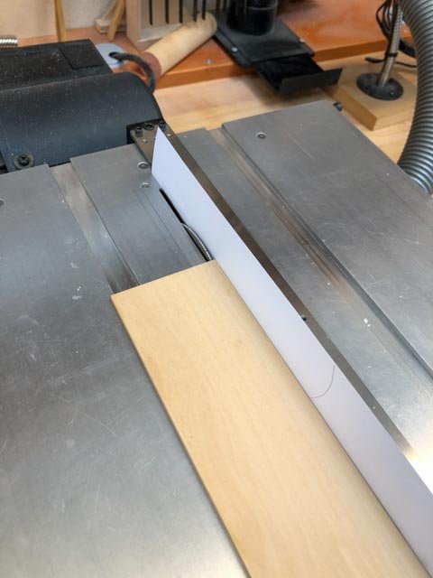
The first step is to produce a number of parallelogram blanks of exactly the same thickness, on the tilting table.
So, I built a jig. It lets me slide an auxiliary fence up to the saw blade, with a spacer of the appropriate size to offset the auxiliary fence from the blade:
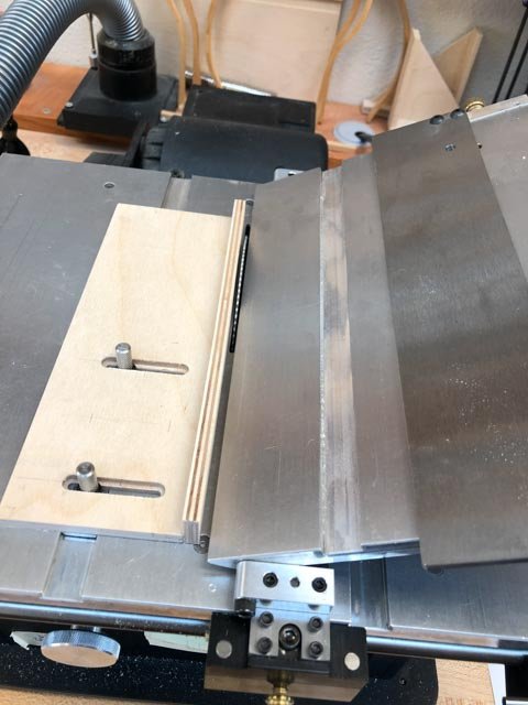
I then slide the blank with its angled edge already cut up to the auxiliary fence. This allows me to slide the tilting table fence down to the blank, thus setting the fence for that particular blank at the exact distance needed beyond the saw blade:
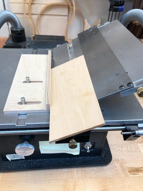
And then I remove the auxiliary fence, and cut holding the blank firmly against the tilting table fence:
Only a day's worth of thinking and building. This is why this project is taking so long!🙃
Mark
-
Thanks so much for your comments, druxey and Ed.
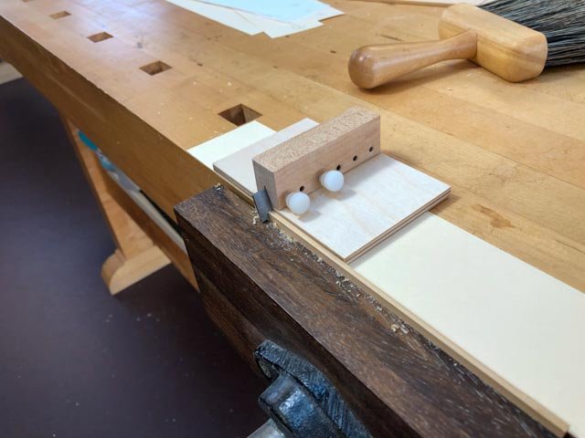
druxey, good idea about pre-drilling the mouldings. The trunnels will be noticeable when finished, and predrilling can keep them all in a constant position up and down. It is a small target for the drill in the concave part of the moulding, so using a fence on a small drill press can keep me in the safe zone. I have been concerned about how stiff the moulding is, and how it is not easily forming the sheer curve without something to pull it up to. But I discovered last night that my test piece was cut too thick. I am thinning it down today to the correct thickness, and hopefully it will become a little more pliant.
Ed, I regularly look to your books on the Naiad for advice on construction methods; you provide a great road map for the these specific kinds of details. Along with David Antscherl's Fully Framed Model books, I have some great published guides in my shipbuilding apprenticeship!
Best wishes,
Mark
-
Thanks so much, Siggi, I have been away from the shop for a long while, and only today saw your posting. I seem to recall that you did put the stools on your model of the Dragon. It looks like it was a detail that changed back and forth, so either way would be correct. I will follow the image you included of the Dragon, showing a stool. It is more consistent with the rest of the ship!
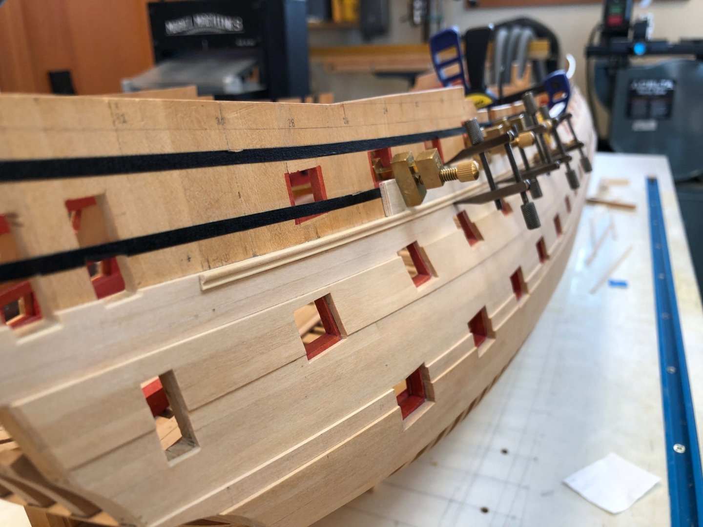
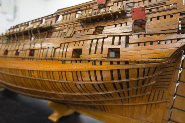
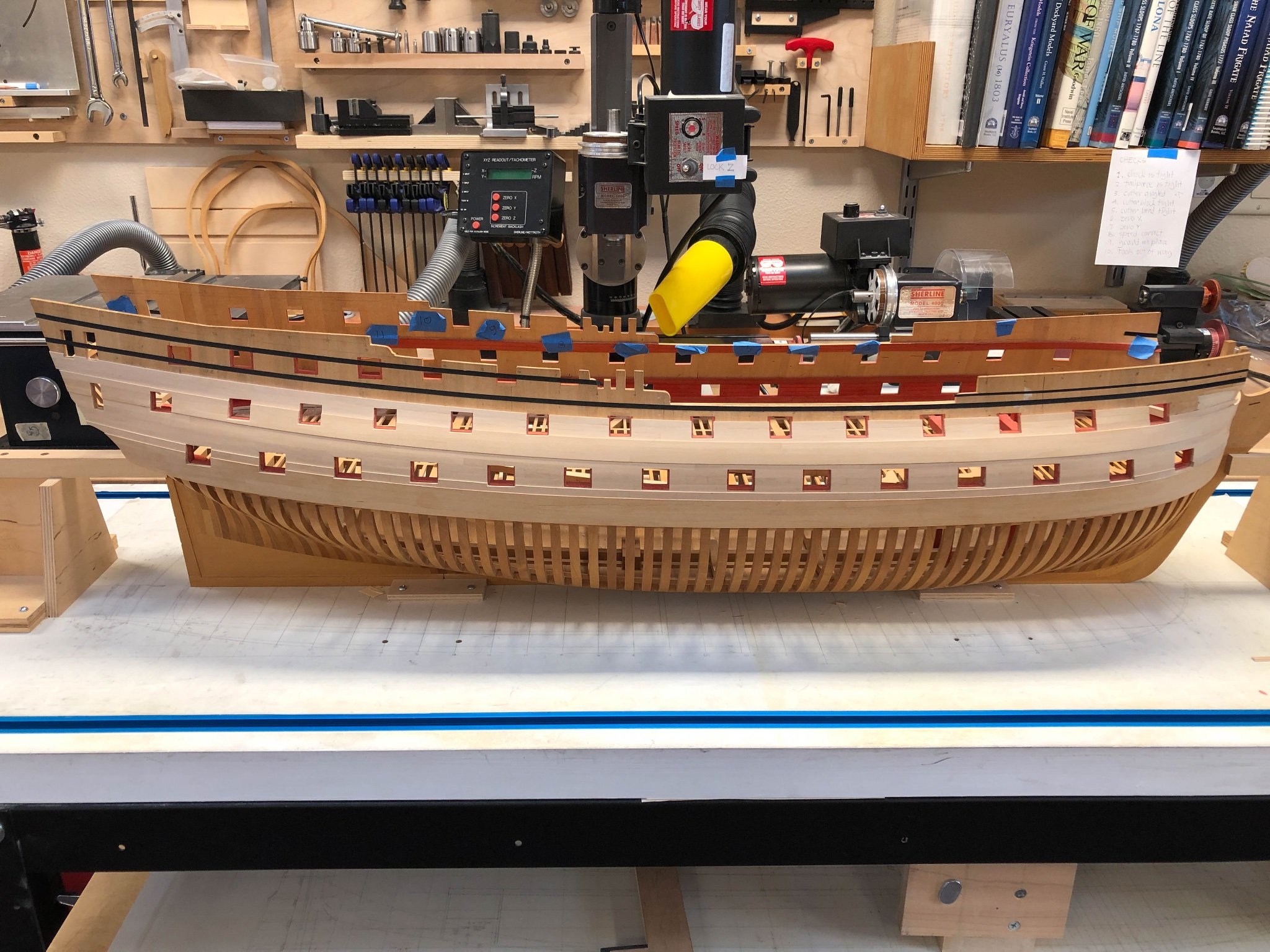
I have been taken away from the shop for a good period of time, only able on occasion to install more planking. I have just about finished up to the waist rail, needing only the strakes at the bow which bend outward to support the cathead. It was a fairly simple matter of spiling to the plank below, trimming for ports, and measuring the widths in the normal way using a planking fan. Slow but steady!

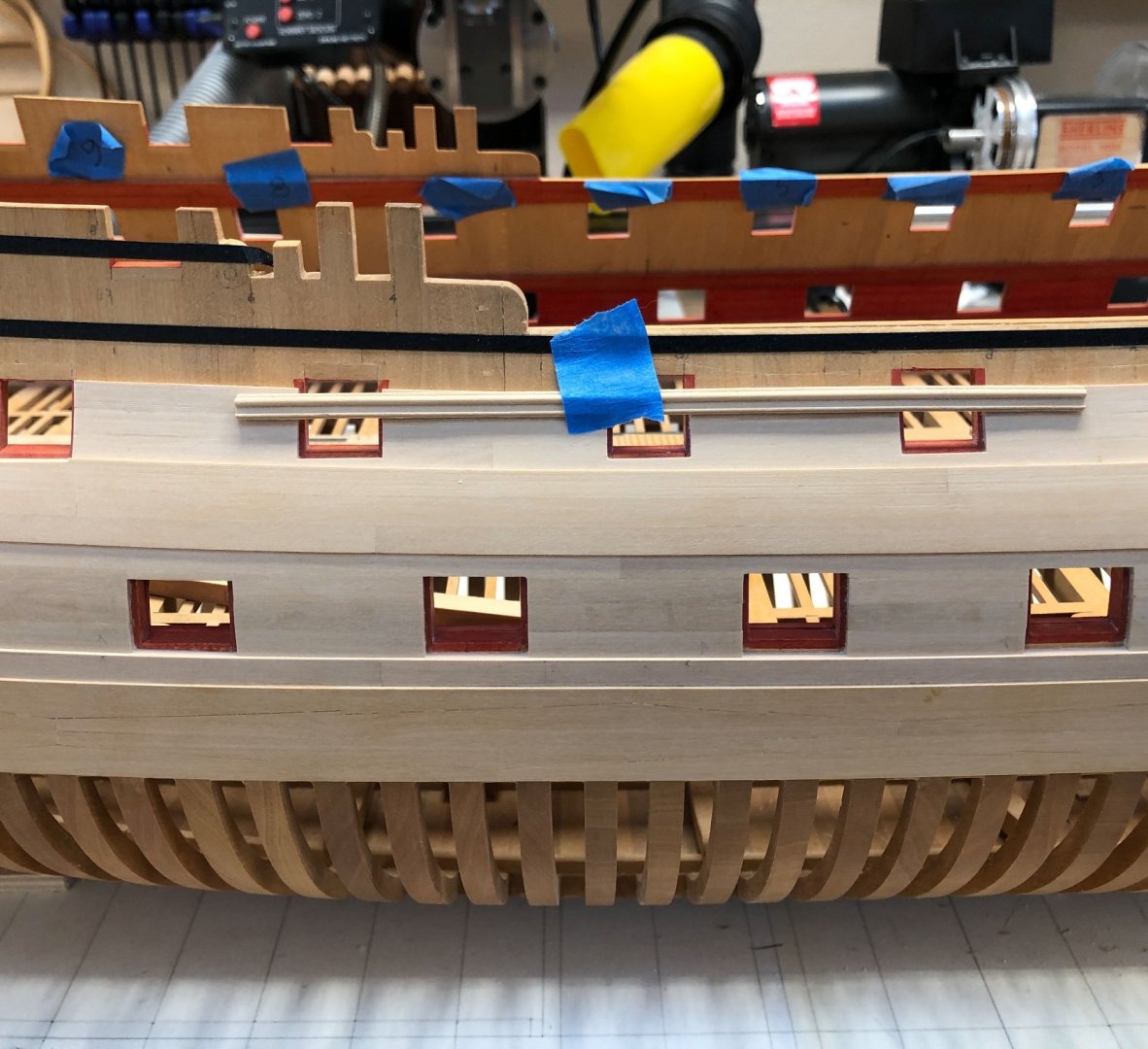
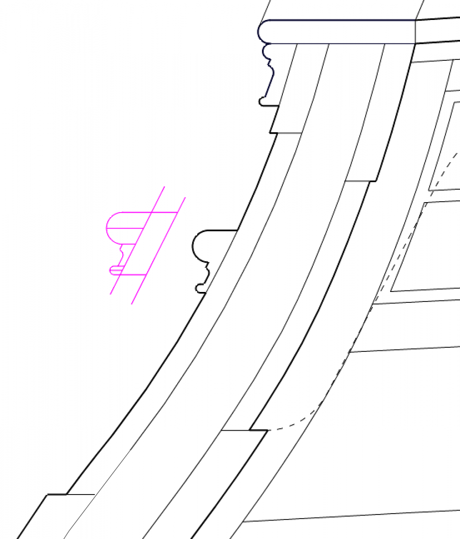
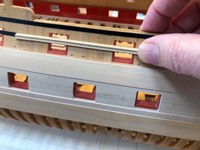
This then brings me to the fun part, installing the waist moulding. I have taped a sample to the side to see how it will look, and how I will install it. I read in Ed Tosti's Naiad book that the moulding should be installed in long lengths, then cut away for ports later, to ensure a smooth curve along the sheer. This makes sense to me. I am thinking about clamping a former along the upper edge of the planking, then pushing the moulding up to the former and drilling for pins. The pins will later be used to align the moulding as it is glued. I still need to think how I can clamp this against the hull, without damaging the very delicate moulding.
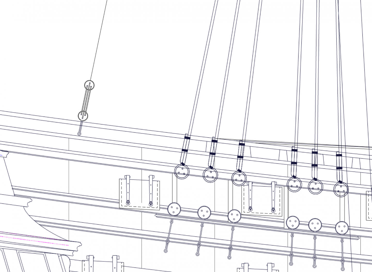
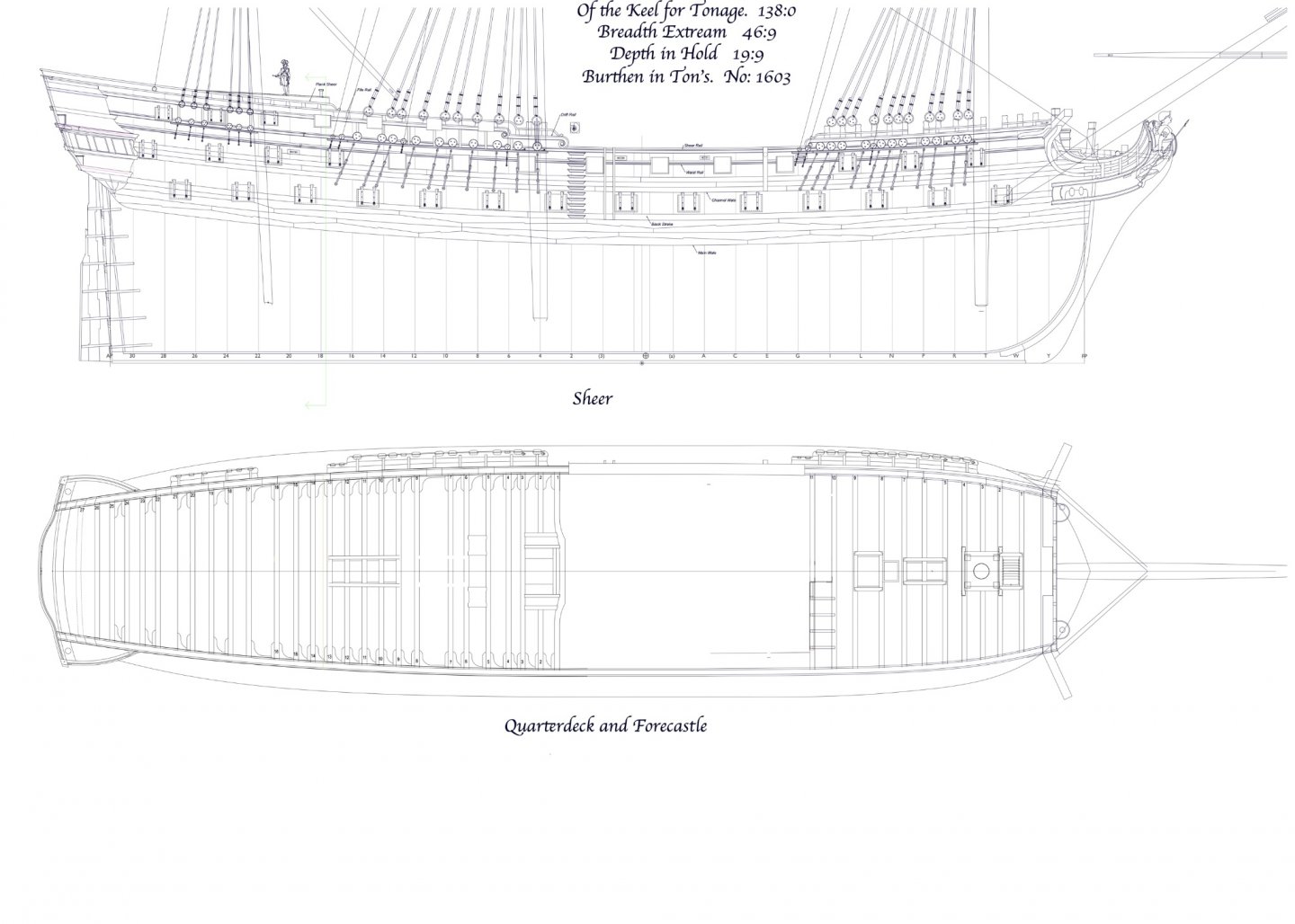
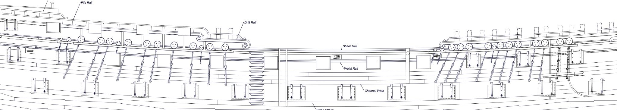
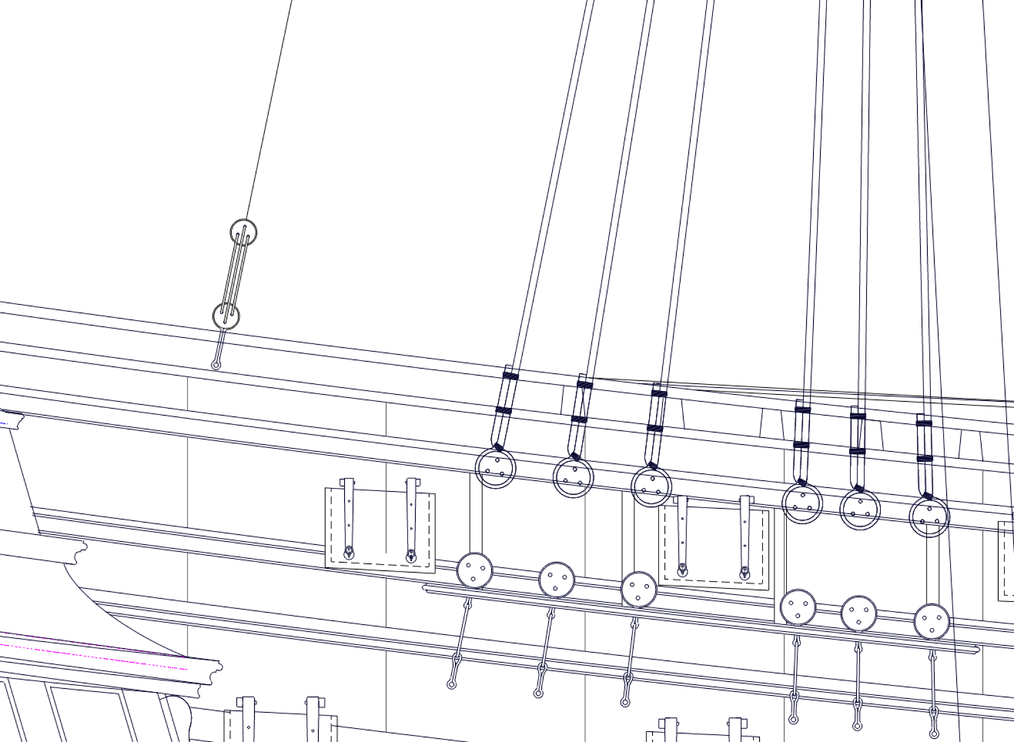
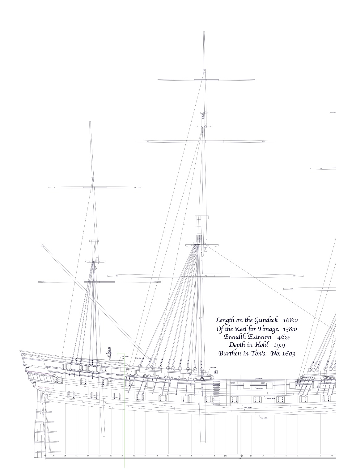
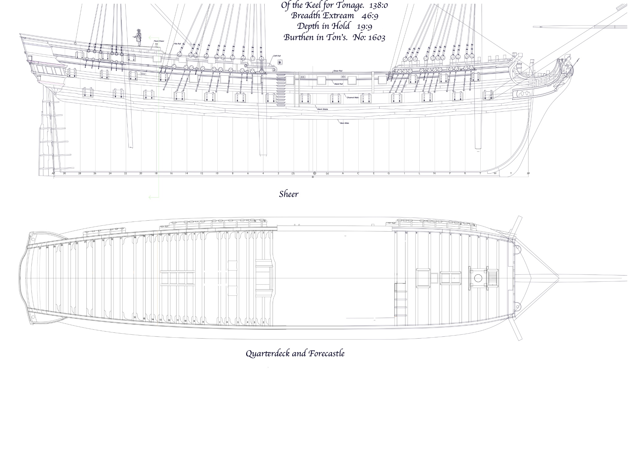
In preparation for this, I also had to look again at the sheaves in the sides for the fore sheet and spritsail sheet, the main tack and the main sheet. Brian Lavery's book on the Bellona showed the first three as separate blocks in the sides at the waist. But I was unable to find other examples of that in the period, and Lees' book on Rigging says the fore and spritsail sheets were combined in one block at the middle of the waist during this period. So, I followed this, as seen below. The main sheet is to the far left in the drawing, and the main tack is just under the fore channels to the right of center.
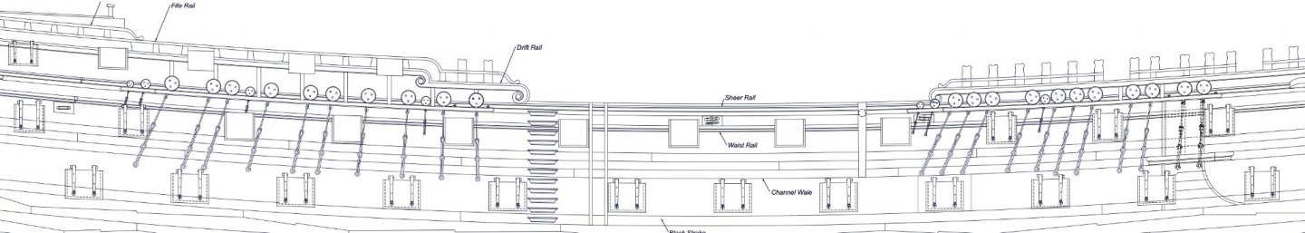
I also puzzled over how these blocks fit the sides. Every image I could find of ships in the period show the forward most blocks above the waist moulding, not cutting into it. But when I drew this with the blocks horizontal to the waterline, they cut into the clamps inboard. I did not think this would have been done, given the structural importance of the clamp at the waist. Then I noticed in the John McKay book on the HMS Victory that the blocks were perpendicular to the sides, not horizontal. So I drew it this way, and the blocks clear the inboard clamp very nicely. This is how it looks:
All for now!
Best wishes,
Mark
-
Marc, Beautiful work. I am super impressed by your piercing work. Much to learn from this for all of us!
Mark
-
HI Siggi,
I have been away for a while, just saw your postings on the frieze. Beautiful painting! I am starting to look at the frieze for the Bellona, and they are quite complex paintings. I suppose on the actual hulls they used large house painting brushes!
Mark
-
Marc,
I have been out of touch lately, just catching up. Nice line of reasoning on the color question. I look forward to hearing if you find some other hints or leads on this!
Mark
-
Hi Don,
Others may know better, but I believe the Bellona model with the canted frames on the starboard side probably was not copied much, or even followed on the Bellona itself, because the crooked wood was becoming increasingly scarce and expensive by the mid 18th century.
I know how it is to decide which evidence to follow when trying to reconstruct an old ship. I decided that the port locations, if drawn, as are accurate a bit of information as you going to get, and so other things are going to have to adjust to make this possible. Having said that, my original admiralty drawing of the Bellona shows the upper ports towards the stern with three different locations dotted in; they were clearly trying to reconcile the conflicting needs of the internal arrangements, the desire to avoid cutting frames, and so on. No one perfect solution.
One idea I have seen in contemporary models is that the frames get thinner fore and aft, or the upper futtocks or top timbers are offset a little on the lower part of the frame, to avoid ports. Since you already made the decision to keep the frames a constant width fore and aft all the way to the top, this option is not available to you any more.
If your framing will be covered by planking, you might just let the cut frames disappear into their plank coverings, and no one will be the wiser!
Mark
-
On 5/6/2021 at 2:16 PM, allanyed said:
Mark,
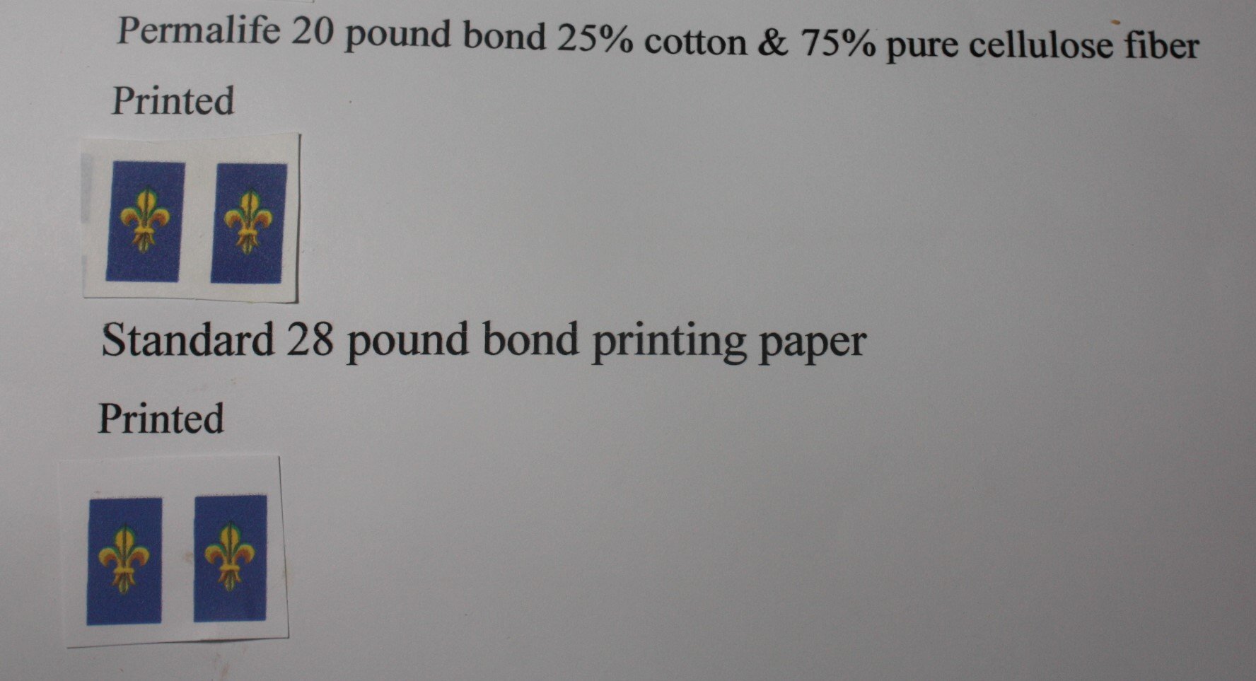
I bought the samples of several types of archival paper and printed and painted on each of them. The two best results were printed rather than printed and painted or just painted. I drew the fleur-de-lis on TurboCad with various colors then printed on each of the six different archival paper samples.
The samples that were painted on top of the printed samples were not nearly as neat in the details even using a super small high quality brush. Of course shaky old hands may have had a part in that.The thinnest paper samples would have been good when gluing to the wood, but the printing was not nearly as crisp. I copied in place to double up on the color saturation but saw no difference on any of the samples. Some of the paper samples were pH neutral, and these were very thin but the color was not as crisp. Painting on these was no problem, but for these tiny pics, they did not look as good as the printed as mentioned above. For other items I will likely paint on the thinner paper, or at least give it a try.
Two best results are below showing the single layer print on the paper identified. Each blue rectangle is 5/16" wide by 3/8" high.

Hi Allan,
Sorry for the delay; just got back from a trip to Denver for a wedding...
So it sounds like printing on the permalite 20 pound bond was the best bet. I am guessing you did not stretch it like watercolor paper in the first place, since you were printing on an ink jet printer; did the paper wrinkle when you glued it onto the wood? What kind of glue did you use?
I am also impressed with your TurboCad skills in drawing forms like this!
Best wishes,
Mark
- thibaultron and mtaylor
-
2
-
-
6 hours ago, allanyed said:
Thanks Chuck. A quick search came up with the following supplier who offers samples of different papers to try for $2.
https://www.archivalmethods.com/category/paper-tissue. I am going to give these a try to see which is/are best for this kind of application.
Fixatives with UV protection were easy to find on Amazon and at Michaels which is always a fun place to visit when I need paints or other goodies.
Thanks again!
Allan, Will you post the outcome of your experiment? I am very interested to see an archival way forward on this fascinating topic!
Mark
- druxey, thibaultron and mtaylor
-
3
-
On 4/27/2021 at 4:03 AM, allanyed said:
A couple posts were written regarding painting frieze work on paper versus directly on the model on Siggi's fantastic Tiger 1747 build log. Posting the subject here rather than bog down his log.
I have painted mainly directly on the model at times, but on paper at times as well. Recently painted small fleur de lis directly on the model and was not happy at all so did them again on paper. Based on anyone's experience or knowledge on this, what is the best paper to use? I presume thinner is better so it is not as noticeable when applied to the model. Also, concerns about what will hold acrylic artist paint best without degrading quickly. I have at least one example where painting on bonded paper then finished with a poly coat has shown no signs of degradation for just over 15 years so far. The reason I originally chose bonded paper was that it is commonly used in art work involving pen and ink and/or ink markers due to its strength as it is made of at least some rag fiber. A former art teacher gave me that advice but I am open to other proven ideas.
Also, in place of India Ink or paint for black strakes, does anyone have any plus or minus experience/comments on using permanent marker pens to stain the strake before it is set on the hull?
To add to Allan's question, would it make sense to paste the paper frieze onto the hull BEFORE attaching the mouldings above and below, so there can be a slight overlap of the moulding over the paper, keeping a clean line between the two?
Mark
- thibaultron and mtaylor
-
2
-
-
I forgot to mention in the last post that this question about the mizen backstay is a good example of a challenge I have faced working on this project, where I look for examples in other models or drawings to answer a question. I have a great tendency to see only what I expect to see. And if an example is contrary to what I expect to see, I tend to think that there must be a mistake or an omission in the model or drawing. In this case, I really expected this to be a stool. And when I could not find one of the right period with a stool, I assumed that the model builder or draughtsman just "left that detail off".
That is why it is so great to have many eyes in this website, each bringing a different way of looking at things!
thanks again.
Mark
-
Hi Alex, Mark and druxey,
Thanks so much for you thoughts on this. Alex, I think you found the key to the puzzle. I am assuming the Medway at 1742 also had a mizen with only a topmast, not a topgallant. So it, too, would have only one backstay at the mizen.
Unless someone knows of another piece of rigging at the mizen with deadeyes in this location, I will assume what we see in the Medway is the backstay to the mizen topmast. It appears to bolt directly to the side, perhaps this is what Lees was calling a deadeye plate as one of the possible rigging arrangements at the mizen topmast backstay.
I think, problem solved. thanks!
Mark

-
Hi druxey,
My copies of the original 1759 Bellona draughts show the same thing as the model of about the same date; 3 and 3, no stool.
I confirmed that the ports were moved at the stern in the later 1780ish model, leading to a different arrangement of 4 + 2 deadeyes to avoid a port.
But no stool or other backstay support in either model.
A mystery....
Mark
-
Thanks, druxey, doing the moulding afterwards sure simplifies the next steps of planking!
Got the first plank on above the channel wale today. Gets me back into the groove.

While waiting for the glue to dry, I started looking forward to outboard fixtures and fittings.
I drew up the channels, and discovered a few questions.
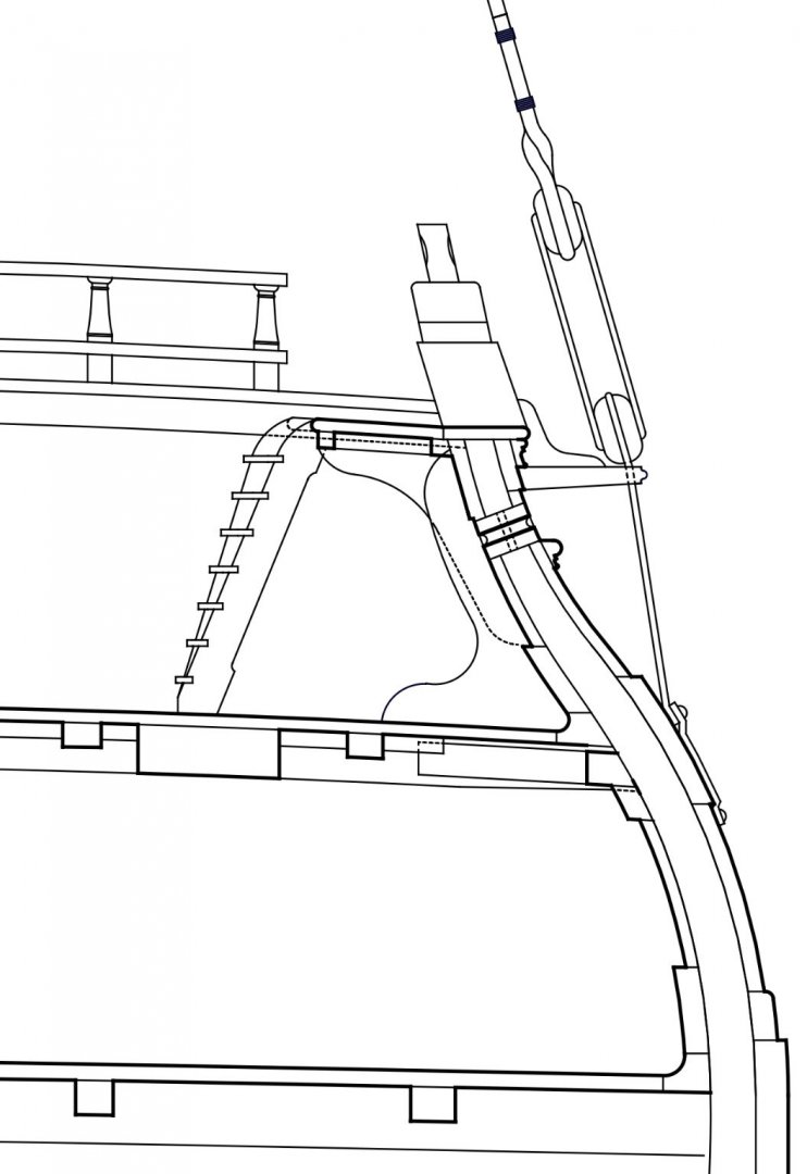
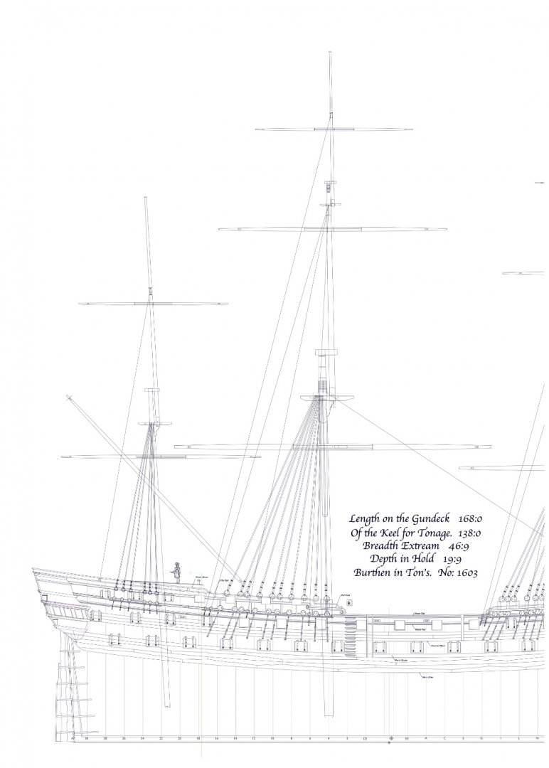
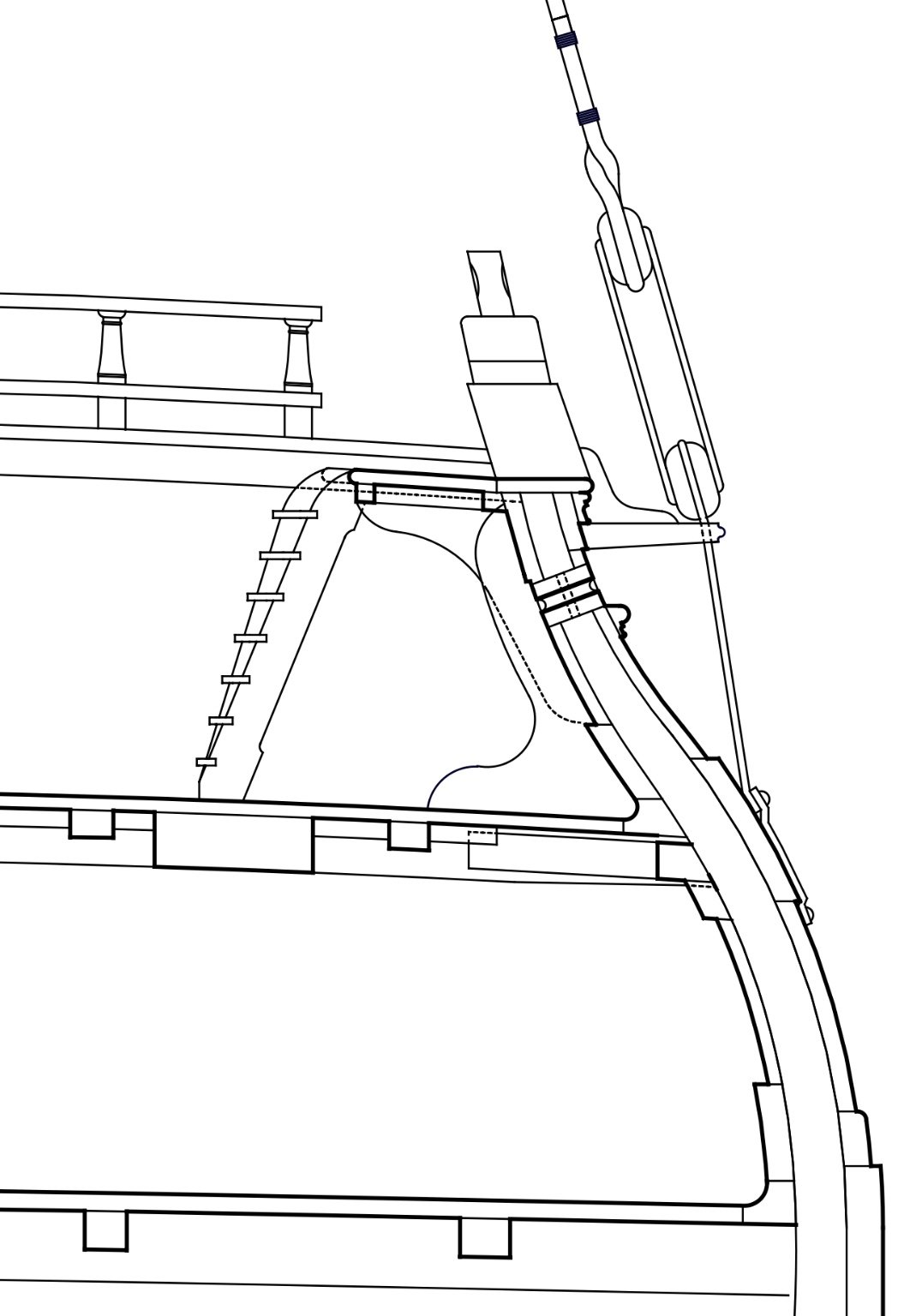
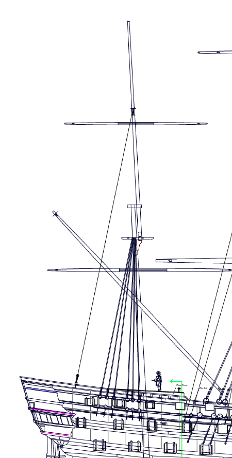
First, as best I can tell, the mizen in this period did not have a topgallant, only a topmast with a pole (see below). So this means that there would only be a backstay to the top of the topmast, correct? And no backstay to a non-existent topgallant. So am I correct in thinking that there is only one backstay coming down to the sides near the mizen channel? The Bellona drawings do not show a deadeye for a backstay on the mizen channels, nor a stool for backstays. I could invent a stool, but it would have only one deadeye, for the mizen topmast backstay. Lees' Masting and Rigging mentions mizen topmast backstays on page 58, and says they either come down to a stool or to a deadeye plate. Might it be a deadeye plate because the drawings do not show a stool?
Second, I see in David Antscherl's Fully Framed model books that there are two rings in eyebolts on each of the fore and main channels. Brian Lavery's Bellona books shows a fore breast backstay on the fore channel, a line seized to the channel, through a block on the backstay, and back down to another seizing on the channel. Would the rings and eyebolts be the fastenings for the breast backstays?
Mark
- GrandpaPhil, mtaylor, Jeronimo and 4 others
-
7
-
Hi everyone,
I have been in and out of the shop for the last long while, attending to other life things, but also really pondering my next steps forward.
After thinking at great length about the issue of when and how to mount the guns, I finally decided that it would be best first to finish all of the outboard work, allowing me to turn the hull on its side for painting, putting in the friezes, etc., then go back to working on internal work including the decks and mounting the guns.
So I have turned my attention to planking again, now facing the fun prospect of making the various mouldings on the upper works. I started looking at how to make the waist rail, to start. It sits against a large tumblehome, so its profile had to be cut at an acute angle to keep the upper surface level.
I used an old hacksaw blade softened with heat, and then tried cutting the profile a couple of different ways. I first tried hand filing, and then for fun I tried milling the profile, sandwiching the metal between two thin pieces of plywood to keep it from flexing as the cutter ball passed by:
I ended up with a combination of hand filing and milling, putting the final shape into an "L" shaped wooden holder creating a fence. Early experiments with letting the cutter run freely without a fence did not work well. It wandered too much.
Because the moulding sits on the angled tumblehome, I decided to pre-angle the moulding blanks by running them through the Byrnes saw using the angled table. I found this to be difficult to set and keep the desired angle, relying solely on tight Allen screws at the mounting. So I made a wooden angle block, clamped under the table. It allows precise setting, and I can return to the exact same angle later on.
I first tried scraping in my small bench vice, trapping the moulding blank between two long vice faces. but this allowed too much vibration, leading to uneven cuts.
I later tried clamping it in my large bench vice, which proved much more stable. I neglected to take a photo of this better arrangement; maybe next time.
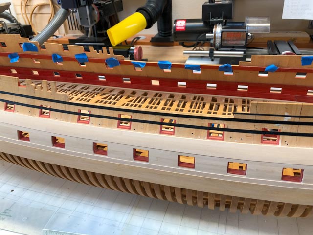
With more confidence in my ability to make good mouldings, I turned to thinking about the remaining planking. I ran 1/8" wide artist's tape (9" to scale, the exact size of the desired mouldings) at points measured from the sheer drawing. This allowed me to confirm the fairness of the runs, especially relative to each other.
I did discover that the hollow at the flair out at the bow at the starboard side was a little too hollow, leading to a slight, undesirable reverse curve on the waist moulding. When I faired this area almost 20 years ago, I did not fully appreciate the direction of the run of the planking itself. So don't tell anyone, but I have had to glue a small filler piece into the hollow, to fair it out to match the port side and clean up the run of the waist moulding. It was only off by less than 1/16", but enough to cause a hollow. All will be covered by the planking!
This all brings me to a big question for those of you who have experience with laying mouldings. I had originally planned to glue the mouldings directly to the frame, butting against it the planking above and below. This, I thought, would allow me to lay the mouldings on a nice curve because I could clamp it down to the faired edge of the planking below. But as I pondered how the mouldings would intersect things like channels, fenders, chesstrees, the various mouldings at the head, and how they would stop at the quarter galleries astern, I began to think it might be easier to apply the mouldings over the planking. But then, how do I keep the mouldings precisely faired and parallel to the planking underneath it? My wood is quite stiff, and does not nicely bend to a smooth curve by itself.
Maybe, a wide batten that could rest on the upper edge of the channel wale, with a faired upper edge, and to which the moulding could be clamped in a vertical direction as well as against the hull?
All for now,
Mark
- JOUFF, GrandpaPhil, dvm27 and 8 others
-
11
-
I agree with the cumulative measuring idea. One way is to measure from a set point out to every frame. Another way is to draw the frames on a jig at the base of the hull (see below). Either way, every time you place a frame, measure where its face ought to be. If the frame needs thinning down, sand the face on sandpaper glued to a sheet of plywood. That keeps it flat, and you can use calipers to check the thickness of each edge to ensure the two faces are parallel.
In my project below, the frames turned out to be varying thicknesses to keep the whole thing the right length as I added to the hull, but the differences are so slight that you never see the discrepancies.
Another subtle opportunity here. In my case, I set a square against the face of the frame. If it was slightly out of square to the base vertically, I used the sandpaper on plywood to gently adjust top or bottom to get everything back into square.
Mark


HMS Bellona 1760 by SJSoane - Scale 1:64 - English 74-gun - as designed
in - Build logs for subjects built 1751 - 1800
Posted
Thanks, JR, for this really helpful look at this issue. Many years ago, when I was first researching the Bellona with only limited references, I convinced myself it would be rigged as the Medway you show, with no crosstrees on the mizen topmast, only an octagonal stop and then a pole. If I see your images correctly, it looks like a single backstay from the octagon to the stool. So there is only one line anchoring to the stool. I am convinced by the stool, by the way; there is no reason we can't have a stool with only one line!
Best wishes,
Mark