HOLIDAY DONATION DRIVE - SUPPORT MSW - DO YOUR PART TO KEEP THIS GREAT FORUM GOING! (Only 20 donations so far - C'mon guys!)
×


kruginmi
-
Posts
629 -
Joined
-
Last visited
Content Type
Profiles
Forums
Gallery
Events
Everything posted by kruginmi
-

How to avoid table saw fuzzies?
kruginmi replied to Keith_W's topic in Modeling tools and Workshop Equipment
Can you provide a pic of the Byrnes setup you are using with one of the carriages nearby? In my experience it all comes down to height of the blade and speed you push the wood through (coupled with ability to clear the debris away from the cut). Mark -
Thanks J for the kind comment. Any help is welcomed over here with this ship! I think I stated earlier my main intent was to learn rigging with this build but I haven't even gotten to that point yet! Maybe this year....(hah hah). Mark
-
Steve, keep the pics coming! I like your decision on tarring the end knots. Really makes the ratlines pop. Something I need to file away for my own use sometime. Just to be above board, I have been recently thinking about a deck house for my Lady Anne and I think I have found it in your build. Permission for a little artistic pull into my build? Mark
- 569 replies
-
- 1
-

-
- shenandoah
- corel
- (and 1 more)
-
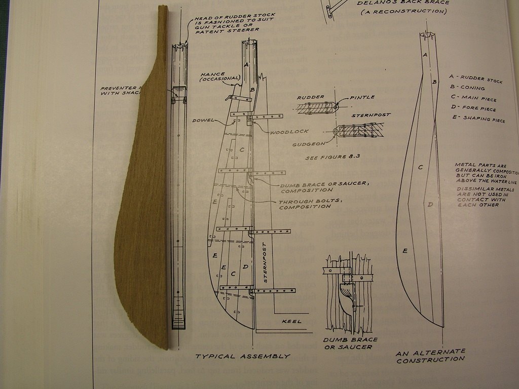
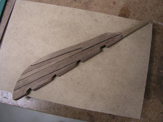
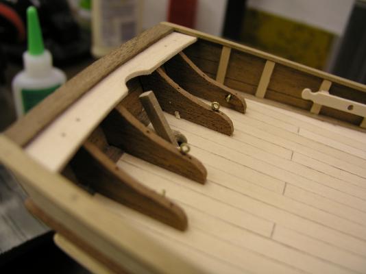
Quick update with an hour in the shipyard tonight. The rudder just kept nagging at me, that I was settling. The bottom line is that I did not have walnut of the width necessary to build the rudder from scratch. Then it hit me, why replace the whole rudder? How bad would it look to laminate boards onto a core? Only one way to find out - try it out. I sanded the existing rudder to a little under a 1/2 of its original width. This accounted for two 1/16" laminates plus a little more to make it more pleasing to my eye. I did this with the spindle sander taking a 1/4 off each side to keep the tiller arm centered. Then using the pattern showed earlier I added the faux planks to each side. After some sanding and.... I am pleasantly surprised that even the edge on look doesn't appear too bad. I am satisfied now. Now for silver soldering some rudder hanging hardware. mark
- 128 replies
-
- 5
-
-
- artesania latina
- Finished
- (and 2 more)
-
Final push to get the lower hold planks in place - the 1/16" basswood ones. I couldn't leave it so close to getting buttoned up so I spent most of the day going back and forth. The old: cut, glue and clamp two planks (one each side), wait to dry, remove and do the next two. Pretty straight forward stuff. I opted to only use planks that traversed the whole cross section. There will be so much stuff down here (eventually) I didn't think anyone would be able to notice any different later. So yet another couple of shots showing the hold: No smooth surface going up the walls here. I realize it would be pretty easy to climb up the walls without any further assist. Still some tidying up to do here and there. Making that mast footing is going to take some time, but that is for another day. Probably need to make some berth deck beams, if not orlop ones to start figuring out bulkheads and the well. The cross section definitely feels pretty solid now! Mark


- 172 replies
-
- 13
-
-
- druid
- sloop of war
- (and 2 more)
-
I am not the expert on these things, but my research has shown what I have done is consistent with 'most' larger ships. I do believe a small notch is sometimes present through the frames at the very bottom (close to the external planks) but given the accessibility and lack of regular maintenance that would probably plug pretty quickly with debris. With all this work on structure and strength they probably need to keep the frames intact at this point. The limber boards will go into the limber strake slot and lean up against the keel providing a passage to allow any water that can travel to to the center hull where the elm pumps are located (these will be located in this cross section). On top of this will be all the ballast and cargo (thus the limited accessibility). You also have the space between the keelson and keel which would allow water to flow from port to starboard. Higher up, between the berth and gun decks will be a ventilation space where a gap in the internal planks will be present, exposing the frames. This is for the evaporation and drying out of the lower frame areas. This build is a learning exercise just for questions like that for me so I appreciate the query. Anybody else able to add to the discussion? Mark
- 172 replies
-
- 2
-
-
- druid
- sloop of war
- (and 2 more)
-
I really like that presentation. Great job! mark
- 625 replies
-
- 4
-
-
- bounty launch
- model shipways
- (and 1 more)
-
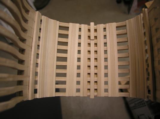
Thanks for all the likes and looks. While the wind howls outside and the temp reads below zero I set my sights on getting the middle stuff (my term) set in the lower hold. This is 3/32" basswood strips primarily on either side of the thickstuff (1/8" basswood). Finally I can call it good. Next up is the regular planking (1/16" basswood). It shouldn't take too long. When I started this process of the internal planking I thought the big question was going to be whether to plank up from the keelson or down from the berth deck clamp. The reality was a bunch of jumping around to set the thickstuff and now I am left with the filler. A lot more respect for trying to accurately plank the internal hull of a complete hull, regardless of scale! Mark
- 172 replies
-
- 10
-
-
- druid
- sloop of war
- (and 2 more)
-
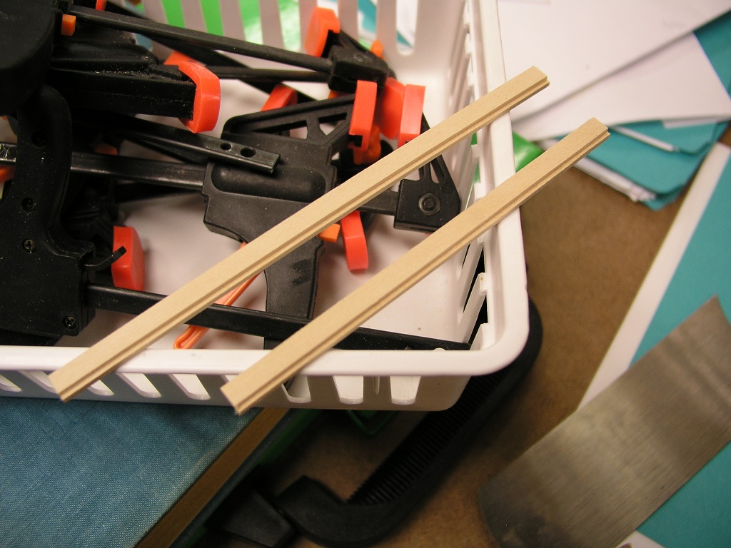
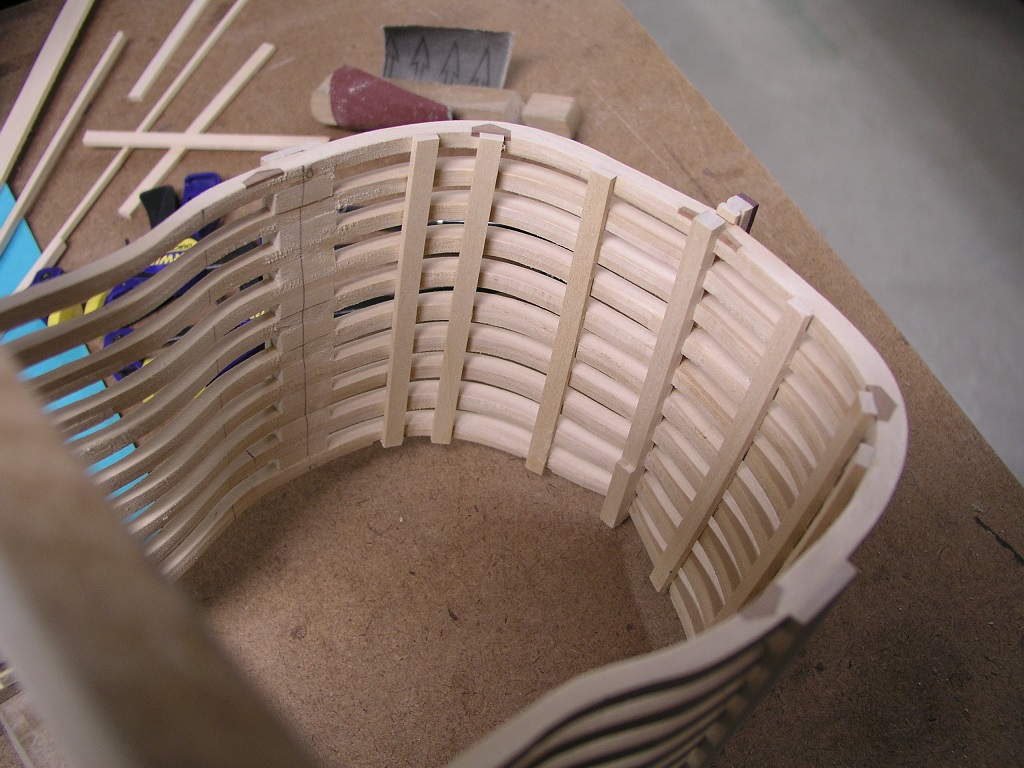
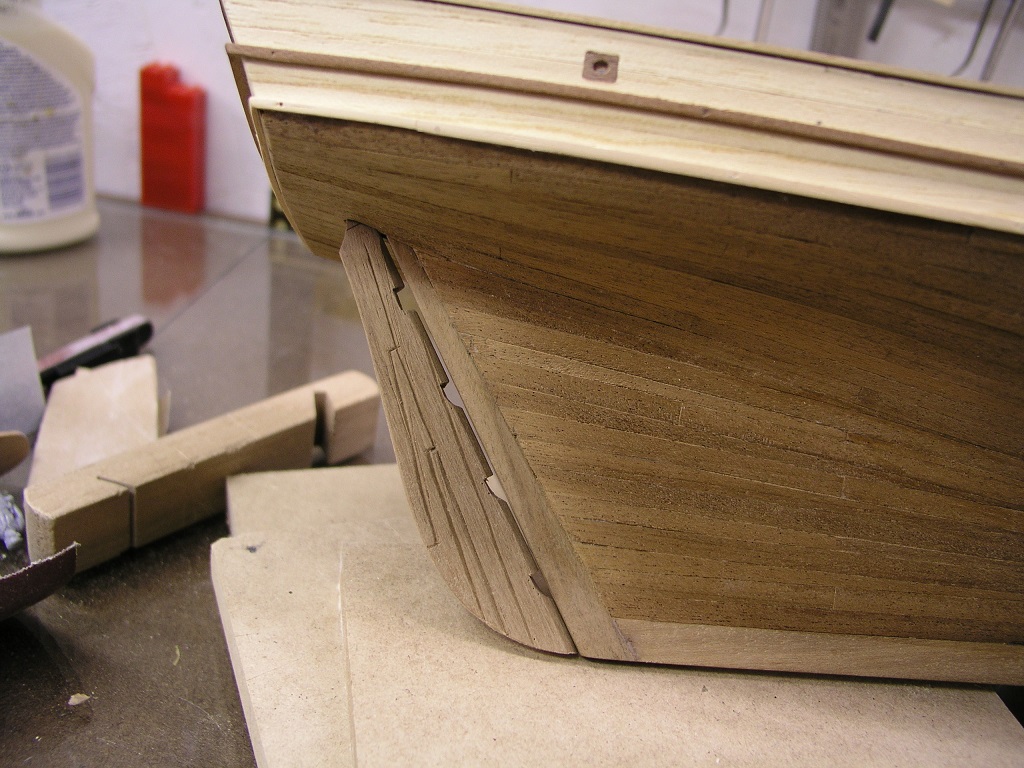
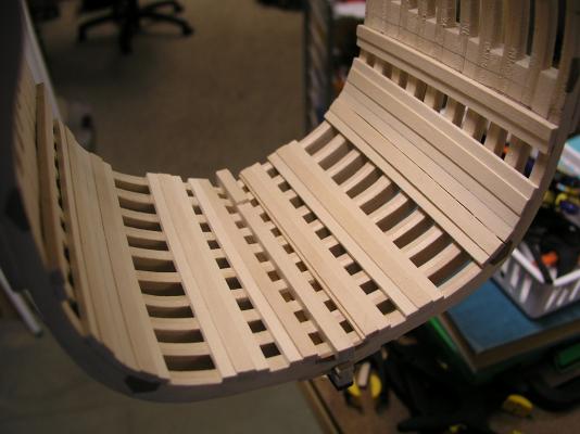
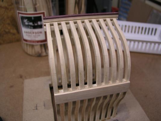
Another update in the evolution of the Druid-X, this time focusing on the garboard and limber strakes. For the limber strakes I am still using the thickstuff stock (1/8"). These require a slot to allow the limber boards to fit in between this and the keelson. Using the Byrnes saw I quickly had my raw stock. Using a spacer piece of wood to insure consistent separation from the keelson I glued in both limber strakes. Everything ended up looking fit and proper. A good result. As a companion it was time to put on the first regular planks on the hull (1/16"). The natural choice was the garboard strake - and in fact I did one better, the garboard strake plus one each side. These were again cut rectangular with no specific shaping. The rest of the planking will be custom fit and cut. The ends of the planks aren't perfectly flush with the aft and fore frames. I am resisting the urge to sand them into all the outside and inside planks are attached to avoid screwing up the face of the frames - as much. Next up is the middle stuff (my term - hah hah). Some 3/32" stuff that abuts a lot of the thickstuff prior to the regular planking. I also want to get the berth deck clamp in. It wont be too long before the lower hold is sealed in. Mark


- 172 replies
-
- 12
-
-
- druid
- sloop of war
- (and 2 more)
-
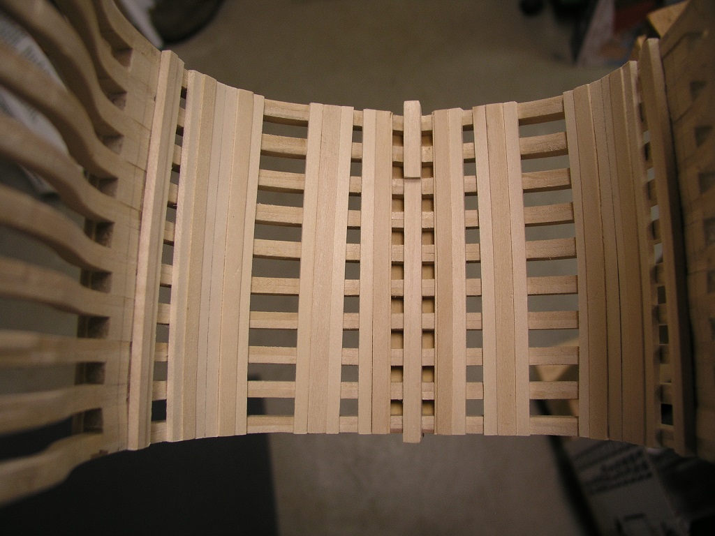
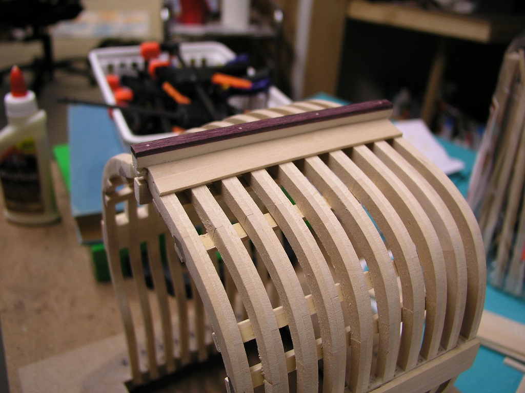
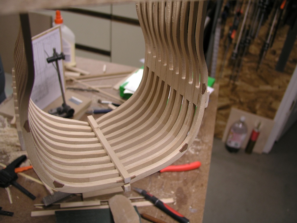
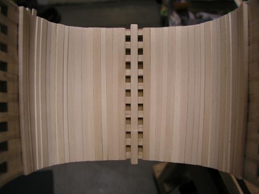
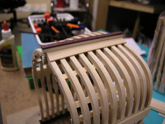
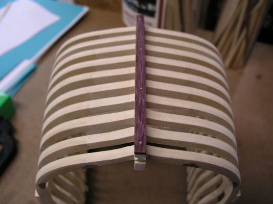
Onto the thickstuff. I have learned over and over that reading and studying only take you so far - it is the creation of an accurate 3D model that really brings things to life. And this was reinforced again here. I had never really associated the thickstuff planks with anything other than longitudinal support. As I once again read over the available material it finally clicked: The thickstuff planks correspond with the futtock joins of the frames. This had escaped me primarily because half of these joins were never visible being on the other side of the frame. It makes perfect sense and brings additional order. Now I understand the ramifications of how I defined the frame joins at the beginning. At first glance I would say my frames have their opposing joins too close. However, I will invoke my American made cargo ship edict which lets me bypass all normal building standards. I have learned something I did not know before. The hull is at its widest near the forward part of this cross section and slightly reduced near the aft. I decided not to reflect this change in the thickstuff planks themselves, keeping them straight and rectangular. The lines penciled on the internal hull represent the berth and gun deck locations. Next up is the limber and garboard strakes. Stay Building my Friends, mark


- 172 replies
-
- 15
-
-
- druid
- sloop of war
- (and 2 more)
-
I also agree with the black jib stay. Awesome job Steve! Mark
-
My advice to you would be to consider another ship in the bottle kit - you seem to have a knack for it! Mark
-
The task for the day was a Keel Rabbet. The difference for me is that this rabbet is more than for looks. I actually need a garboard strake to fit into the rabbet and given the cross section you get to view the results on two ends. So....off I went. I did drill through the keel, the frames and partway through the keelson at each frame. Four of these holes where then drilled through the false keel. Adding trunnels through the whole assembly made it very stiff. I am pretty happy with the results. Now I get to start working on stuff that will for the most part be seen! mark


- 172 replies
-
- 15
-
-
- druid
- sloop of war
- (and 2 more)
-
If it helps I found the third kit I have (which includes sails). Next time in the area i will give it to you whole.
- 42 replies
-
- 2
-
-
- Constitution
- Revell
- (and 1 more)
-
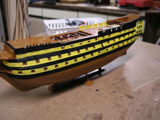
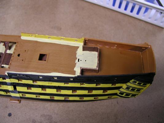
Slowly slogging forward. My son has a lot of stuff going on so I have to wait and not get too far ahead. During a slow evening while watching my four year old I hand painted the hull on the port side. This is hand painted because that is what he is able to do, no airbrushing or spray painting here. I was slightly surprised that the hull follows the true planking for the most part, meaning their are no specific guide lines for the yellow bands. You basically have the gun ports for alignment. I had started with acrylics but for the hull switched to enamels. The acrylics required too many coats for a solid coat of paint and the bands were too much to keep the straight lines going multiple times over. I did affix the rear bulkheads underneath the quarter deck and paint a first coat of deck color around the outside edges. Cannon carriages will be next for plastic to plastic adhesion prior to painting the rest of the deck. The guide lines for the bulkheads do not totally align with the bulkheads so be careful if you attempt this kit. I assembled the walls off ship and glued to the deck as a unit. Probably a 1/4 inch or so between the rear bulkhead and its associated alignment ledge. One big issue I had to resolve was how to paint the stern windows. There is a slightly raised boundary but again, a 10 year old. The solution I finally arrived at was to use a fine tip pen. Yes, the color will probably fade but there is a chance Peter will affect something that resembles a window. These windows are obviously plentiful on the stern. I also opted to avoid painting individual pillars and just painted the section yellow. I do have copper paint for the bottom. My review of the kit: These are old molds but still have a lot of detail that comes out. If you are looking for every seam to be seamless and be an accurate representation of the Victory, this is probably not the model for you. If you are looking for a fun project that people will recognize as the Victory then have some fun. I look forward to the yard arms (curved and bent in all sort of angles). No idea of how I will get them usable, but with a little heat I am hoping for the best. Stay Building my Friends, Mark
-
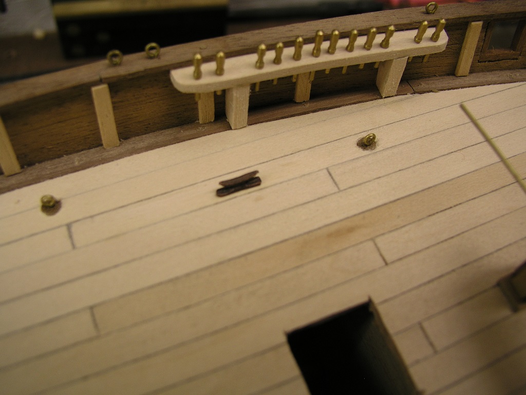
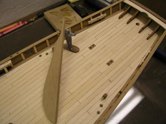
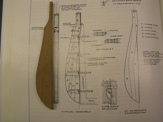
I have worked my way through affixing all 50+ eyebolts. About half of those were put in by the plugs described earlier. Towards the stern two ring bolts each side were too close together for individual plugs so I cut a rectangular one that encompassed both bolts. So the next step was to move on to the rudder. I keep reminding myself that the point of this build was to provide a basis for learning rigging techniques, that the main hull was supposed to be out of the box. So much for that plan. The rudder provided by the kit was a large chunk of walnut cut to the shape of a rudder. My first step was to look in Crother's book on clipper ship rudders and it was seen this was a pretty good form: However, more than one chunk of wood was used. It is interesting to note that some of the beams drawn out do taper to a sharp point, the first instance where I have seen this done on an external hull in actual practice. Trying to keep this build going forward (and get to the rigging) I penciled in the beam lines into the kit rudder and scraped them to provide a resemblance of the separate pieces. Another challenge that presented itself was the tiller arm. Looking on deck with the rudder now in place, the attachment of the tiller is pretty far back towards the back rail. I will have to think this through on how to work this. I always have the option of making a rudder box obscuring the whole thing. Stay Building my Friends, Mark


- 128 replies
-
- 6
-
-
- artesania latina
- Finished
- (and 2 more)
-
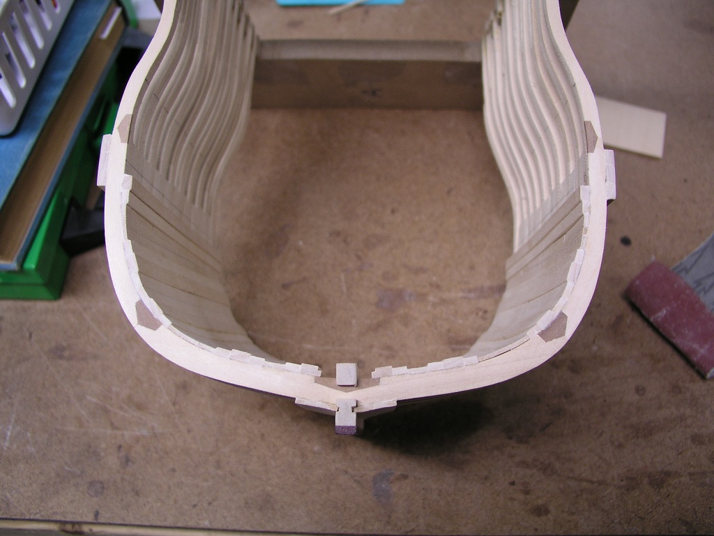
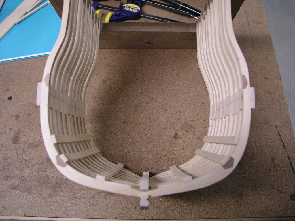
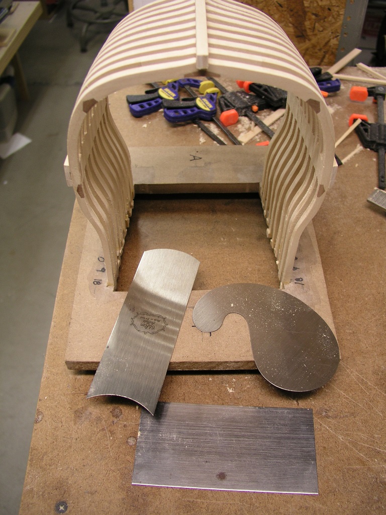
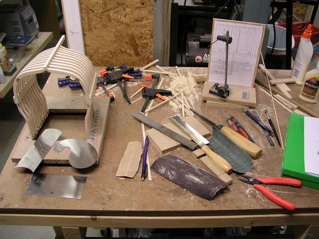
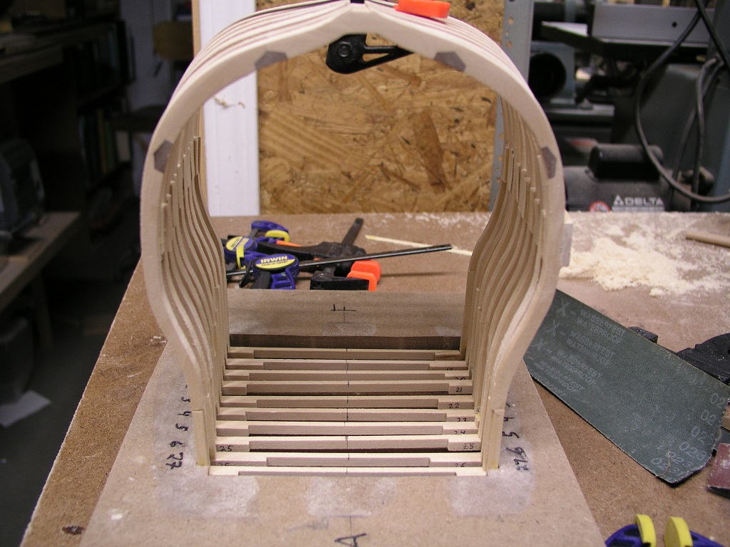
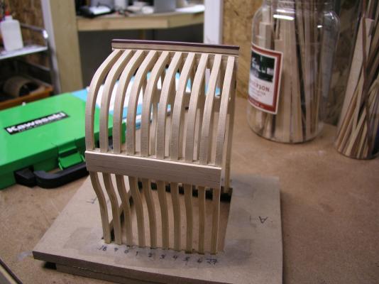
It has been some banner time in the workshop the last couple of days. I was boresighted on getting past the frames so this afternoon I was back at it, this time for the internal fairing. To borrow a phrase "Say hello to my little friends" Cabinet scrapers are very effective in removing wood on the internal hull. Supplement that with some final sanding and you can do a lot without a lot of sawdust flying about. More evidence of my activity is the current state of my rough worktable: Definitely needs some cleanup tomorrow, but a tidy workshop does not show progress! At the end of the day I can stand back and look at my hull with keel and keelson on (but not yet attached). Still need another hour or so of refinement but I am happy with the progress and I can see the finish for this part of the project: Tomorrow probably switch to the Lady Anne for awhile. Stay Building My Friends, Mark


- 172 replies
-
- 12
-
-
- druid
- sloop of war
- (and 2 more)
-
Thanks Mark and Greg, you spend so much time thinking and pondering yet let something pretty obvious looking back at it escape you. These frames are taking time (perhaps too much) and maybe I am giving too many photos. I believe the Hahn drawings have some issues at this part of Druid (as I think I have stated before). Much more checking on mirror images in the future for me. Still workable but I have focused on fairing below the wales and now I am resetting the top timbers (usually by millimeters) into the jig to allow better alignment above the wales (lower part now fixed). Hopefully on the home stretch for this part of the build. Mark
- 172 replies
-
- 2
-
-
- druid
- sloop of war
- (and 2 more)
-
One note I can add is that you never know where you are going to get bit. When overlaying the wale template on the cross section I found that the cross section was about a 1/8" too short. This puzzled me. Measuring the base and keel showed correct widths. So....the spacers used were a bit too small. Visually it was invisible and 'wouldn't' have affected much since the whole hull was not involved. However very quickly I knew I had to do something and this was the only time available for fixing it. I ended up cutting through the first and last spacers on both side and added 1/16" spacers into each. Glued it all up - solution done. Everything measures up. There is always something. -Mark
- 172 replies
-
- 2
-
-
- druid
- sloop of war
- (and 2 more)
-
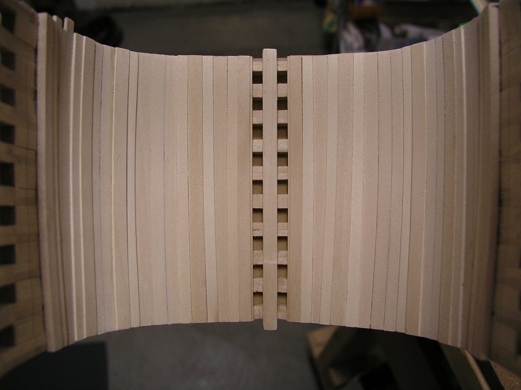
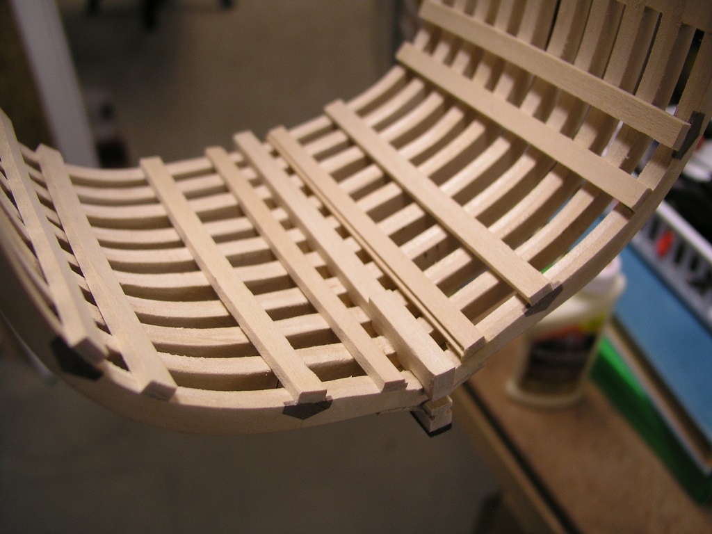
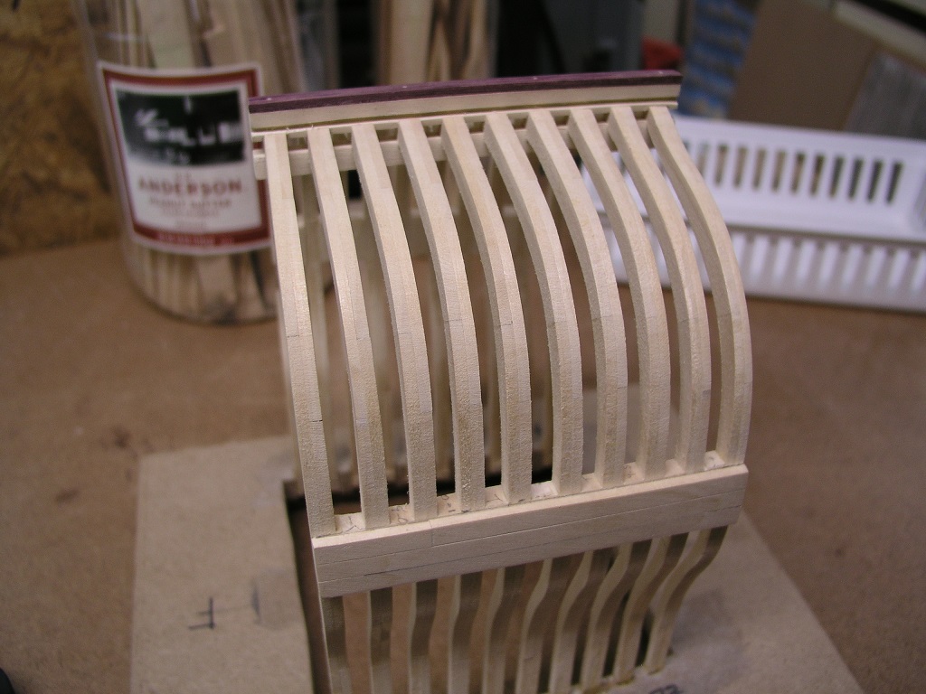
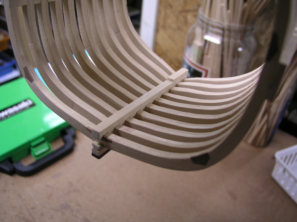
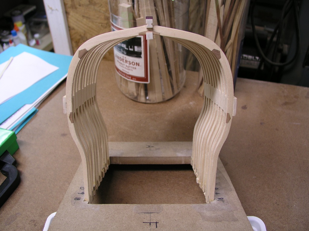
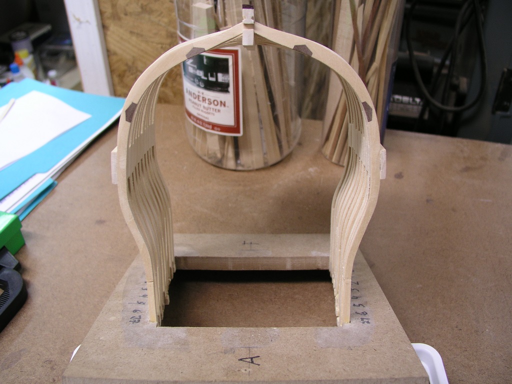
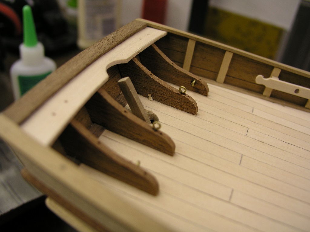
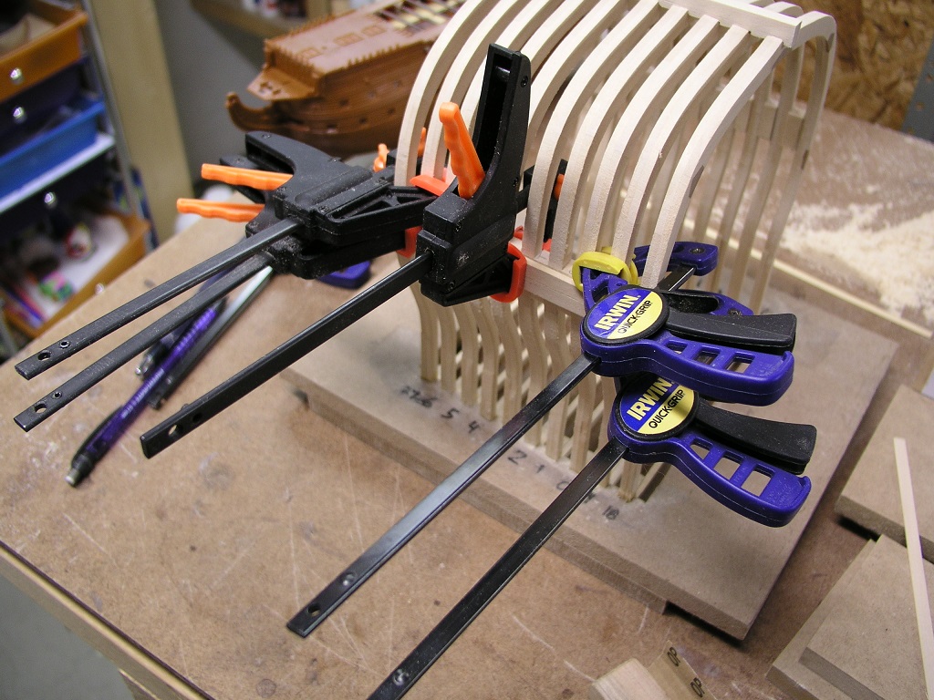
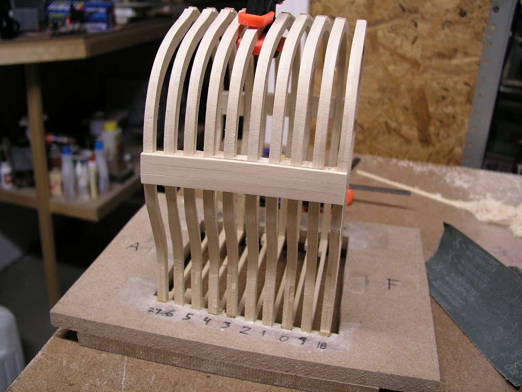
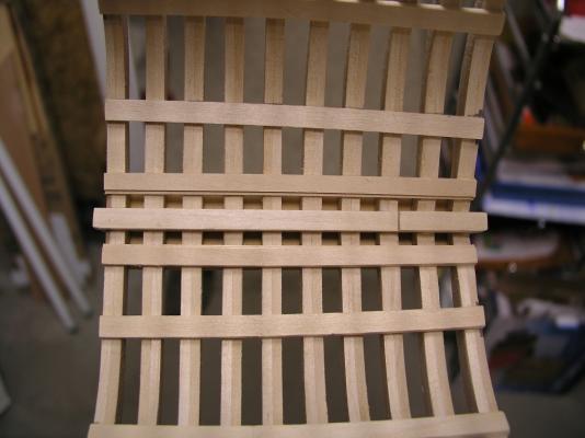
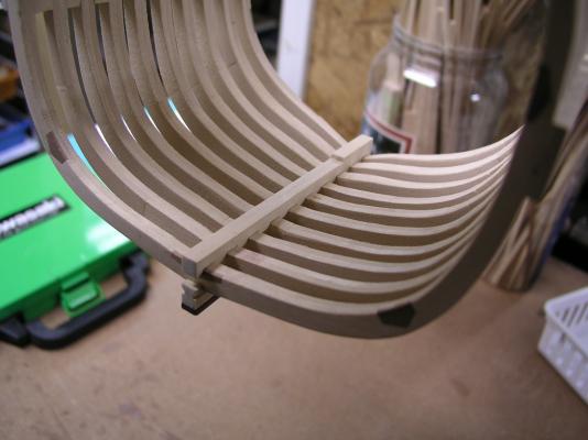
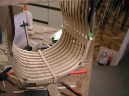
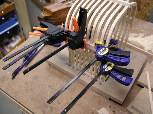
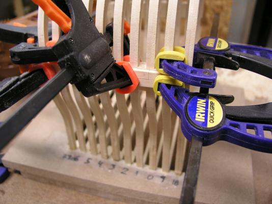
Thanks everyone for stopping by. Tonight was another big night for Druid-X: I affixed the first plank. I am putting the wales on at this time to provide greater longitudinal strength. I traced the wale pattern off of the plans and defined three plank widths. The curvature of the wales was transferred to a piece of 1/8" thick basswood (double the 1/16" plank width) and this pattern cut / sanded out. After I was satisfied with the curve I used dividers to define the width of one plank and also cut and sanded this out. This continued for all three planks. The middle plank was to span entirely across the cross section, the upper and lower ones being jointed three frames in (different sides). I affixed the middle plank first given it was the easiest one. The following pic shows the top one being put on: I now laugh looking at this. It was with the click of the shutter that I made a mental note to insure the joint in the lower was made on the opposite side. The opposite side of.the.joint.that.I.had.forgot.to.put.in. The glue sets fast but I was able to pry off the top plank without too much damage, cut the joint and re-attach. Here is a shot of what it was supposed to look like originally: I added the third plank then sanded the edges flush with the frames. In this pic you can see the face on view and also the chocks completed on the opposite side of the cross section. Trying to accomplish a little bit with every hour - Stay Building my Friends, Mark


- 172 replies
-
- 8
-
-
- druid
- sloop of war
- (and 2 more)
-
Thanks Eamonn. I am trying to focus on getting projects done (without losing the fun). It is time this one is finished up. Next up is a totally new cabin entry way. Mark
- 128 replies
-
- 1
-
-
- artesania latina
- Finished
- (and 2 more)
-
Thanks Steve for stopping by! The only kit original portion is the hull form. Everything else has been scratch from me to produce a replica of a Baltimore Clipper. The windlass was a composite from views / plans I saw on the web and this site that I liked. Since this is not based on a specific ship but a class of ships I have free range to do what appeals to me (thus the fun build part). The rigging is based on the Pride of Baltimore implementation (as on the real ship). Lots of fun in my future. Mark
-
Beautiful job, Nils. I don't know when you sleep..... Mark
-
As I can fully attest, she will be ready to go when you are. This is not a race - you said it best it is for enjoyment. Get Healthy! Best Wishes Mark
-
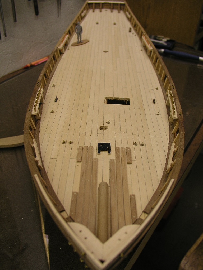
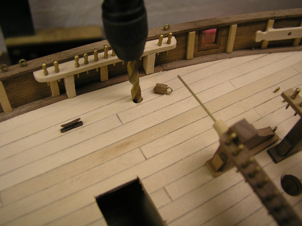
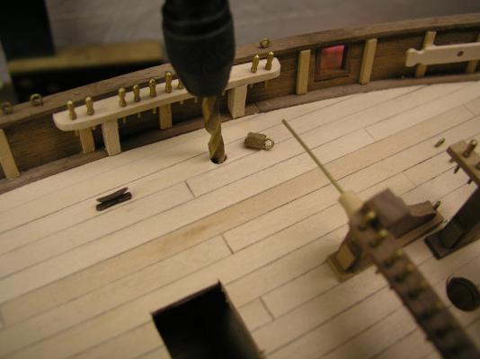
My Lady Anne has sat patiently but today was the day I listened to her call. I am pretty close to rigging so that will be a good companion to the Druid-X. I dusted her off and re-oriented myself to where I left off. The last item I had done was position the eyebolts. This ship is to be rigged as an operating clipper ship, the Pride of Baltimore II is the plans I am basing this off of. Lots more blocks, eyebolts and lines to lay than what the original kit intended. Pretty much nothing left of the original kit Harvey at this level. I had concerns with how well the eyebolts would stay simply glued in place on the deck. I have looked at the various options for affixing them but arrived at a solution for the ones on the deck: I will add plugs of walnut for a little more pop and the ability to clench the bottom of the eyebolts themselves. This was a simple matter of finding an available walnut dowel that I thought correctly sized and drilling a companion hole for the dowel to fit in. The dowel itself was drilled through for the eyebolt to pass and clenched down. There are over 20 eyebolts to do but that shouldn't take too long. After dry a couple swipes with some sandpaper should clean any residue up. This is a fun build that I do what I want. I will finish her this year. I need to really think about what finish to use. Suggestions are welcomed. Mark


- 128 replies
-
- 8
-
-
- artesania latina
- Finished
- (and 2 more)