

glbarlow
-
Posts
4,015 -
Joined
-
Last visited
Content Type
Profiles
Forums
Gallery
Events
Posts posted by glbarlow
-
-
As most everyone says there is no saw but the Byrnes saw. He has zero clearance inserts very cheap, no reason to make one. He has a 220v version and many Europeans have one. He and his wife are a two person business. He can’t quickly respond to everyone, he spends most of his days making great saws.
The extended fence is a must, for me the micrometer I have and never use. I also haven’t needed the zero clearance insert I bought and have ripped and cut everything for my Cheerful without one. I had it in and took it off. Jim’s blade selections are the best there are for his saw. He carefully researched them. You don’t need a bunch of blades, the 30 kerf slitting blade is all I’ve used for Cheerful. Maybe a spare one of those. Plus the big one that comes with it.
You don’t need an adapter if you use his blades, which you should. I can’t imagine the need for a wider table. I’ve had my saw for 12 years and that need never came up.
The best accessory other than the extended fence and the extended mitre gauge rail is the sliding table. When I’m not ripping planks I use it a lot, it’s easy to put on and take off. I never knew I needed it until I got it. Cutting the hatch covers for Cheerful was a piece of cake with it.
It may cost more but it’s worth every cent. Mine has run faithfully for a long time. The slitting blade so far is the only “part” I’ve replaced.
- JpR62, Bob Cleek, thibaultron and 2 others
-
 5
5
-
3 minutes ago, Rustyj said:
great example of your fine workmanship!
Thanks Rusty, I appreciate your saying so!
-
-
-
The rigging looks great as does the model. When I get to Flirt your log will be my constant reference.
Let’s make sure our wives don’t learn how much we’ve influenced each other’s tool purchases.
btw, it’s Cheerful, not Alert😁
-
-
4 minutes ago, JpR62 said:
again a lot of information
Thank you. That is my hope. Yours is coming along great!
-
17 minutes ago, DelF said:
look for a cuticle cutter...
Thank you for the comment. I’m sure there’s an equivalent on Amazon UK. 😊
- Ryland Craze and DelF
-
1
-
 1
1
-
The Masting & Rigging Begins
A new stage of building has begun. With the hull complete its time for the masting and rigging, beginning with the bowsprit. I kind of enjoy this part of the model, and once again (he said again), Cheerful is taking me into new territory.
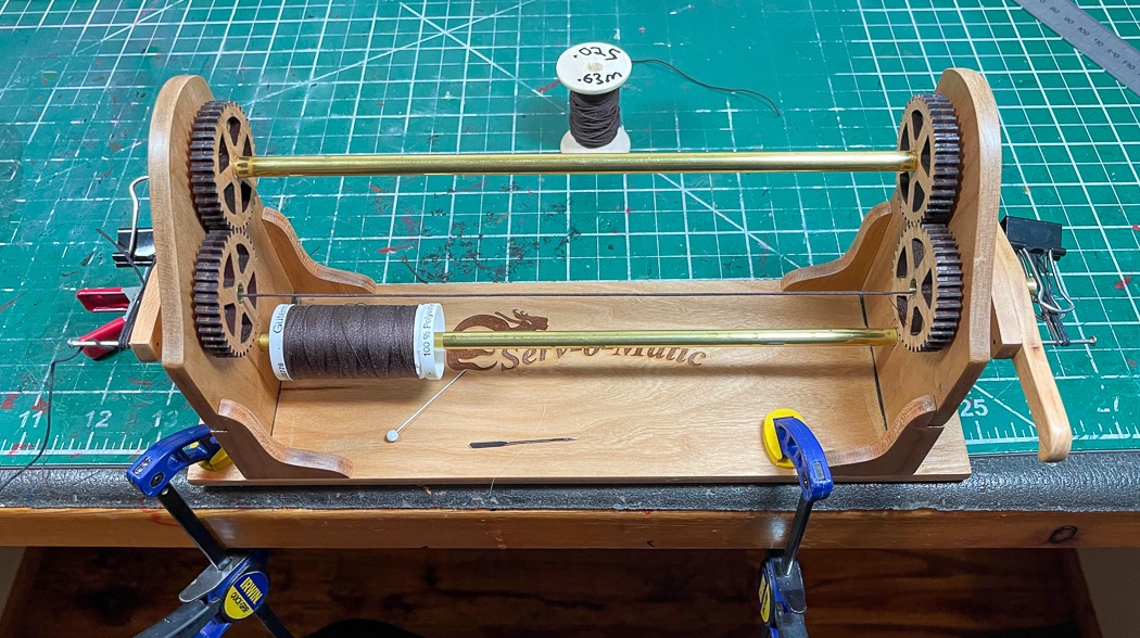
The bowsprit bobstay and guys, or as someone with my level of nautical knowledge calls them, the bow stringy things, require both served line and thimbles. So there was a pause while I assembled the Syren Serv-O-Matic I’d purchased a long while ago. It was time consuming and not at all fun removing all the char from each piece, but Chuck is right in the instructions to encourage us to do so. It does look much better once done and coated with WOP. Now to figure out how to use it, I thought it would be more complicated than the simple instructions explain. Turns out it wasn’t - its the perfect machine to serve rope quickly and easily. My first effort, which I thought would be practice, was good enough to use. It takes no more effort than turning the crank and a steady hold on the thread.
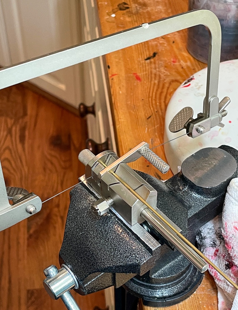
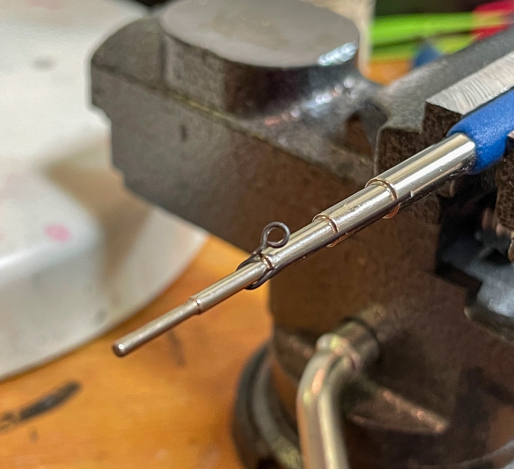
Next up are the thimbles. I found this nifty brass tube cutter at Rio Grande Jewelery tube cutter which has a number of handy tools for modelers. It comes with a handle, I removed that and mounted in on my vise. It proved to be an excellent way to quickly generate short lengths of very thin brass tube with a neat cut. Just set the length with the screw guide, hold the lever down with one finger, place the jig saw in the slot and cut. My $17 (including a bunch of blades) Amazon jig saw proved its quality and value once again, cutting as many as I wanted without fail or issue.
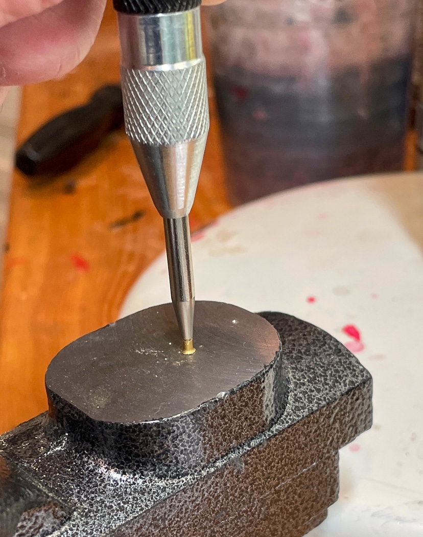
I found (thanks to @DelF ) that a spring loaded punch is much more effective for me at consistently generating an even “fold” on the both sides of the brass tube to create the thimble. While of course a hammer and regular punch work fine, I more often than not crushed one side or the other - why practice my hammering skills when the $9 spring loaded version (Amazon) does the job. After creating a number of them in different sizes I blacked them using my standard process.
I have plenty of commercial hooks, eyelets, and rings - and I’m not using any of them. In fact I pulled off the ones I had placed earlier (down the center of the deck) and replaced them with home made versions, mostly of 24 gauge black wire. The heft of these on a 1:48 scale model is noticeable. After some practice and a bit of wasted wire, I now have my own way of knocking out all the eyelets, rings, and hooks I need for Cheerful. It was good I did because the thimbles require a hook with a larger eyelet to connect the hook to the rope.
I learned my rigging technique from Bob Hunt’s practicums, his AVS was my first model many years ago. The “fishing lure” method of seizing has served me well, but I thought I’d look at other methods and did a little research. I came to the conclusion that while there are in fact many ways to seize lines and strop blocks, after experimenting with a few of them I’m content to continue with the one that I’ve been using. With two additions: First, thanks again to Derek, in some instances I’ll use thin fly tying line and in others I’ll continue to use 50wt Gutterman poly thread. My only issue with the fishing lure method has been the small thread ends that were left despite my using high quality Gingher embroidery scissors. Second, thanks to @Ryland Craze I now have the answer to that issue by using extremely sharp and close cuticle cutters, my newest ‘tool’ investment (again from my friend Amazon). They are so flush cutting and sharp they can also cut the wood of the block, which I did and consequently had to replace, so care is needed. I also vary the use of watered down white glue, hypo-cement, and CA depending on the situation. I'm comfortable with each, they each have their pros and cons, why fixate on just one or the other.
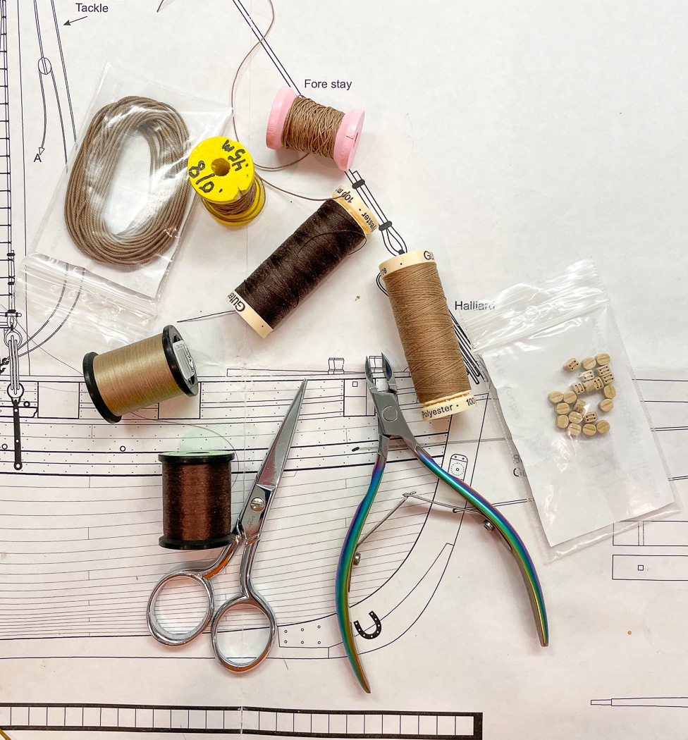
Finally, I have a bunch of empty thread spools to transfer Chucks now historical rope, marked with the size. Not sure what I’ll do when these go empty for the last time, maybe a Rope Rocket in my future, but not for this model - I have what I need.
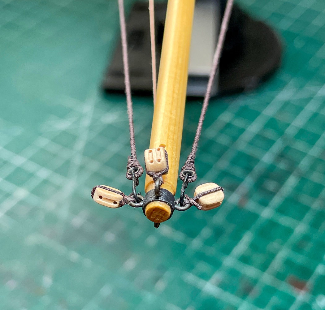
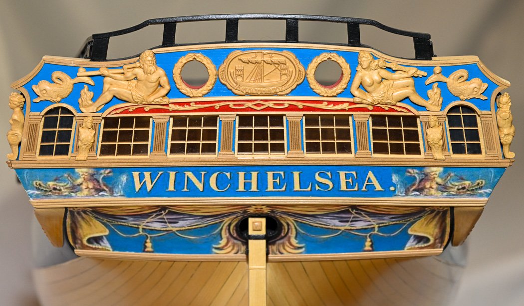
And off I went. The bowsprit collar is shrink wrap plastic (but I also use black card or black masking tape again depending on the situation). The rings in this case are made from 22 gauge black wire for some extra heft and of course a little (very little) weathering powder brushed on. The blocks are seized to the hooks with fly fishing line while the served rope is seized with 50wt poly thread. The thimbles are from 1.6mm thin brass tube (yes, Amazon). The hooks have larger eyelets to accommodate the thimbles. Of note these where done before my “discovery’ of cuticle cutters, but I didn’t want to go in there after the fact for fear of cutting off more than I wanted to cut in such close quarters. This is one of this macro hi-res photo things. I didn’t even notice excess thread until I looked at the photo for this log entry.

Here’s the bowsprit end of the bobstay tackle and guys, naturally I’m using blocks from Syren.
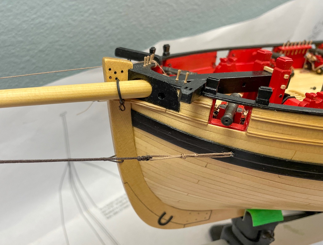
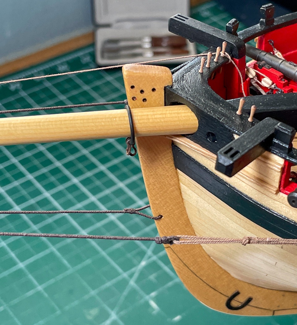
And the bow side view of the same. The bobstay is belayed to its pin, but loosely. Like most I don’t tension the lines completely until later. The guy lashing took some experimentation (it was replaced more than once) and research, none of which was definitive. I learned many different techniques were used both by modelers and on the actual ships. In the end I opted to seize the line at the bow eyelet and tie it off at the center after two loops through the guy thimble and seize the running end past the knot (essentially a sheeps bend). And…I remembered to put on the traveler before the blocks, so it will just hang there a while.
Next I turn my attention to the mast. Thanks for stopping by, the likes and especially the comments are always welcomed and appreciated.
-
Your workmanship is topped by your knowledge of all things nautical. Always an enlightening story to read.
-
5 hours ago, JpR62 said:
width of the planks at the stern
I didn’t taper any planks at the stern. The model is so well designed I had a perfect fit with using the standard width around the tricky curve there.
5 hours ago, JpR62 said:paint the outside of the counter
I did, but I don’t think anything drives you to at this point. The key is to have the back end flush with the counter before painting either the counter or the fashion pieces, since they are painted a different color.
5 hours ago, JpR62 said:wait until I have installed my first 2 rows of planks before sanding them
I think my log discussed how the fashion pieces, square tuck, counter, and planking all come together, and ultimately a trim piece later. Up to you though how to make that happen. Matching them to the wales is critical.
5 hours ago, JpR62 said:perfect replicas of the plan.
I had to improvise to get a fit I was happy with. It becomes what works for you.
-
Just pull it through a stick of bees wax. One stick will last a life time of model building. It eliminates fuzz and helps the rope hang better. It’s all you need, I’ve used it for over a decade without issue.
- mtaylor, thibaultron, Tim Moore and 4 others
-
7
-
You’re moving quite quickly, I’m enjoying your progress as I have this on my shelf to build as well. Excellent work and insights as always.
-
18 hours ago, glennard2523 said:
Excellent job Glenn!
Thank you...oh, you mean the UK Glenn😂🤣
- Glenn-UK, Edwardkenway, DelF and 1 other
-
 4
4
-
Not sure I buy that comment. The boxes on the shelves are all labeled. I don’t even have any sanding stick sponges🤣😂
- Canute, clearway and Old Collingwood
-
3
-
Nice work. Brings back memories.
- JpR62, Saburo and FriedClams
-
3
-
54 minutes ago, Edwardkenway said:
museum or discerning collection
Thank you for saying so, but the collection will only be mine I’m sure. I doubt I could part with it after being so long together with her.
-
1 hour ago, garthog said:
What a beautiful job! Why go further?
Thanks Garthog! There’s still more fun to be had and more things to do for the first time, I can’t stop now😁
-
1 hour ago, DBorgens said:
I look forward to your masking and rigging
Thank you! Me too 🙂
-
2 hours ago, Chuck said:
It shows how careful and attentive to craftsmanship you have been.
Thank you Chuck. I also love the color and tone of the yellow cedar. My focus on detail and willingness to do it over until I get it right is a tribute to your elegant design, instructions, and guidance.
-
26 minutes ago, marktiedens said:
Very nice!!
I appreciate your saying so.
-
2 hours ago, WalrusGuy said:
enjoyed the photos!
Thank you!
-
2 hours ago, DelF said:
achieved such a crisp, clean finish on all your work
Thanks Derek. I’ve tossed and replaced so many things all the way back to planking I feel like I’ve built it twice.
-
1 hour ago, drjeckl said:
tried the look of a train tackle for the gun carriages?
I thought about it and replaced the ones seen in the photo with 24 guage wire versions but from clean deck it would go to cluttered deck in my opinion, especially with the rigging to come.
which table saw to get??
in Modeling tools and Workshop Equipment
Posted
I see the point. I also go back and forth, it doesn’t take me but a minute to loosen two Allen screws and lift it off. At any rate it’s good there is an option. I know I’ve never cut anything that would need that extra width.