

glbarlow
-
Posts
3,855 -
Joined
-
Last visited
Content Type
Profiles
Forums
Gallery
Events
Posts posted by glbarlow
-
-
31 minutes ago, bartley said:
we must credit Chuck Passarro
Yes, while it’s my workmanship, as I frequently do in my build log all due credit goes to Chuck. As I also noted I was initially a little reluctant to use weathering powder now I weather everything simulating metal.
While this discussion has been focused on wire, blocks can be seized with rope and the loop created by seizing it on a drill bit then the resulting loop stiffened with CA. Easier to work with and though it will give, probably about the same as 34 gauge wire though I’ve never compared them.
-
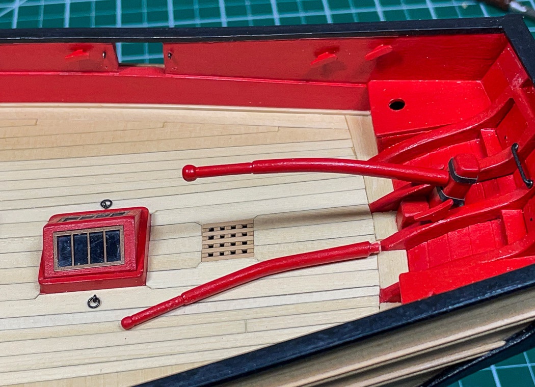
The Boom Crutches
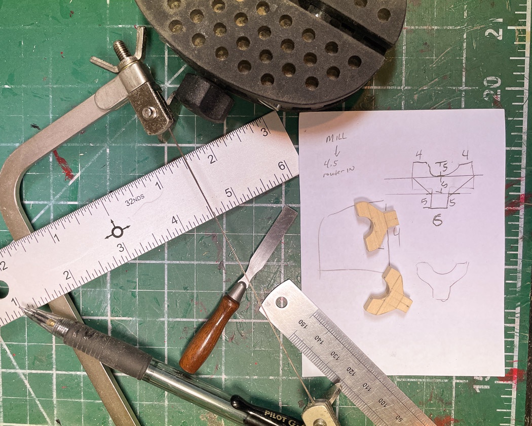
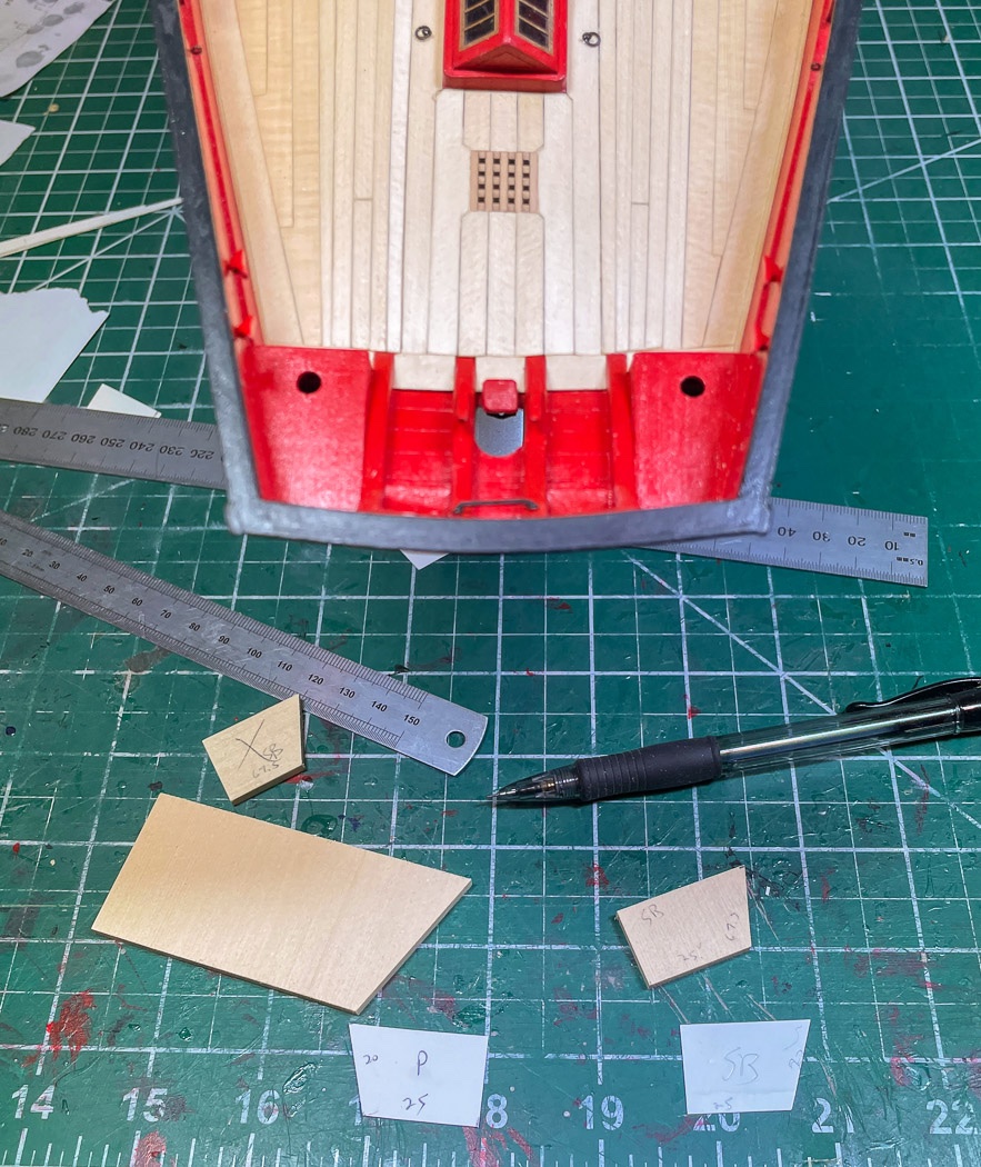
I had to sort through how to get started on the boom crutches, the monograph picks up with how to approach the angles, which is essential to the process, but has the basic crutch already made, I had to figure out how to get to that point. I started with some rectangular blanks of ¼ sheet cut a little larger than the finished width and height then, with my pencil and paper constructed a series of measurements and lines to work from to create the initial Y. I suppose some can free-hand such things, I cannot. I wanted a precise beginning to get me to a precise end.
I used a router bit on the mill for the half circle and the jewelers saw with the blanks in my small vise to cut out a starting point. As Chuck points out these need to be extra thick, the ¼ barely covers it. The reason is distinct angles that have to be accounted for and the resulting sanding and cutting to get those. The monograph starts with the side, I found it easier after a couple of false starts to start with the back angle first, then the side then the front. The two remaining angles, the top and the turn in towards the mast are best done after mounting.
I had to get it to a size that seemed in scale. The crutches are not on the plans so I was eyeballing it based on the monograph photos and mostly what looked right to me. I went through several of my blanks, in fact I got one (show in the photo) very close to a final product only to decide it was two wide, so out it went.
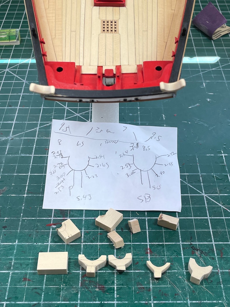
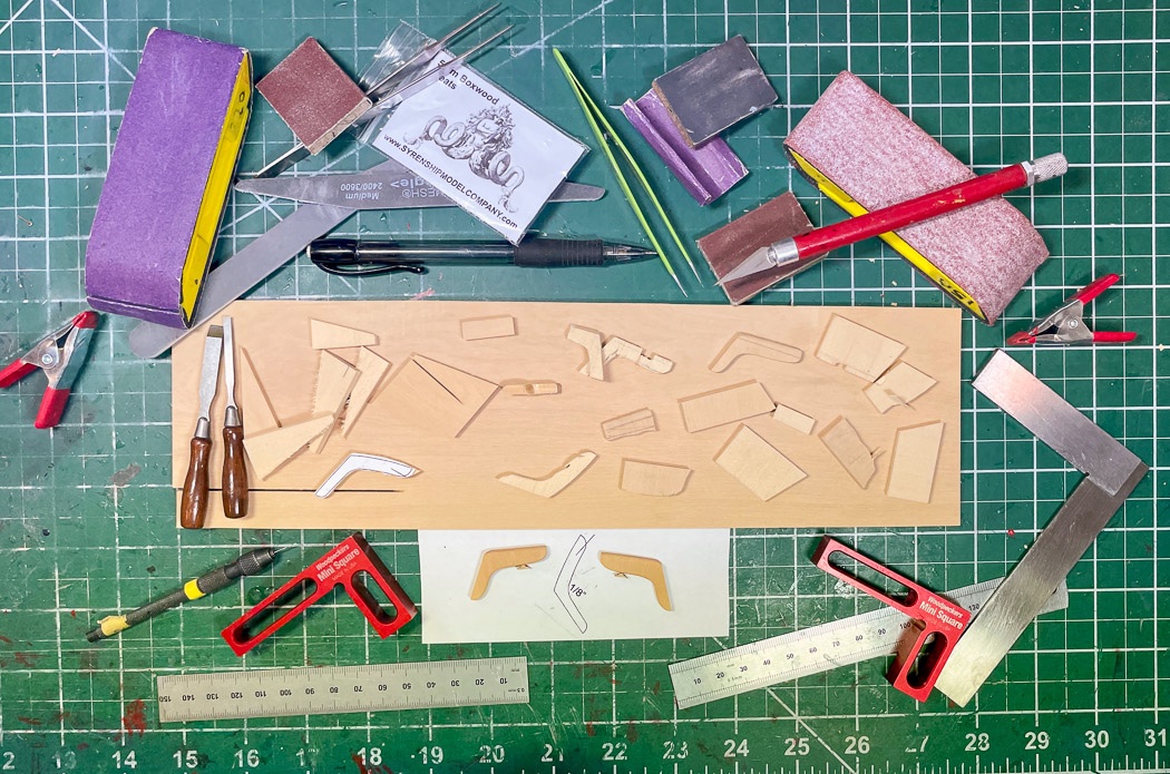
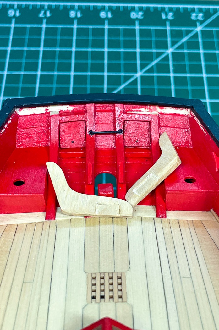
Once I sorted out a process and the scale and finally got one about 50% near what I wanted I stopped and made the second one. One of the many challenges of these things is making the second one identical to the first. My approach, rather than finish one at a time was to bring two along together. There is a lot, a lot, of sanding to get from the Y blank to the shape and size I wanted and get the angles needed. I kept the two in balance with frequent measurements at key points with digital calipers, and kept track on a series of small papers (only the final one is shown) kept next to the sanding tools. I used of different grits, blocks, sticks and holders and a needle file or two here and there. It took two days of taking my time, slowly reducing the blanks into identical crutches resulting in what the photo shows finally attached to the stern then finished it all off with wood filler along the seams of the stern rail. Did I mention there was a lot of sanding.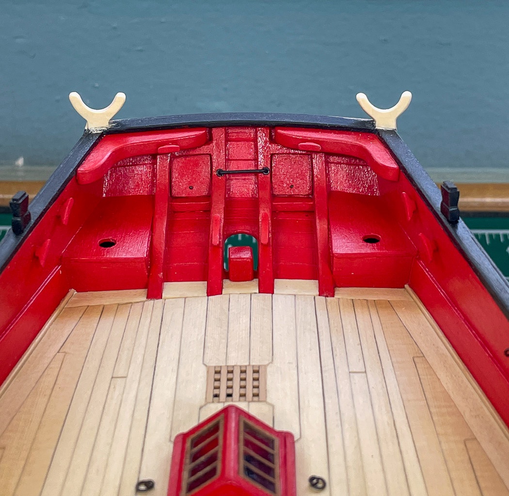
I recommend this approach. Rather than make one and copy it, make two together, reducing and shaping slowly just tenths of millimeters at a time. As I noted, I had several false starts on the first one - but once I had the basic Y blank right I had no repeats on the second crutch. I pinned and glued them on then made the final adjustments, filing the tops parallel to the water line and then turning them inward on the angle the boom, connected to the mast, would rest, Finally I lightly smoothed and rounded all the edges and it was ready to paint.
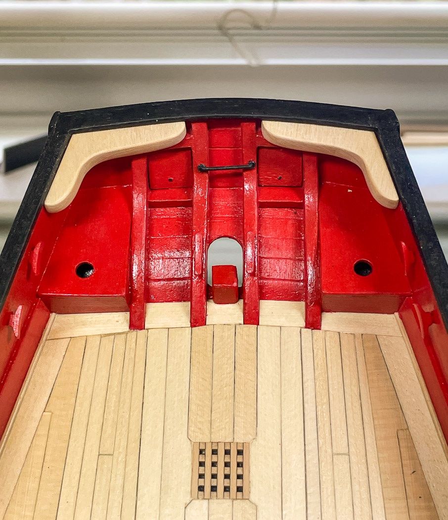
Stern Complete
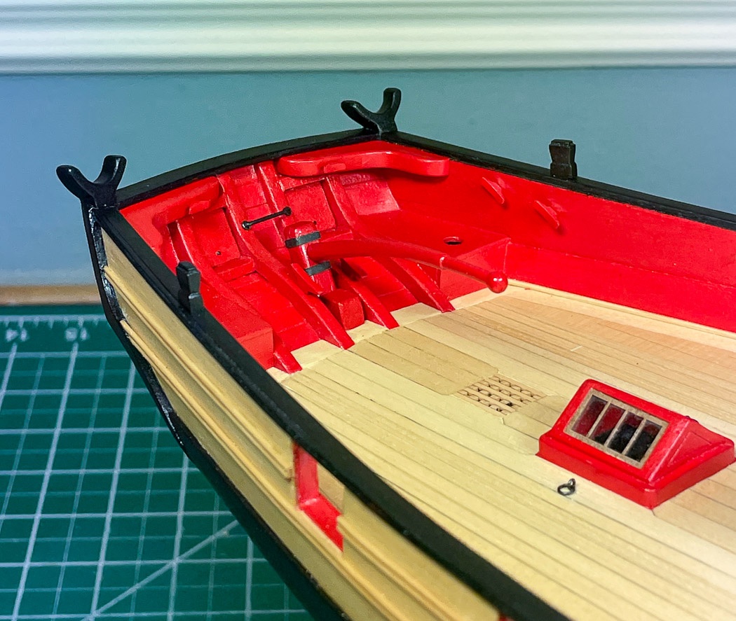
I’ve reached something of a milestone. The stern of my Cheerful is complete. I’m pretty happy with how its turned out so far. One challenge after another has been met, I’ve learned more new things than I can count and used tools I didn’t know I needed (ok, wanted). I have more challenges ahead, like how to shape and file brass strip for the stays which is up next. So I’m off to do that, but I can look back (see what I did there) and see a portion of the hull now finished.
Thanks for stopping by.- MEDDO, AnobiumPunctatum, Matt D and 14 others
-
 17
17
-
Thanks everyone for the likes and comments. I appreciate your stopping by. Working on the boom crutches now, they are fun fun.
-
53 minutes ago, bartley said:
the z one is tight as you describe.
That’s interesting, it’s my Z one that’s the issue too.
-
Nice rope work Tim - it's looking great. I like the crisp look of a well painted model, the black and red are a nice contrast to the wood and white hull. Very nice looking ship you've got there. Well done!
BTW where did you find your build board stand? I've looked for those and always seem to get an out of stock notice.
- VTHokiEE and Old Collingwood
-
2
-
I get items from Chris sent to the US via UPS in a few days. Items from a UK model shop sent via Royal Air Mail can take weeks or months. Items sent within the US from Chuck via US Post can take two days or two weeks. It makes little sense these days. I could probably purchase the books for Chris and send them to him via UPS and get them there sooner than the US - Royal Mail route - granting that might cost as much as the books. Note none of this is the fault of the senders.
- Canute, thibaultron and mtaylor
-
3
-
7 hours ago, bartley said:
always approach a setting from the same direction
Yes I always do this. I’ve had no problems getting accurate cuts. I mentioned I cut a bunch of timber heads easily within a .1mm accuracy by carefully establishing a zero start point, all of which came out identical. My comment was only in regard to stiffness of the zero set sleeves. The knobs turn just fine, the table moves smoothly and the axis settings are quite accurate. It is a small thing, I shouldn’t have mentioned it or at least described the issue more clearly.
-
It isn’t the turning knob adjusting the table, but the black collar on each of those turning easily to set the zero mark while not moving the adjustment of the table. Yes I know about that gibs adjustment (forgot they’re called gibs). The table moves smoothly.
And if you told me about gibs before yesterday odds are I don’t remember🙃. Anyway, I’ll Google it or contact Proxxon. It’s not a big deal.
-
-
Small things take time and iteration to get right. That’s the lesson I have to remember at this stage of the build.
The Tiller V.2
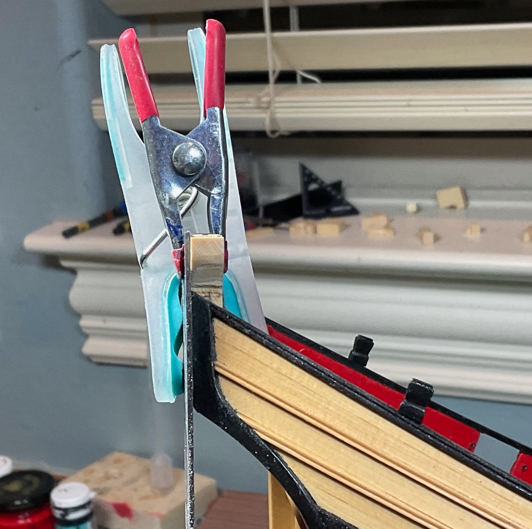
I decided to re-make the tiller. As I did the last time I started with a square length of boxwood, a couple of inches longer than the tiller, and turned it on the lathe after following the 7-10-7 rule to remove the edges with my mini-planer. I wanted a different tiller handle and did most of that on the lathe with needle files and sanding sticks.
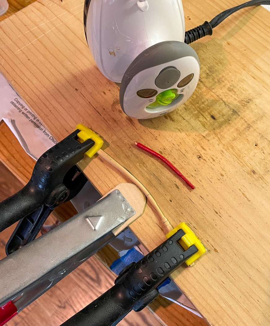
Out came the bending station. Just as it is for planking, the heat of the iron made for a relatively easy bend, though it did require a couple of iterations to more slowly work the shape than with a standard plank. By using a metal clamp in the center I was able to tilt the iron onto it so the iron didn’t physically touch the round tiller - I used steam, it worked well and took very little time to get right.
I got a better result the second time around, more of a bow instead of a bend, beefier, and a better handle so I’m glad I took the time. I checked it’s height with mini-me on the deck, it looks right to me now. And then off it came and along with the rudder up on the shelf it went until I install them later. I have a lot of stuff on the shelf now, install day is going to be fun whenever that is.
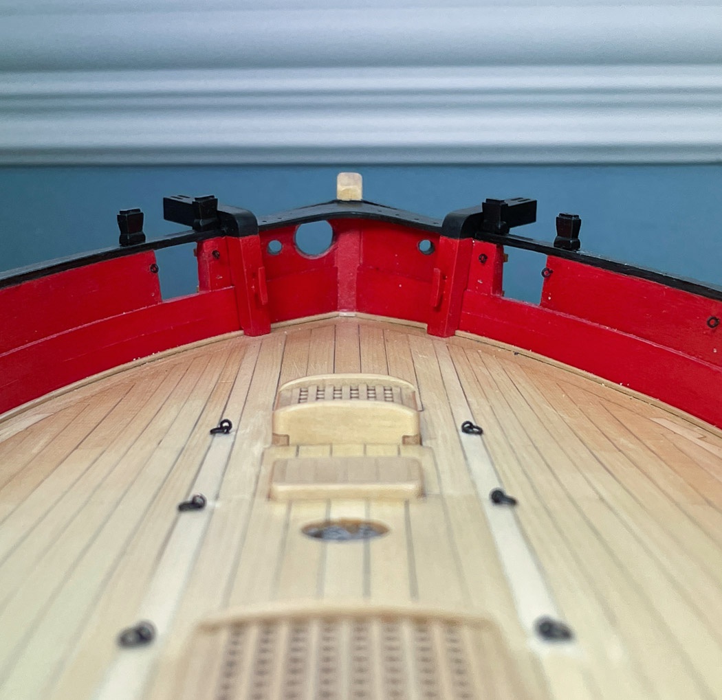
The Knees
These were not simple and serve as a reminder this is mostly a scratch build, I doubt even if they were laser cut it would have helped much. I started by duplicating the drawing from the plans with the scroll saw - it wasn’t even close and I tossed it aside. Back to card stock to determine the angles, always the angles. The first step is getting the stern and sides and to decide on the length for both. I settled on 25mm on the stern and 20mm on the bulwark for no other reason than it looked right and it was more or less in line with the plans. I used my Byrnes saw to cut the blanks from 4mm sheet.
There were a few iterations as I discovered the various angles and notching I had to account for, it wasn’t initially obvious to my untrained eye. I quickly determined the yellow cedar was a bit soft for all the shaping, sanding and beveling required (my problem not the wood’s) so I turned to my precious and limited store of boxwood. Before cutting them to their ‘knee’ shape I worked to get the proper fit snug into the corners and just below the cap rail. More angles, the transom curve and the flat cap rail required beveling both top and bottom, and then there are the stern frames, the knees are a tight fit between the rail above and the frames below.
It wasn’t pretty - I notched the bottom of the knees and had to remove a bit of the frames, seaworthiness is assured by the tight fit, or so I decided. I scraped some paint off the transom just to ensure good surfaces for the glue. I chose TiteBond for this, I needed a few minutes to get them seated with the proper angle along the bulwarks and I didn’t want to test the strength of just PVA. These knees are there to stay.
The boxwood sands nicely into shape, I gently rounded the outer edges before I glued them in. I was momentarily tempted to leave them natural - it would make no sense but they look nice.
I added the smaller cleats as shown on the plan. I’ve used three different sizes on the model so far, all from Chuck’s store. As before there is some sanding to remove the char and to shape them a bit. Like the other cleats these are pinned on using the stem of an eyelet. Having gotten past my natural look impulse, I painted it all my usual Red.
The knees were another of those things I had to stare at and think about to decide the process and order of things. It was a good move to get the fitting right before cutting them into their final ‘knee’ shaped, it gave me something to hold onto as I tweaked and tweaked and tweaked again to get the required tight fit, top, bottom. left and right. It took a good deal of time, several days, to get through the iterations for something seemingly so simple and maybe not that noticeable in context of the larger ship. I will say though it was rewarding when they were done. Something I can look at, know what went into it, and think to myself - I made those. I showed my wife, who took a look, looked at me, and said “those are nice…..” and walked out.
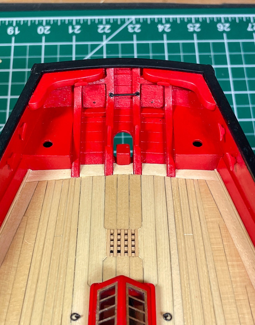
Timber heads
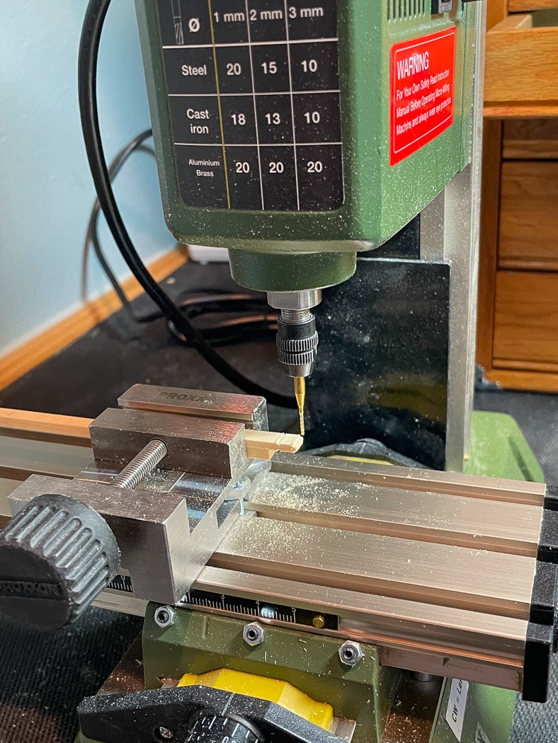
I’ve come up with my own way for making pillars and by result, timber heads. I know there are better ways in using the mill for the total job, Derek has been kind enough to share one of those. My method is a hybrid. For the timber heads I’ve cut the “cap” by cutting in .8mm from the top and .4mm deep on all four sides then dropping down 4mm and cutting a .3mm deep all using a 1mm cutter bit. I usedmy freshly sharpened chisels to slice from the top down to the cut to shape the timber head, which of course isn’t square. At this point I’m just more comfortable, and considerably faster, cutting it partially by hand with the chisels. I really like the mill, I’m learning more how to use it - but it’s a process to set an accurate zero on two, sometimes all three axis and repeating that for each side after I flip it and again for each of the 5 additional timber heads (actually 6 additional, I choose the best six after cutting seven) so that all are completely identical. While it’s true I can make .4 and .8mm cuts, that only happens with an accurate, repeatable zero starting point. The Proxxon mill is great, but I wish the zero turning dials were a little bit smoother as I set those zeros, maybe they wear in over time. Anyway.
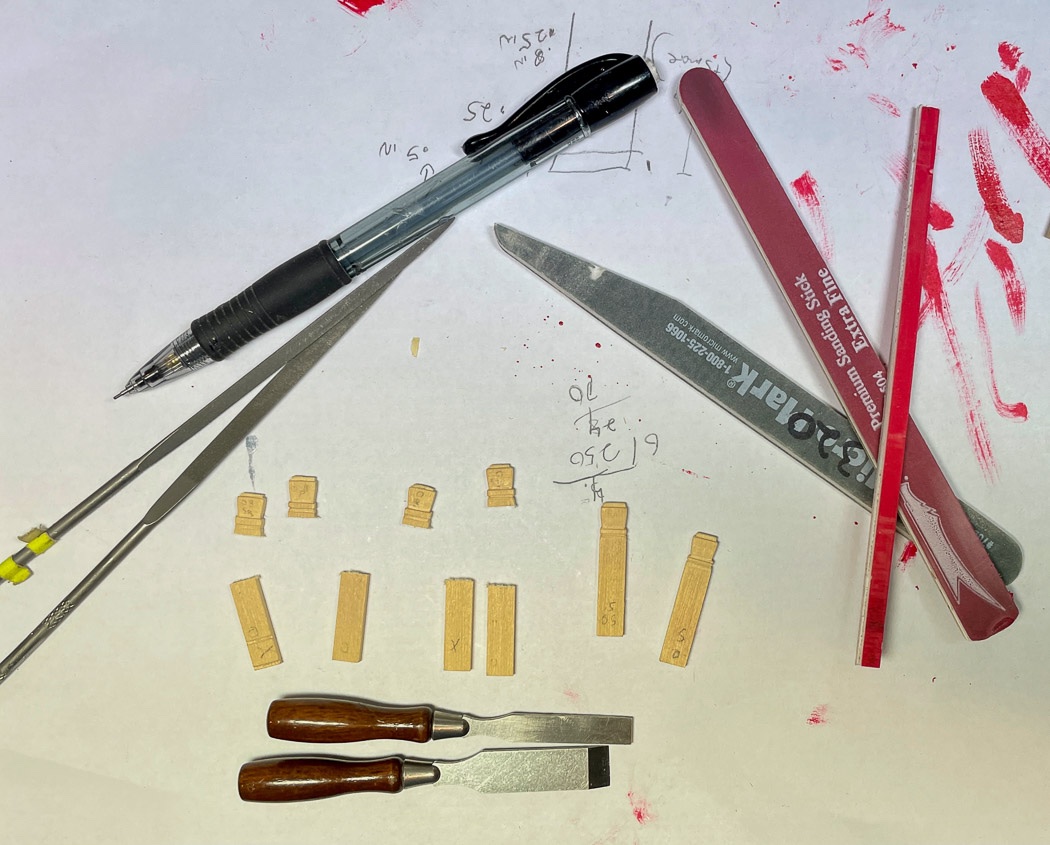
In addition to the chisels, I finish them up with files and sanding sticks. You might notice the paper below in the photo, I spend a little time, and that iteration thing again, getting to the sizes and cuts I think look right. There is no clear design and the size is a bit flexible. I once again got to exercise my - if ‘it’s not right rip it off and do it again’ motto. After making all six timber heads I decided they were too wide and tall so I tossed them and started over. I guess I could have figured that out after making one - but I didn’t until I saw them sitting (not glued fortunately) on the cap rail. I drilled holes and pinned them all into place using those ubiquitous little nails from past models with the heads removed.
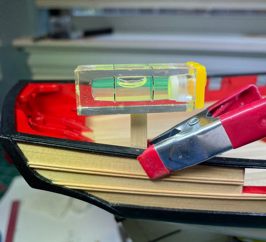
The four on the bow were straightforward, once I got the size right, the two on the stern are a little tricky - they need to be perpendicular to the water line, while mounted on a cap rail that has a significant sloop at the stern. I leveled the boat in the Amati working stand then used another level (these little ones come in handy over and over) and some scrap wood to determine the angle, cut the scrap on that line as a template and transferred it to the timber head.. I had made all the timber heads intentionally long to give me grip when cutting and filing and plenty to work with to cut the angle. BTW, that’s light glare, not bad painting on the wales and fashion piece, along with a little dust which will all get cleaned up later. …close up photos reveal all …
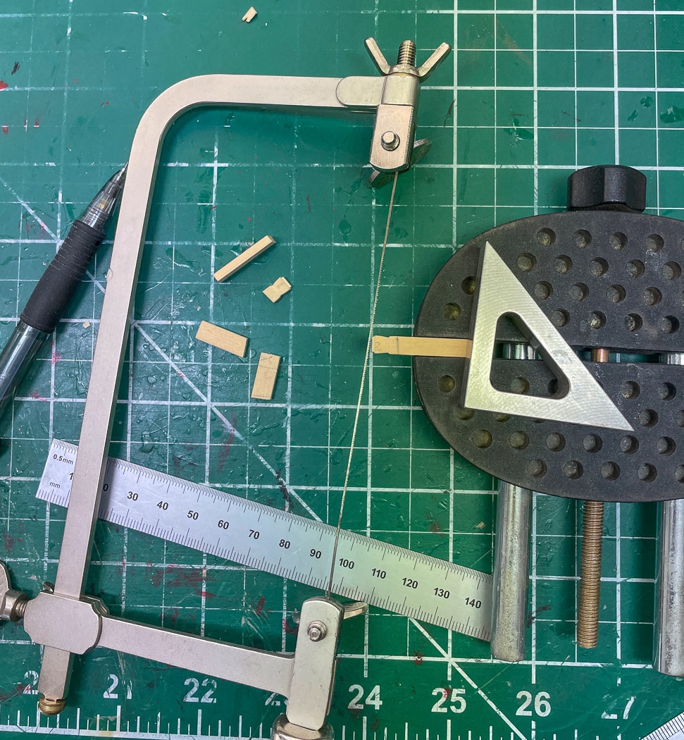
I have “The Cutter” I normally use to chop small pieces on exact angles, but in this case it would not get as flush a cut as I needed on the thicker wood. I got this jeweler’s saw to cut the stern frames way back when, it’s coming in handy again now. In addition to this cut on the stern timber head I used it to cut the knee part of the knees (much too small for the scroll saw, at least for me) after I had fitted the pieces as described above. It makes short work of cutting wood too thick for my #11 blade and is accurate in staying on the cut line.
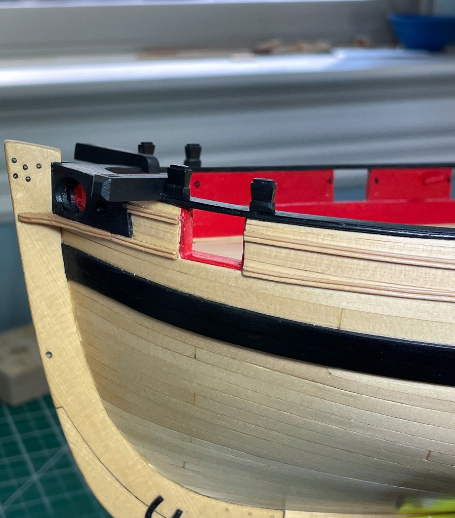
Here they are all glued on and painted with Admiralty Dull Black, its all good and on to the next thing. I’m betting this is more than you ever wanted to know about timber heads. Everything is more interesting to me when I made it from scratch I guess.
Speaking of which, time to move to the next fun item, the boom crutches - and guess what - there are a lot of angles involved. Thanks for stopping by, the likes and especially the comments are always appreciated.
-
I just ordered Vol 2 of the Rogers Collection, let's see how long it takes to get to me.
- mtaylor, Canute and thibaultron
-
3
-
6 hours ago, DelF said:
So have I -
Wow, so this is why you had to let the butler go, paying all that crew must weigh heavily on the estate. My captain works on half salary due to current economy.
- EricWilliamMarshall and DelF
-
 2
2
-
7 hours ago, DelF said:
whether or not to paint the hull.
I think you should copper it😁🤣
Although it’s pretty boxwood it’s more how it looks as a ship accessory on display so in my opinion I’d paint it, at least below the waterline.
I’m sure it will look great either way. Congrats on the ratlines. I have an actual boat at our Lakehouse. I’m pretty good at full scale clove hitches at that scale. It’s the tedium of one after another that gets to me, and the forced labor of Just..,Do...One...More...😩
-
-
Good plan. Someone can start a Brexit thread separately
- chris watton, hollowneck and Canute
-
3
-
Nice to see another Cheerful underway. It’s a great model, I’m sure you’ll enjoy it.
- AnobiumPunctatum and mtaylor
-
2
-
The pins on the spars are fine and a good idea Tim, of course it isn’t historically accurate, but it’s a model. You don’t want them bouncing all over the place, Cut the pin shorter and/or hold it tight against the mast with a pin dab of C A.
-
Yes the spike turned out to be very helpful, it’s not something I’d done before because the Nelson frame was pretty wobbly for the mast. Side supports, that leave room to adjust as you described, are likely a good idea. I used wood glue, Titebond (not white PVA), dripped down that frame slot on both sides. It is tricky with this model, a hold your breath moment aligning it.
While you’re here think about how you’re going to display it. If on pedestals drill the holes now and supports there. The holes need to go past the keel into the, rather fragile, MDF frame.
-
I’m sure you’re watching the reference lines with your reinforcements, remember those lines are the top of the wood you’ll place there for the gun ports, you need from below them too. It may not seem like it now but getting the bottom of the gun ports right is important later when you’re doing a 1/64th rabbit.
I’m enjoying seeing another Cheerful come to life.
- Edwardkenway, JpR62 and Saburo
-
3
-
Real ships also had good seat to hold them, this model doesn’t. It’s a bit ambitious to try to center and hold it with rigging. More than I’d try. The odds are if you have a mishap it’s going to be a droopy or off center mast. I’d glue, again I described how I did it in the log.
Just my opinion, up to you.
-
It’s going to be interesting to see how you work this out and keep the hull integrity. I will enjoy watching you progress but don’t have any help to offer other than I can only see about 1 square inch thru the skylight. Should be fun, enjoy.
Do keep in mind the stern frames are a delicate part of the frame in your planning.
-
-
Thank you for the likes and those taking the time to comment. It is all greatly appreciated, especially those whose work I have long admired and followed.
The heads, or rather the afts are and will remain an interesting feature of Cheerful, wind direction or proximity to the helmsman notwithstanding.
On 1/20/2021 at 3:11 AM, DelF said:Also, I couldn't see any drainage holes in the stern - I hope the seats of ease don't drain into the captain's quarters?
Thanks Derek. I know BE added such drainage holes, I decided mine would be less visible (as in invisible) there is only so far I'll go in honoring those who serve and poop. 😄
On 1/20/2021 at 2:47 AM, Blue Ensign said:I too had thoughts about the positioning of the seats of ease,
Thanks BE Your logic on the topic is one I followed, I need more clever terminology as you provided the best I could come up with was "Well, s**t might as well." Hardly does it justice I know. 😄 Not to mention I continue to consult your log as a frequent reference on the big steps, you may recognize many things I do, as they are ones I learned from you.
On 1/20/2021 at 1:54 AM, JpR62 said:this log is so detailed and informative!
Thank you, sometimes I think I get carried away with the details and bore the socks off people, I just can't help myself though.
On 1/19/2021 at 8:21 PM, Rustyj said:doing a great job
Thanks Rusty, high praise from a master builder - your current work on the Duchess and Winnie are amazing. And of course I borrow many good ideas from those logs.
On 1/20/2021 at 8:43 AM, Chuck said:nice work.
Thanks Chuck, coming from the master and designer that means a lot. You gave us a great model, I continue to enjoy the building of her.
On 1/19/2021 at 7:58 PM, Moab said:continued great photos and descriptions
Thank you, I glad they are helpful and appreciated.
On 1/20/2021 at 8:33 AM, bartley said:other comments are true though
Regardless of wind direction the image of the helmsman with seated individuals either side remains comic to me. 😄
- bruce d, JpR62, Edwardkenway and 4 others
-
7
-
Such neat and crisp work, great job.
- FrankWouts, chris watton and Rustyj
-
3
Securing the Cannons
in Discussion for a Ship's Deck Furniture, Guns, boats and other Fittings
Posted
It isn't an age thing, all of us are challenged by that. A quad hands is essential to working with blocks and rigging, do you have one? Here's the one I have from Amazon, its a US link but I know Amazon in the UK also has them Quad Hands
By the way, I'd definitely paint the cannons, the cast metal would seem unfinished to me, something you might regret later. Most cannon of the era have red trucks with black metal. If you choose not to do the weathering definitely use a paint that finishes as simulated metal, not something glossy. I use Admiralty Flat Ironwork Black and Admiralty Red Ochre for the trucks you can get both here, and its local to the UK. Admiralty Paints.
There is a lot of things to learn and experiment with for your first model. I'd suggest not overthinking it and learn the basics on this one. I'm on my 10th and still learning something new on this forum every day. Enjoy the process.