


DelF
-
Posts
1,398 -
Joined
-
Last visited
Content Type
Profiles
Forums
Gallery
Events
Posts posted by DelF
-
-
Good job on the copper. I've fallen further behind you as I've been concentrating on finishing my pinnace. Now that's done I want to get on with Speedy. I'll follow your lead and use a wood strip to define the upper edge of the copper, but as I've never done coppering before I'm not sure how smooth I need to get the second planking below the waterline. Is the copper relatively forgiving, or do you need to smooth out even the tiniest lumps and bumps?
Derek
-
-
-
Much appreciated Chuck. Thank you for designing such a cracking model. You really do excel at these smaller boats (and the big stuff as well, of course 😀!).
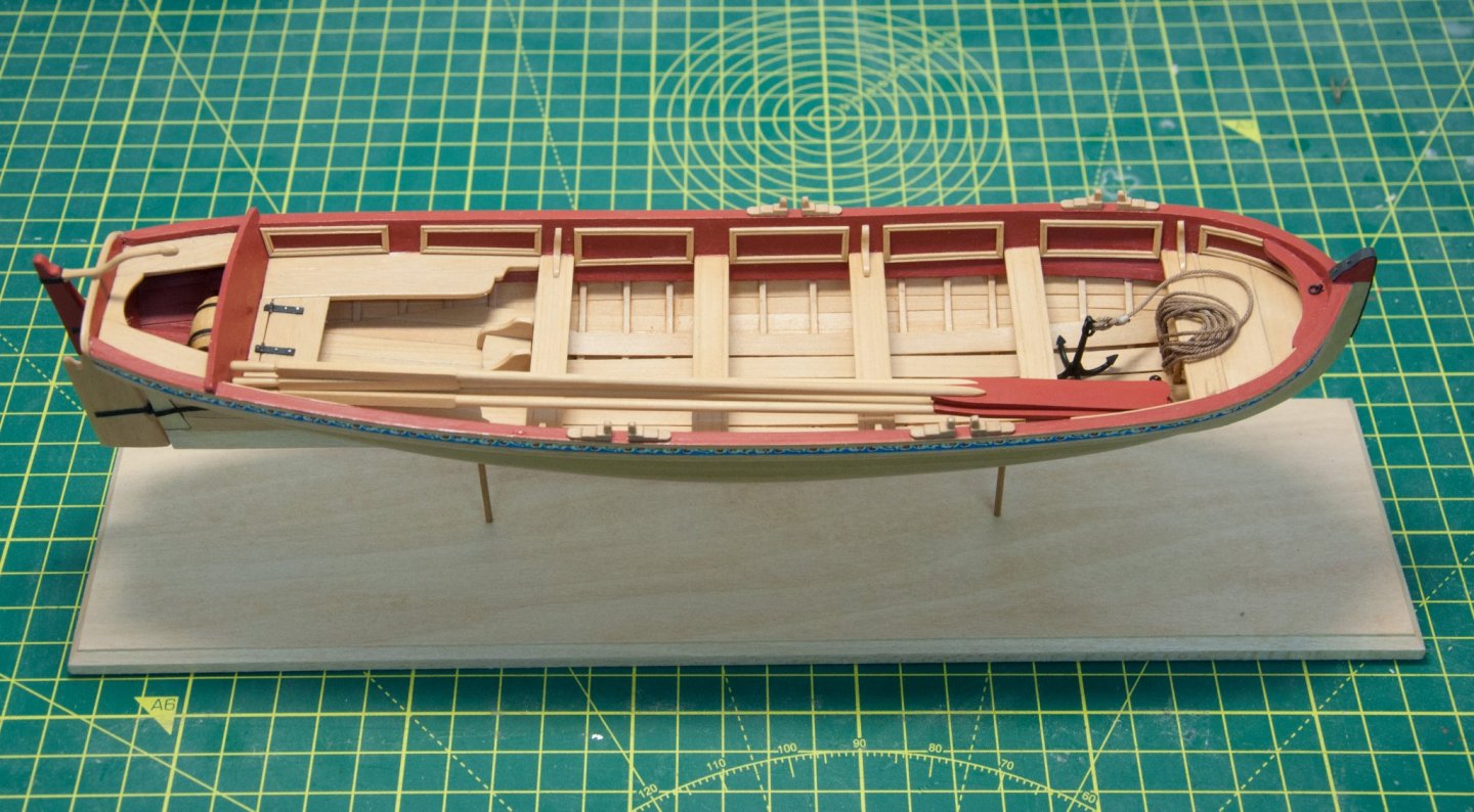
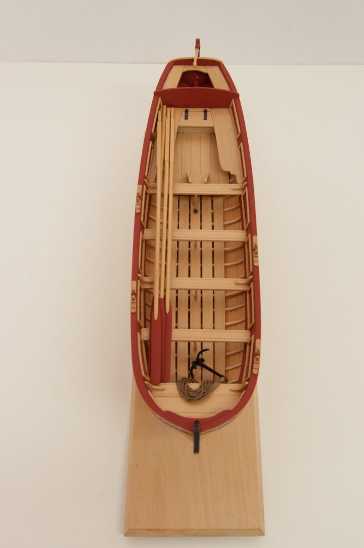
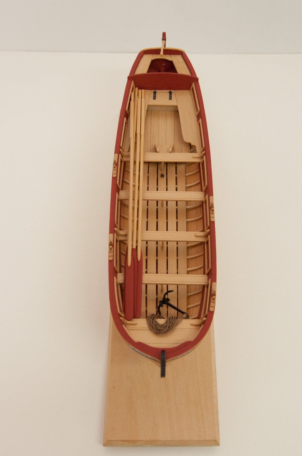
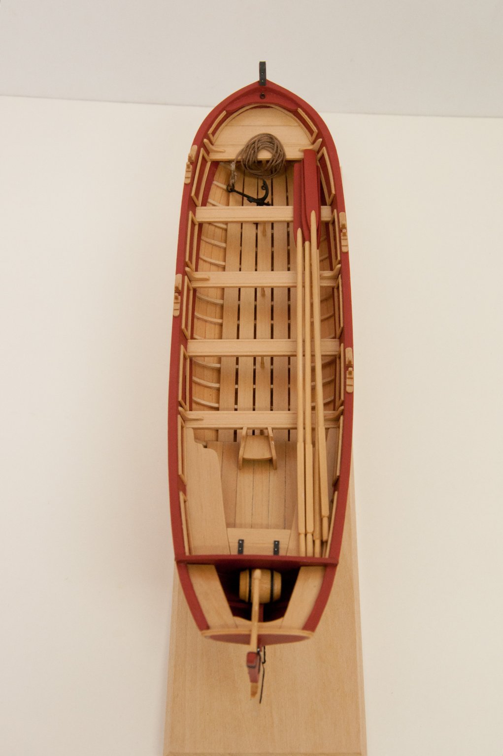
Just a couple more little jobs to finish off. The anchor was provided in the kit but the soft metal casting required a lot of fettling to make it presentable - not just flashing from the mould but the shaft was quite badly pitted. Fortunately there was enough meat in it to remove the pits and leave a decent result. I added a ring which I think would have been standard, and used some spare rope I made for Royal Caroline on my rope rocket. For authenticity I used a fisherman's bend with two half hitches and the end seized. All knots I'd done before but it's surprising how quickly I forget the techniques. As usual I fell back on the Ashley Book of Knots to remind me of the delights of riding turns and frapping.
I had a barrel left over from my recent Victory cross-section so that was stowed down near the tiller, no doubt on it's way to top up the officers' supplies.
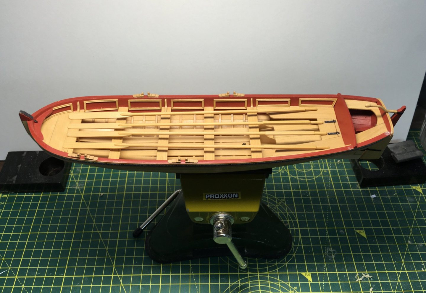
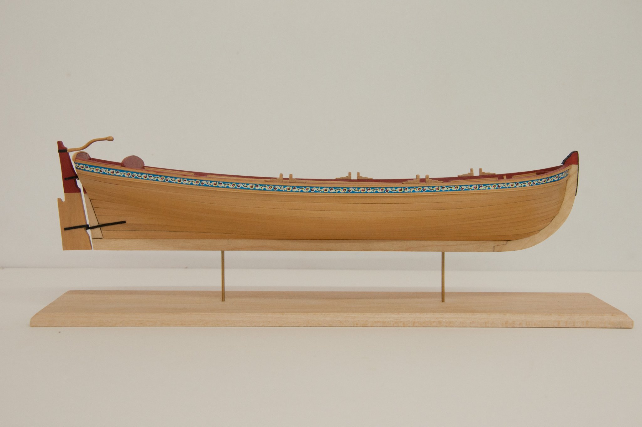
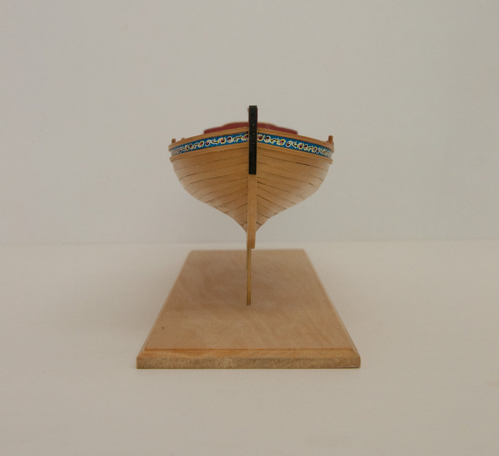
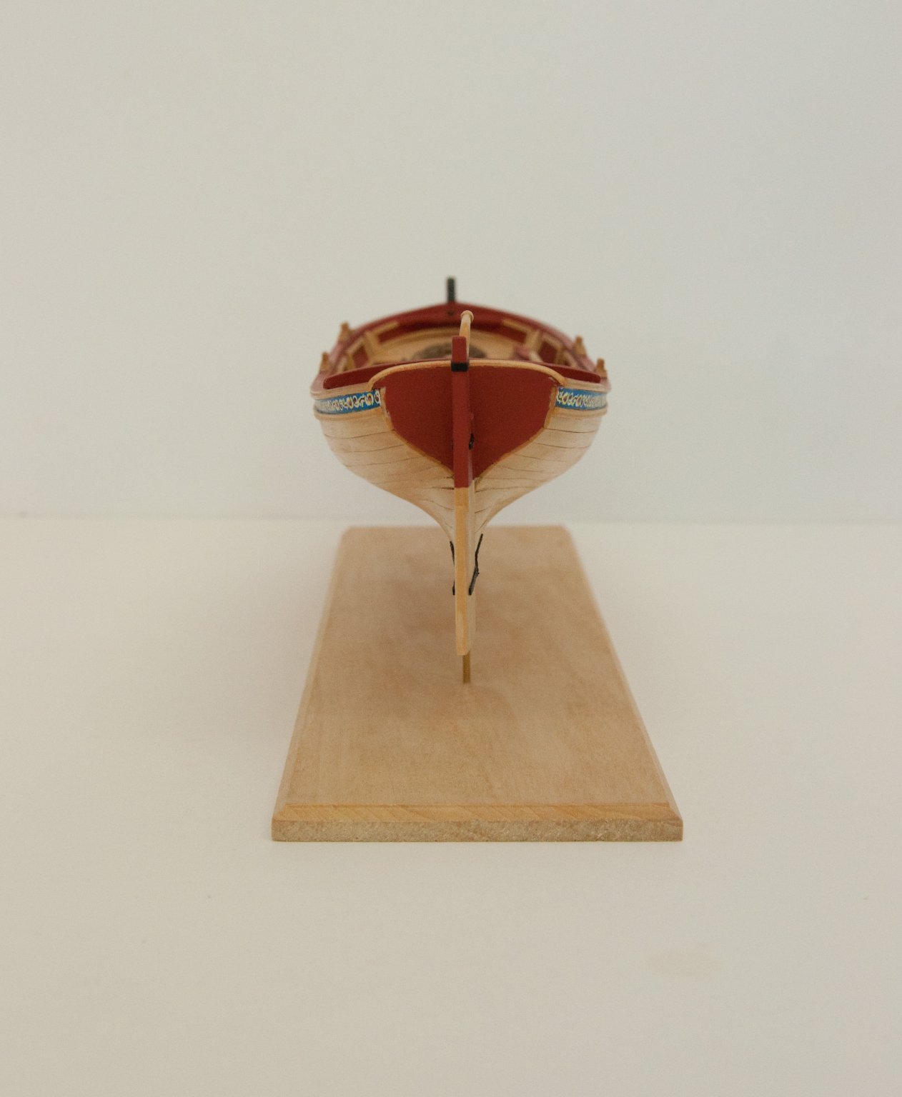
I had previously drilled the keel for 1/16" brass tube supports, but I'm not sure what to do for the base. As an interim measure I've taken the kit base and shaped the edge with my Proxxon router table (a tool I ought to use more). Here's the result:
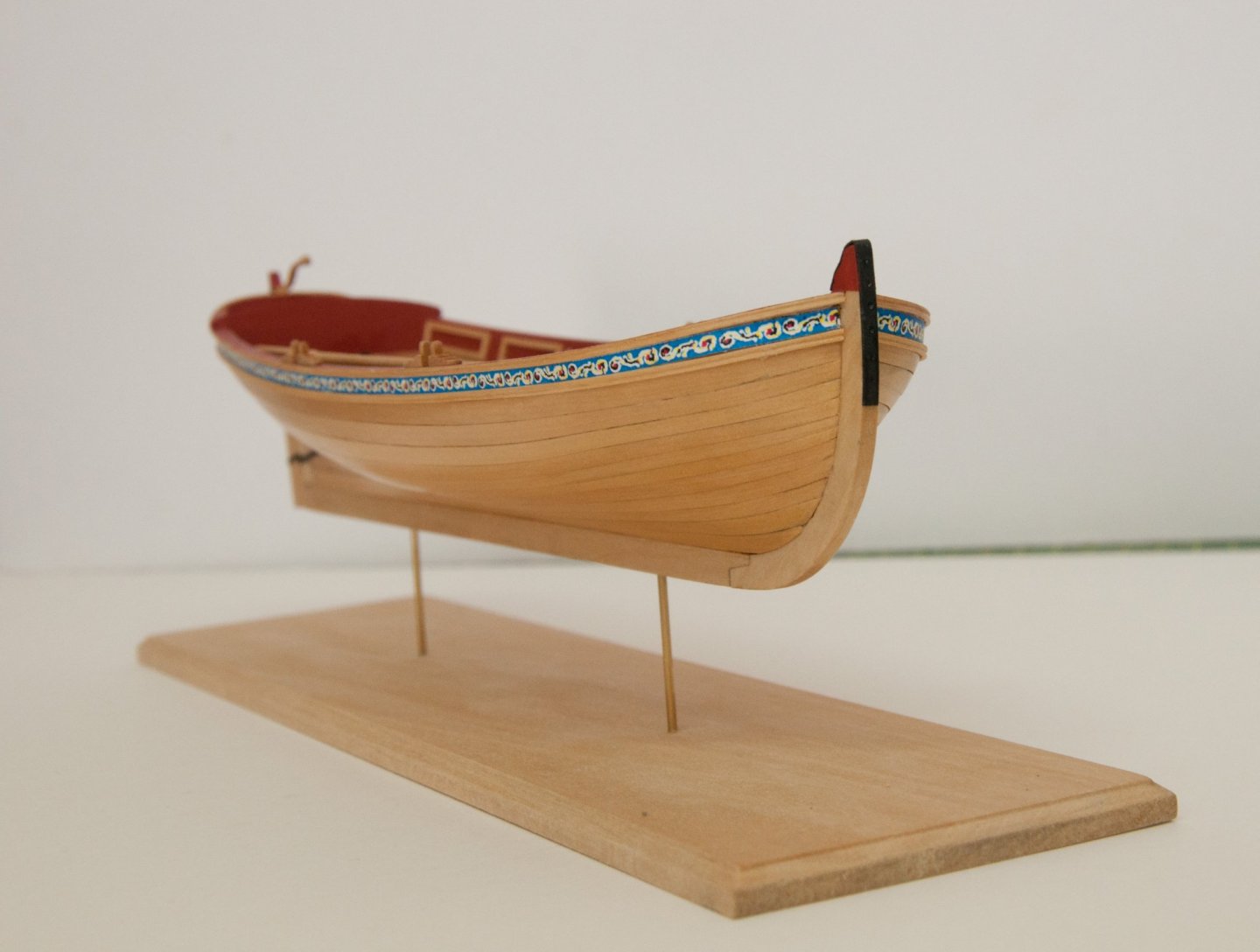
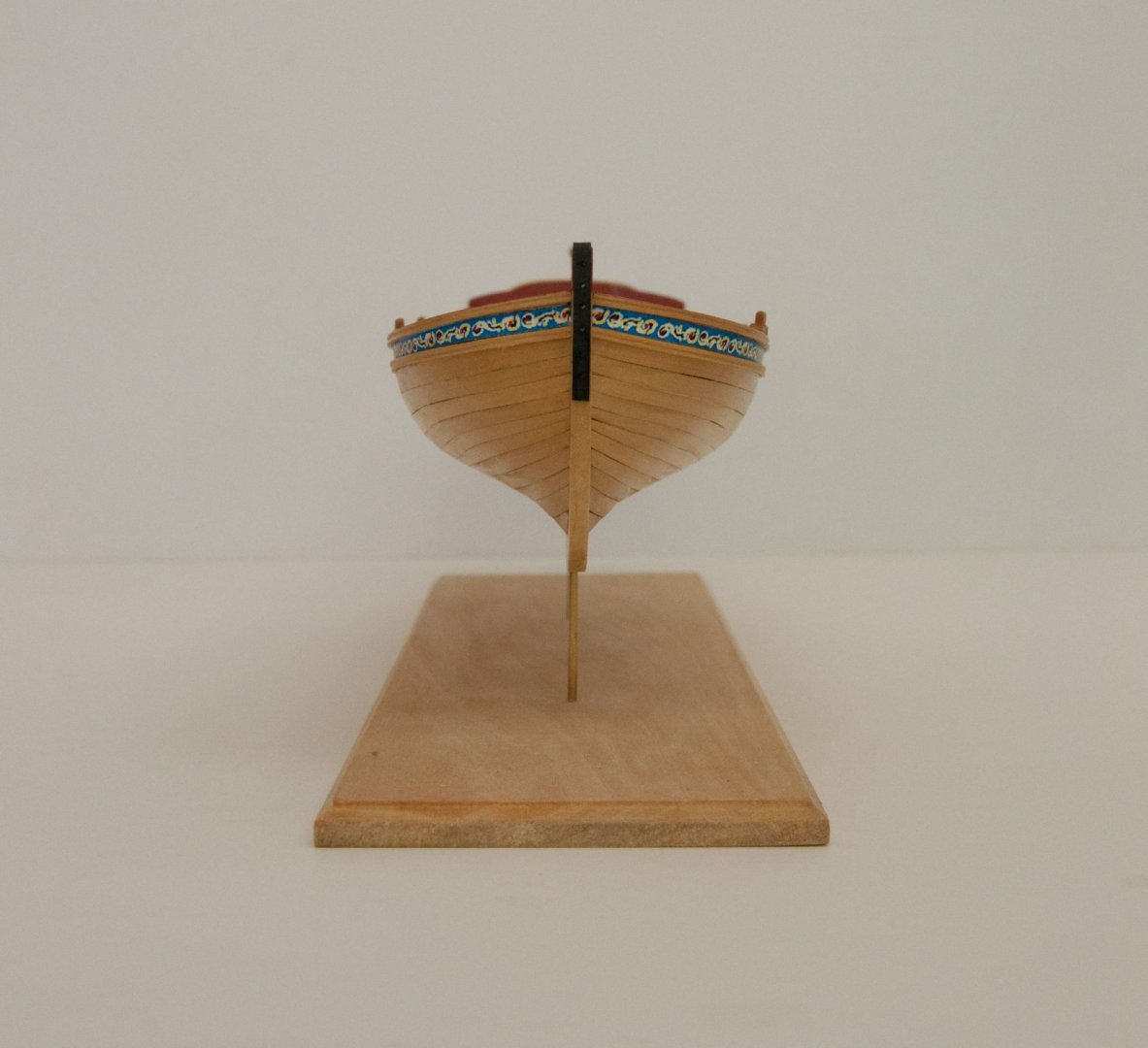
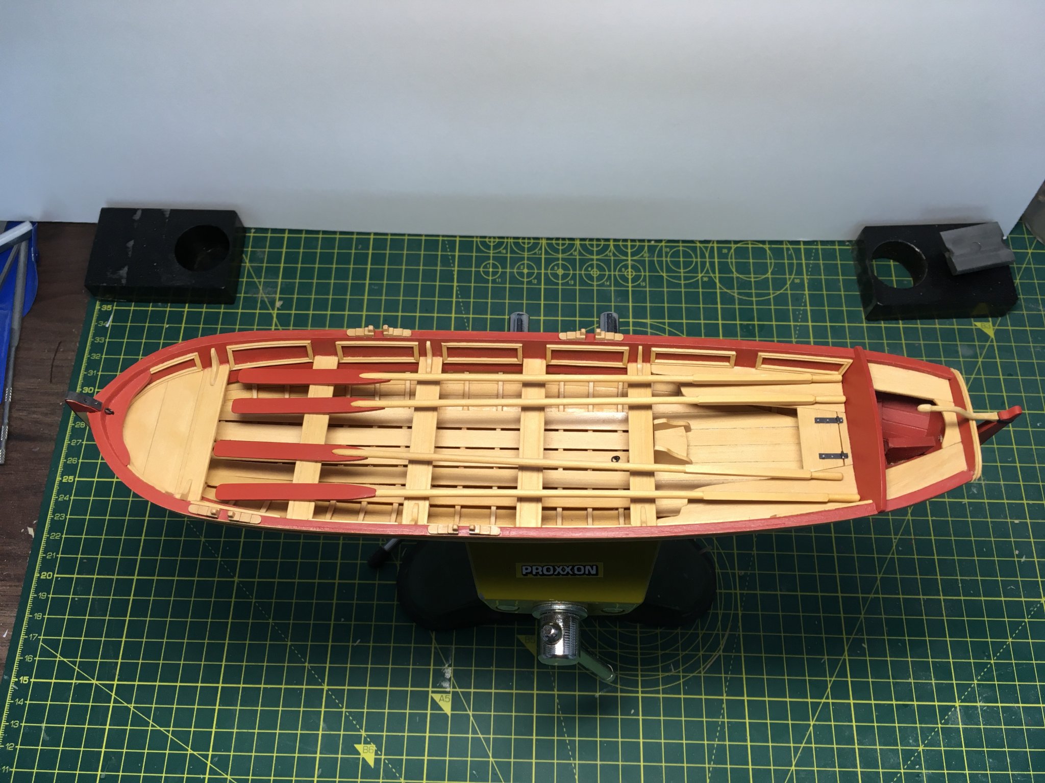
And a few more views...
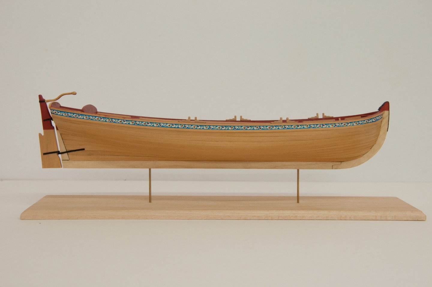

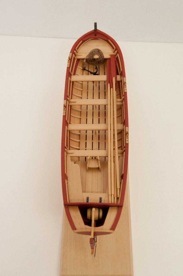
As I've mentioned before, I only got this kit so I could scale it down to 1:48 for the Royal Caroline, and I started it for no better reason than it was there on my shelf. It turned out to be a most enjoyable build, taking just over four months which is Usain Bolt territory for me. I'm pleased with the result, and I may well be tempted to try more of the smaller vessels Chuck has designed. I particularly enjoyed the fact that I could work on the pinnace alongside HMS Speedy, with each providing a break from the other. I also enjoyed and appreciated the very good pinnace logs already on the forum, and the kind words and advice from several of the top builders.
I'll ponder the base and whether or not I want a case, but for now I'll call this finished. I would highly recommend this kit to anyone looking for a relatively quick project with pleasing results. So long as you're prepared to have a go at single planking!
Derek
24 March 2020
- bruce d, Tigersteve, MEDDO and 8 others
-
 11
11
-
-
Looking really good. I agree about the sanding. I think I used to be afraid to sand too much because 1mm planking doesn't seem very thick, but it's surprising how much you can sand it without doing any harm. On Speedy I really attacked the first and second planking with coarse then medium sandpaper to smooth out the surface as much as possible and it looks like you've done the same.
Derek
-
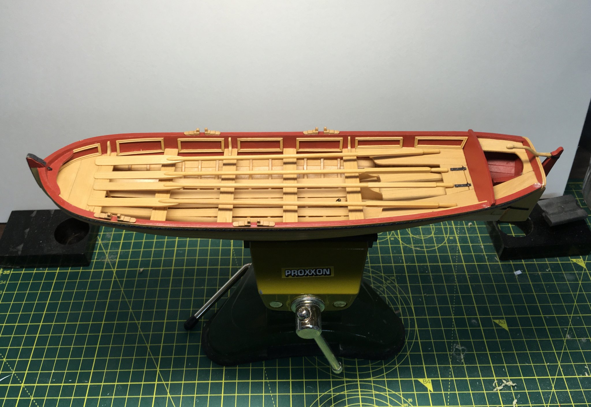
Thanks guys - I agree:
I think I'll keep the thwarts and other seats bare though.
Derek
- GrandpaPhil, bruce d, Sea Hoss and 5 others
-
8
-
Many thanks Bob for a great recommendation.
Ordered 12 March through your ebay link, delivered to the UK today (21st) very well packaged and no import duty to pay! Excellent service, particularly in the current situation. I'm looking forward to staying in and reading it - nothing else to do now all the pubs are shut 😟.
Derek
-
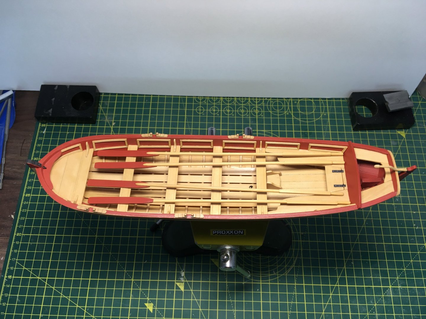
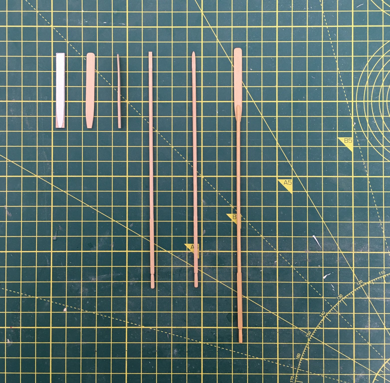
Finished the oars today. Not much else to do as all pubs, cafes, restaurants etc are being obliged to close from tonight.
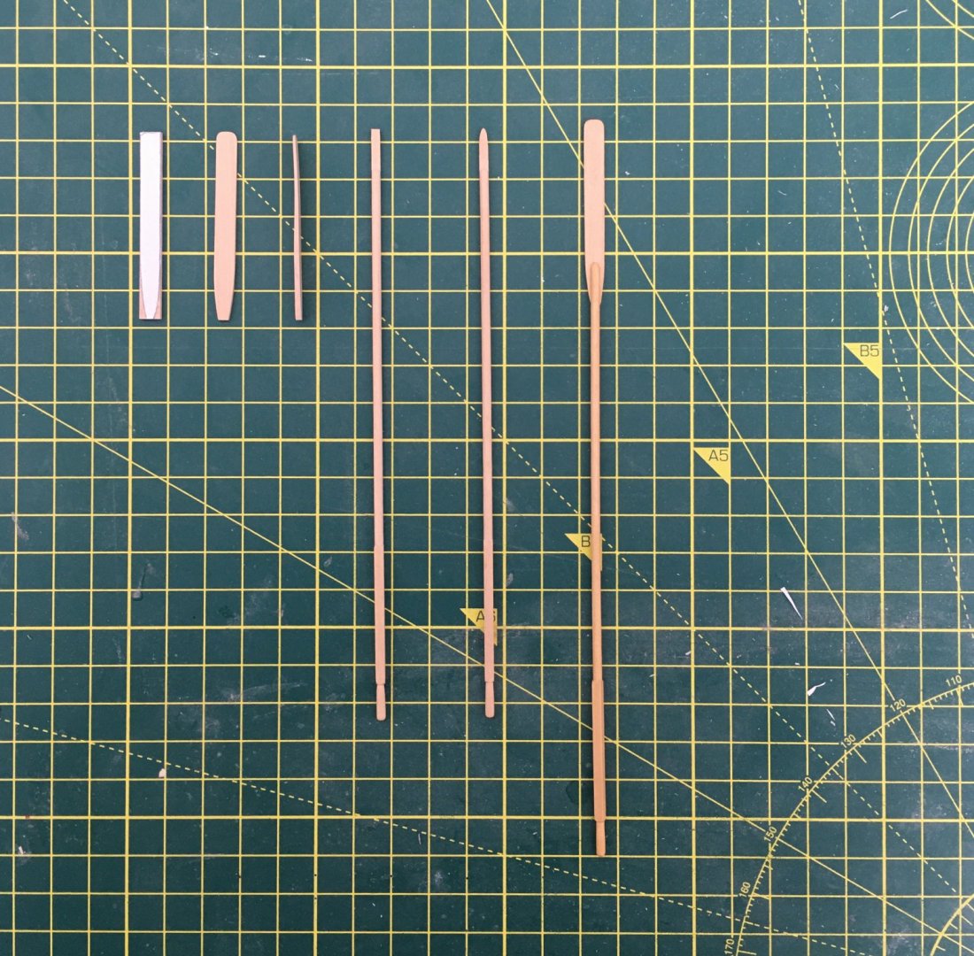
Here's the steps I took in making the blades and attaching them to the shafts:
 :
:
From the left:
- sticking a photocopy of the blade (from the plan) on a strip of boxwood
- filing the blade to shape
- thinning the blade towards the tip - I also slightly bent the blade with a plank bender
- filing a flat onto the end of the shaft
- shaping the shaft end
- gluing the two parts together
Here's the final result:
I haven't decided yet whether or not I'm going to paint the blades red as suggested by the kit instructions. I'm always reluctant to cover up boxwood.
Feels like the home straight now.
Derek
- shipman, GrandpaPhil, Tigersteve and 4 others
-
7
-
Many thanks for the likes. I hope everyone is well in these difficult times.
I've been thinking about the oars. In his instructions Chuck suggests employing a Dremel or similar rotary tool as a 'poor man's lathe', using files and sandpaper to turn the handle and the round part of the shaft. I used my slightly less poor man's Proxxon lathe for my 1:48 scale scratch built version but doubted my ability to produce anything that would pass muster at the larger scale. Funnily enough I have no problems turning spars, but I think that's because they are tapered and I probably get away with results that don't match the 'proper' taper exactly, whereas an oar that is meant to be perfectly cylindrical along its whole length will show up any unevenness.
Anyway, I decided to try a drawplate instead. I think its worth describing this method in some detail. I'm sure it's not original, and many forum members won't need to be told how to use a drawplate, but until fairly recently I was a novice at this and hopefully my description will help others new to the technique. Perhaps some more experienced people will also find this way of using a drawplate useful.
Some time ago I wanted to buy Jim Byrne's drawplate until I saw that shipping and import duty would triple the cost, so I decided to make my own. I was surprised how easy this was. If you've got a piece of scrap steel and the necessary drill bits it will cost nothing. I made mine from a small square of 2mm steel off an old machine, but a steel ruler would work equally well. The DIY approach gives you total flexibility as you can just drill the holes you need for the job in hand. Using the drawplate I was able to produce treenails and to trim down commercial belaying pins to acceptable dimensions.
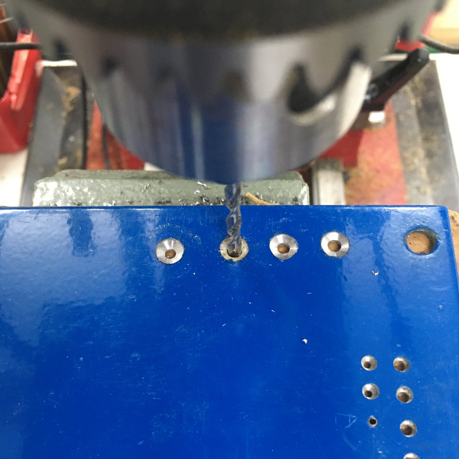
For this job I started with a 6mm/1/4" hole drilled almost through the sheet...
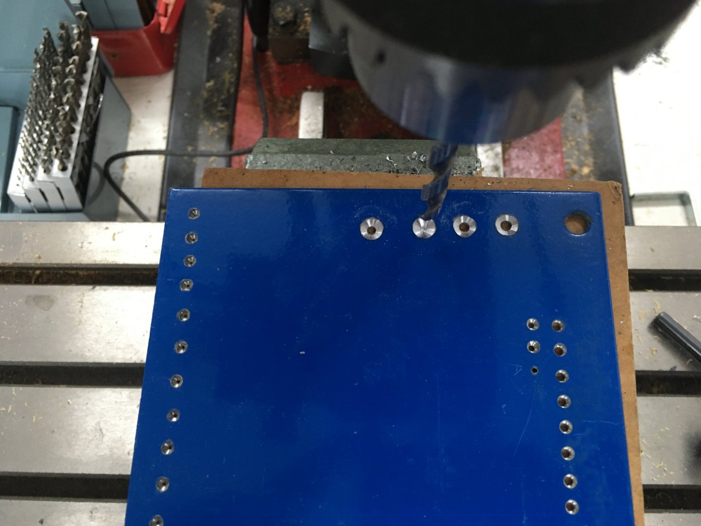
...followed by a hole of the required size all the way through:

When starting a new job you obviously need to decide what size stock you need to start with and what holes you need in the drawplate and how many. I start by looking at the final diameter I want to arrive at, and then get square stock whose sides are the same as that diameter or very slightly more - you don't want to remove more material than you need to. In effect, the drawplate will knock the corners off your square stock so it ends up round:
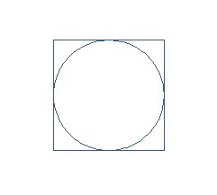
However you won't be able to knock all this wood off in one go. In fact, as you get closer and closer to the final diameter, the drawplate is having to cut through wider and wider corners, making it progressively harder to get the wood through. In my case, the round part of the oars needed to be 2.4 mm - about 3/32". So if you start with 2.4 mm square stock Pythagoras tells you that the starting diagonal dimension of the wood is about 3.4mm - this will be the largest diameter hole the wood could pass through without cutting. With a little trial and effort I found the smallest hole the stock would pass through easily was 3.0 mm. Thereafter each pass needs to take off more wood, so to make them manageable I decreased the steps between successive holes. I ended up using four:
3.0 mm - removing 0.4 mm
2.7 mm - " 0.3 mm
2.5 mm - " 0.2 mm
2.4 mm - " 0.1 mm
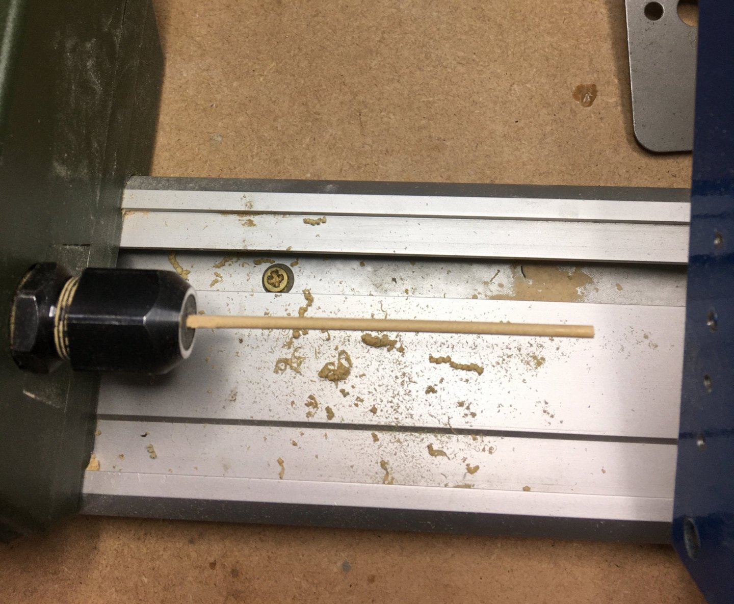
Most times a drawplate is used by pulling the wood through the plate, often with pliers to get sufficient grip. I've used this method successfully for treenails but it doesn't work for me at these larger diameters. Also the draw method works best if you are pulling the whole length of stock through the plate. It is harder if you have to work to a line as with these oars, where the round shaft connects to a square section which becomes a round handle. That's why I prefer the lathe for this sort of job, where I push the drawplate against the spinning stock, as I shall describe.
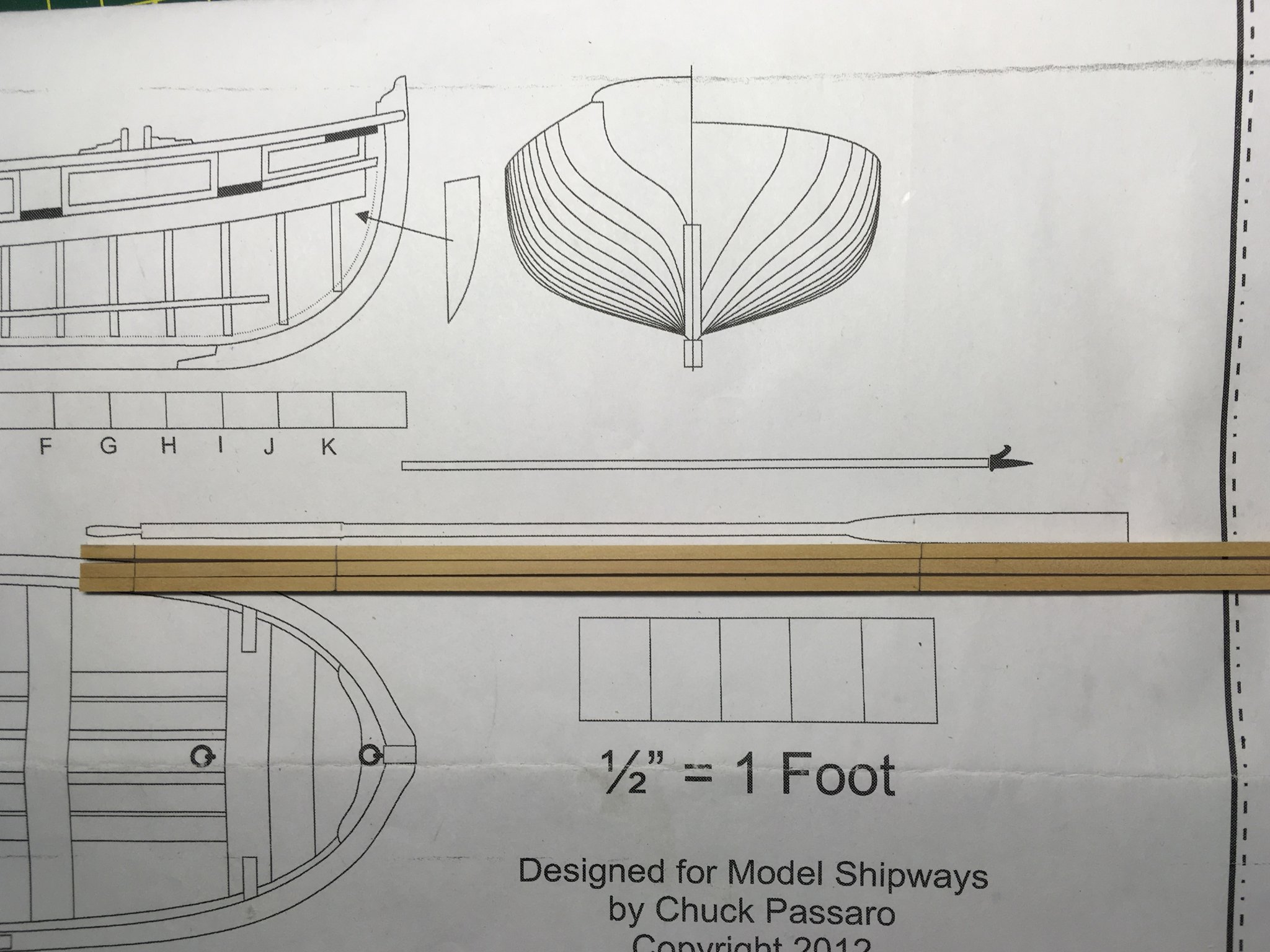
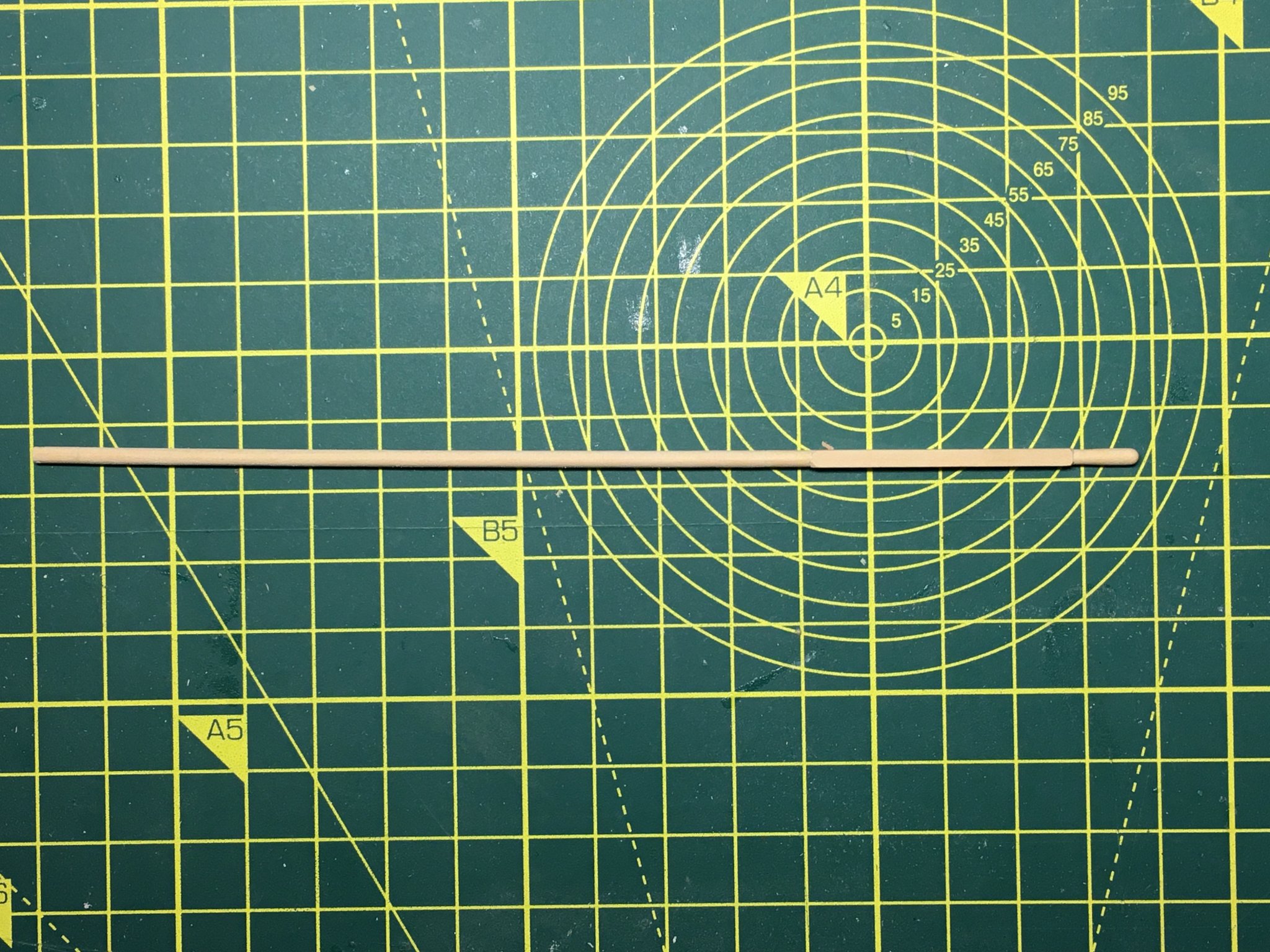
I started by cutting 2.4 mm square stock from a castello boxwood sheet, and marked off the critical dimensions from the plan:
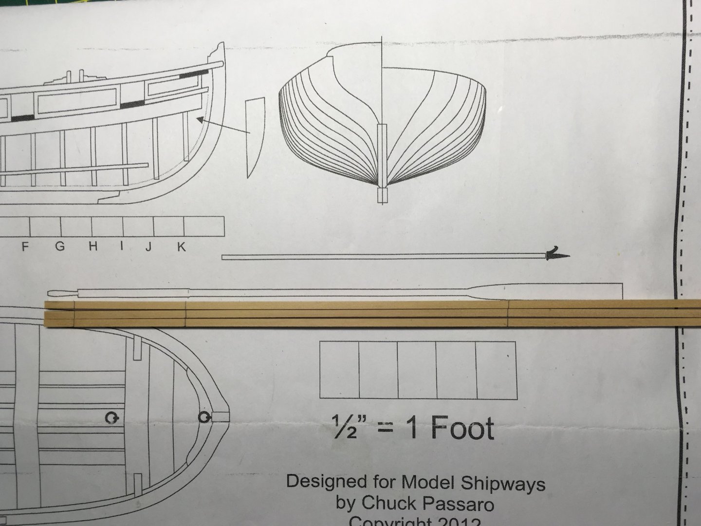
As you can see, I left plenty of spare to give the lathe something to grip. I used my Proxxon wood lathe, which has the advantage of a hollow headstock to accommodate long work. Although I have a proper metal chuck for the lathe, I found the basic plastic collets more than adequate for this task. Here, I've set up the oar blank to prepare the handle. I've made sure the collet clamps on the part of the oar that will end up round, so marks on it at this stage will be removed. The section between the pencil marks will remain square and needs to be protected:
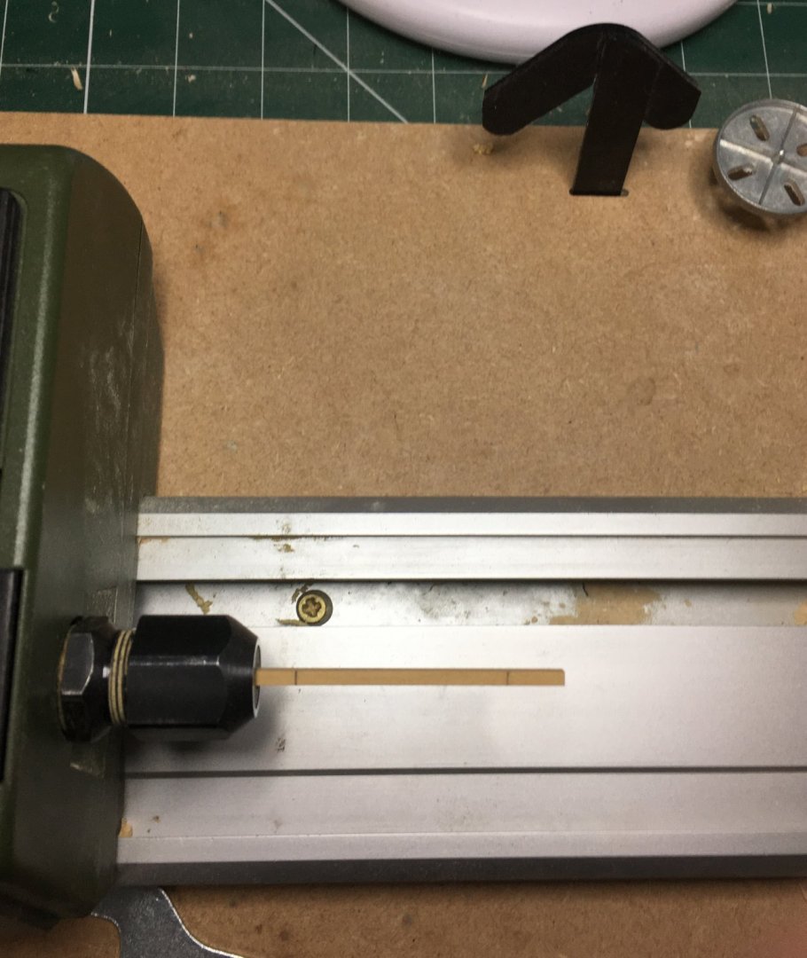
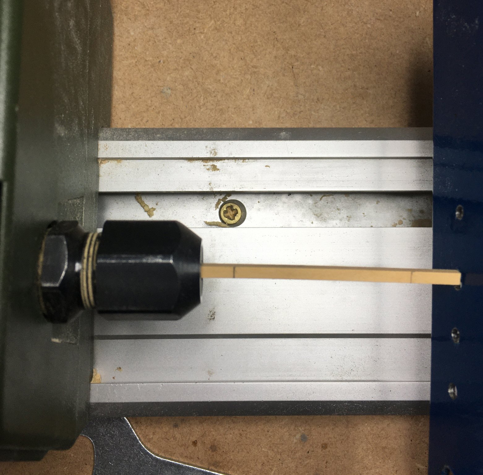
I've tipped the drawplate slightly in the next photo to make it visible. In practice you keep it vertical to the lathe bed and square to the work. Note also that the work enters from the flat face of the hole, not the countersunk side. In drilling the holes you've created a cutting edge on the flat face of the steel. I've tried it the other way and it does work, but I find it harder to achieve a good finish. Of course the downside of starting without a countersink is that it is harder to get the drawplate started on the work. Normal practice for jobs like treenail making is to sharpen one end of the stock so you can get it started through the hole. I didn't want to do that here, but I found that pushing the plate gently against the end of the spinning stock was enough to get it started. I use the lathe at it's lowest revs, and (with due care and attention) find I can safely hold the end of the stock to guide it against the plate hole to get it started. Once going you just need to hold the plate firmly and push it gently towards the headstock, being careful to stop it exactly on the pencil mark. It only takes a couple of seconds to cover this short distance.

As you progress down the holes you'll probably find wood shavings building up in front of the drawplate and obscuring the pencil mark. It just takes a moment to remove and restart:
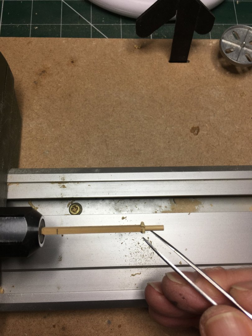
Once down to the required diameter it's on to files and sandpaper to achieve the final shape:
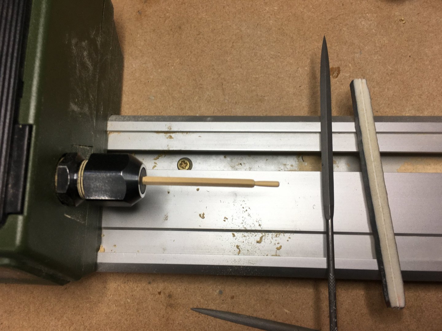
My trusty Vallorbe barrette file which I've mentioned elsewhere was ideal for filing right next to the square section without straying on to it. However I chose to file the corners off the square section as I think that looks better than a straight transition from round to square.
Next came the tricky bit - how to get the shaft round, given that I couldn't clamp the handle end of the oar without damaging it? Equally, I couldn't clamp the other end of the oar because then I wouldn't be able to pass the drawplate over the handle end. I decided the only option was to start the lathe with the drawplate already in position on the oar. To make this possible I started by rounding off the end opposite the handle. Again, it doesn't really matter where you clamp the oar at this stage as most of the remaining square section will be rounded. I've just made sure I've rounded enough of a length to fit in the collet for the nextstep:
Once this end was drawn down to 2.4 mm I took the oar out of the lathe and passed the round end through the largest (3.0 mm) hole on the drawplate before remounting the round end in the collet. This end is excess so marking the surface does not matter. This is where three hands would be ideal!

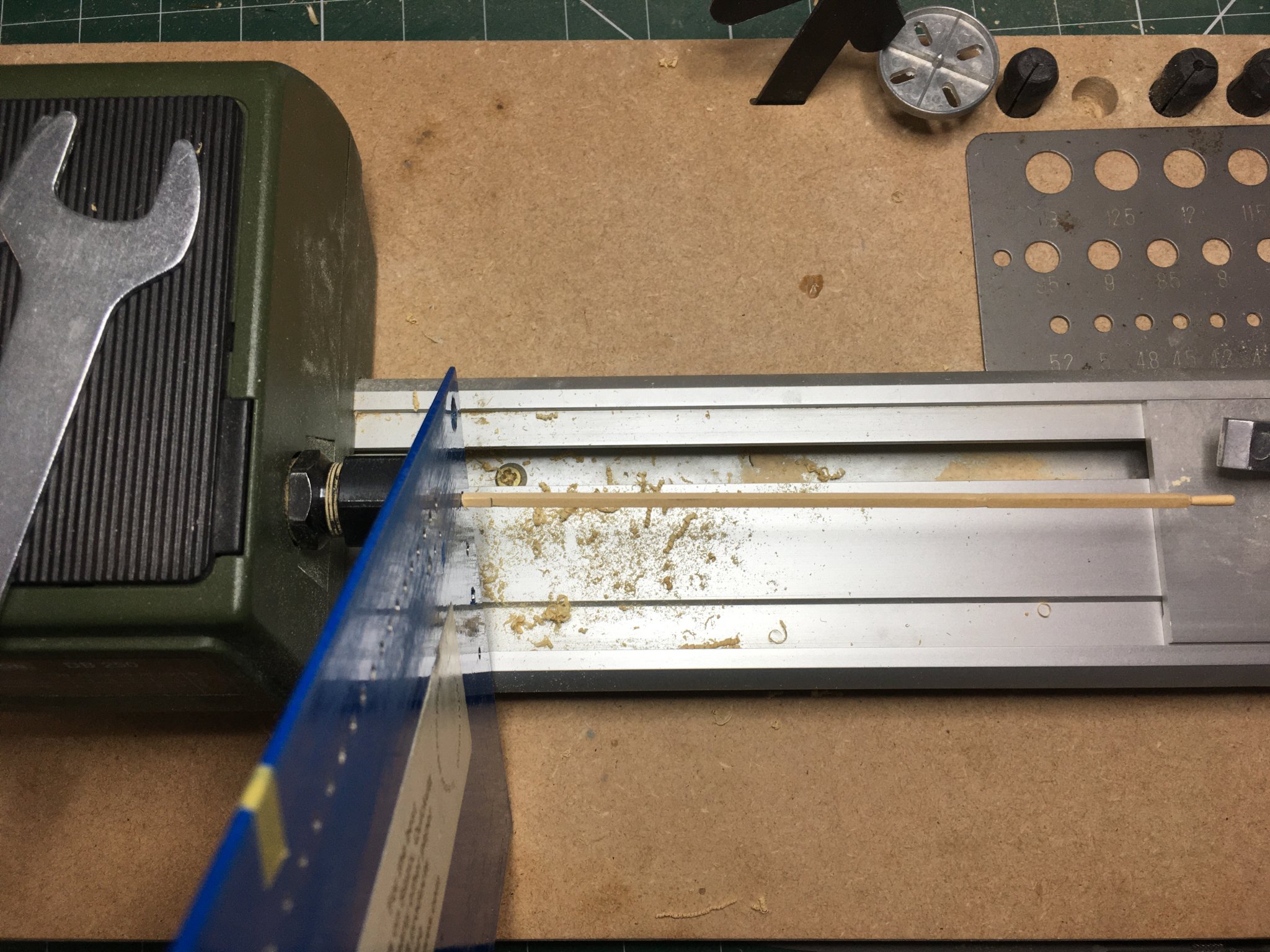
This time, the idea is to move the drawplate towards the tailstock, stopping at the pencil mark at the beginning of the section that will remain square. The obvious kink in the plan is that you have to dismount the work and remount it for each successive hole. However it doesn't take that long - I doubt if each oar took me more than three minutes to do all four holes on this section. Also, because revs are low and the work is small, you can support the handle end of the oar with your fingers with no discomfort at all:
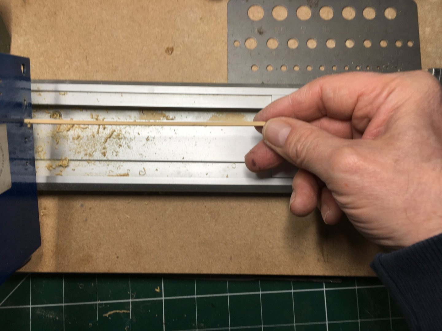
Incidentally, that isn't another drawplate in the photo above. It's a drill gauge which actually does work as a drawplate, but the hole sizes are too far apart and too large for most of my work.
Here's the end result of a few minutes work - the oar trimmed to length and waiting for the blade to be fitted. It hasn't even been sanded at this stage.

I hope folks found this helpful, and that it didn't come across as teaching granny to suck eggs.
It's taken 10 times longer to write up the log than to make the oars so I'm going to have to knock off now and leave the blades 'til tomorrow.
Derek
-
Hi again SpyGlass
I've now got to my PC and found the set I bought a couple of years ago, from Eternal Tools - here. To be honest, I don't use all the files in the set, and could probably have done just as well with one of the sets of 6.
Eternal also sell in the US and Europe. The following video gives a really good review of Vallorbe files, and might help answer some of the questions you and others have about the use of the different file types.
Hope this helps.
Derek
- Richard44, Ryland Craze, sirdrake and 1 other
-
4
-
Hi SpyGlass
On my mobile so can’t find record of set I bought - I’ll try tomorrow. However, if you just get one file I’d recommend a barrette for the reasons I’ve mentioned. See here. #4 cut is a good choice for very fine work; #2 cut is coarser and therefore removes material faster but still gives a very good finish. The site I’ve pointed to has a bewildering array of files.
My set has 12 which is most of what I’ll ever need. The only additions I might possibly go for are slotting files - very fine files that jewellers use for cutting slots in small screws, and maybe some rifflers - the ones with curved ends for filing in awkward places. But I just like collecting tools!
Derek
-
That’s great Richard. At this rate I’ll have to ask Vallorbe for commission. I got a mixed set of Their files, #2 and #4 cut, and that’s given me all the files I need (so far!).
Derek
Btw I think rifloir is the same as riffler
-
Great! Glad to help. I've gradually tried to replace my 'cheap & cheerful' tools with quality versions - the investment is always worth it. Like your paint job, btw.
Derek
-
Looking good. I've not seen the masking tape idea before - I found the youtube channel you mention but there's loads of videos. Any idea which one covers tape? As an alternative, I find shrink wrap tube useful for these sorts of jobs - cut a slice off an appropriately sized tube apply a heat gun and you're done. I got about 100 year's worth of black tube from Amazon for peanuts.
Derek
-
-
Thanks as always for the comments and likes.
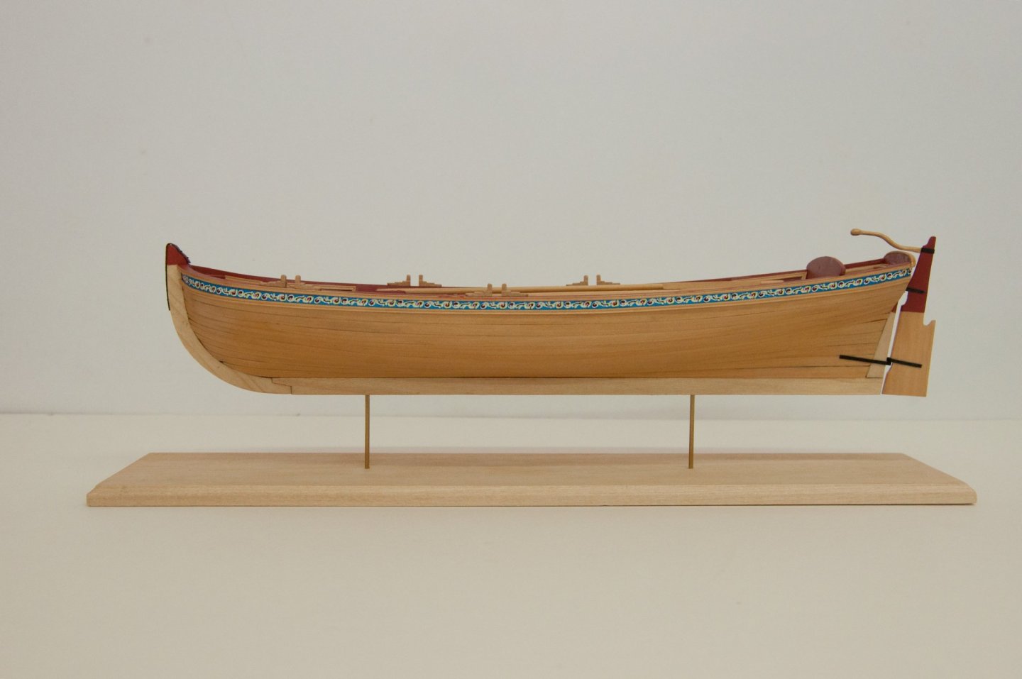
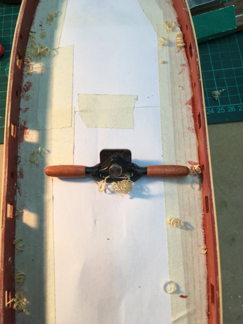
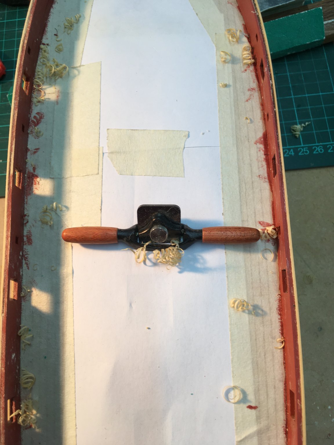
I'm still working on the outer bulwark planking, trimming the gun and oar ports. The miniature veritas spokeshave was ideal for trimming along the top of the bulwarks:
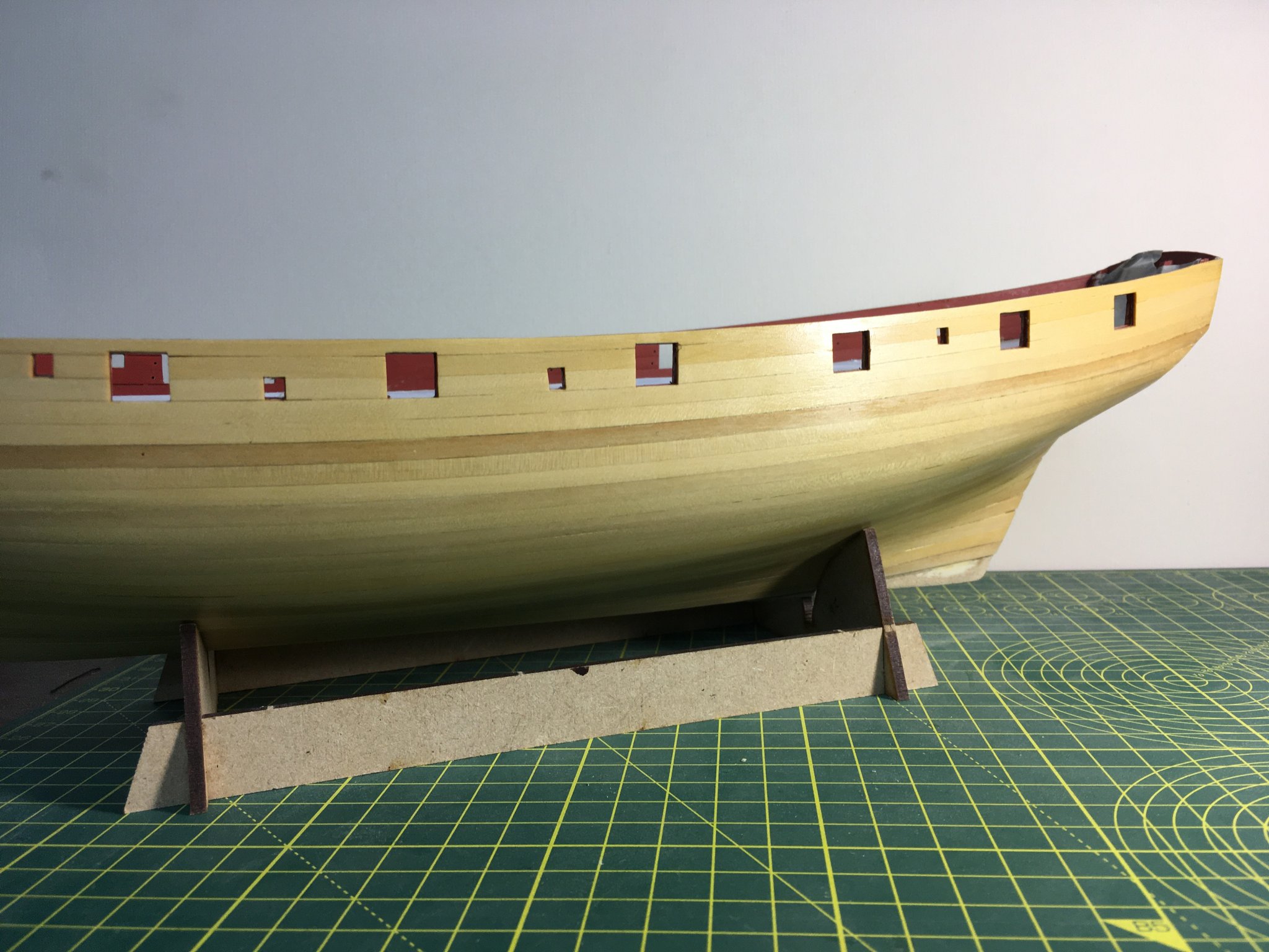
Trimming the ports was an exercise in care. I used the same tools as for the inside planking, but the outside will show more and there are no fancy decorations to cover up rough edges. Once I'd trimmed the ports I gave the hull a quick coat of shellac to reveal any spots still needing sanding:
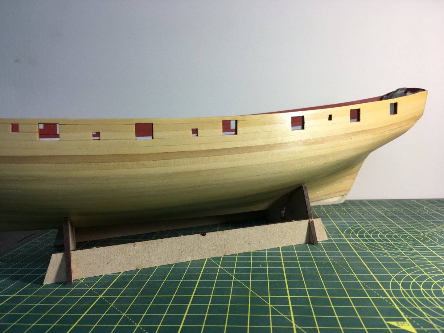
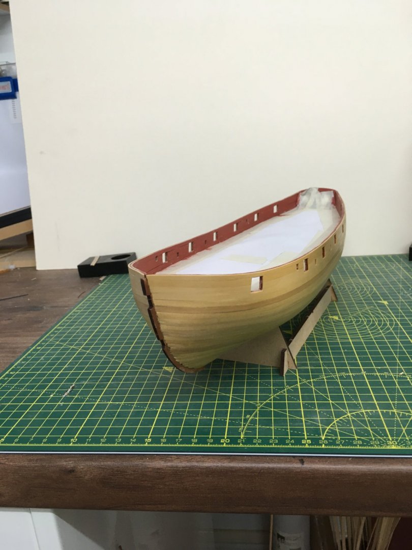
On the whole I'm reasonably pleased. Probably some work still needed around the bows, but not too much when you consider the amount of coppoering.
Next, I tackled the wales. I took Chris's advice and used PVA and pins for these strakes. I'll paint the wales so the pins are not a problem. However, although the pins supplied with the kit were good for the first planking, I found they weren't beefy enough for boxwood, even with pilot holes. I used slightly larger pins - 0.7mm as opposed to 0.5mm, and they were fine. I also used Super 'Phatic glue as recommended by Glenn (Scarborough Glenn, I think, not Texas Glenn) and that also seemed to work fine. It was certainly easy to apply with the supplied nozzle.
Finally, I attached the prow, keel and sternpost. Here's the prow being glued:
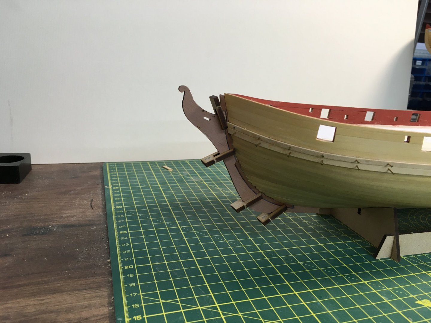
This is another good example of Chris Watton's attention to detail - the four pegs supplied in the kit make it easy to ensure the prow is perfectly aligned as it dries.
The time for coppering approaches! All I need to do is mark the waterline and make sure the hull is smooth - I need to fill in some gaps around the keel and sternpost. I'm grateful to other folks' logs for showing me how careful I will need to be in marking the waterline accurately.
Derek
- ccoyle, Edwardkenway, VTHokiEE and 10 others
-
13
-
-
Here's what I wrote in my Speedy log in response to the same question:
"I've had a word with Chris, and he decided to go with vertical planking on Speedy based on his research which found many contemporary model pictures showing similar sized and period models with the stern planking running vertically, not horizontal or angled. Looking at my copy of the AOTS book on Alert I noticed that the transom had horizontal beams as well as vertical frames. The Alert book showed the transom planked horizontally, but depending on how the beams tied into the frames I imagine vertical planks would be just as possible as horizontal. I'm going to leave the planks as they are, mainly because of Chris's research, but also I quite like the alternating pattern of vertical-horizontal-vertical".
Derek
-
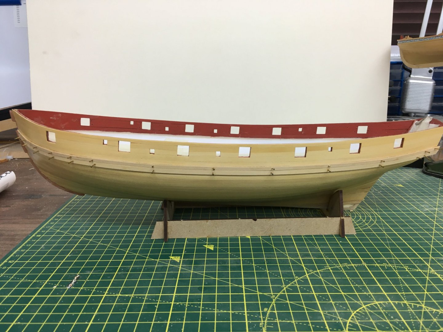
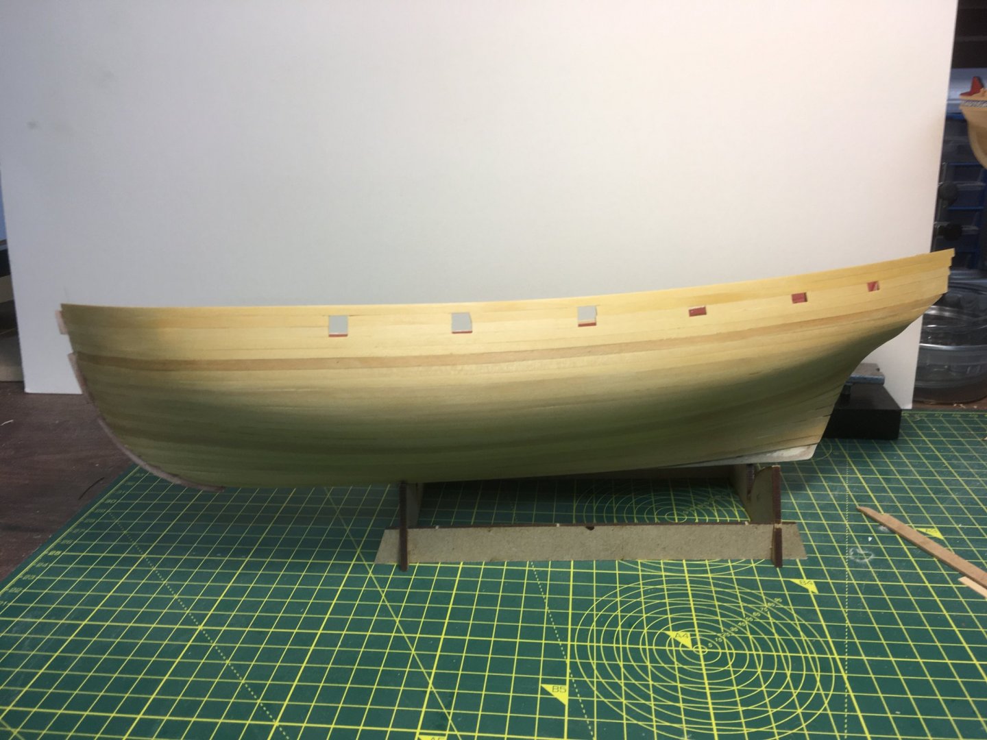
I've finished planking the outside of the bulwarks, and decided to give them an initial sanding before trimming the gun and oar ports:
Apologies for the picture quality.
Derek
-
Looking good! The sanding shows how well you laid the second planking.
Derek
-
-
I like the idea of a strip along the edge of the copper. Another idea I’ll borrow!
Derek
-
Bob
Thanks for a great review. Amazon won't ship it to the UK but I've ordered a copy from ebay. The only downside is that shipping adds another $35. I still think it'll be worth it.
I came across a description of Antonio's workshop some years ago in Milton Roth's book, Ship Modelling from Stem to Stern. I was greatly impressed by his use of mobile workstations, and although that's not practical in my workshop (which I'd already fitted out with fixed units) I've used the idea in the garage. There I have four mobile benches of various sizes for different machines, including two 6' benches that I can line up when using my Syren Rope Rocket. When not in use they fit neatly against the back wall behind the cars.
Thanks again
Derek


HM Brig-Sloop Speedy by glennard2523 - Vanguard Models - 1/64
in - Kit build logs for subjects built from 1751 - 1800
Posted
Thanks Glenn, that's very helpful. I tried to get references for the waterline from the plans and photos in the manual. I've not drawn the line yet, but when I put a laser level on the three reference points I'd marked they lined up well. However I like your idea of using the rudder as the primary reference, and shall check my points against that. If the plans are accurate I shouldn't be too far off.
Thanks also for explaining your technique in more detail - very useful for a newcomer to copper work.
Derek