


DelF
-
Posts
1,409 -
Joined
-
Last visited
Content Type
Profiles
Forums
Gallery
Events
Posts posted by DelF
-
-
-
Vane: Ok, that’s helpful. I guess I was over-thinking it.
Bob: thanks. I’ve used Chuck’s edge bending techniques on other builds but I don’t think it would work on the gun port pattern as it’s too wide (see Vane’s picture above). However Vane’s advice is that it shouldn’t be an issue so I’ll get on with it tomorrow.
Derek
-
Hi Vane,
I hope you are still enjoying your holiday in the sun. I've been following your Speedy log with interest, and have just started my own. I have got to the stage where I need to fit the gun port patterns, and want to make sure I get it right. Like you, I use a hot air gun to bend wood, and I don't think I'll have a problem bending the patterns round the curves from bow to stern. However it looks like the strips will also have to bend widthwise (ie top to bottom) in order to follow the curves of the bulkhead frames, especially around the bow area. In the instructions Chris advises clamping the strips to the top of the frames and using pins to keep the bottom edges tight.
Did you find that this was sufficient to keep the patterns in close contact with the frames? When I tried a dry fit I found it very difficult to keep the bottom edges of the patterns flat against the front few bow frames. I'd be grateful for your thoughts before committing any glue - the last thing I want is an ugly 'step' that would throw the subsequent planking.
Derek
-
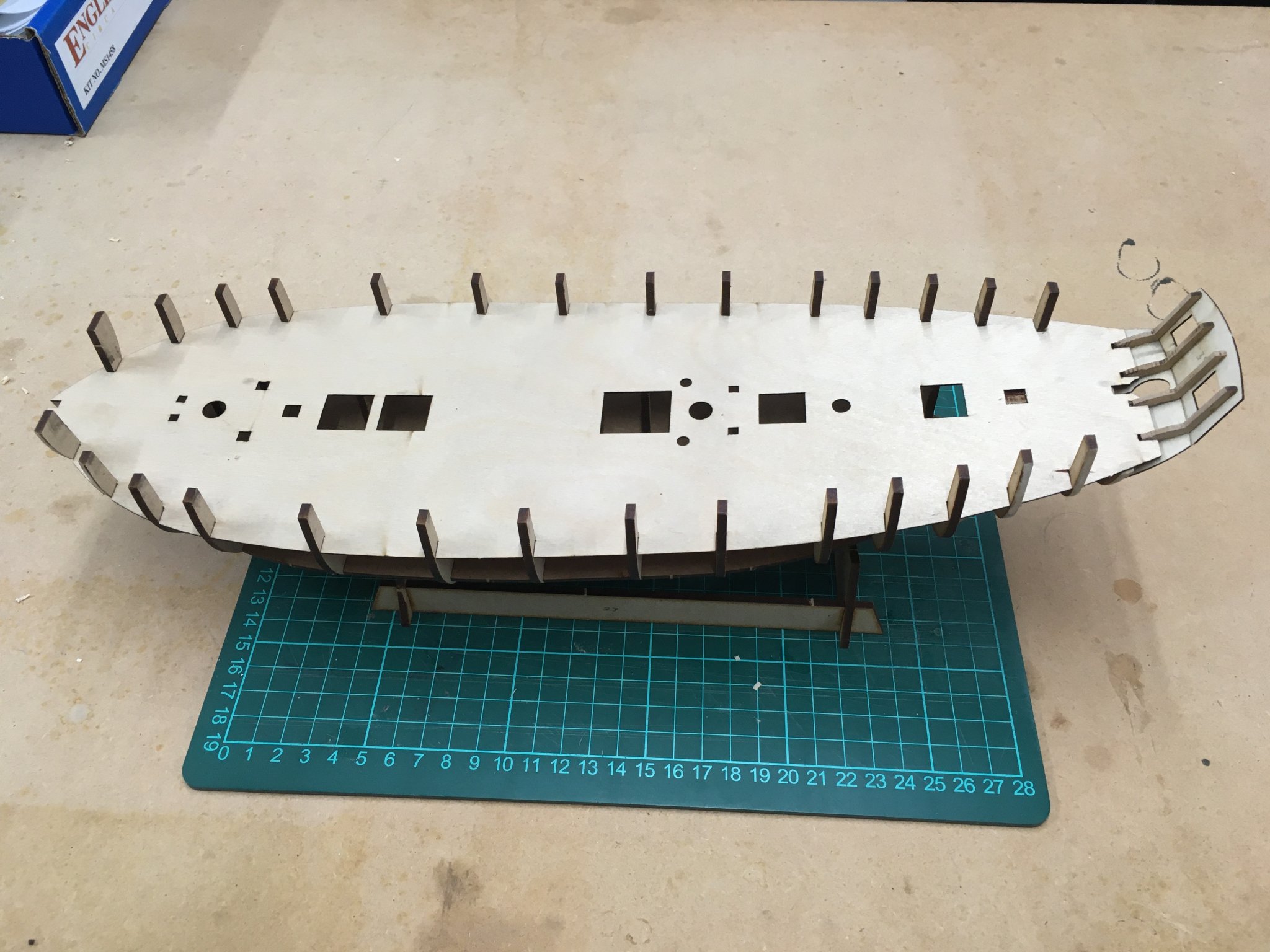
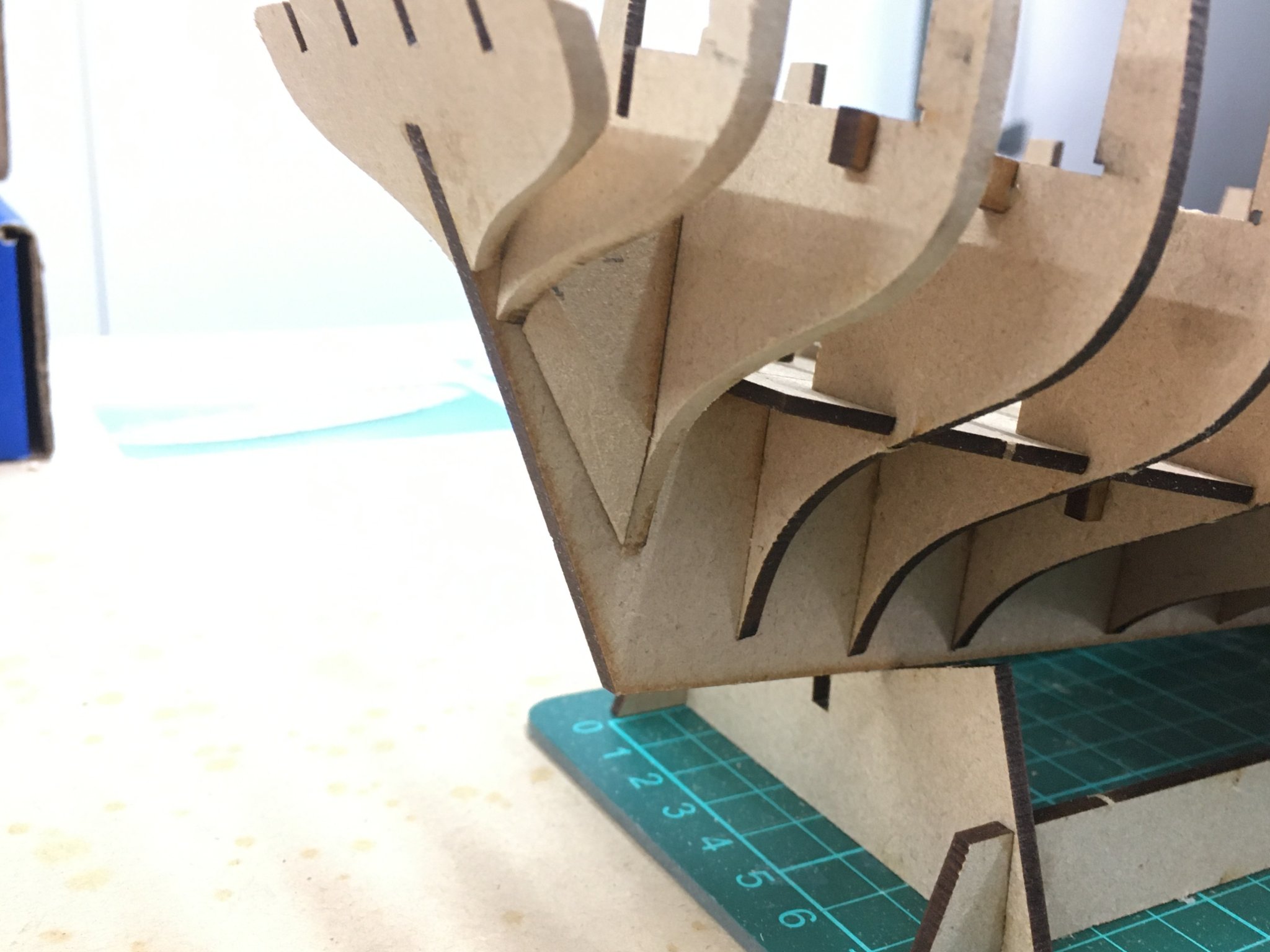
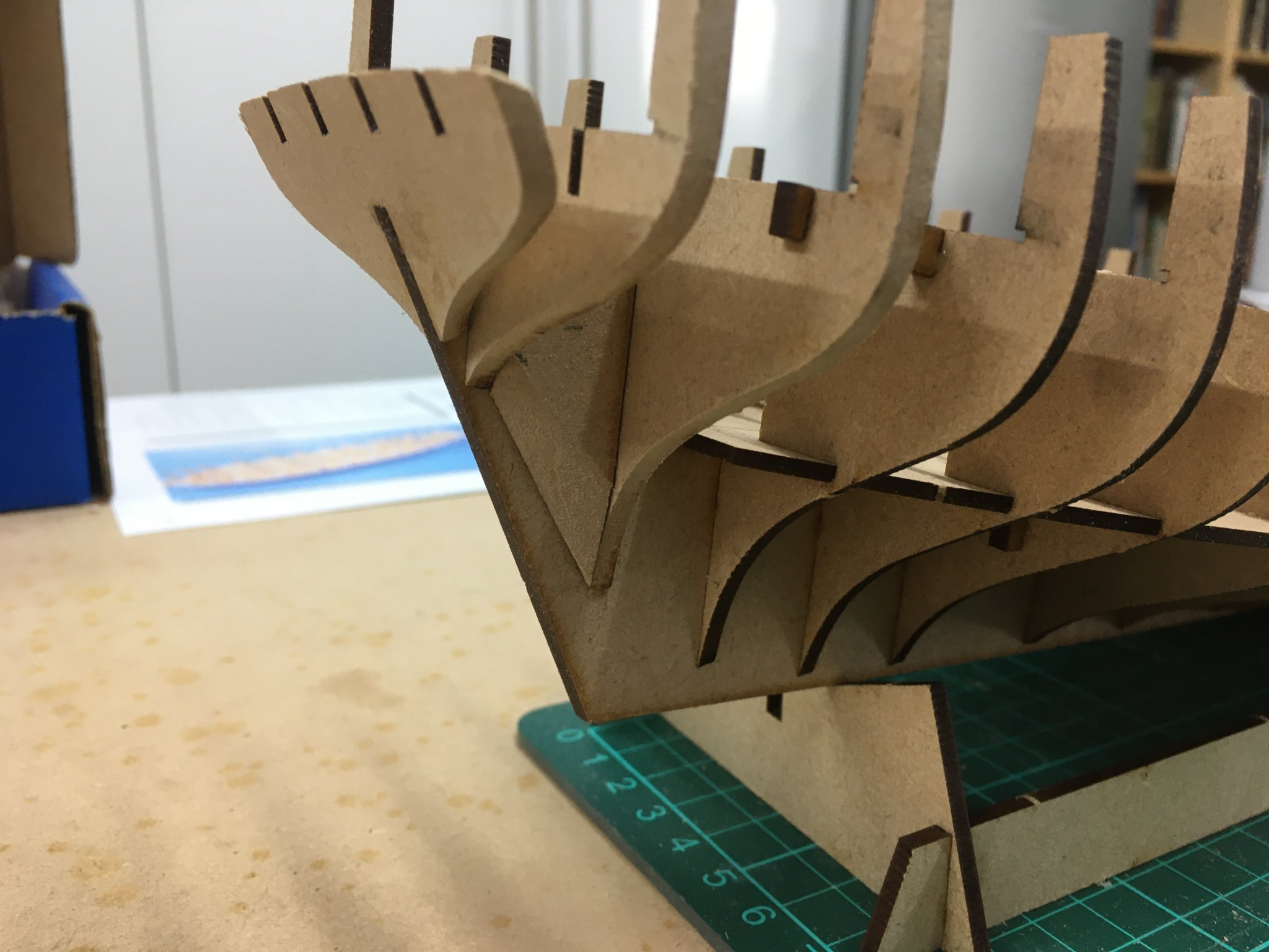
The upper deck went in fine. The fit was very precise, as it should be, but of course that means there is no wiggle room so to get it in place you need to gently bend it edgewise to squeeze it between the bulwarks. This picture shows the deck when I'd got it about half way down towards it's final position. A bit of final wiggling and the slots in the deck fit neatly into those in the bulkhead frames.
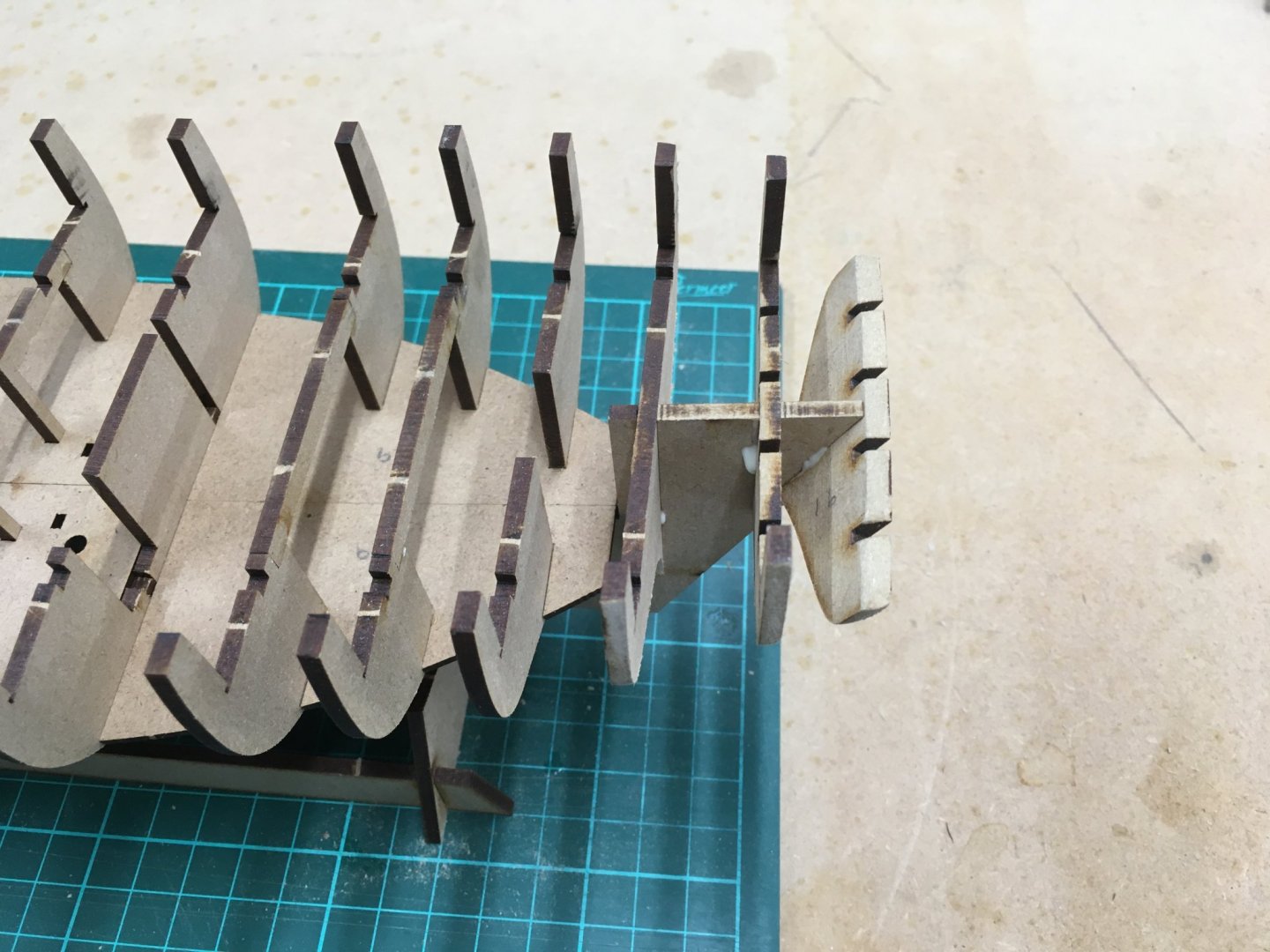
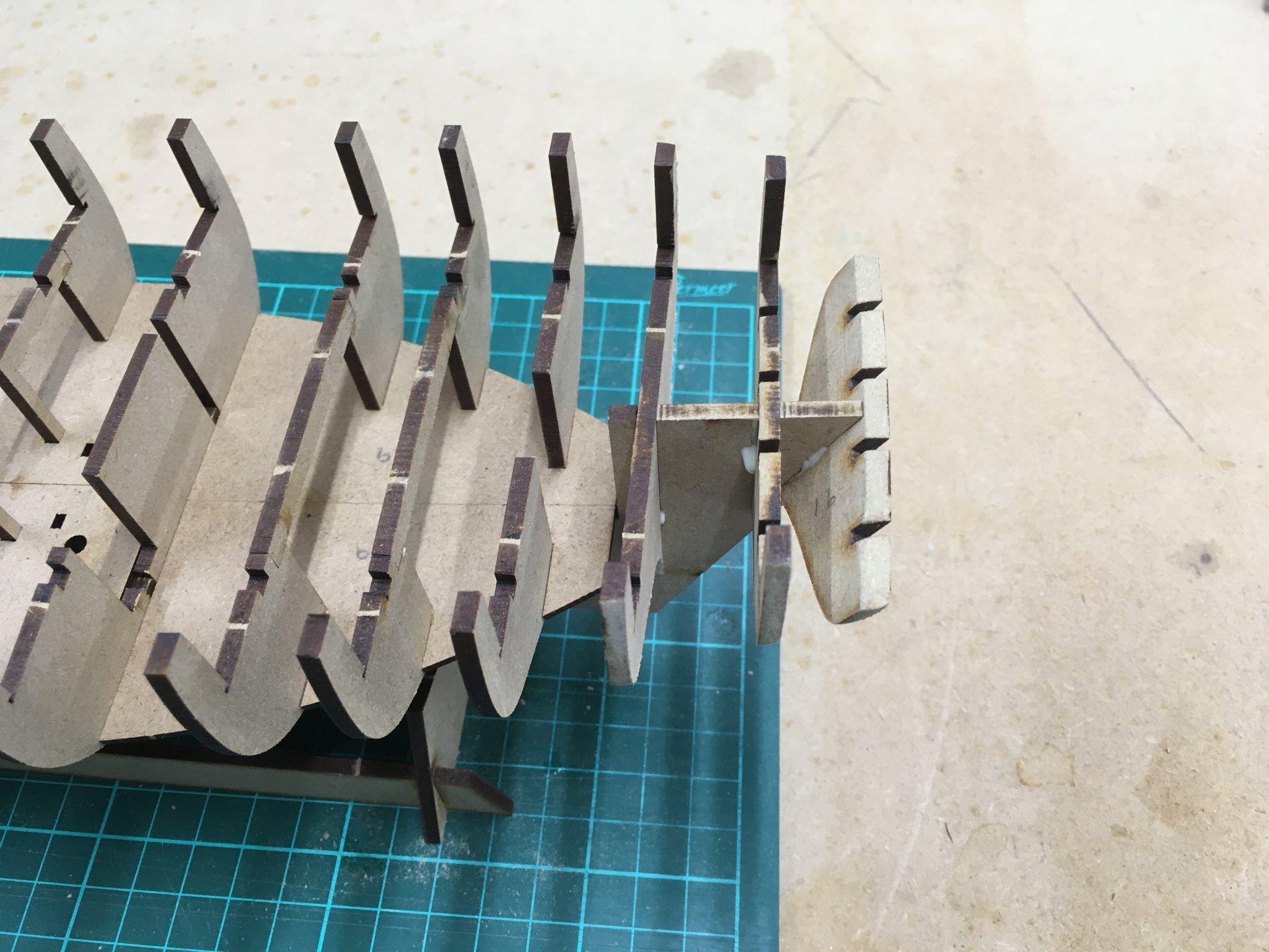
The trickiest part of the job is trying to avoid catching the four delicate stern frames. These are just asking to be snapped off if you're not careful, so the next task is to fit the stern counter and the stern board. The next shot shows how these components protect the frames from accidental damage.

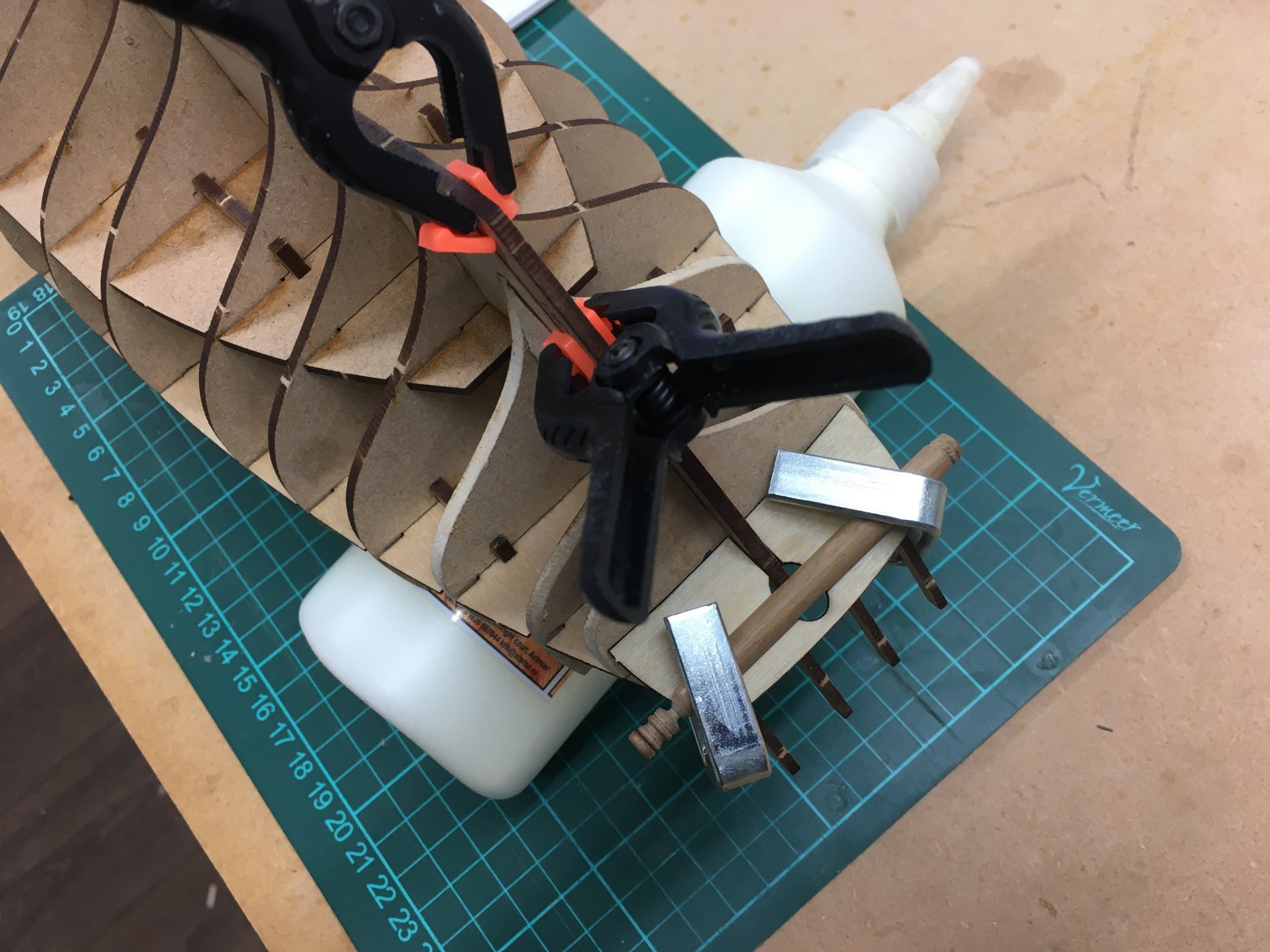
I tried clamping a round dowel to the stern counter as it dried to try to encourage it to follow the slight concave curve in the underside of the frames. On reflection I should probably have tried to introduce the bend in the counter off the model, with perhaps with heat and steam, as I'm not sure the glue will hold it long term.
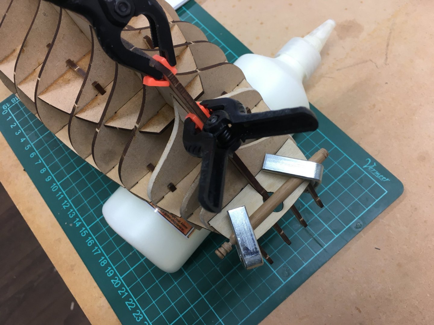
Next task is fixing the four gun port patterns. I'm not looking forward to this as these thin but wide strips of wood need to bend in at least two dimensions to fit tightly against the frames.
Derek
-
I couldn't resist the temptation after receiving the Speedy kit for Christmas. Despite promising myself that I wouldn't start the new model until I'd finished at least one of my other two current projects, I soon gave up pretending I could keep my hands off it and plunged into the build. I've started a log here Derek's Speedy Log. Early days yet and I don't want to repeat what I've already said in the log, but I'm already struck by just how much I'm enjoying constructing a kit that seems to require little or no bashing. For years I've been moving away from pure kits towards scratch building and for a long time I thought one of my next projects would be a complete scratch build (with Chuck's Winchelsea Group as a significant step along that route). However I think a lot of my dissatisfaction with kits is that so many are poorly designed and constructed, historically inaccurate and with poor quality materials and woeful instructions, that you have to make up for their deficiencies with a great deal of scratch building and research. The end result is very satisfying, but while you're actually turning boxwood rulers into hundreds of blocks (for example) it can get tedious, to say the least.
Although it's early days I've found Chris's kit to be the opposite of the ones I've described above. So far it's been a joy to build, everything fitting together perfectly with clear instructions and photographs. I've actually found working on Speedy for the last couple of days very relaxing, to the extent that has motivated me to crack on with my other projects as I wait for glue to dry on the new model.
It remains to be seen if I still feel so positive when I start on the planking!
Derek
-
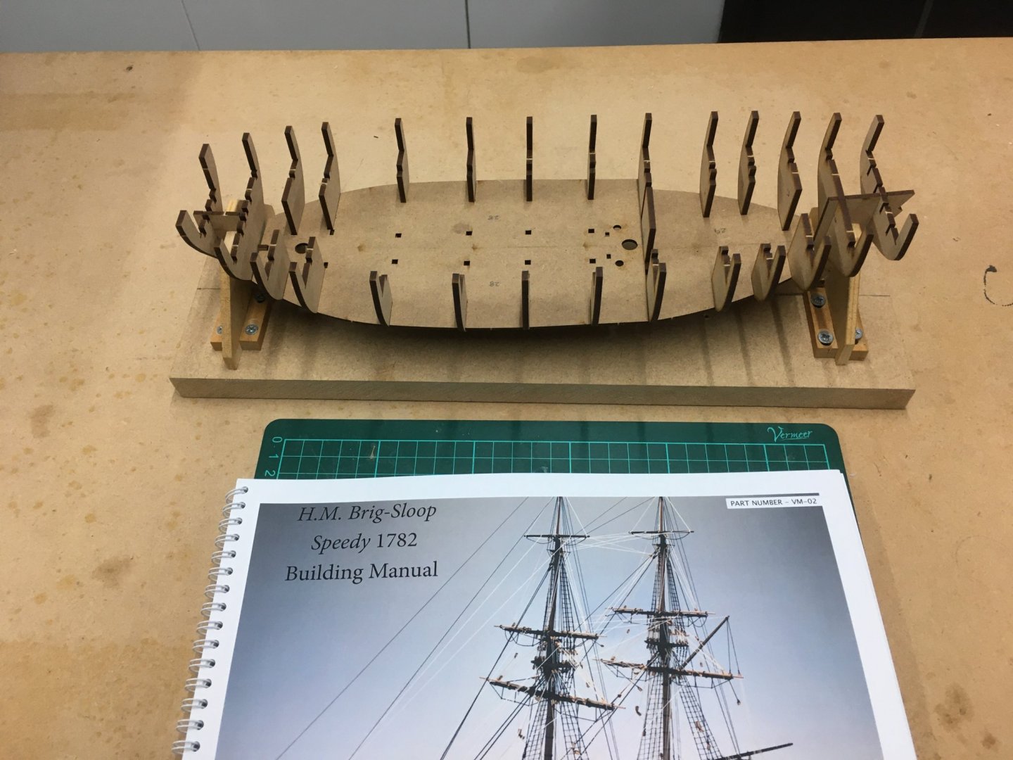
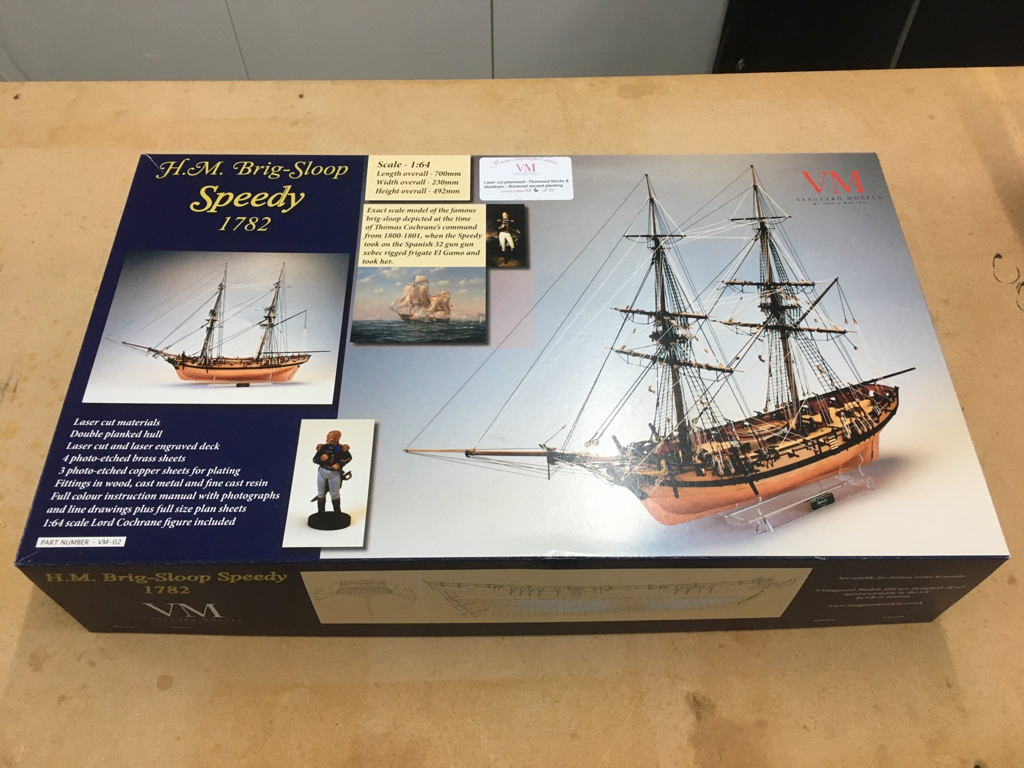
After receiving the new HMS Speedy kit from Vanguard Models as a Christmas present I was determined to leave it in its box until I’d finished off at least one of the other two model projects currently on the stocks. However as soon as I opened the box I knew I was going to have a hard time resisting the temptation. Chris Watton has done a great job in producing this, the second ship in his new range. I went for the limited edition Model Shipwright version, with boxwood second planking and a host of other goodies. There’s a wealth of information on the kit and its development elsewhere on the forum (Vanguard Models news), and in the first Speedy build log Vane has summarised information about Thomas Cochrane and his famous ship (Vane's Speedy log) so I won’t repeat all that here.
Suffice to say, everything about the kit oozes quality.


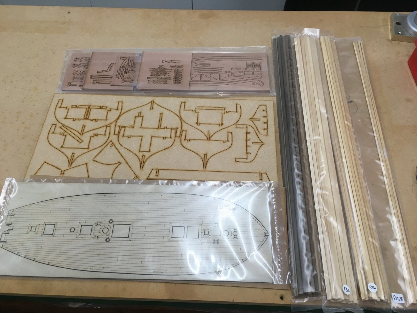
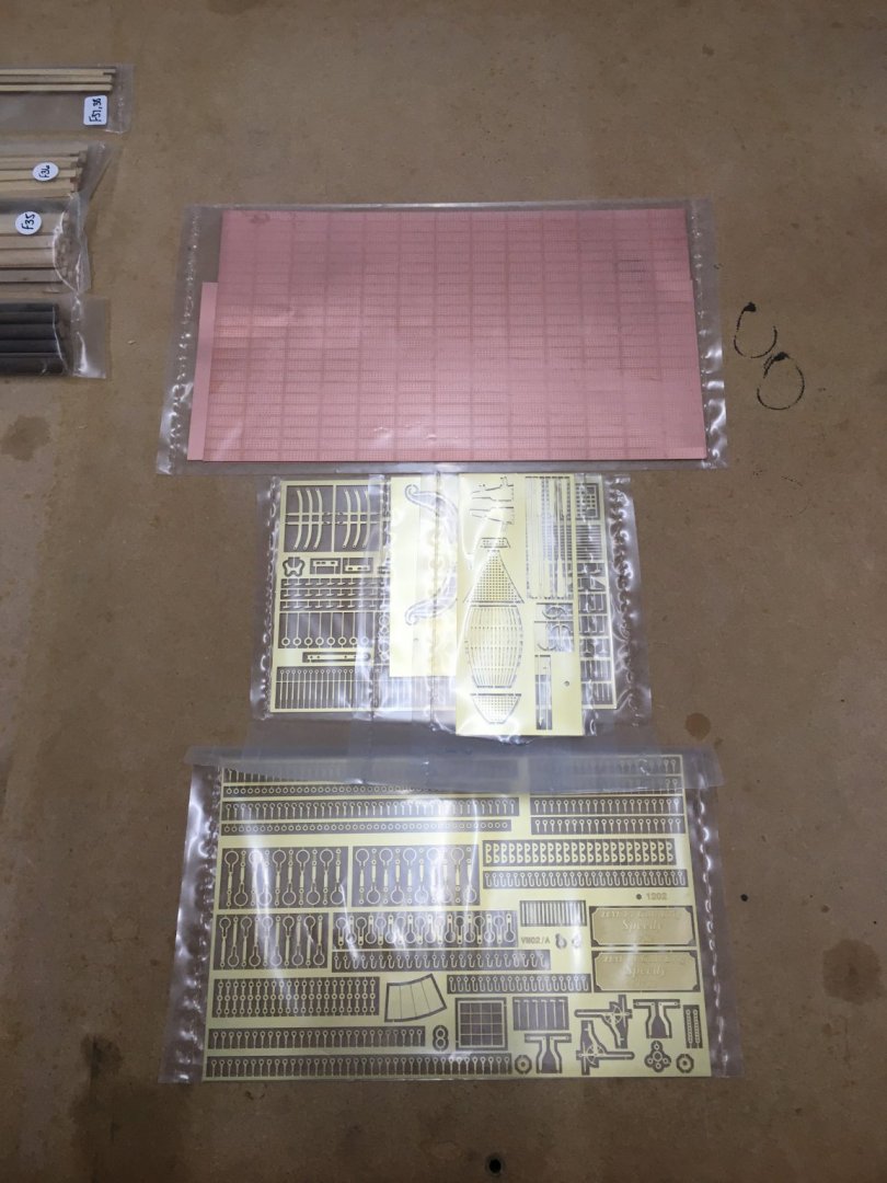
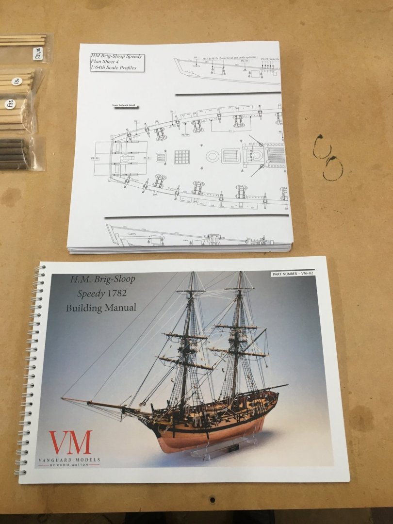
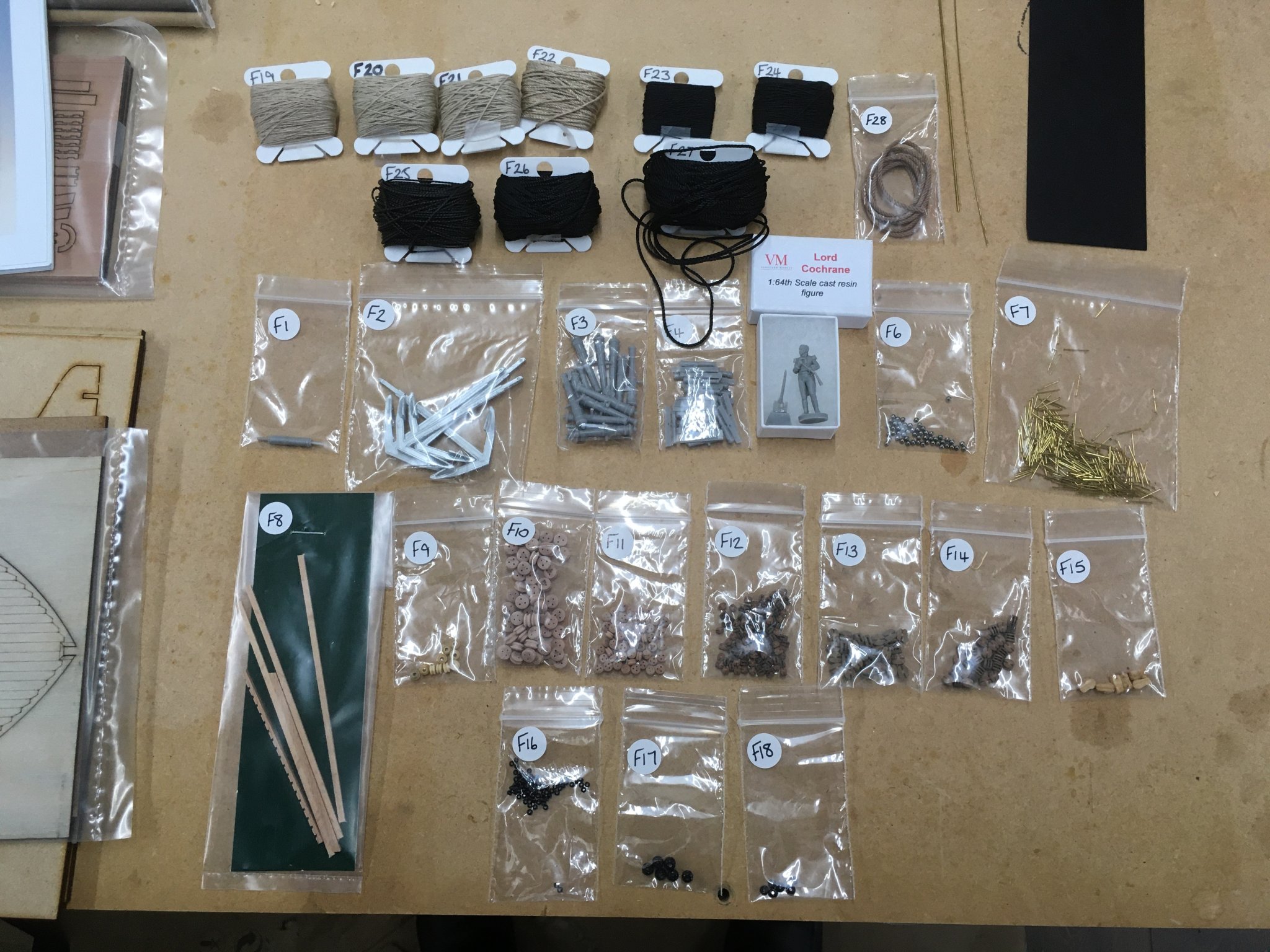
Everything was well packaged and labelled, and supported by ten sheets of plans and a full colour build manual. The sheer number of parts was eye-opening, especially for such a comparatively small vessel. The parts list itemises nearly 1,000 individual photo-etch components - 1,433 if you include the copper plates. Plus of course hundreds of other metal, wood and resin items.
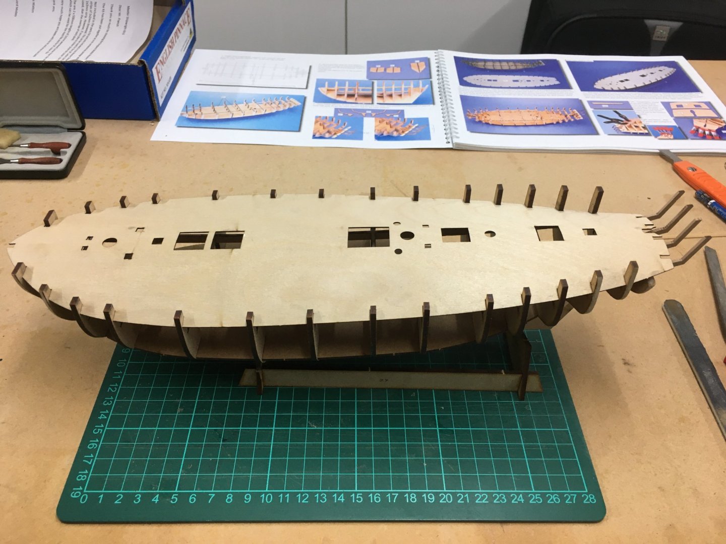
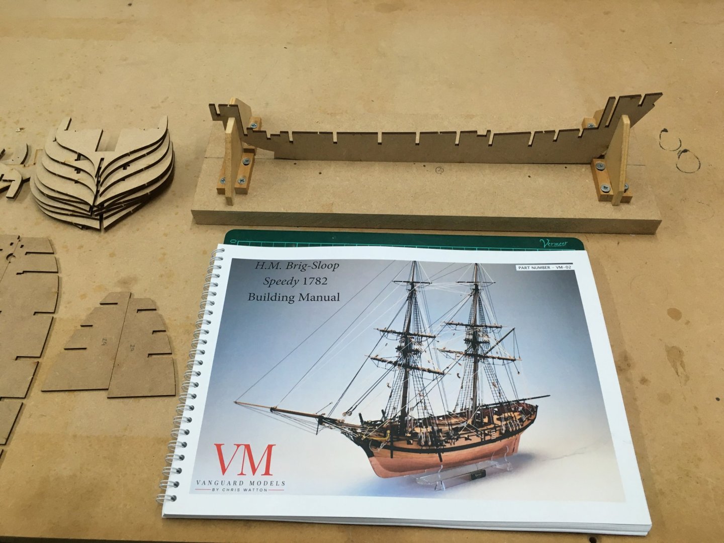
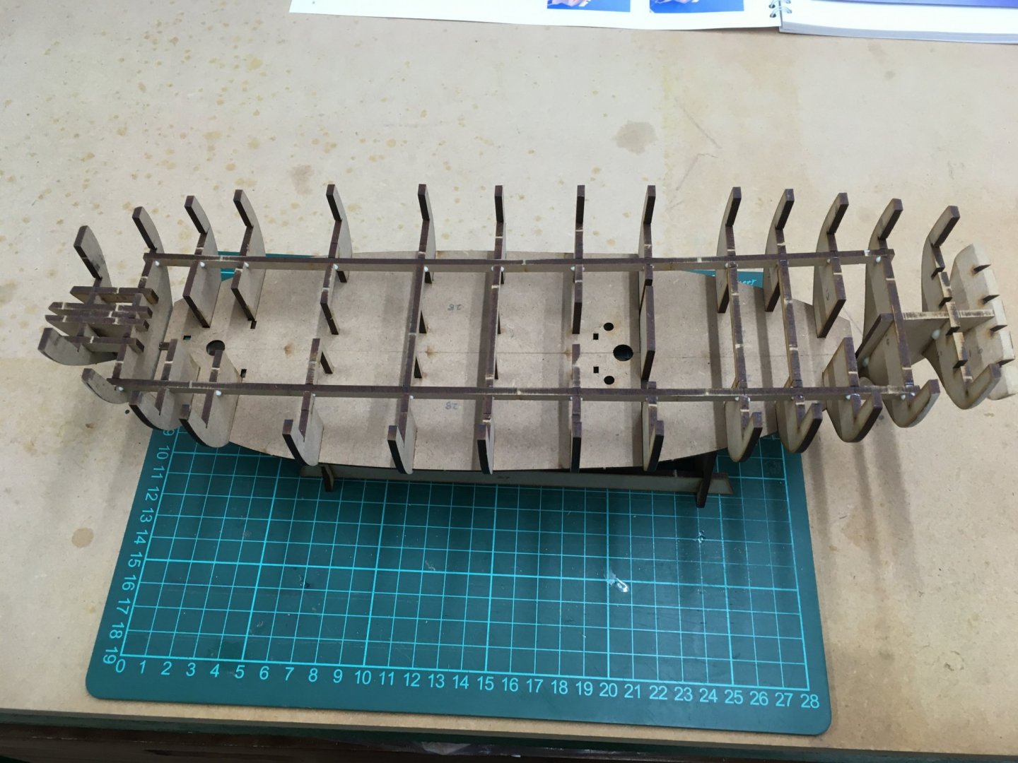
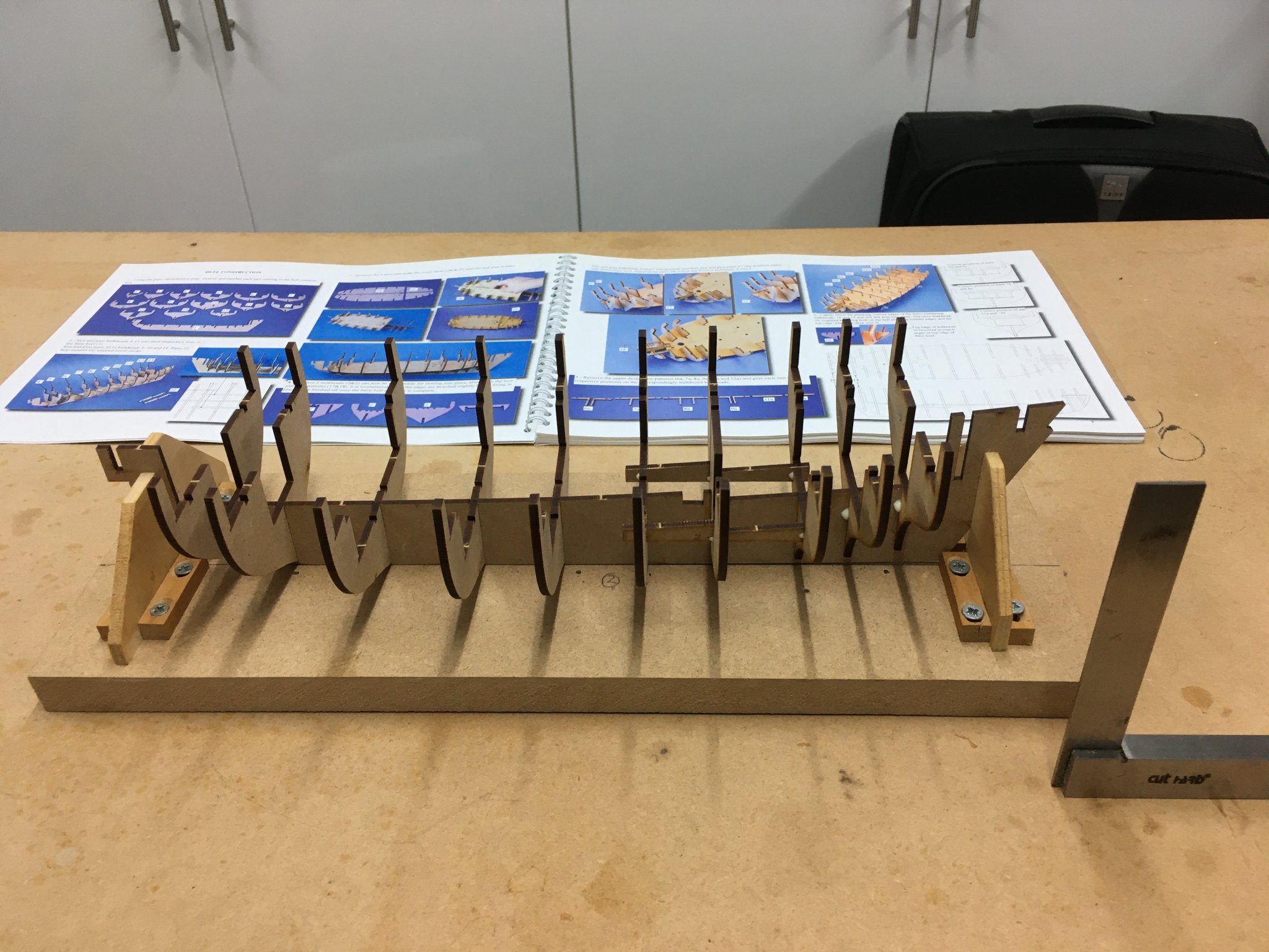
The first sign that my determination to be patient was crumbling was when I decided to knock up a building board just to be ready when I needed it. Needless to say, the sight of the building board sitting there on my workbench asking to be used quickly eroded further resistance, and I started construction yesterday. I quickly realised that the building board was more or less redundant. The frames were all a good fit on the false keel with zero sanding, and once the lower deck and the various longitudinal beams were added, the whole structure was perfectly straight, square and rigid.

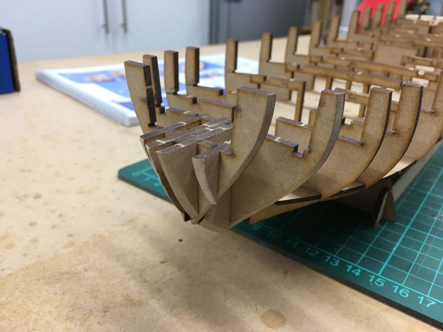
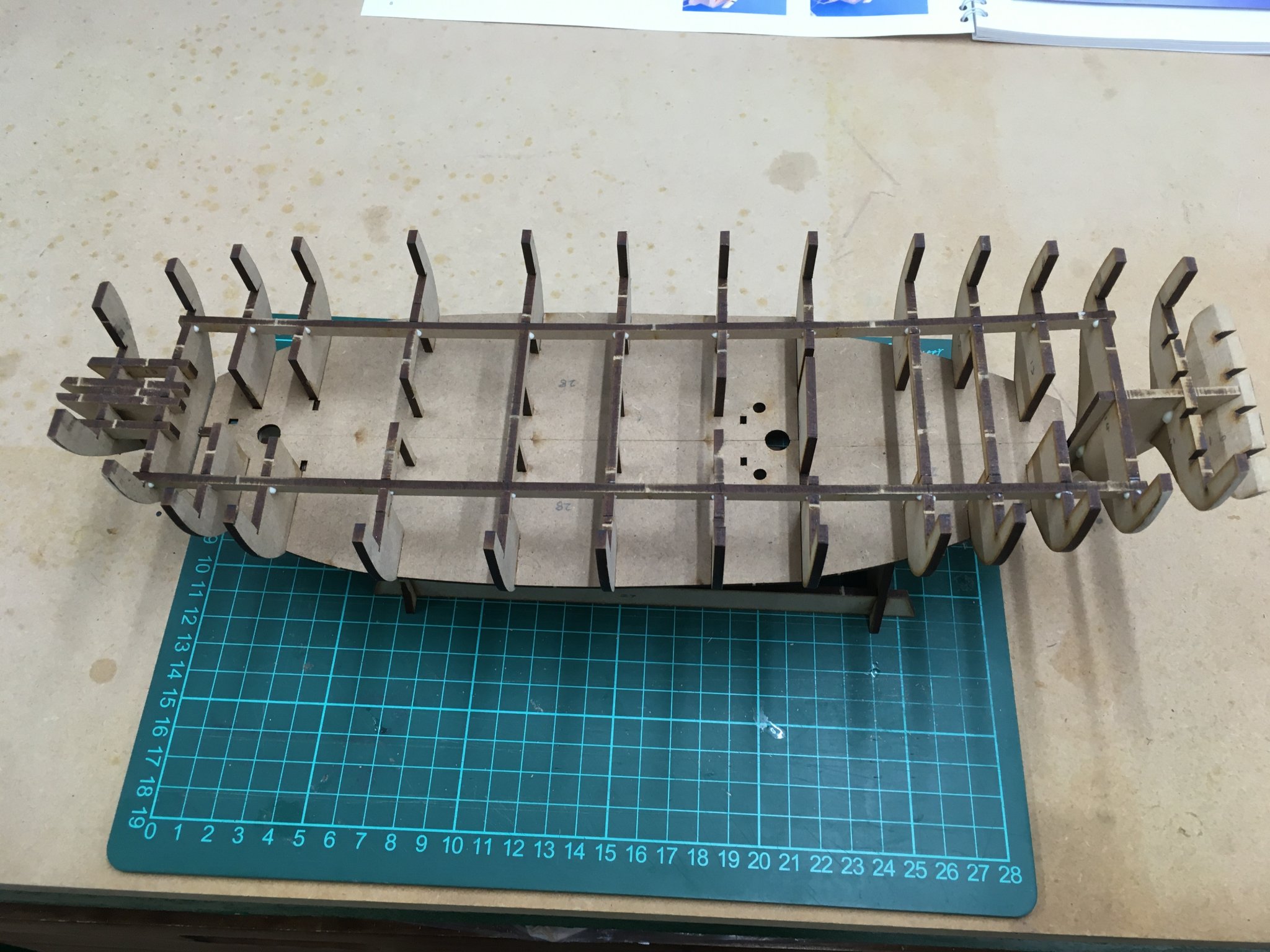
Once the lower deck is fitted, the next task is to attach the last few frames at the bow and stern. At first I was a bit dubious about Chris's advice on these, which is to do the initial bevelling off the model. However in practice this seems to work well, particularly on the half dozen filler pieces which would have been difficult to fair in situ.


Today I’m going to crack on with the upper deck and various tricky timbers in the stern.
Derek
-
Thanks Steve. The drum works quite well on the midships area but is more awkward nearer the bow and stern. I’ll try a disc in those areas.
Derek
-
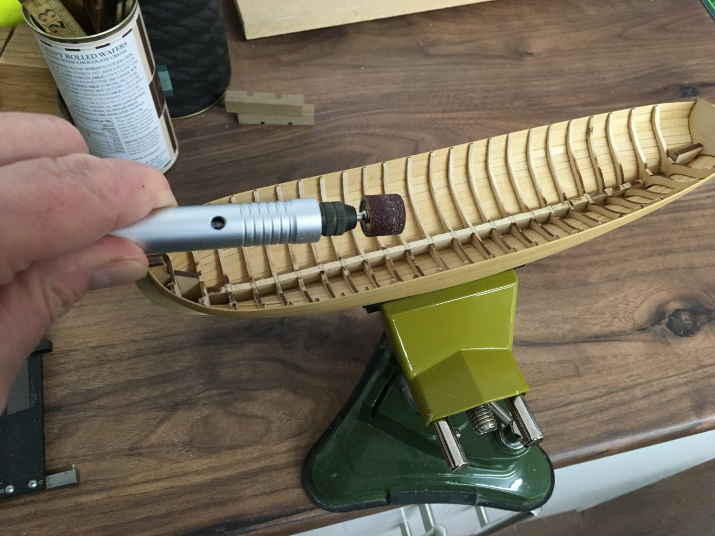
Happy New Year everyone!
Thanks Meddo. Here's a picture of the flexible shaft attached to my Proxxon drill, which I use to get into tight places. The sanding drum shown here is the largest I'm using on this job - there's a range of smaller ones you can get for different tasks. A handy tool. The only downside is the shaft which tends to get in the way - ideally I'd like a cordless tool of a similar size. Does such a thing exist?
I don't think I'll be getting much time in the dockyard for a few days. I stepped on the scales today
 and I think I'll be spending the next week or so in the gym, digging in the garden, walking the dog, and every other thing I can think of to get the excess pounds off.
Derek
-
I agree with No Idea. I’ve used Exotic Hardwoods several times and been very pleased with their boxwood.
Derek
- paulsutcliffe, thibaultron and mtaylor
-
 3
3
-
I just wanted to thank you for this recommendation. As a fan of maritime fiction (and non-fiction) and sci-fi/alternative histories I thought this series would be right up my street and I was not disappointed. I've nearly finished the first volume and if Taylor Anderson keeps up the same standard I'm looking forward to the rest of the set. I agree it's not high literature, but I like his style and he delivers good plot lines, characters and descriptions. What more can you ask of a good escapist page-turner?
Derek
-
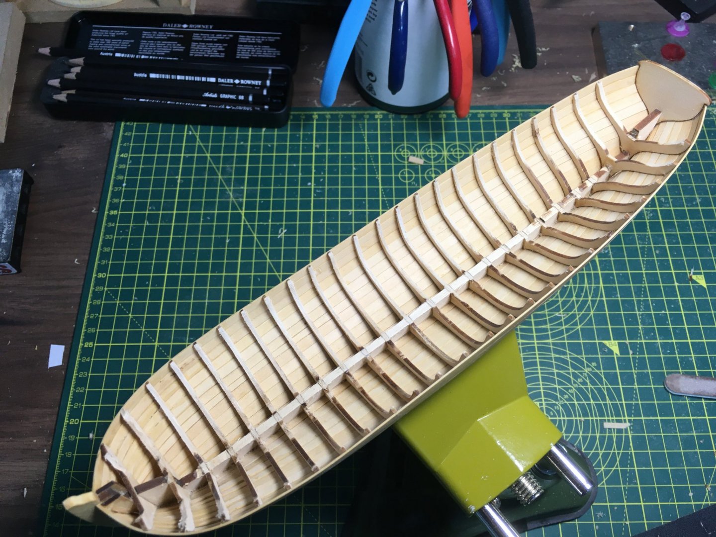
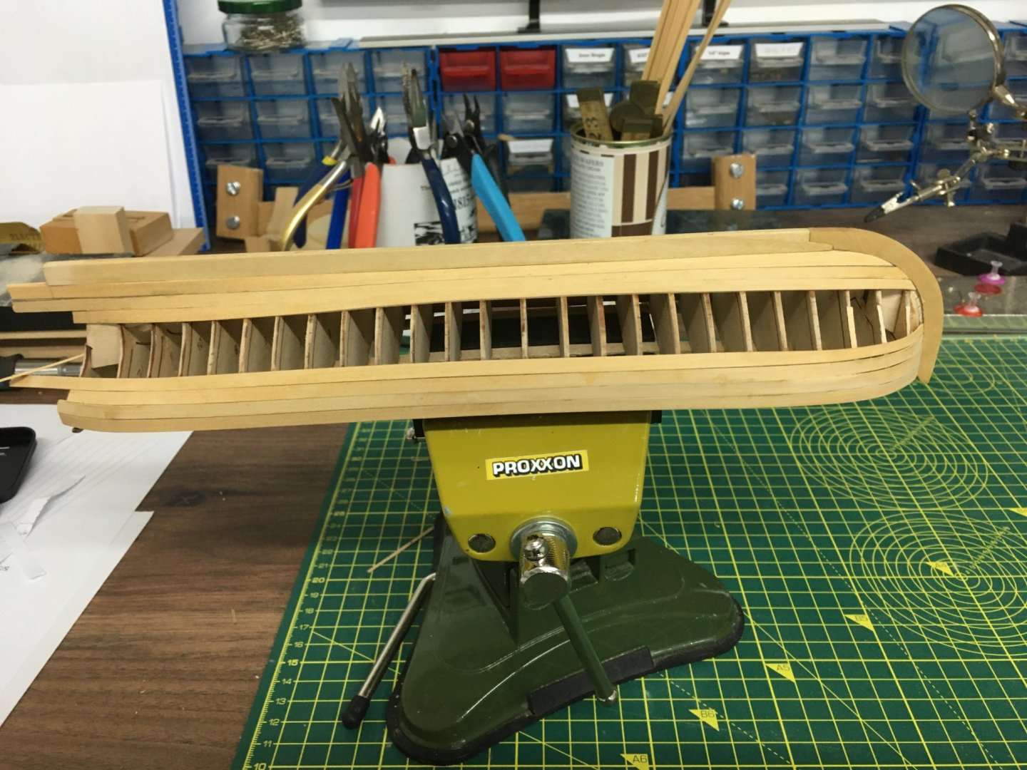
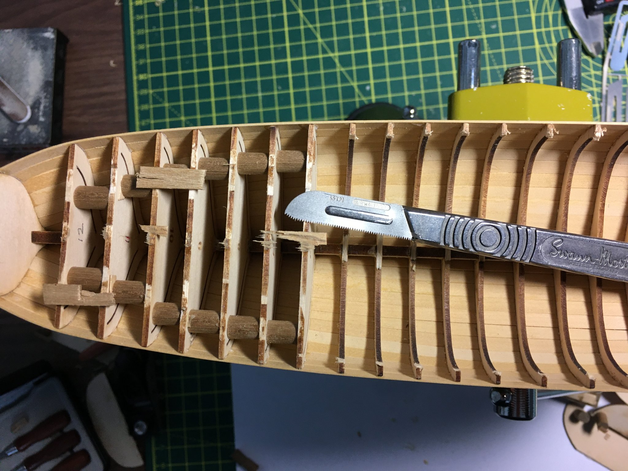
Well, Santa came up with the goods and I'm itching to get on with the Speedy. I've reported elsewhere on just how chuffed I am with the new kit (Chris Watton & Vanguard News). However I'm determined to finish this little kit before I get engrossed in the new one, so now that the main festivities are over I've been able to get back to the dockyard for a couple of brief visits. I'm relieved that the external planking is finished, the first post-Christmas task being to remove the middle of the frames:

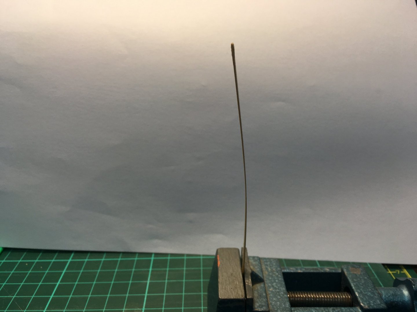
In the build manual Chuck recommends using a file to make the short cuts required to remove the frame centres. I found this too tricky and time consuming. I read in Blue Ensign's log that he'd used a saw-toothed scalpel blade. I remembered I've had a photo etched sheet of these lying around for donkeys years, thinking they'd be too wobbly to be of any use. To my surprise the 45 tpi blade shown above was perfect for the job and made short work of the frames. I'm glad I only glued one end of each of the round spacers I'd used for stiffening as it made removing the frames a doddle. Thanks again to MikeB4 for this tip.
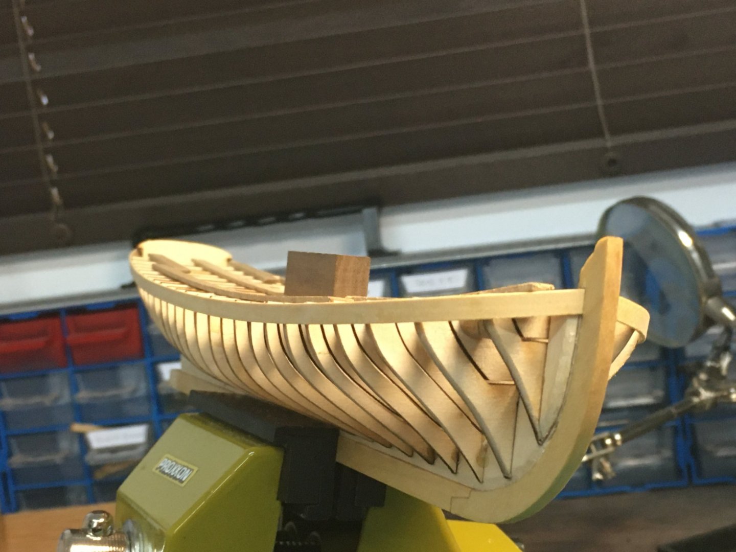
Next I started cleaning up the frames, the aim being to reduce their thickness to about 1/32" (0.8mm) at the sheer gradually thickening towards the bottom. This is as far as I've got.
First pass down the starboard side went quite well although I'll do at least one more pass to get all the frames to the required profile before moving to the port side. Chuck recommends using sandpaper, but again I found I was getting nowhere fast using hand sanding so I (nervously) resorted to a power tool. After a couple of tests I decided to use a small sanding drum in a flexible shaft attached to my Proxxon drill (I'll post a photo next time). I settled on this as the flexible shaft attachment is much smaller than the drill which makes it much easier to get the sanding drum into the frames.
This is the stage when I really start to enjoy the build - when you can see the fine lines of the boat start to emerge once all the temporary material is out of the way.
Derek
-
I've found I can use a draw plate (homemade in my case as the shipping and import duties make Jim Byrne's plate prohibitively expensive) to reduce the handles of commercial belaying pins to a proper scale appearance. My method is to chuck the pin in a lathe with the handle protruding, using a suitable small collet . I'm sure a small drill or Dremel-style tool would work equally well if mounted in such a way as to leave your hands free. As the lathe spins I push the drawplate against the belaying pin, aiming for the next hole down from the diameter of the handle. With very little effort the handle passes through the drawplate. I then just work down the holes in the plate until I get the final diameter I want - it takes literally seconds.
I should add that I use a very small, low powered Proxxon wood lathe for this, not my larger metal working lathe. Nevertheless you need to take all necessary precautions when working with spinning tools - for example no long sleeves, keeping fingers well away from the chuck and so forth.
Derek
-
Well, Father Christmas came good and I found the Master Shipwright version of HMS Speedy under the tree yesterday (hardly surprising as I'd ordered it - it was just my wife who'd insisted I wait until Christmas Day - the meanie!).
I can't remember the last time I felt such a sense of anticipation when unwrapping a present and the thrill was worth the wait. The quality of the kit was all I hoped for, and more. I got the box out again first thing this morning and have been drooling over it for another hour or so. Everything just seems so well designed and presented, from the 10 plan sheets and comprehensive manual, to the neatly packaged fittings, all with labels cross-referenced to the parts list.
In one of my more anal moments examining the parts list I added up the photo-etch numbers and found there were 1,433 of these metal components alone. The quality and detail in these pe fittings is excellent.
I can't wait to get started. My only concern is that I'm already part way through two other builds and I want to finish at least one of them before starting the Speedy so that I can give it due attention.
A huge thank you to Chris Watton for designing and producing such a superb kit. He deserves every success.
Derek
- JpR62, ccoyle, Ryland Craze and 10 others
-
13
-
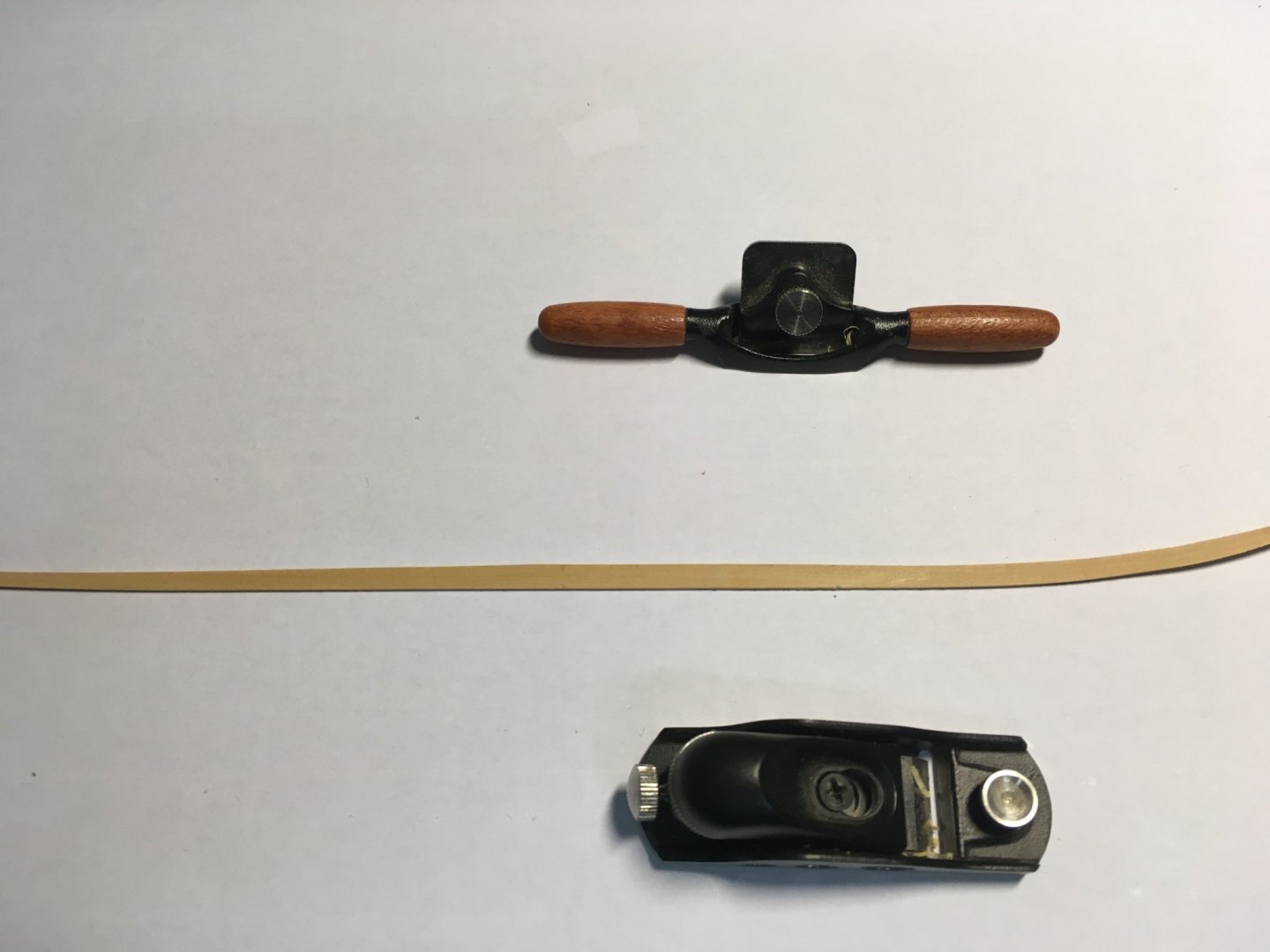
Thanks. Port and starboard final planks finished bar some final bending.
I've found the miniature Veritas tools such as the plane and spokeshave invaluable in shaping these awkward planks.
Christmas will now get in the way of further work for a while. Hopefully I'll find HMS Speedy by Vanguard Models under the Christmas tree, so my main problem in the New Year will be keeping my hands off the new model long enough to finish this one! And I'm feeling a bit guilty that I've not done much to the Winchelsea for a while. Too much to do and too little time - and I'm retired!
Best wishes to everyone for the holidays.
Derek
-
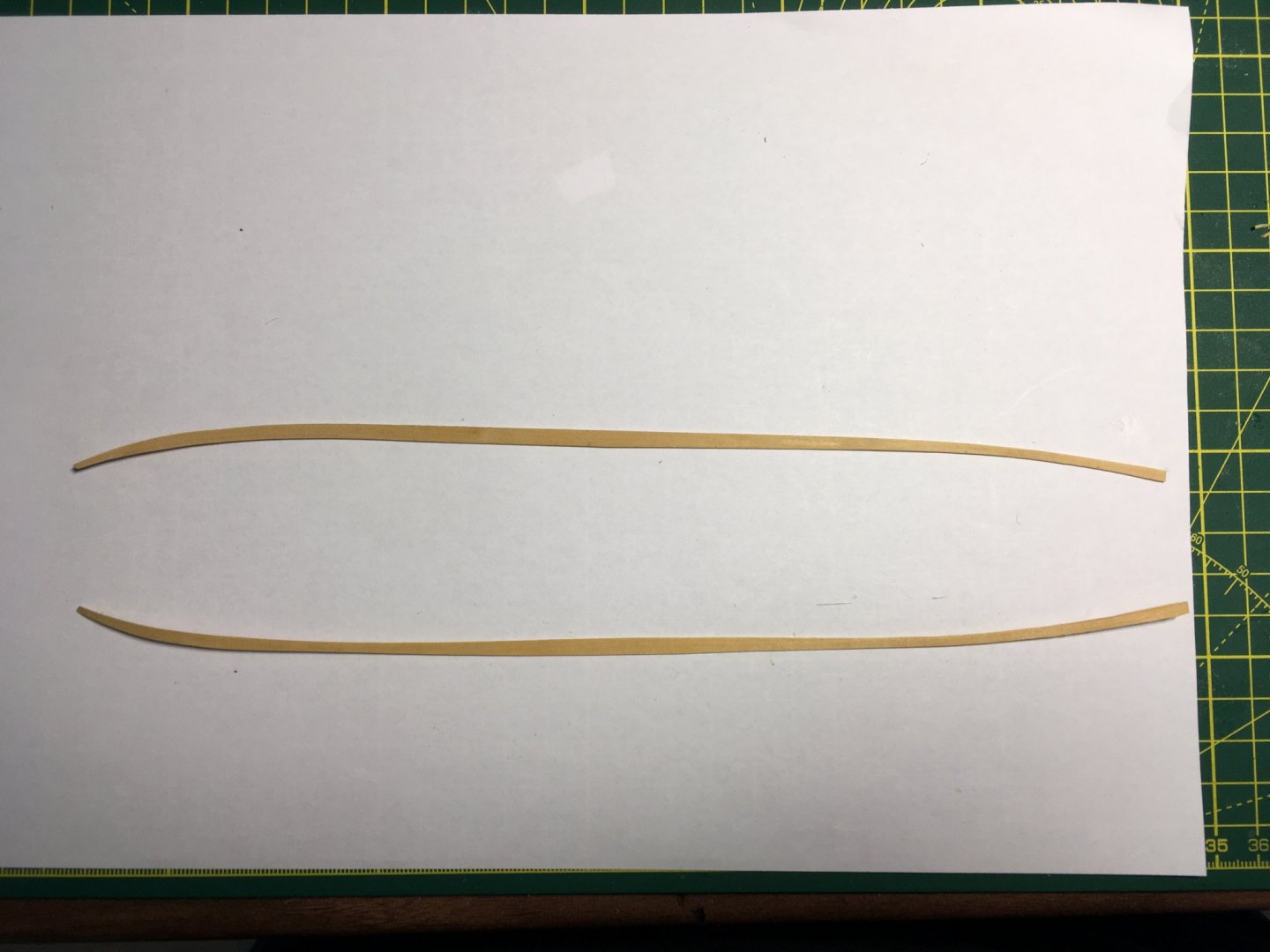
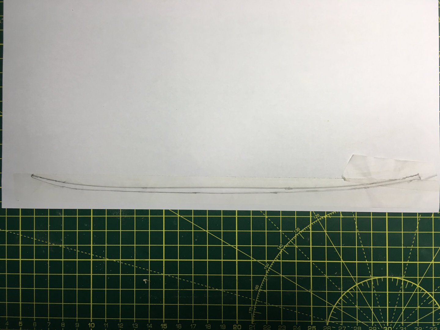
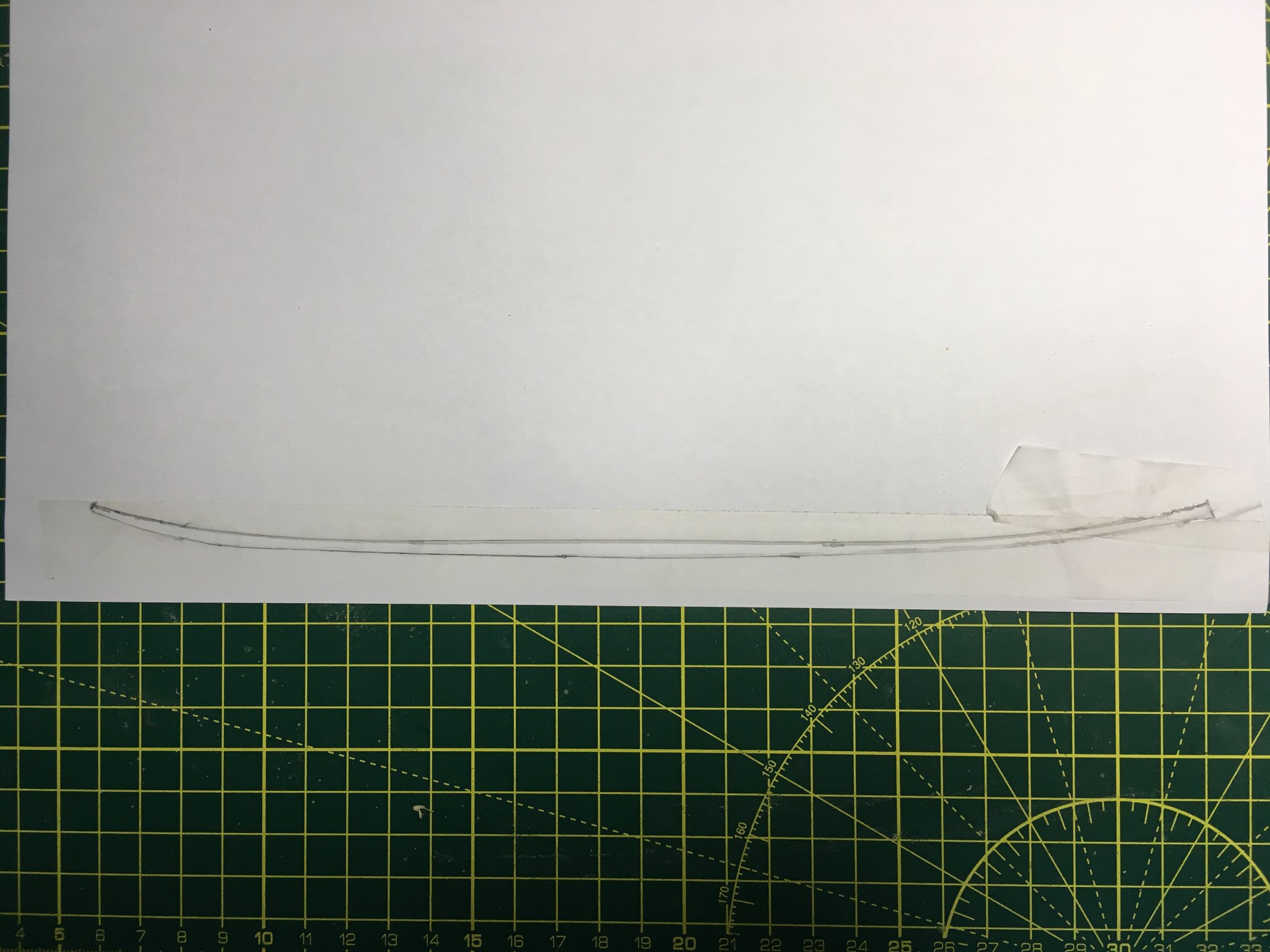
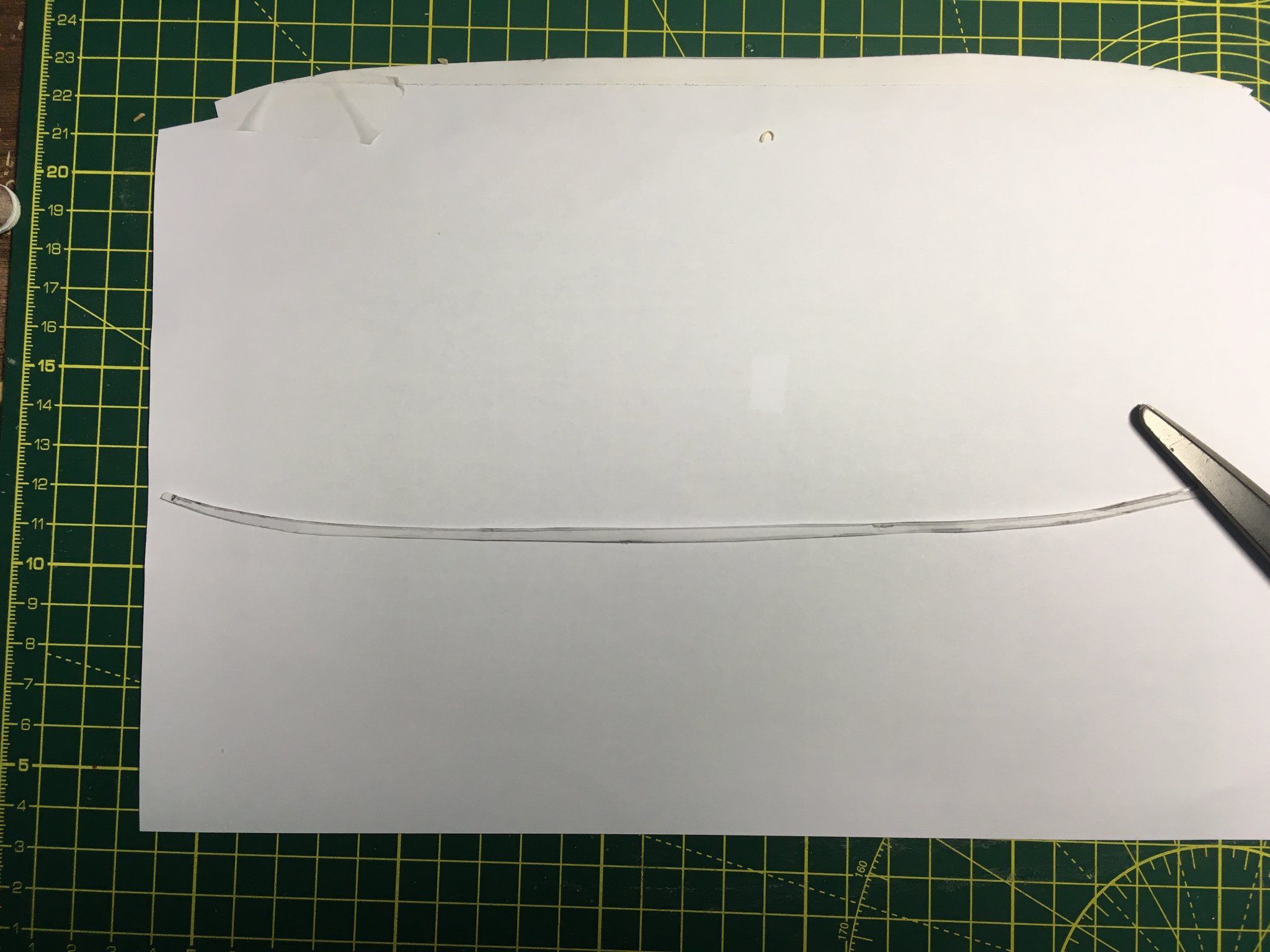
I got distracted by non-ship related business for a few days but managed to get back to the dockyard yesterday afternoon and again this morning for an hour. I've made some progress with the final planks. Starting on the starboard strake, I traced the shape using some low-tack tape. It wasn't wide enough to cover the gap without bending, so I had to use an extra piece of tape at the stern.
I ran the edge of a pencil lead against the top corners of the two planks framing the gap.
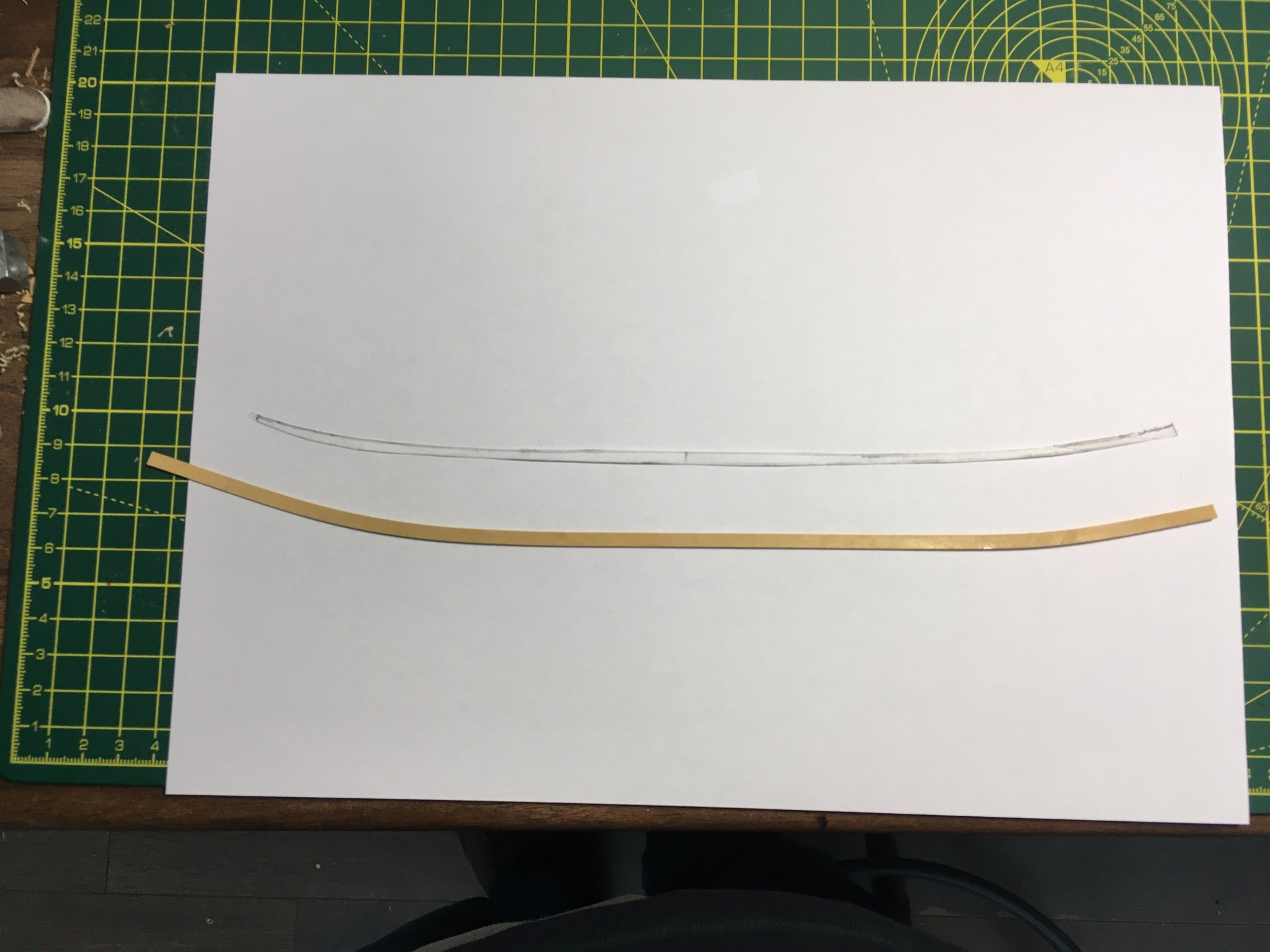
I stuck the tape to a sheet of paper and cut it out. In the photo the pencil line looks very thick. In reality there is a fine black line where the edge of the pencil lead touched the corner of the planks - the smudgy grey line is just where the rest of the lead rubbed against the tape. I was able to follow the thin black line when cutting out the shape.

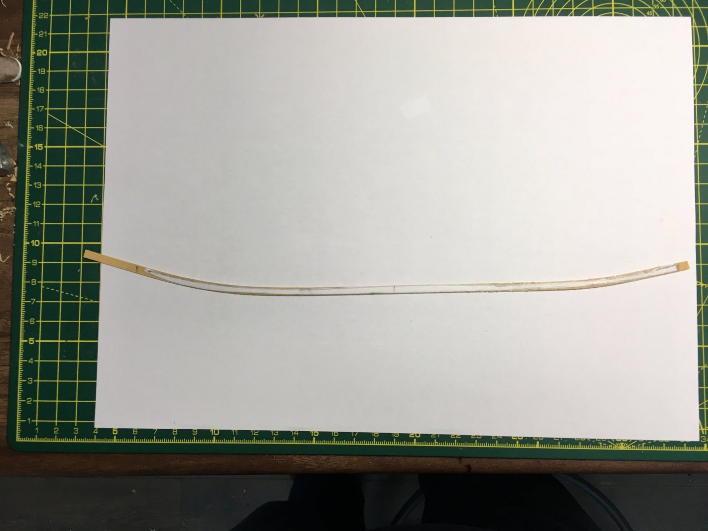
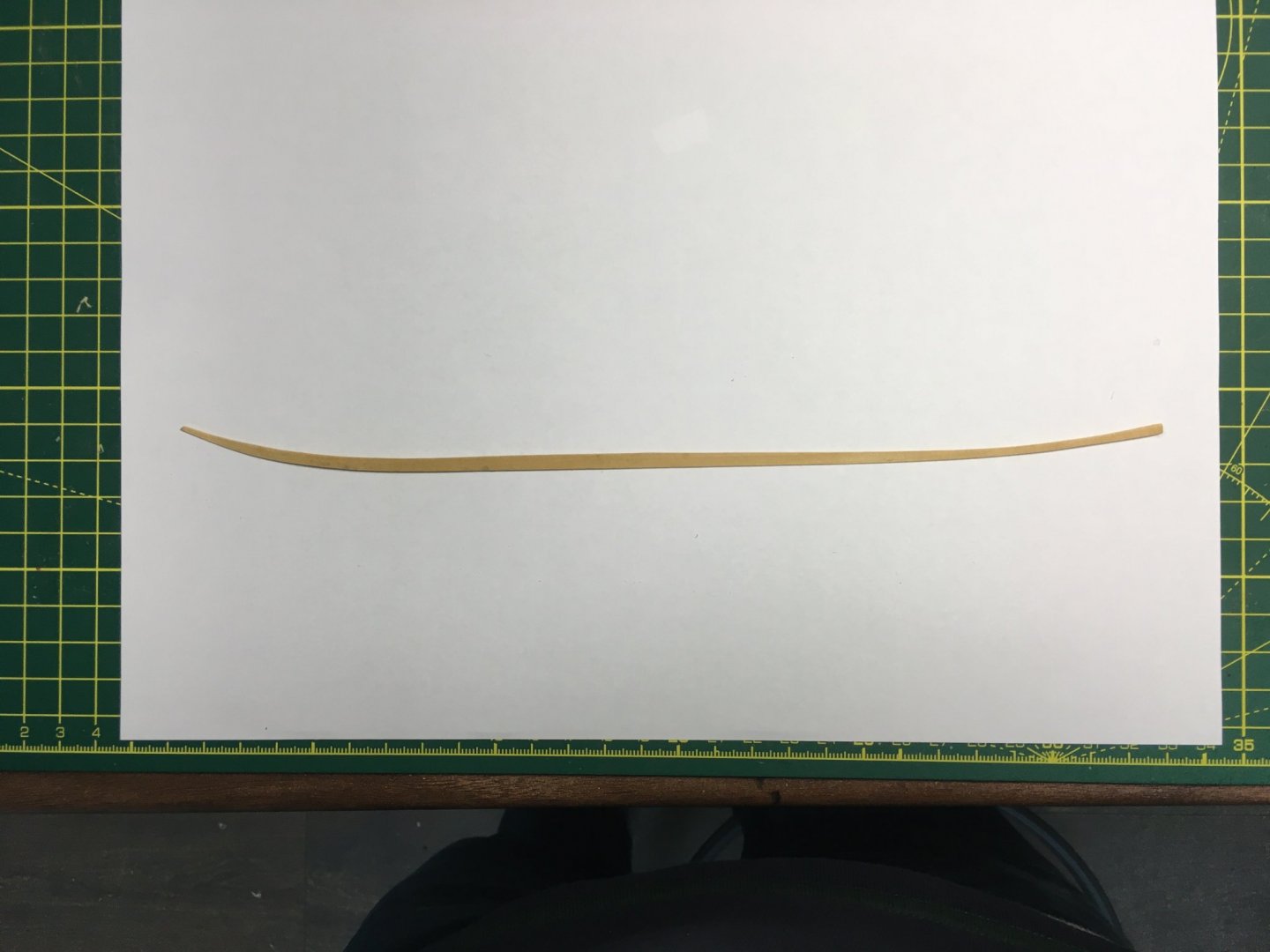
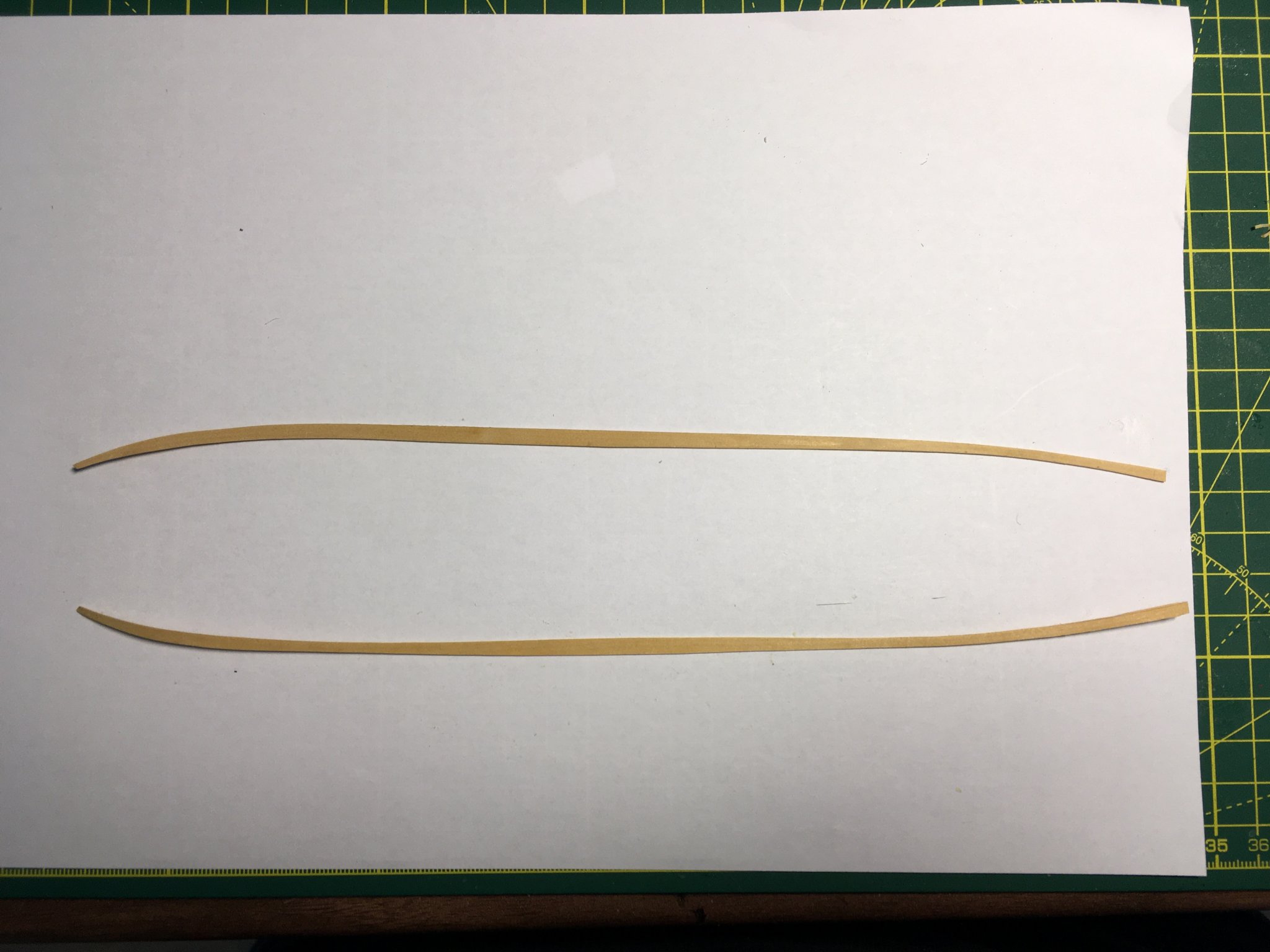
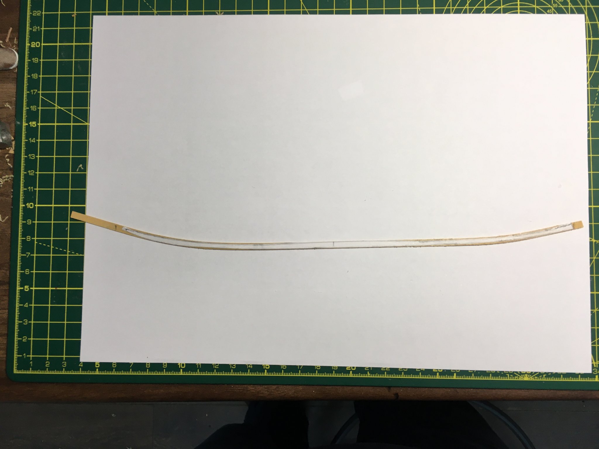
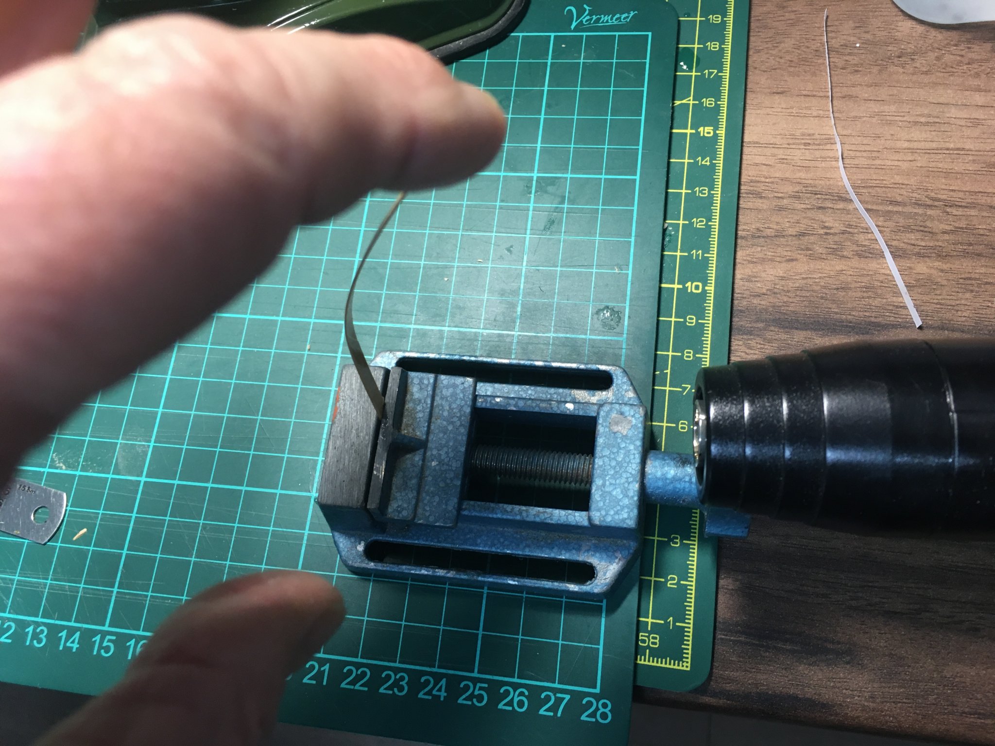
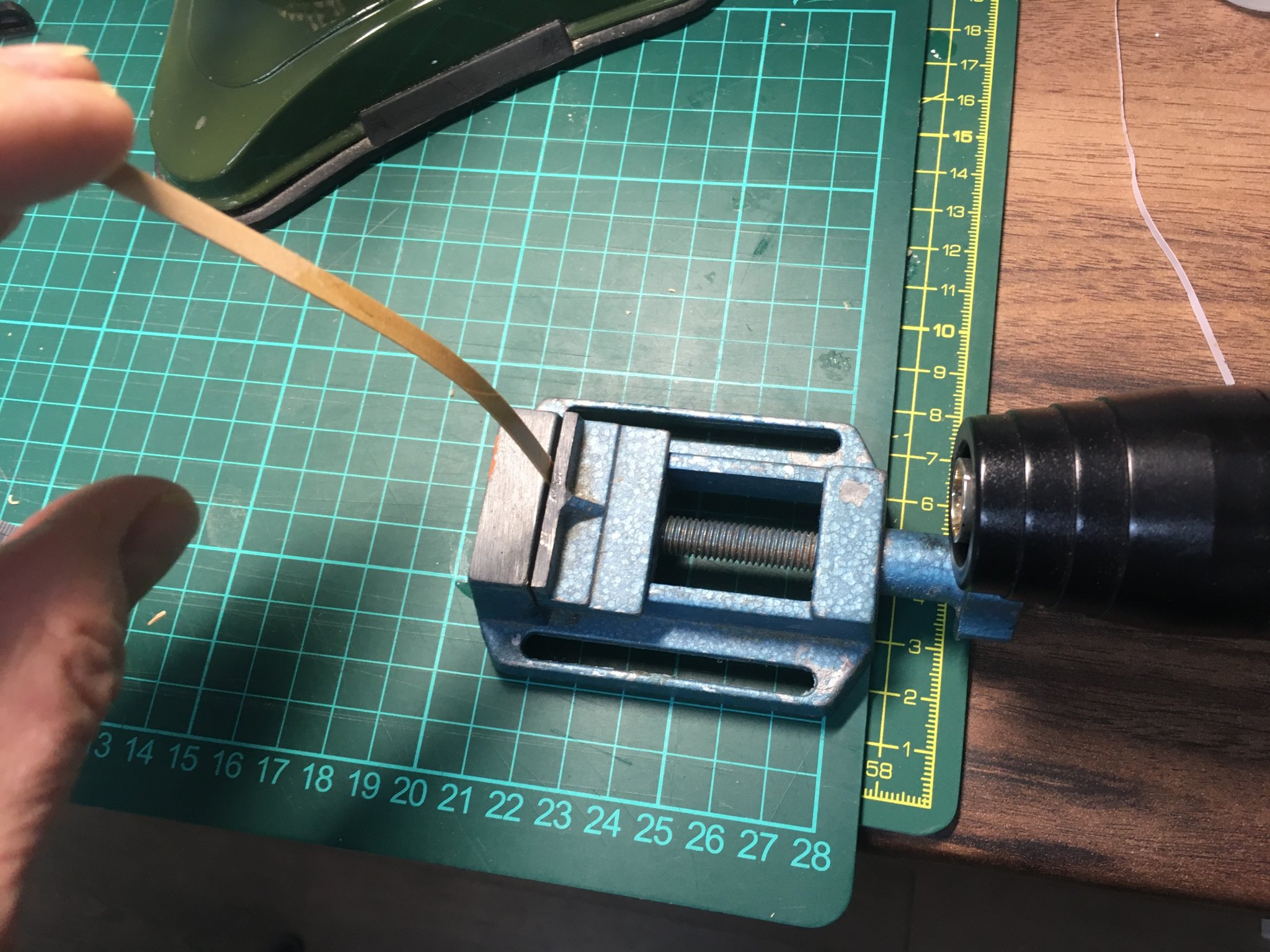
The next job was to bend a boxwood strip to the approximate shape of the template. I used the travel-iron-edge-bending technique. The curves don't need to be exact, so long as the strip covers the template.

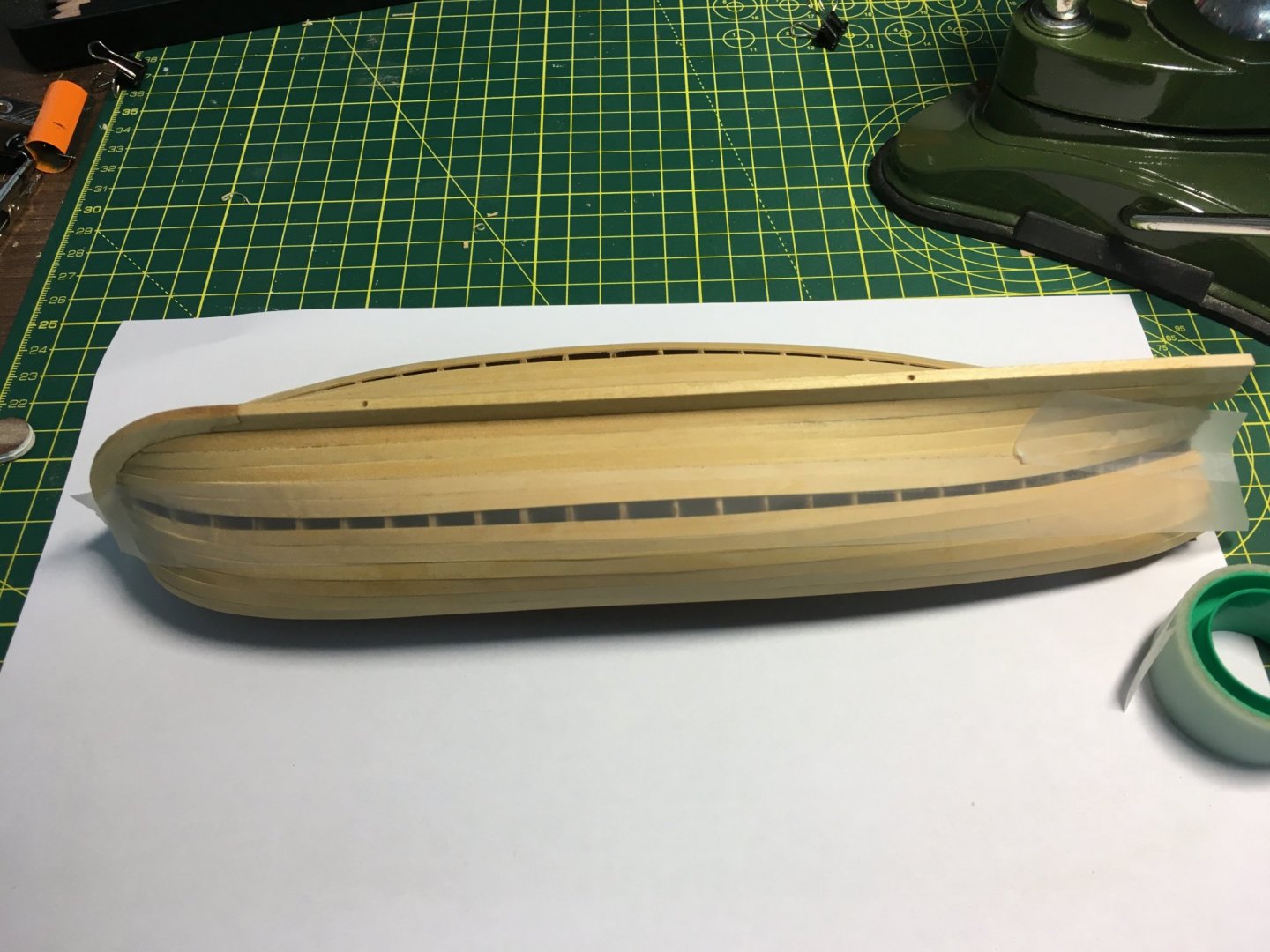
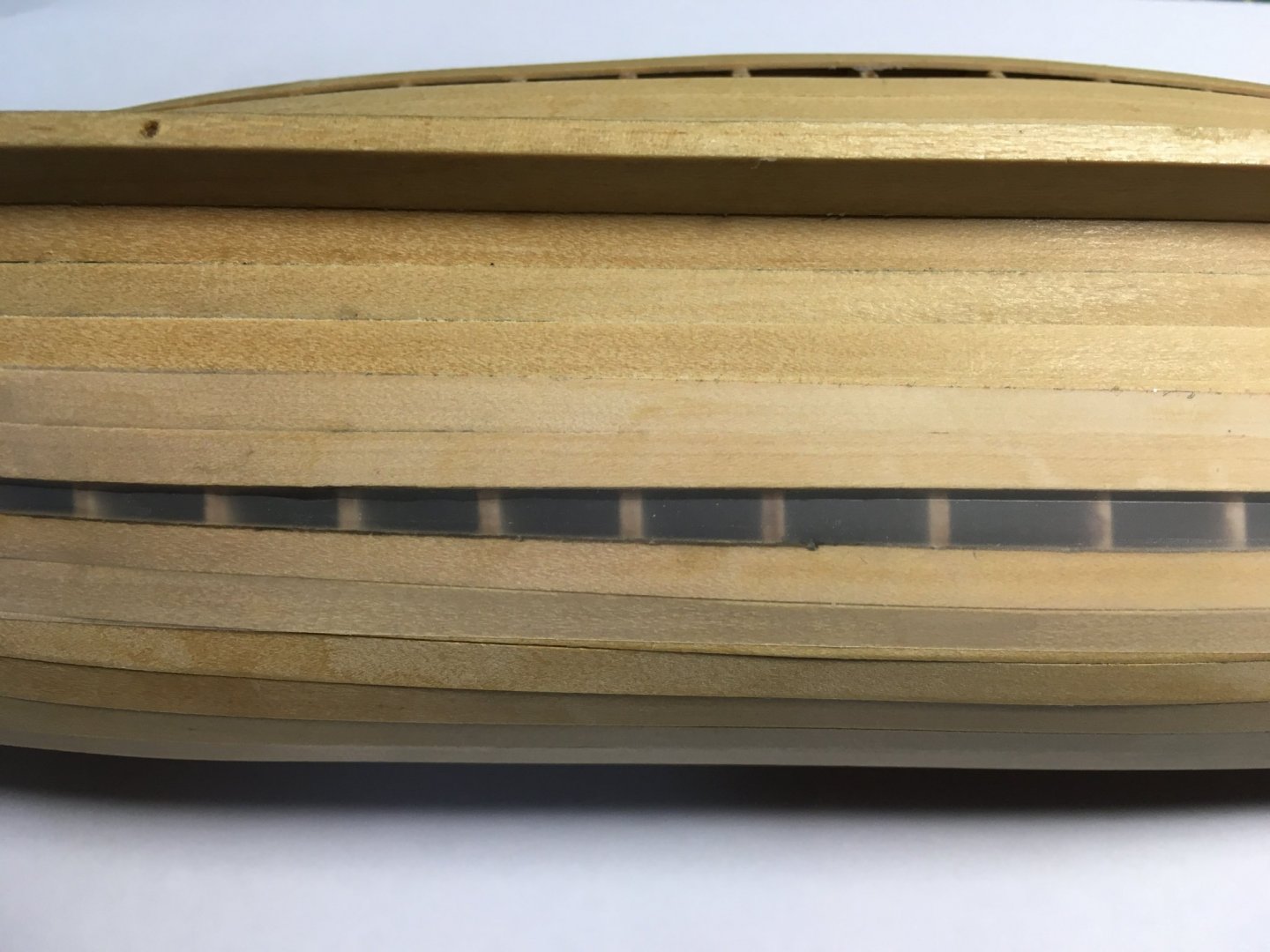
The strip was cut roughly to size, offered up to the gap and final adjustments made with files and sandpaper.
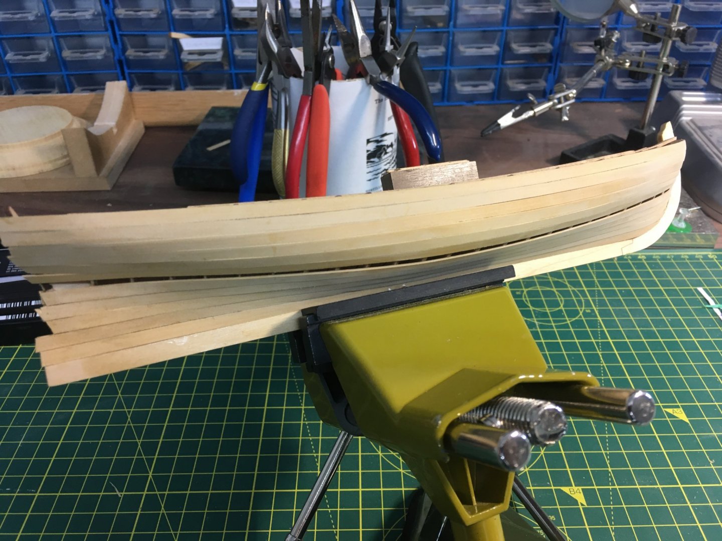
Starboard finished. I must say, although this was a lengthy process I'm happy with the result and glad I made the effort.
Port next.
Derek
-
Nearing the final stretch on the planking - just the last awkward-shaped strake to go. Still looking more uneven and gappy than I'd like - I'm hoping sanding will improve the final appearance. On the positive side, I'm amazed how solid and robust the model has felt since I got the first couple of planks on each side.
Tomorrow I'm going to try tracing the gaps I need to fill. I'll probably try a card template first before transferring the shape to wood. I'm looking forward to the next stages - I've not enjoyed the planking much. However I must say Chuck's edge bending technique seems the way to go, and I suspect it would work even better on hulls with less severe curves to contend with.
Derek
- GrandpaPhil, Edwardkenway, Chuck and 3 others
-
6
-
-
I can't believe how fast you are - it'll take me at least 3 months to get as far as you have, and I'm retired! How much does Chris's innovative design help in that regard? Everything certainly seems to fit together really well.
Keep up the good work. I'm really enjoying your log and can't wait to get my Speedy at Christmas.
Derek
- JpR62, Ryland Craze, Edwardkenway and 1 other
-
4
-
Slow progress on the planking, and gappier than I would like. The problem (apart from my skill level) seems to be the boxwood. Although it's a lovely wood and cuts beautifully, it is harder than woods such as basswood and correspondingly harder to bend and shape.
I'll persevere.
Derek
- bruce d, MEDDO, Ryland Craze and 3 others
-
6
-
On with the planking. Slowly!
I've got the garboard strakes on both sides.

I've taken this strake a lot further forward than in Chuck's instructions - I just didn't like the way the next strake above the garboard had to be bent to get it to sit alongside. I tried it with some test planks and I just couldn't get it right. So I decided to avoid this by keeping the top edge of the garboard as straight as possible into the bows. I realise this means the remaining planks will need to be narrower in the bow area as there will be less space for them, but I've measured the gap and the tapering will not be too severe.
Looking at the picture above, I can see that the first two planks I fitted on the starboard side don't fit together as well as I might wish. I hope they'll look better after sanding, and after the decorative frieze is fitted. Either way, I'll be looking to improve my techniques as I tackle the more visible strakes.
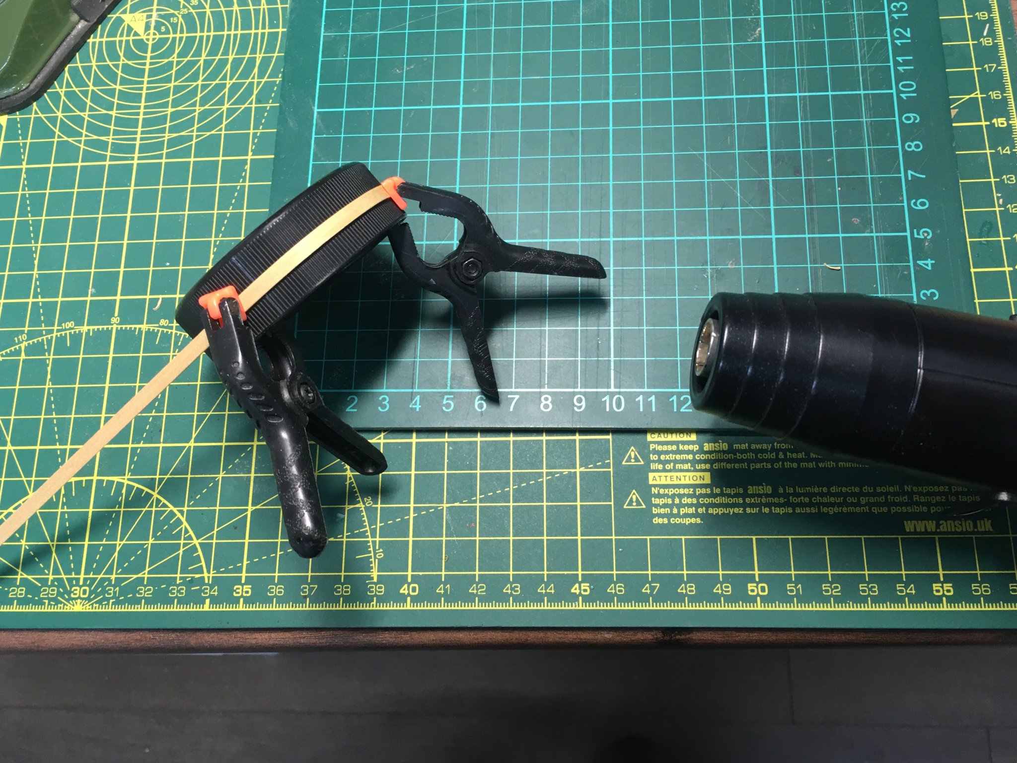
On that point, I've stopped using my Amati plank bender (the one that looks like a converted soldering iron). I find I get better results wetting planks, clamping them to suitable curved items and drying them with a hot air gun.

I 'borrowed' the hot air gun from my wife, who uses it in her card making hobby. It has two settings - the cooler one is ideal for the shrink wrap tube I use to simulate iron bands on, for example, anchor stocks and masts; the hotter works well for plank bending. The boxwood I'm using seems totally unfazed by the treatment. None of the raised grain wetting usually causes.
I'm sure her hair dryer would work equally well, but borrowing that would push my luck too far!
Derek
- Ryland Craze, Edwardkenway, JpR62 and 4 others
-
7
-
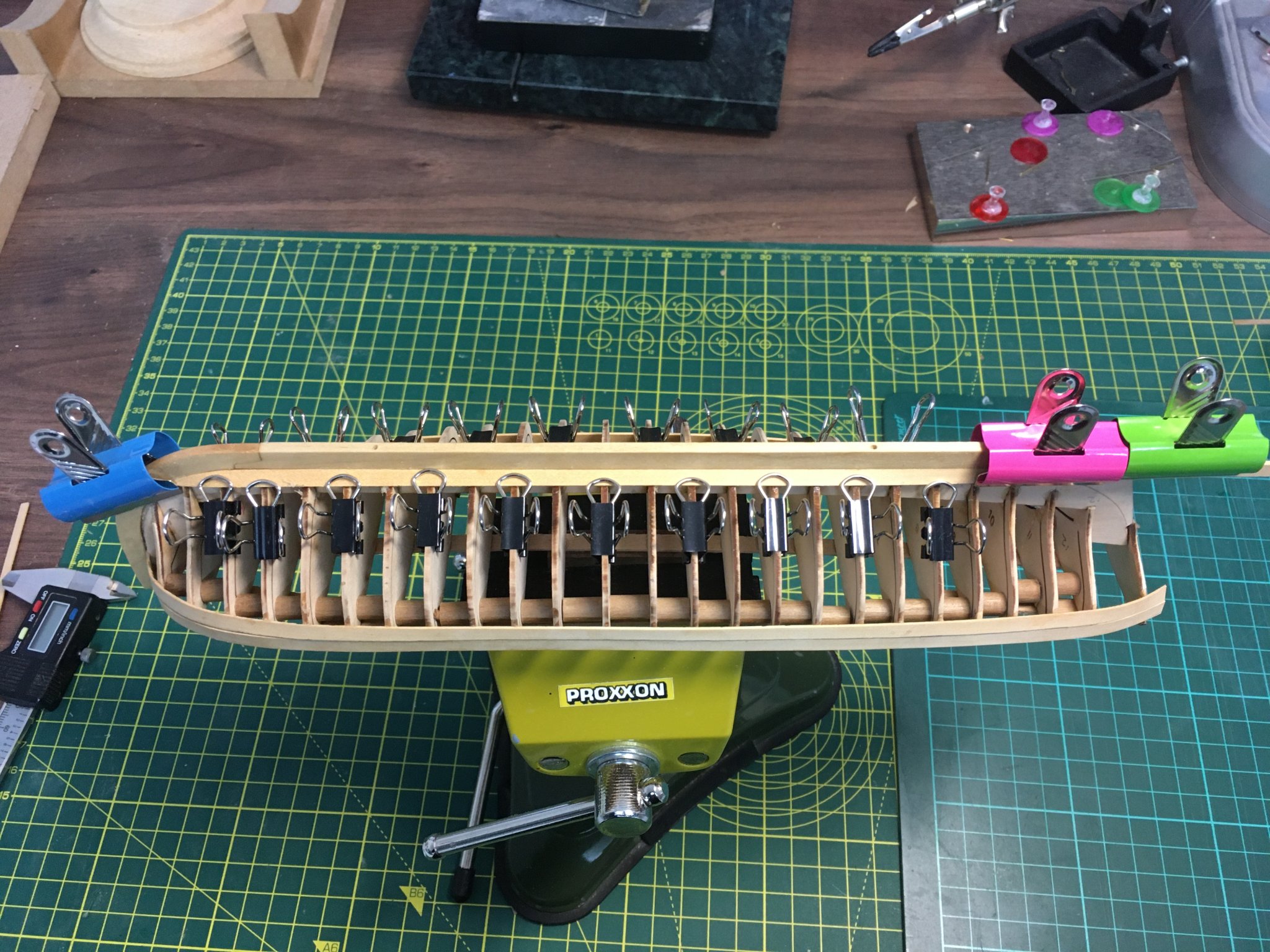
Got the first two strakes in, in between garden chores.
Helps to show off the lovely lines of the pinnace. Back to the garden.
Derek
-
Thanks OC.
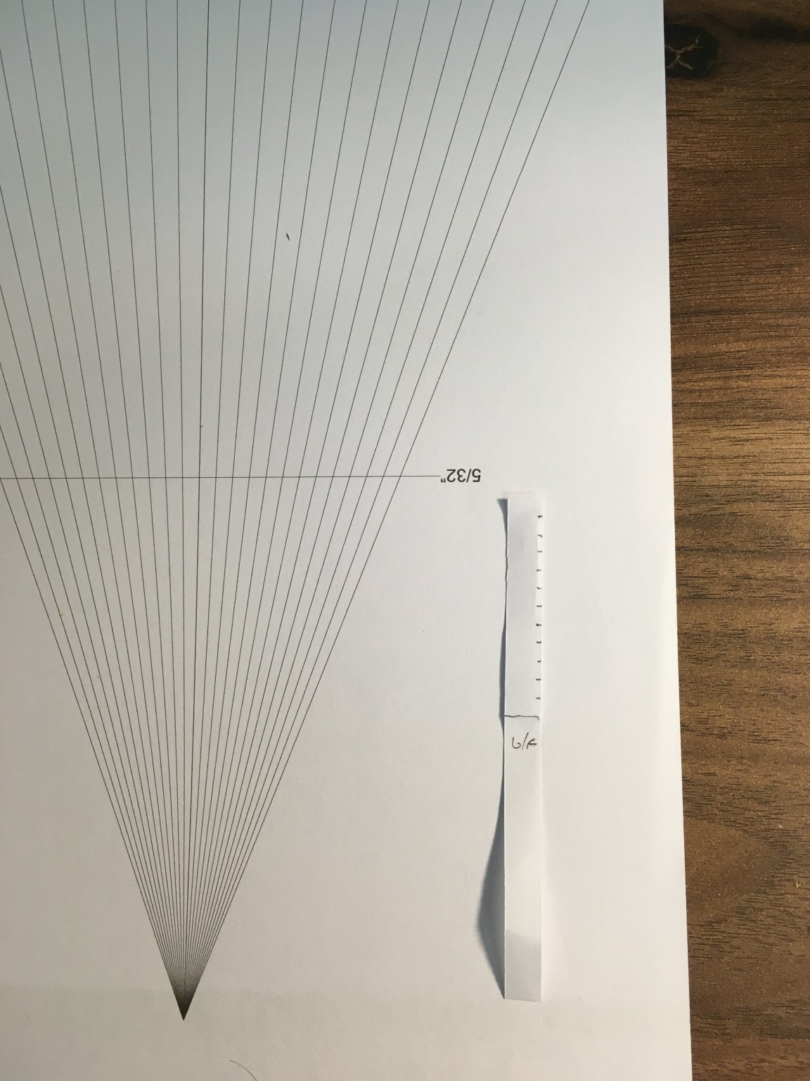
Not much progress over the last few days - more time spent in the garden preparing for Winter than in the dockyard. I tried marking the frames but with mixed success. I'm sure I understand the principle, and I printed off a fan and prepared tick strips as per instructions:

I don't know if it is because the frames are very narrow or I'm too cack-handed, but I found it very difficult to hold the tick strip against the frame edge and mark it. I just couldn't mark the frames accurately enough. For example, if I marked two frames that I knew were the same size (when measured from the rabbet to the sheer), the marks didn't line up exactly. In the end I decided that, because the frames were all of a very similar dimension apart from the last 3 or 4 from the bow and stern, I could safely fit the first couple of strakes on each side, and possibly the garboard strakes, then have another go at marking off the remaining gaps.
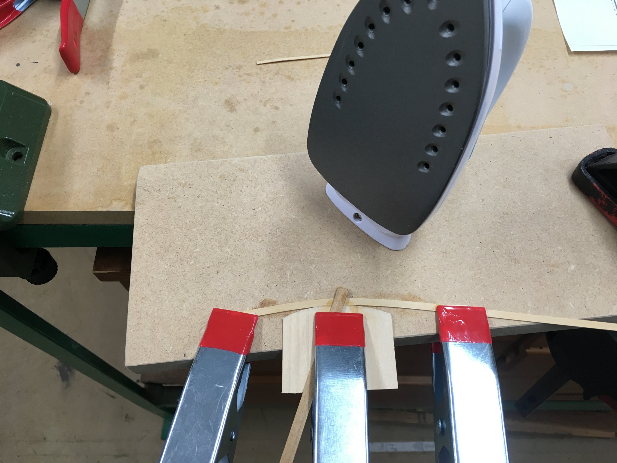
Taking another tip from Chuck Passaro, I got hold of a cheap travel iron to help with edge bending - works a treat!

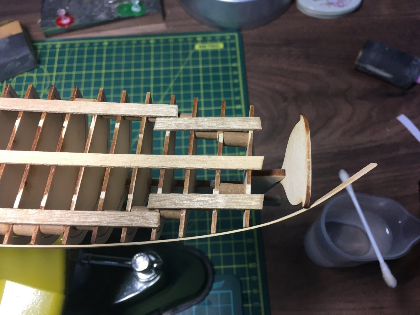
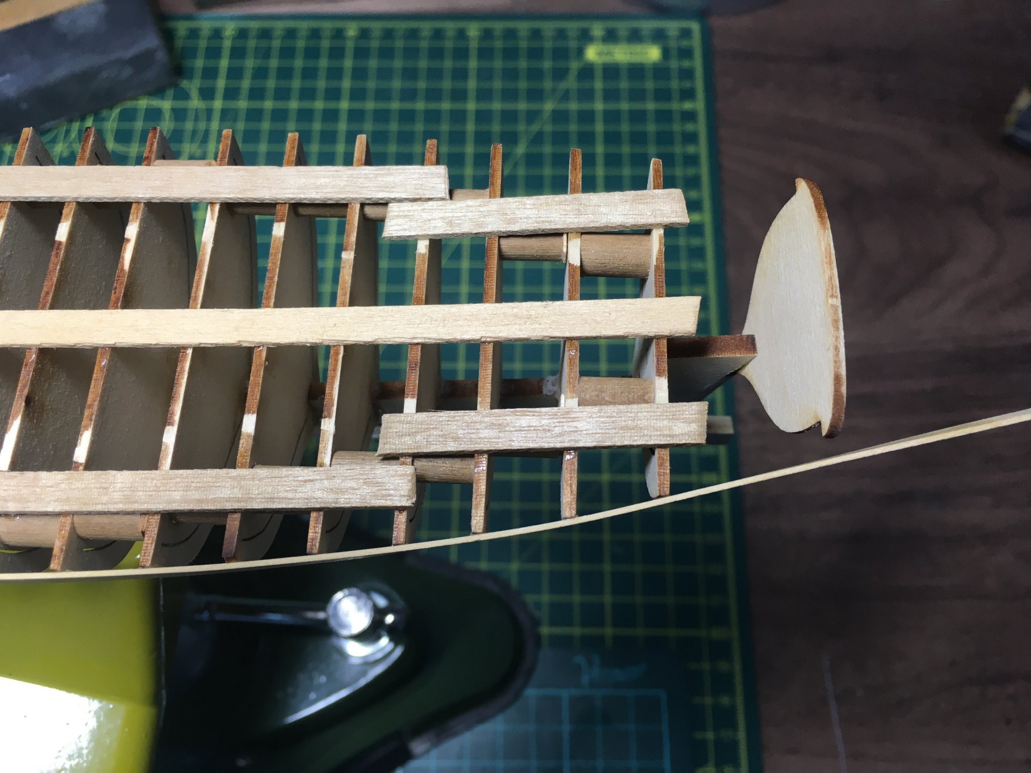
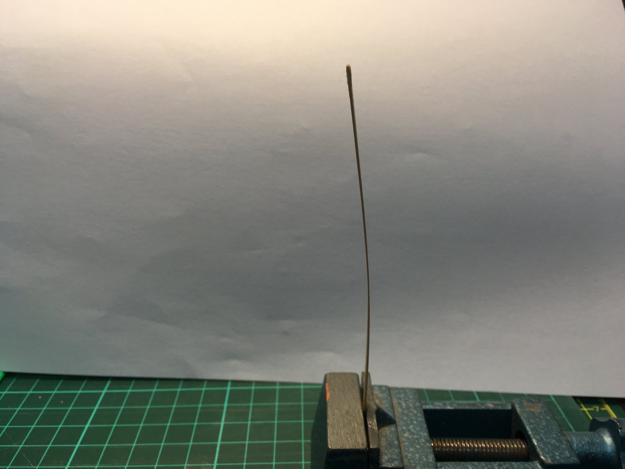
To bend strips in the flat dimension I clamped them to a variety of curved surfaces and used a hot air blower to set the shape. I got the first strake on but clearly hadn't curved it enough at the stern:

I wanted to see if I could increase the curve by heating the plank in situ, but wasn't sure which side of the wood it would be best to apply the water and heat to. So I did a couple of quick tests with a scrap piece of strip on the bench.


It didn't seem to matter which side I went, the curve stayed in either way.
I ended up hedging my bets and applying water and hot air to both sides whilst holding the strip tight against the transom. When released there was a marked improvement which should glue up much better.
Meanwhile, back to the garden and my new favourite tool (next to my Byres saw that is) - a petrol shredder that takes branches up to 4".

- GrandpaPhil, paulsutcliffe, JpR62 and 6 others
-
9
-
-
Master Shipwright version ordered - can't wait ('though I'll have to - my wife insists I can't even look at it until Christmas)!
Derek
- Edwardkenway, Canute, VTHokiEE and 3 others
-
6


HMS Speedy by Vane - Vanguard Models - Scale 1:64 - Master Shipwright (limited edition)
in - Kit build logs for subjects built from 1751 - 1800
Posted
Thanks Bob. I suspect we’re at cross purposes - my fault for mentioning edge bending. You’re right when you say the gun port patterns don’t require lateral bending. What I struggled with was bending the pattern across it’s width to follow the tumblehome. This was quite pronounced near the bows. Rather than hijack Vane’s I’ll cover my experience in my own log.
Derek