HOLIDAY DONATION DRIVE - SUPPORT MSW - DO YOUR PART TO KEEP THIS GREAT FORUM GOING! (Only 24 donations so far out of 49,000 members - C'mon guys!)
×

md1400cs
-
Posts
2,839 -
Joined
-
Last visited
Content Type
Profiles
Forums
Gallery
Events
Everything posted by md1400cs
-
 Mates, thanks for all likes and/or just dropping by for a look. ==================== Joe, As usual a big thanks for following along and posting such encouraging comments. -E.J. Thanks as well. Also really enjoying following your build log –cheers Frank, (Riverboat) Plan B was a “winner” indeed. OH you have started a new boat. I will look for your build log (Chinese Junks always had a place of admiration for me) Do you plan on “aging” it as you did with your awesome Alert? Martyn (BV.) thanks as well. Happy to have been of help with your PM regarding the cannons J Patrick - Thanks your Google English is great - ha ha Dave, happy that you are feeling at home with my “clamp” funny , but it did not work grrrr (J Frank, thanks as well. Yes summer is going well indeed. Enjoy your fishing season over there on the East Coast. Off to Michael’s looking for some decorative bits, need to add some work to the galleries as I had mentioned above.
 -
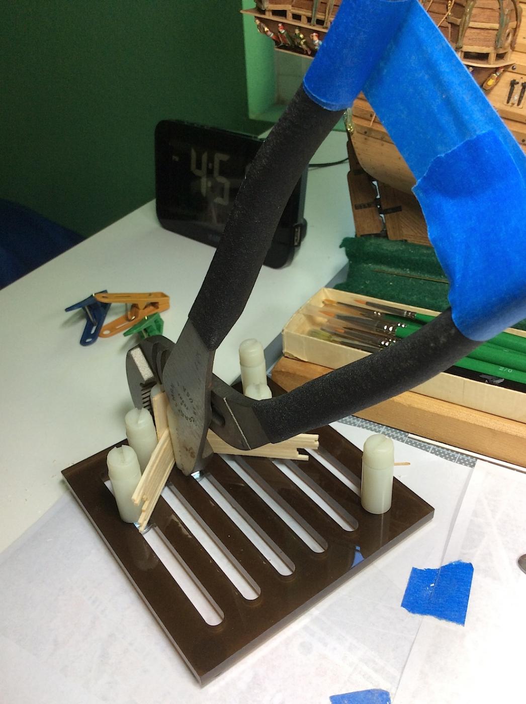
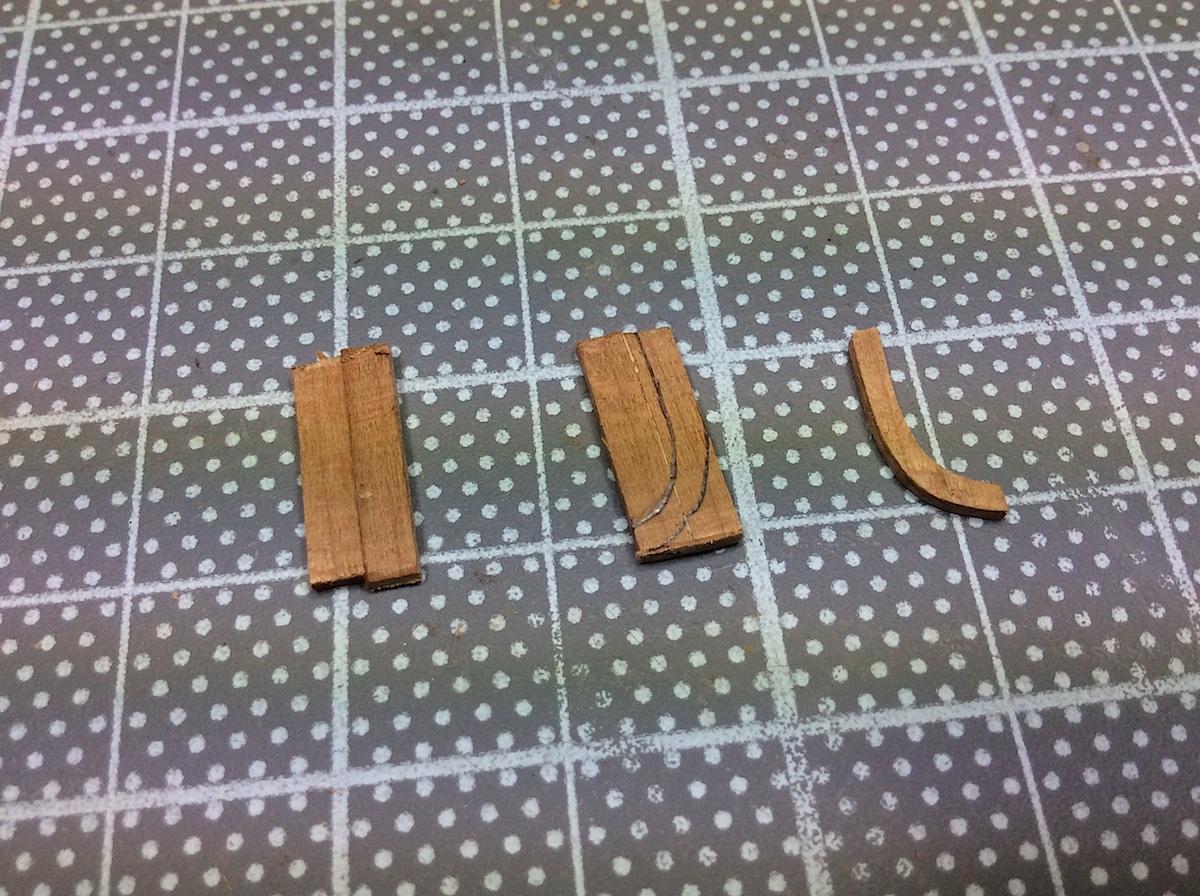
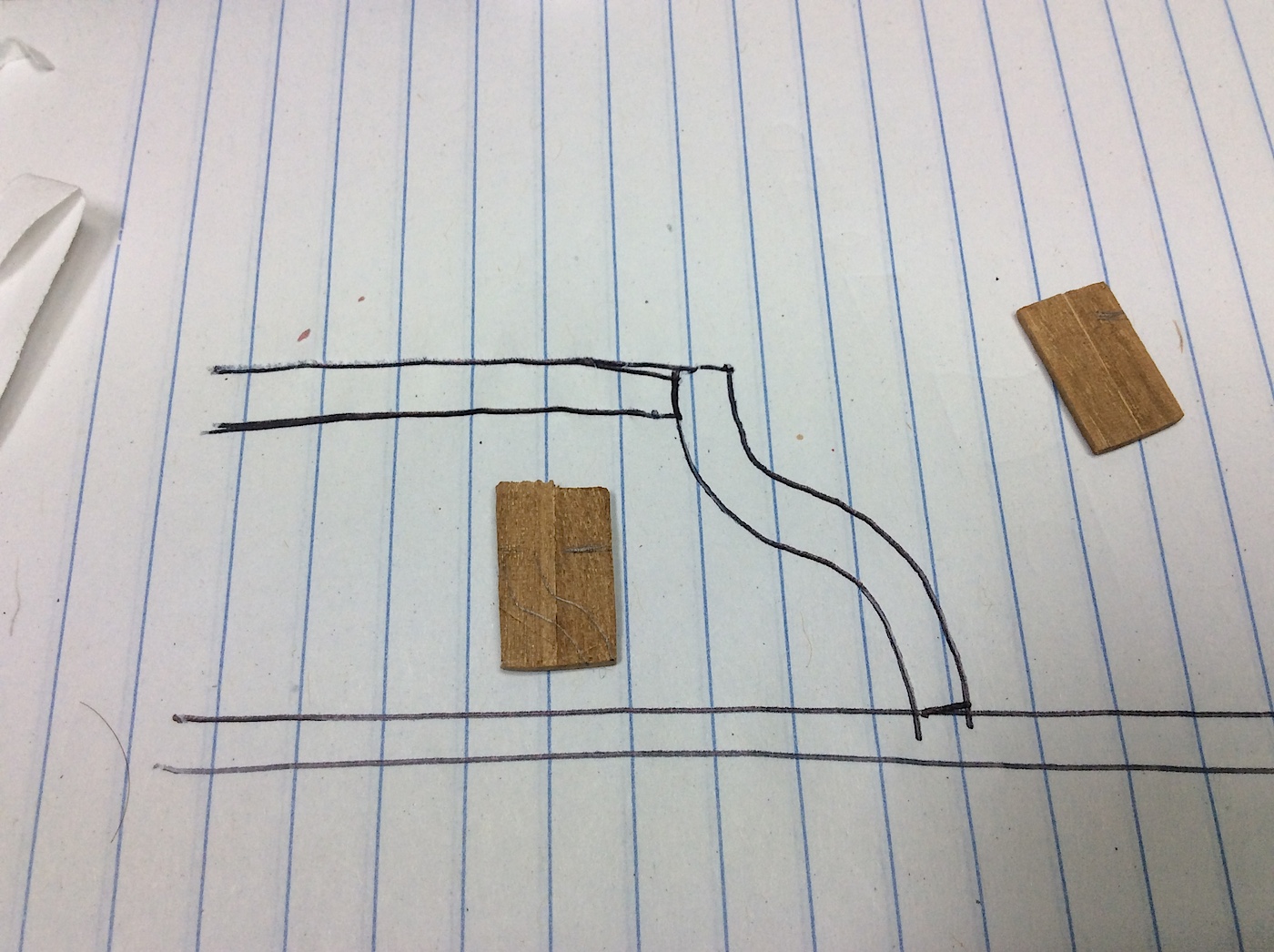
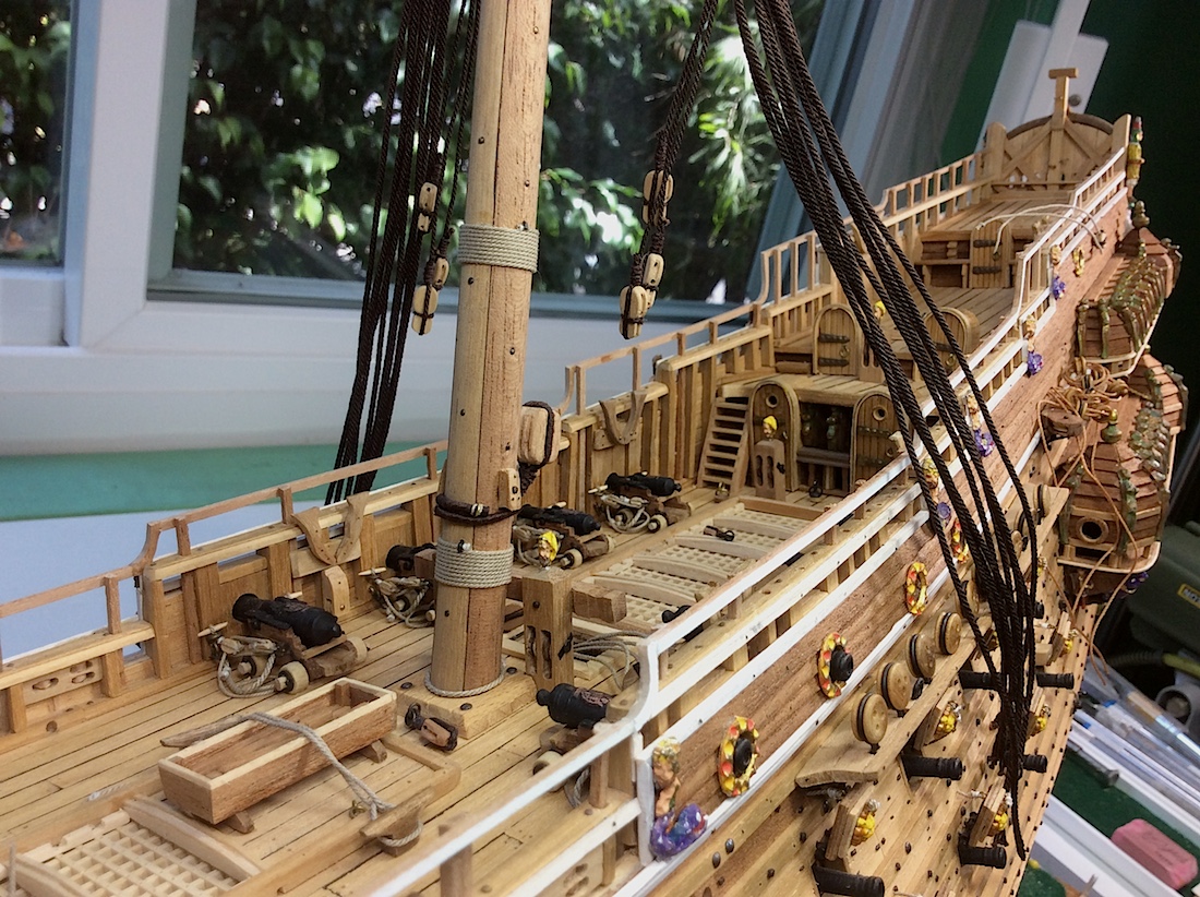
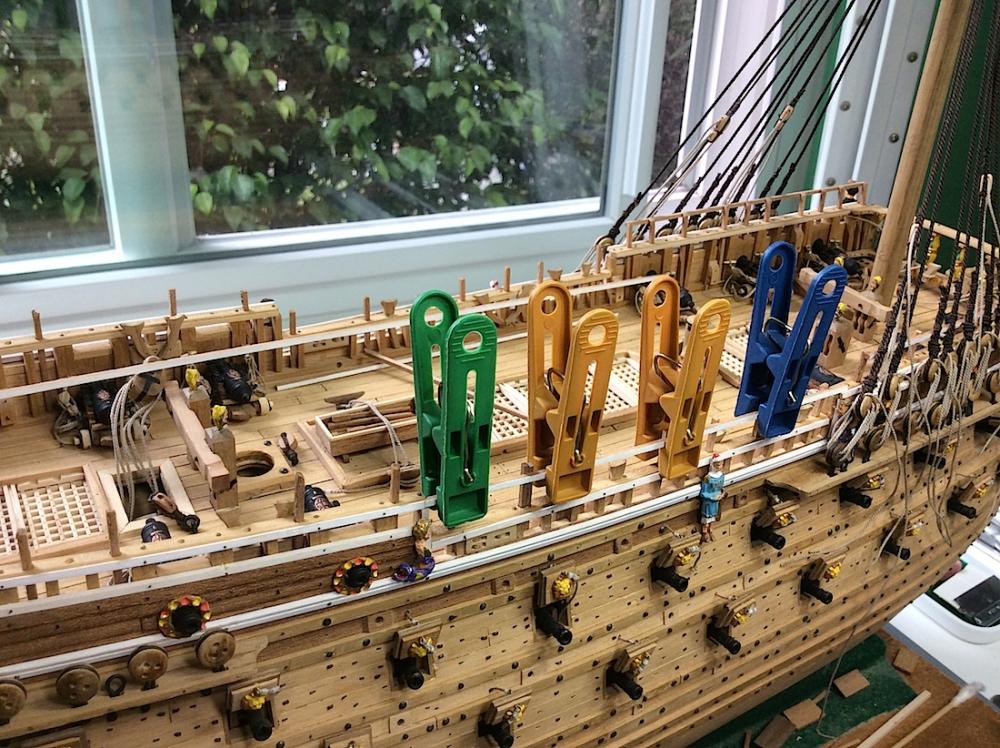
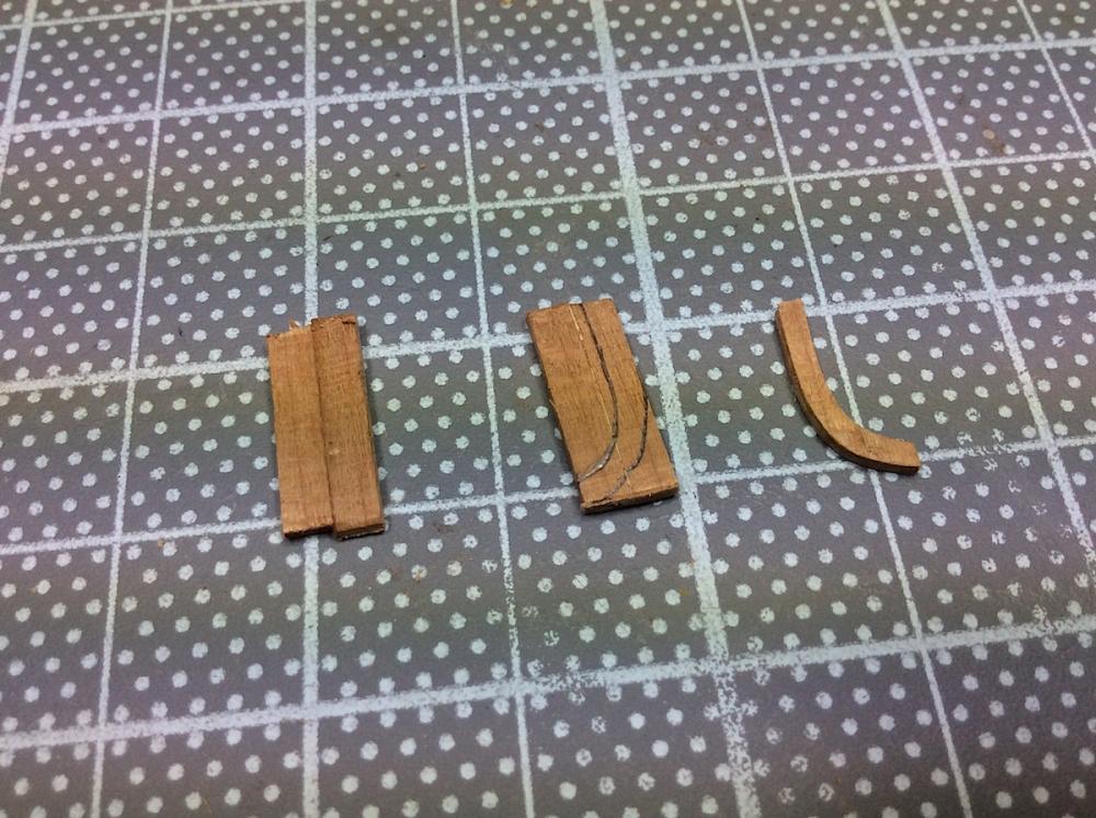
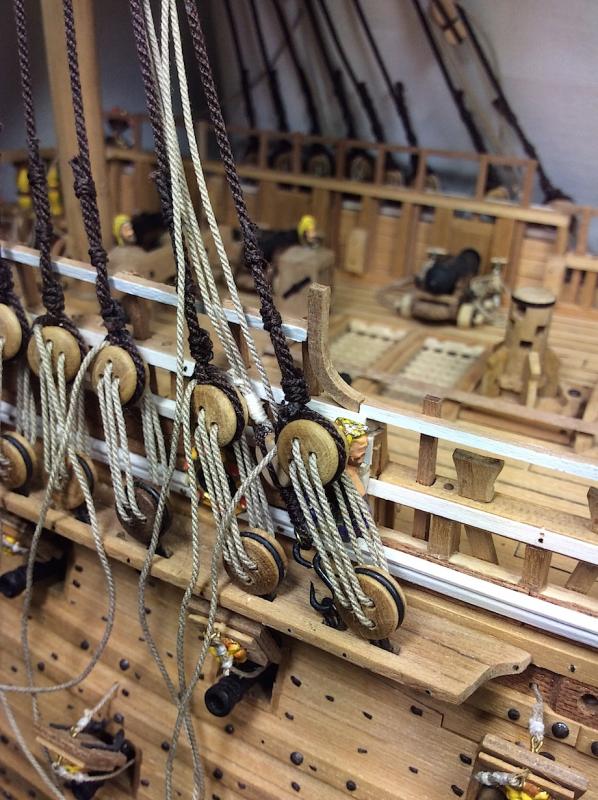
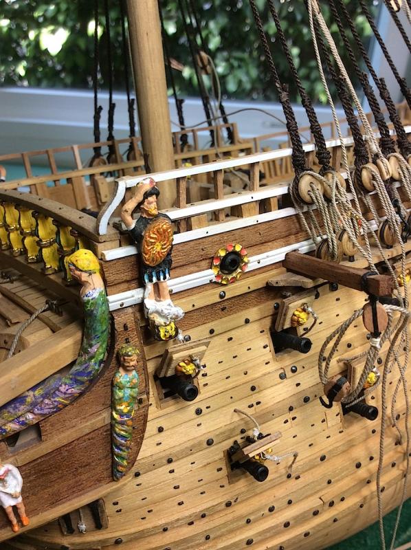
Hi Mates, Finished installing the upper railings. As I mentioned in a previous post I had my “issues” installing the horizontal rails on each side of the foremast after installing the shrouds. So that done, as well as some tidying up of the carriage ropes I can move forward and attach the mainmast, and its lower shrouds. Now needed to make the bent 90º planks to link the horizontal bits. Well that had its issues as well. Hmmm. I must have tried to bend 50 pieces (needed 10) All but one plank allowed itself to be bent 90º. Even tried soft wood to no avail. I believe it was my lack of skills, and the extreme bend that was needed? So plan B. Last pic I will be pulling out those badly made pulley/blocks now that I have, and know how to (more or less) use my Proxxon MF70 J Before “moving forward” I plan to revisit the galleries and add some details. This is certainly one of the most difficult areas of this ship to articulate correctly especially with the Corel kit as a base. Not complaining – this has been widely discussed here at MSW with those of us building this ship. I had some left over bits from the upper railings that will work very well. Cheers


-
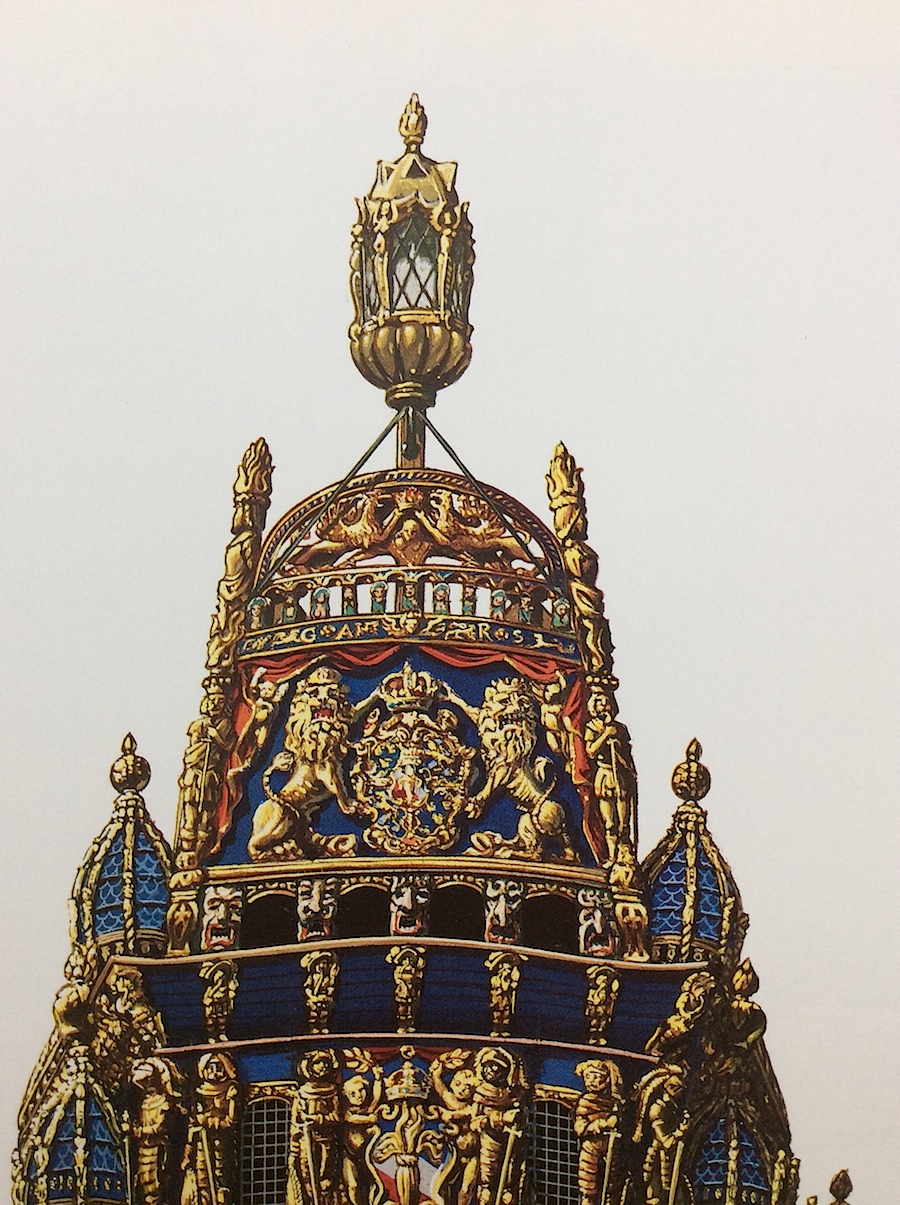
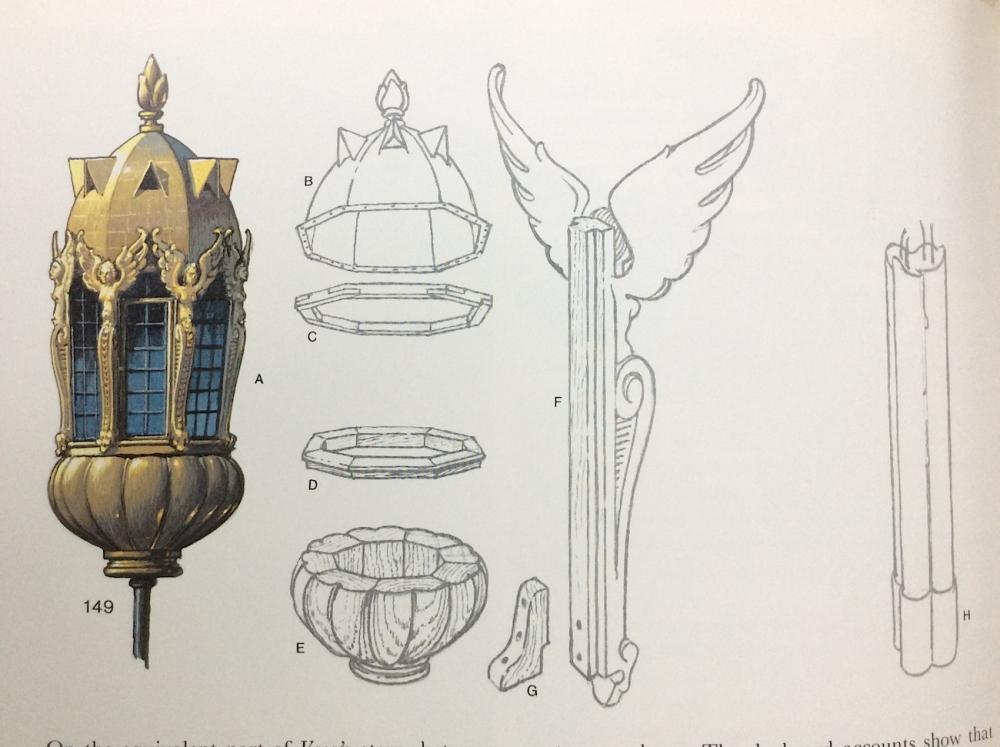
Patrick, Nice work indeed. Lantern is a mystery in terms of how it looked. Salvage did not locate the original. Here are some poss. examples. first two pics are from Landström's book. Thought Fred Hoecker does not think that the angels were included. pic. 3 may be actually more representative. Hope this helps PS: I will build mine looking like the book's without the angels (just as well I can't carve (:-( ) Cheers,

- 63 replies
-
- 8
-

-
- vasa
- billing boats
- (and 1 more)
-
Mark, Beautiful work indeed. Clever find much nicer now. PS: I've also been seen at Michael's and Jo-Ann's aimlessly searching for bits of this-that-and-the-other - ha ha I did buy two types of cloth at Jo-Anns assuming I build up my confidence for sails. Will you fully rig this one as well?
- 652 replies
-
- 2
-
-
- royal william
- euromodel
- (and 1 more)
-
Gaetan, Simply brilliant. Just found your log and will be following. PS: that is QUITE a shipyard that you have there (:-)
- 728 replies
-
- 2
-
-
- le fleuron
- 64 gun
- (and 1 more)
-
Mark, Yes as Jason, and others have said - super nice. You may have to fly the queen over and have her Royalty crack a bottle of bubbly on the bow when finished. I think that she was alive when it was originally launched. Cheers !!
- 652 replies
-
- 1
-
-
- royal william
- euromodel
- (and 1 more)
-
MONTAÑES by Amalio
md1400cs replied to Amalio's topic in - Build logs for subjects built 1751 - 1800
Amalio, Superb work indeed. For many of us (I believe) that your inner mold would be our finished outer hulls that we would also be proud of (;-) I will follow with much interest. -
Great, My wife always buys "artistic" toothpics. I always keep those in mind ha ha - Nice details!
- 652 replies
-
- 1
-
-
- royal william
- euromodel
- (and 1 more)
-
Mark, As I've mentioned before (I think) - your level of research for this build is superlative. Learning a lot just following along as a sophomore - well almost a junior I hope (:-)))
-
Buck, Thanks indeed. You have more confidence in me than I have of myself, but your kind words have been taken to heart. The stern section of the SOS, for example is NOT for the faint of heart (:-) It is such an amazingly beautiful ship that needs, deep attention to details to make it look "right". The carvings alone are in-and-of-themselves works of art. Not sure that any of the kits available have proper castings? hmmm Cheers, and thanks for your kind post.
-
Martyn, Corel has some issues, but it is a very good kit nonetheless. If you are interested, much earlier in my log I tore out and rebuilt sections that were totally inaccurate. You may want to gloss through some of those postings. Had I known (well been more knowledgeable) after just starting, I could have avoided and easily built around the glaring Corel errors. (:-) I appreciate your interest in following my log, I hope that some "fix" areas will prove valuable for you. If you like, you are also welcome to PM me at any time. PS: Billings Vasa instructions can be downloaded in pdf files here: https://drive.google.com/folderview?id=0Bw40frlcNqbjOTNlYTE5Y2YtMGUyNC00NGE0LWE0ZTktNTRmZjFhNmM0MjM4&usp=drive_web&ddrp=1&hl=en# Second row last on right third row first on left. Excellent back up build information. And same scale. PS 2: SOS is my dream build - not there yet in terms of skills, but getting much closer (comfort-skills wise) Sincerely,
-
Mark, Just catching up. Excellent - a treat for the eyes.
- 652 replies
-
- 1
-
-
- royal william
- euromodel
- (and 1 more)
-
Mr. P, Excellent, I will also look forward to following along. The metal work looks indeed to be super detailed. Nice!. I understand your frustration in having to wait for updates. BUT you are right, it gives you the time window not to rush, and allowing you to really work on details. in between. Actually a positive. Regards,
-
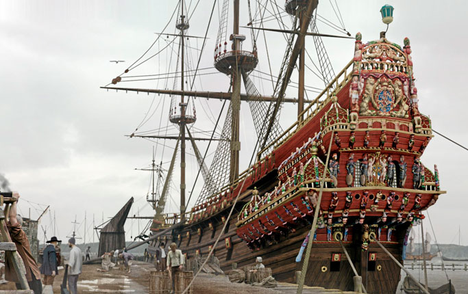
Bill, Thanks indeed. Rick, not to worry. It seems that "accurate" changes to Vasa's rigging are continuously surfacing. It might be, that six months from now that they will go back to suggesting that the pin rails were in fact "ok" Swedish ships in the early 1600s, it seems/I've learned, had not recorded rigging plans from that period - so it has become a partial guessing game for some details. BV, Which Vasa kit have you ordered?. You will find great build logs here for Corel and Billings - (along with a new product that just came out - DeAgostini 1/65th month by month subscription) A new log has just been posted here a MSW - that kit looks to be awesome - hmmmm....but BIG ha ha good luck (:-) enjoy. The wonderful aspect of this ship are the hundreds of photographs that are available. Really an amazing reality look into the 16th century. Cheers,
-
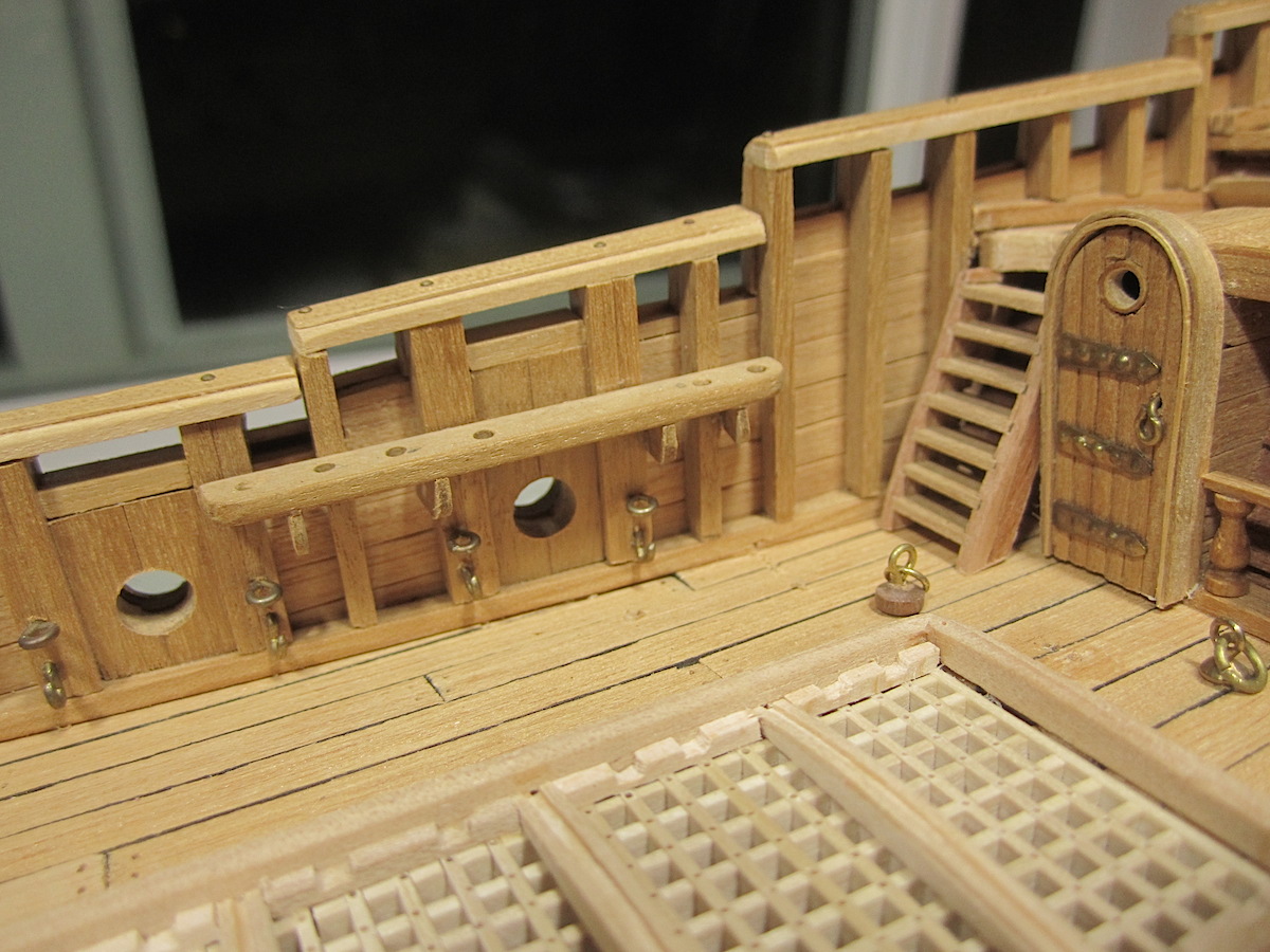
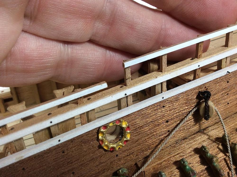
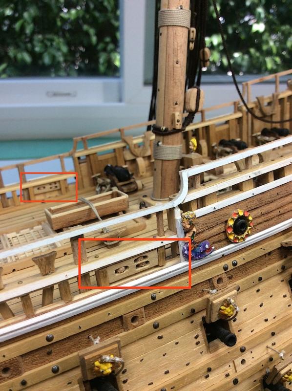
Mark thanks for your kind post. Patrick, yes that is correct. According to the museum those needed pin-holes should be drilled into the lower railings instead of from two incorrectly added rails. I will use this as a rigging guide. I hope that this will be helpful for you as well (pdf that I could not convert into a jpg). Two pages showing all rigging attachment locations at the weather deck. PS: 2 When Vasa II is (finally) published it will have the entire rigging plans in the book. Cheers, Wasa_rope locations copy.pdf
-
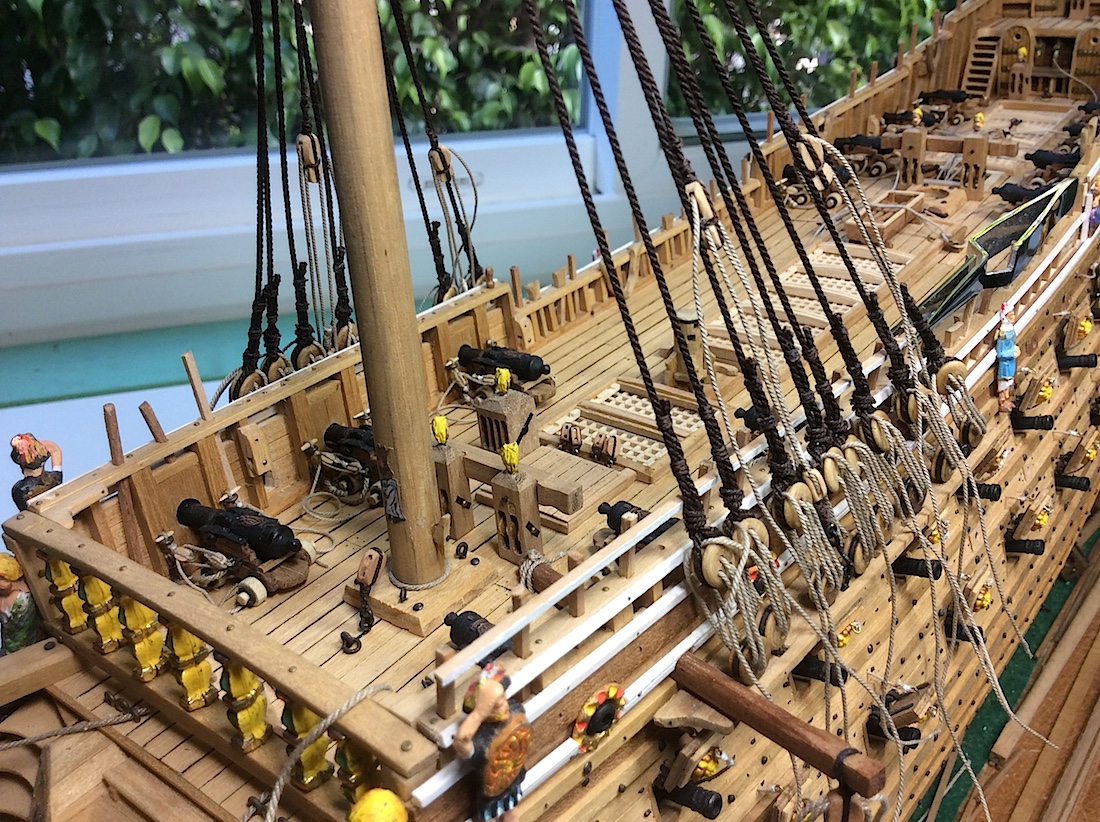
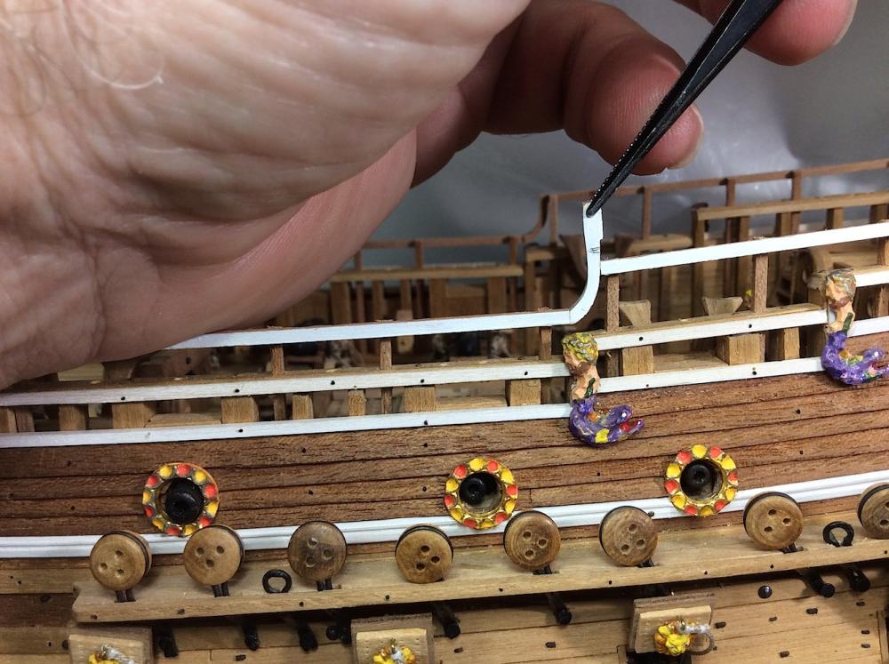
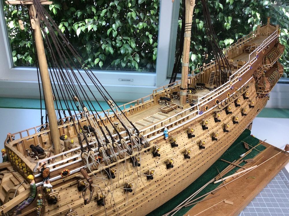
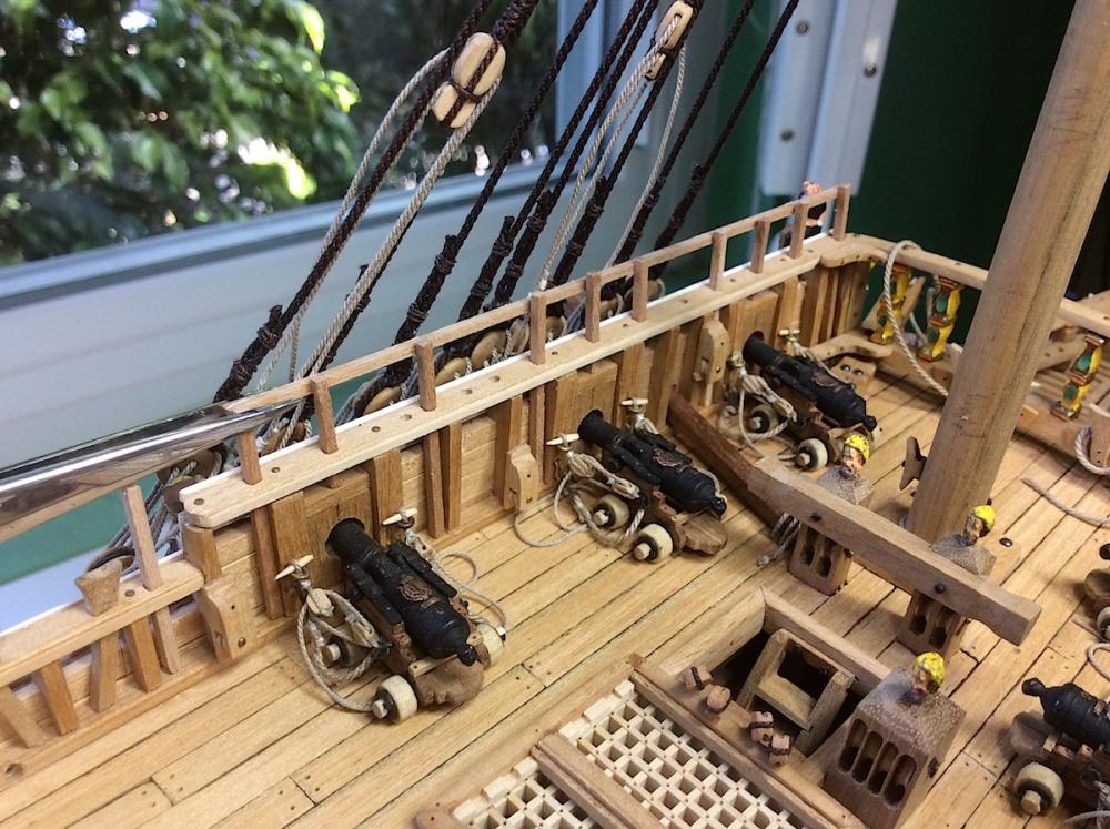
Hi Mates, After drilling the needed holes and squaring them along the lower railings got close to attaching the main mast, and the shrouds, then – for some reason – as I was squaring the last of the railing holes, I decided to attach the needed horizontal rail at the foremast (where the squared holes had already been completed; to be sure that the vertical beams would all align properly when it was time to glue those long horizontal rails on each side. Then realized that having pre-attached the foremast shrouds, before fixing in place the upper rail trim bits was a big mistake. Now trying to align the squaring of the pre-drilled holes, adjusting the heights of the vertical braces is a real pain. Hmmm So before I attach the lower main, mizzen, and their shrouds, I will build all the rest of the upper rails first. PS: Mark I should have gone back to your log (Marktiedens #103) and taken your sequence into consideration. Frank and I had also discussed this issue J we were both concerned about installing the upper railings before all the rigging work in case of breakage later on - (being all thumbs and all) Oh well, still an adjustment work in progress. Here are a couple updated photos. Regards,

-
Nigel - thanks so much for your kind post and continued interest in following along. This build has been improved by following, and learning from some of your excellent ideas - (:-) Frank - As always thank (:-) PS: as you know your Alert is so beautiful And thanks mates for the kind "likes" and also just dropping by. Cheers,
-
EJ_L What Bob said + Hindsight, in this hobby, is one of the most powerful catalysts for frustration. You are not the Lone Ranger. I'm sure all 22,000 members here have, at one time or two, suffered from this as well - Ha Ha PS: Very nice update looking very good.
- 608 replies
-
- 4
-
-
- la couronne
- corel
- (and 1 more)
-
Ian, Whoa to all of the above posts. Beautiful work in such a new technology for crafting a model, in this case, of a "ship". VERY impressive indeed; a pleasure to look at. Cheers, MIchael
-
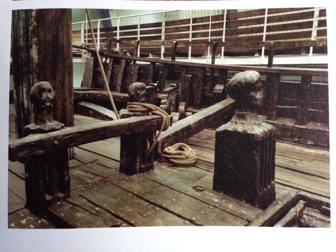
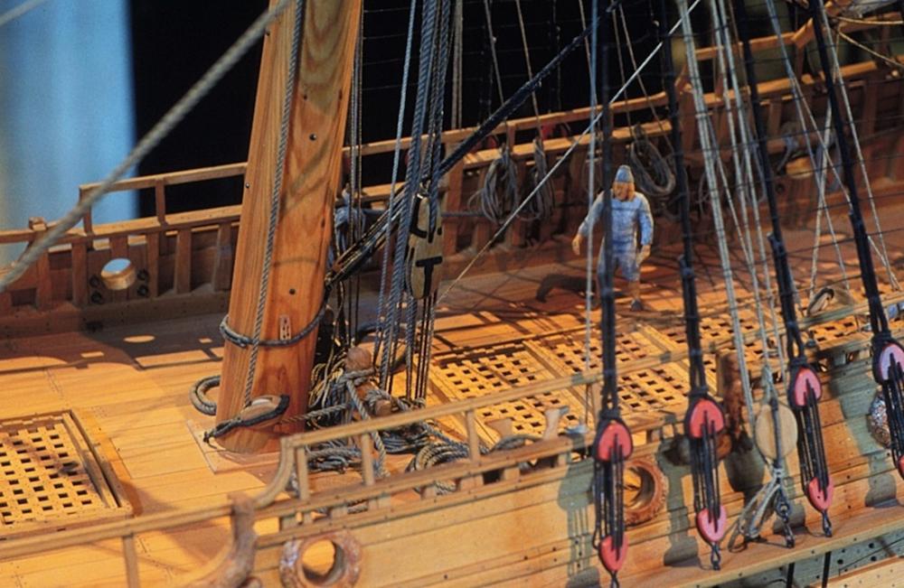
Kevin, So nice of you to spend your lunch break here. I'm very appreciative. Thank You indeed. Thanks Backer, LevDavidovic, and Woodo in choosing to follow along as well. I appreciate the courtesy on your parts. Welcome to the shipyard. Though you may turn "grey" before its launched for its sinking (:-) ===================== Not to "beat a dead horse", but (:-) after my last post regarding the knightshead railings without pin holes, I got curious about why I decided to do them that way. Well going over some photos gave me the answer. I assumed that the photo below were actual salvaged original parts (they certainly look it). They had no indications of pin holes. I also used this photo for help in adding a single anchor cathead that I mounted on the port side. Its port anchor will be attached later on.


-
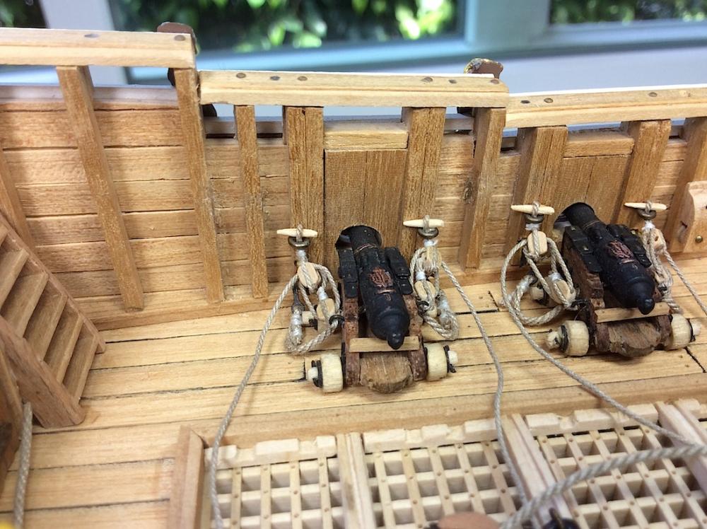
Joe, thanks very nice of you - as always : cheers to you Frank, Yes the Vasa is always coming up with changes as they "discover" more errors at the museum. Including the 1/10th photos below. The knigntshead rails (just behind the mainmast has two versions); one with pins, and one without. I built mine without, so the railing is too thick to NOW drill holes for pins. It appears in one of those photos that the ropes are just wrapped around the railing. Its hard to really see details however. Though the Corel sheets do indicate pin holes for both fore and main mast railings. Hmmm ?? JanV, So nice- thanks so much you are way too nice. So appreciated indeed. Also thanks mates for dropping and taking a look - always appreciated.

-
E.J., Excellent detail with your carriages. If this is just an indication of when you will add your "heavy details" well hmmm...Exciting indeed - for those of us following your log. This looks to be an awesome build indeed. Enjoy!! Cheers, Michael
- 608 replies
-
- 4
-
-
- la couronne
- corel
- (and 1 more)
-
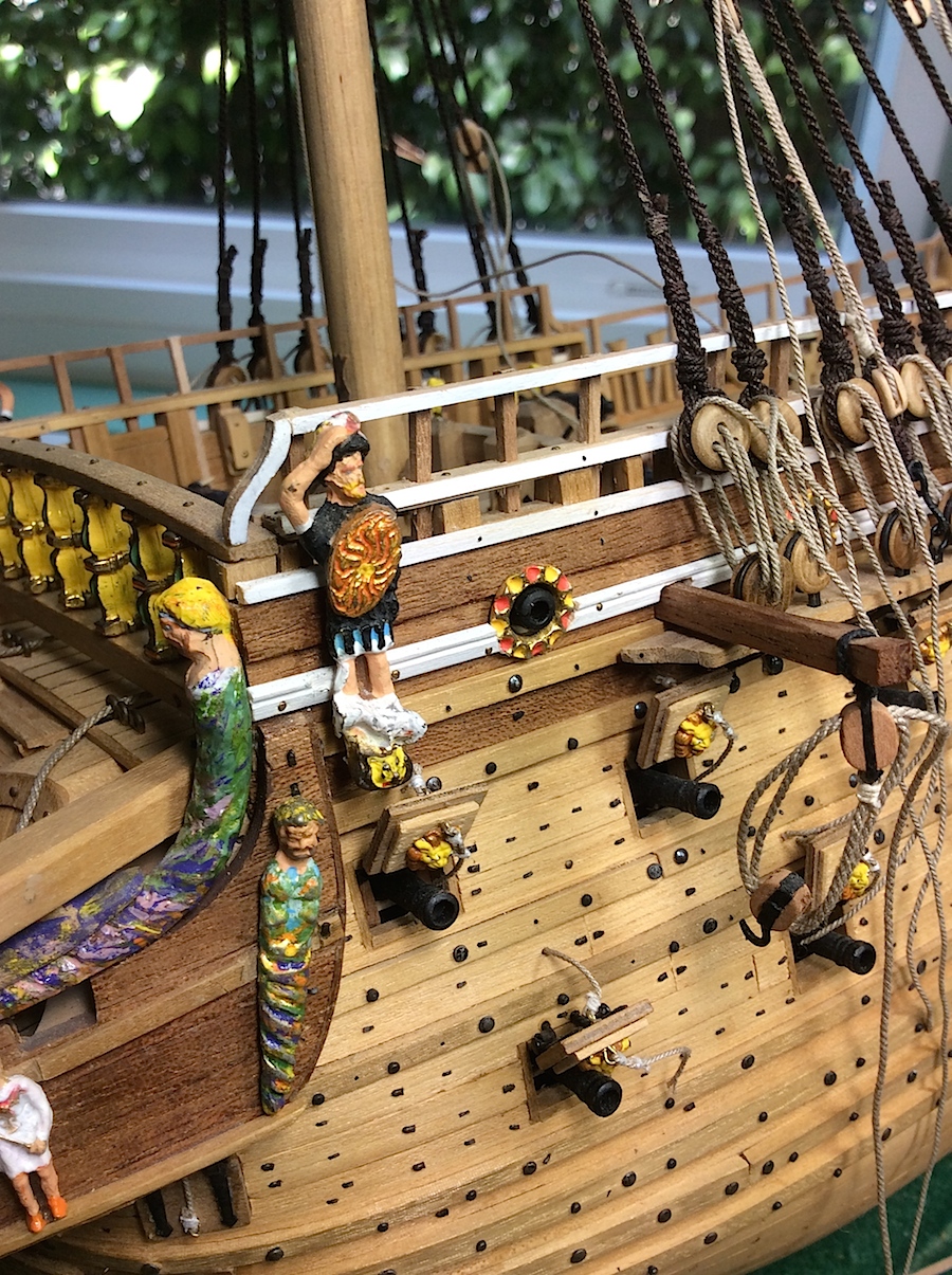
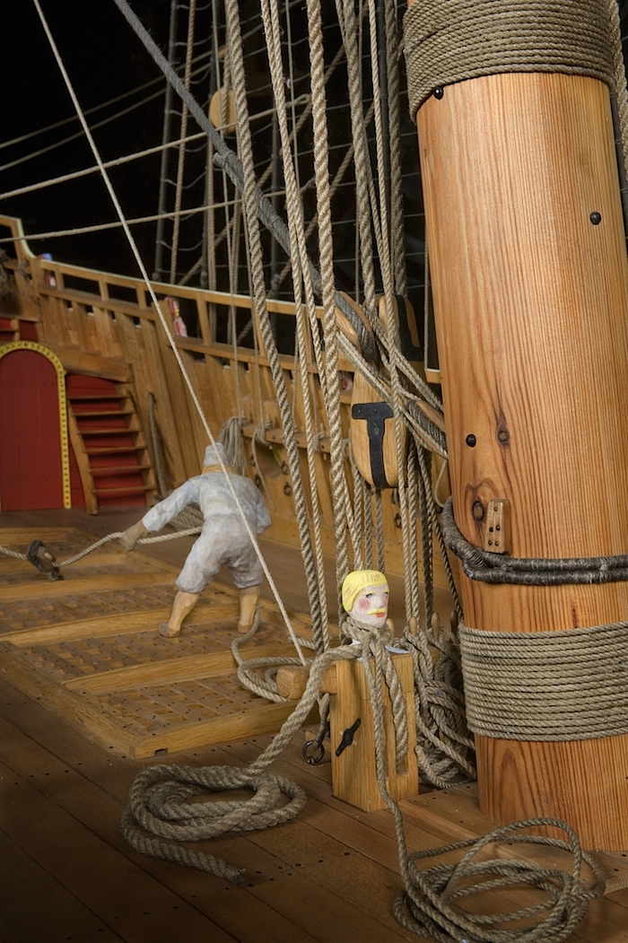
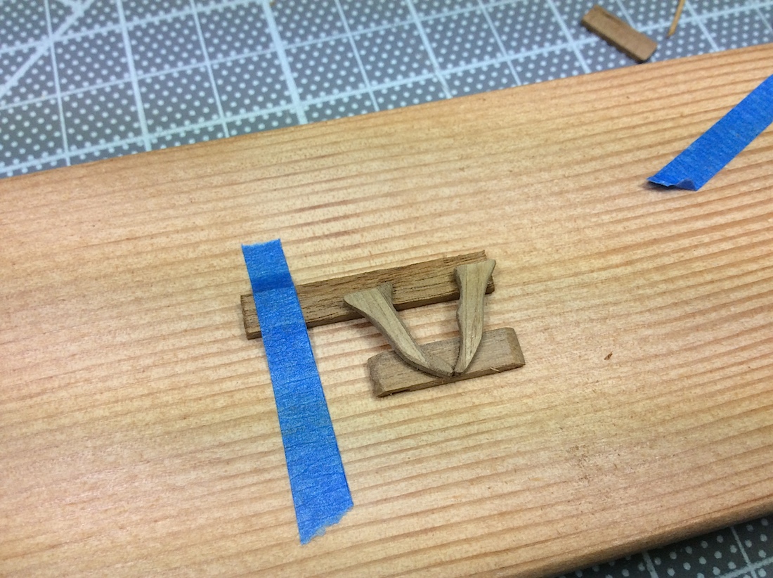
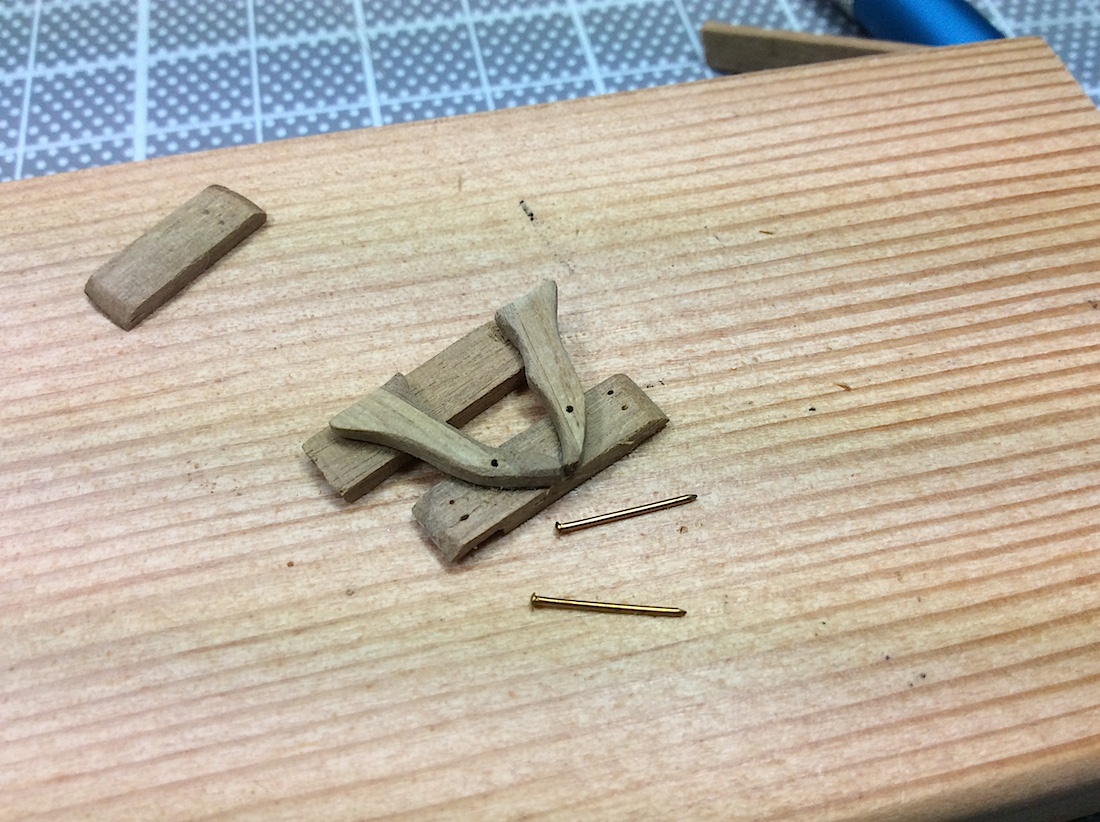
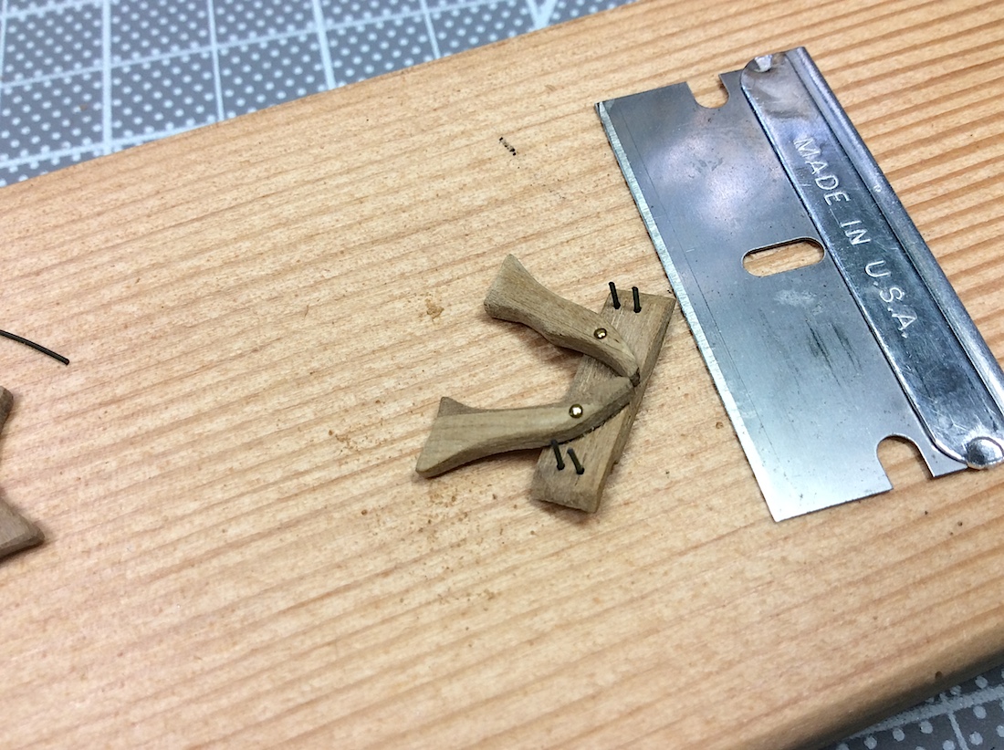
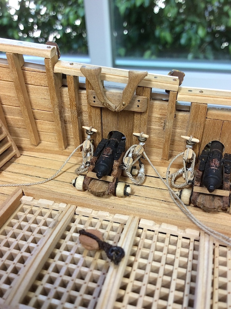
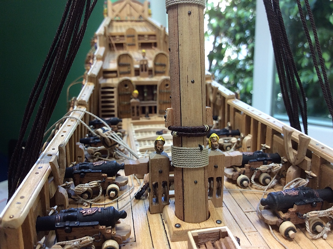
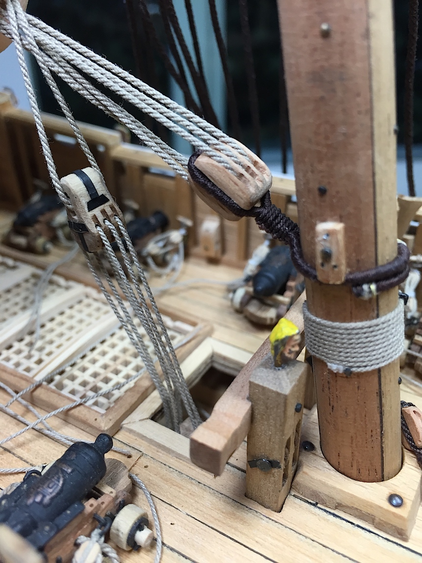
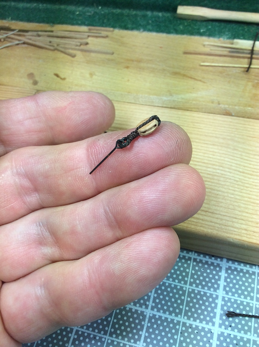
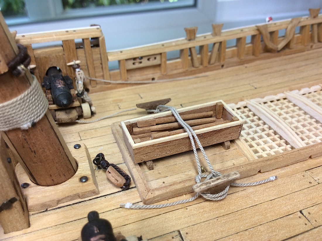
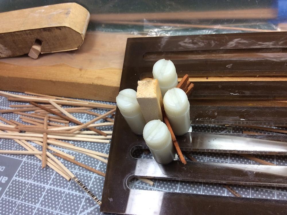
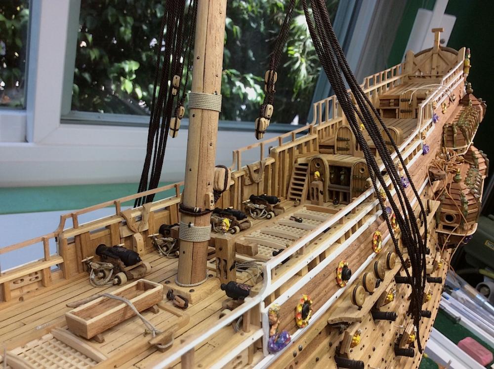
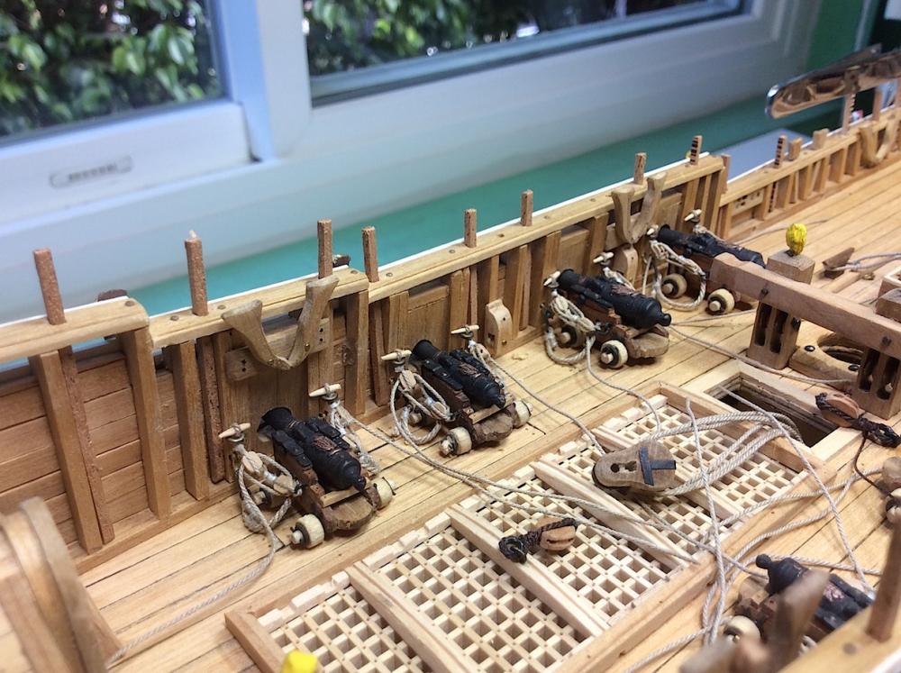
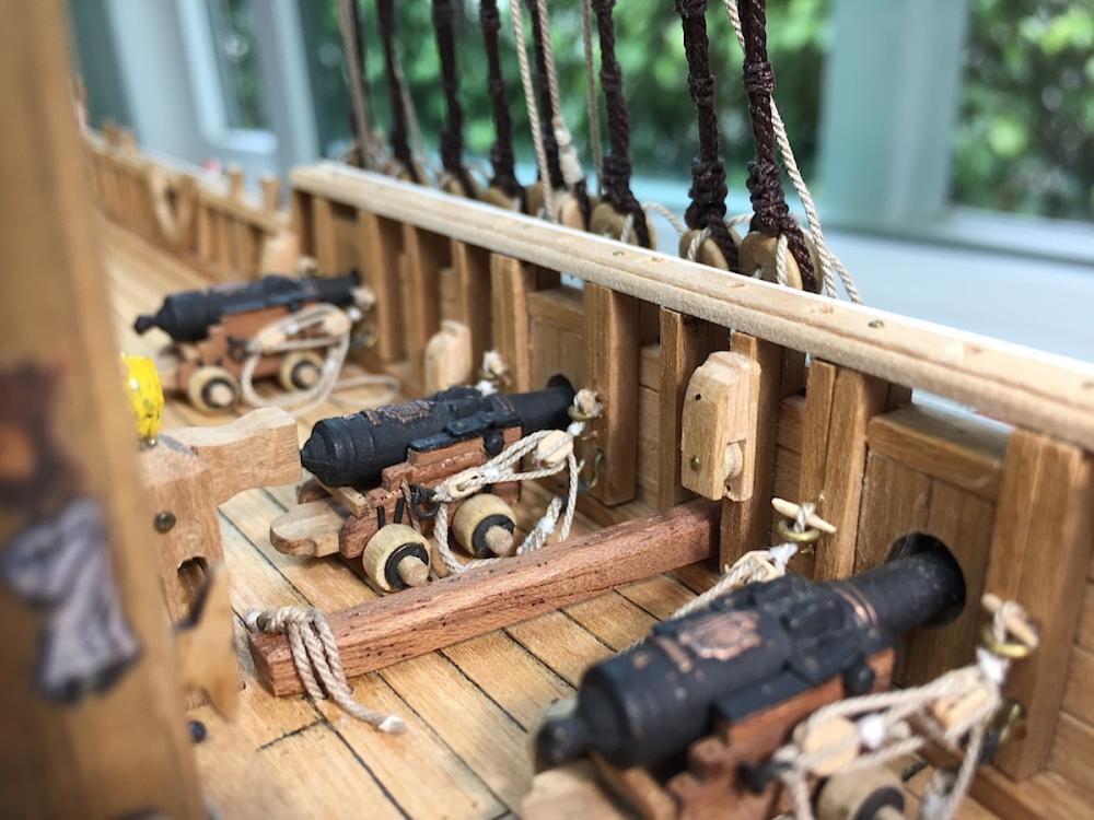
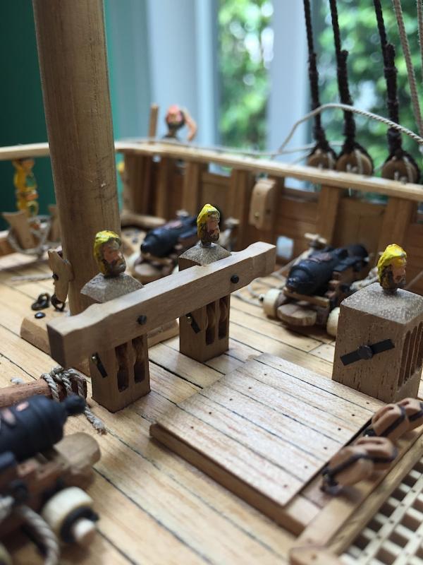
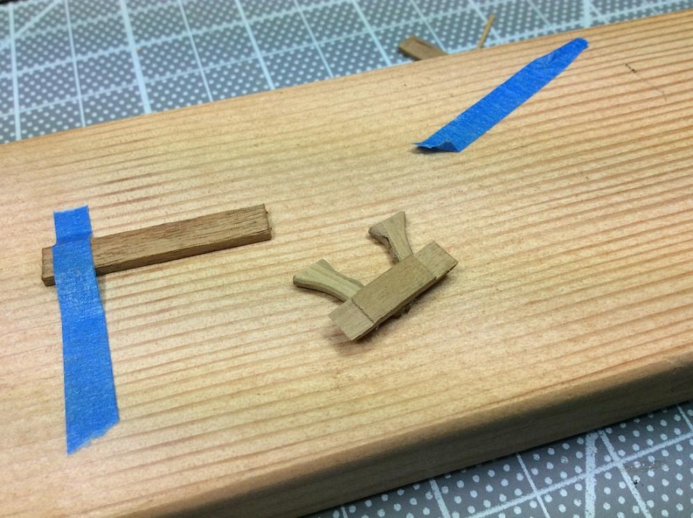
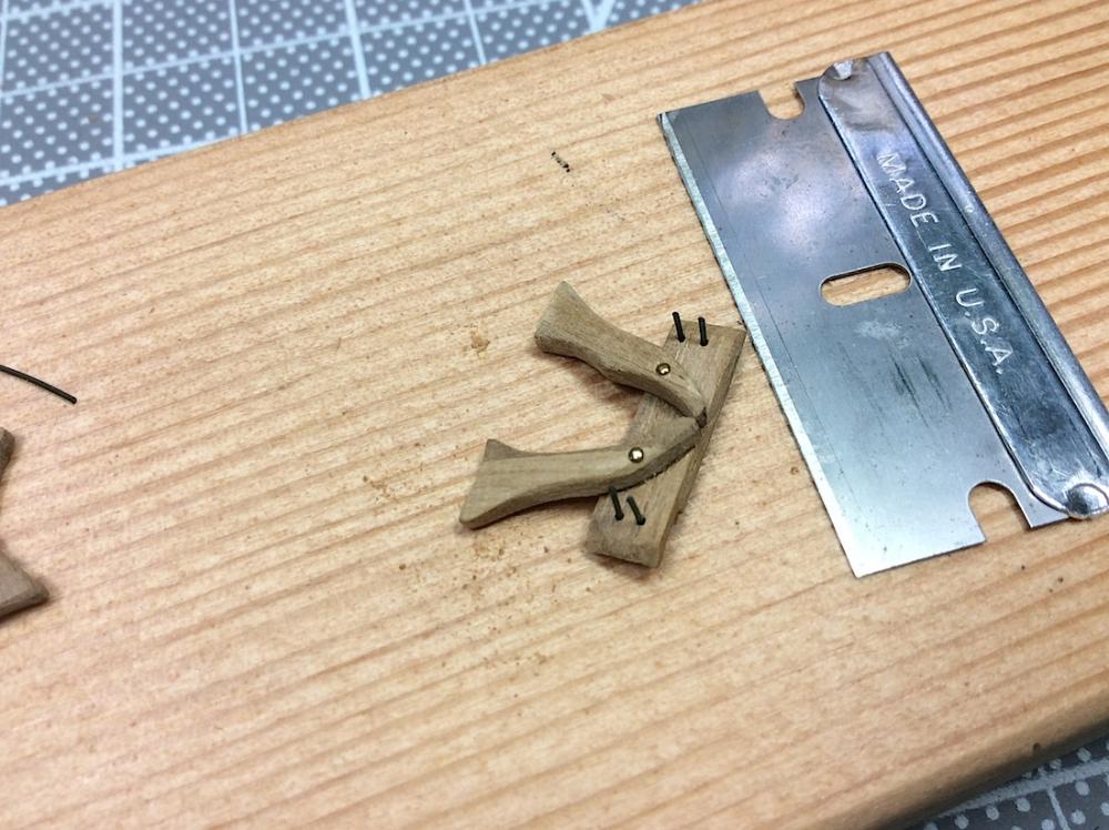
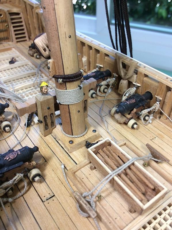
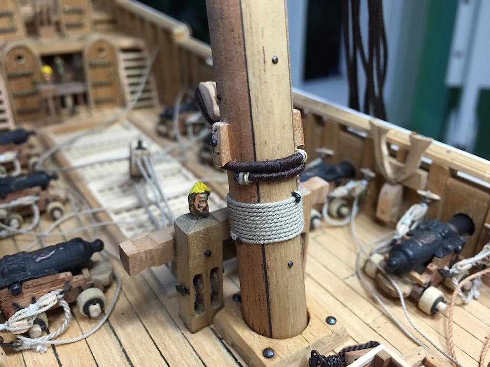
Hi Mates, Frank, thank for your comments. Thanks for likes, and dropping by (:-) A few added small time consuming details, as I want to make sure that all needed items are in place before I attach the mainmast shrouds to their deadeyes. Turns out that the pin rails that I had located at the quarterdeck were in error (first early photo). Fred Hocker said, “we got that wrong, those pin rails were added by mistake, it should have been kevels” So pulled them out-did leave some scaring, and then put together a kevel for each side. Used black nylon fishing line so simulate the four mounting cleats. Attached the served rope around the mainmast along with the triple pulley. Added a rope trim at the mast base. Made up some single blocks for drilling into deck. Changed the attaching rope to the box for the capstan winding bars. (Though I think their shapes and lengths are amiss) Next need to; Tidy up carriage ropes Drill vertical holes for upper railing braces Drill more holes for newly needed belaying pin locations Make six fiddle blocks and shrouds for main mast stay. Then I can proceed with the 18 shroud attachments. Cheers, Michael


-
EJ_L Your post is so touching - thanks so much, I'm so appreciative, and very happy that you find areas of help to you here in my log. Our hobby is certainly reciprocal in nature isn't it. My skill set, and I still have much to learn, has certainly also been helped by following and browsing other build logs here as well. PS: Your hull planking, for example, I would love to eventually be able to emulate (:-) PS: 2 Noted your colorful signature and copied your's the other day ha ha..... PS: 3 Yes - I did join the NRG the other day (:-) Respectfully, Michael