robdurant
-
Posts
796 -
Joined
-
Last visited
Content Type
Profiles
Forums
Gallery
Events
Everything posted by robdurant
-
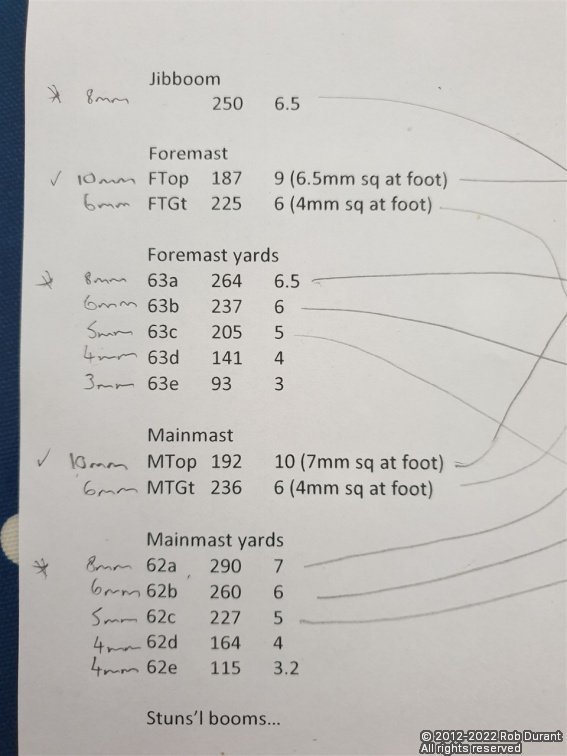
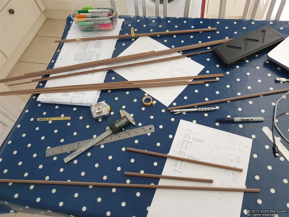
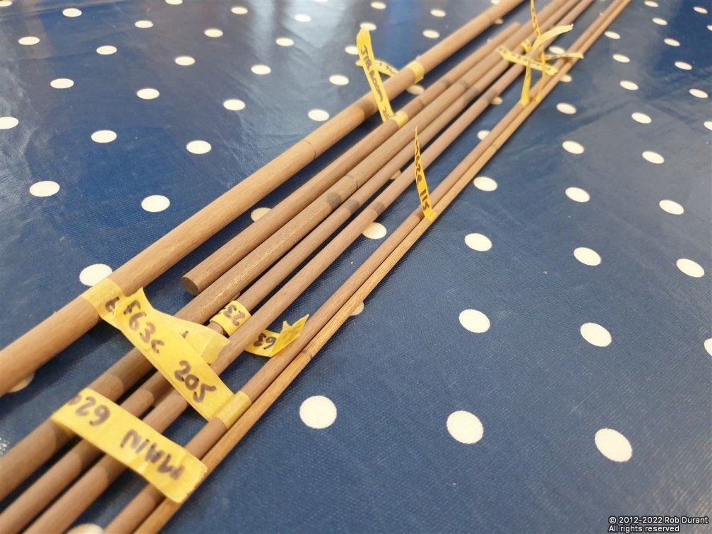
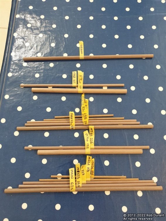
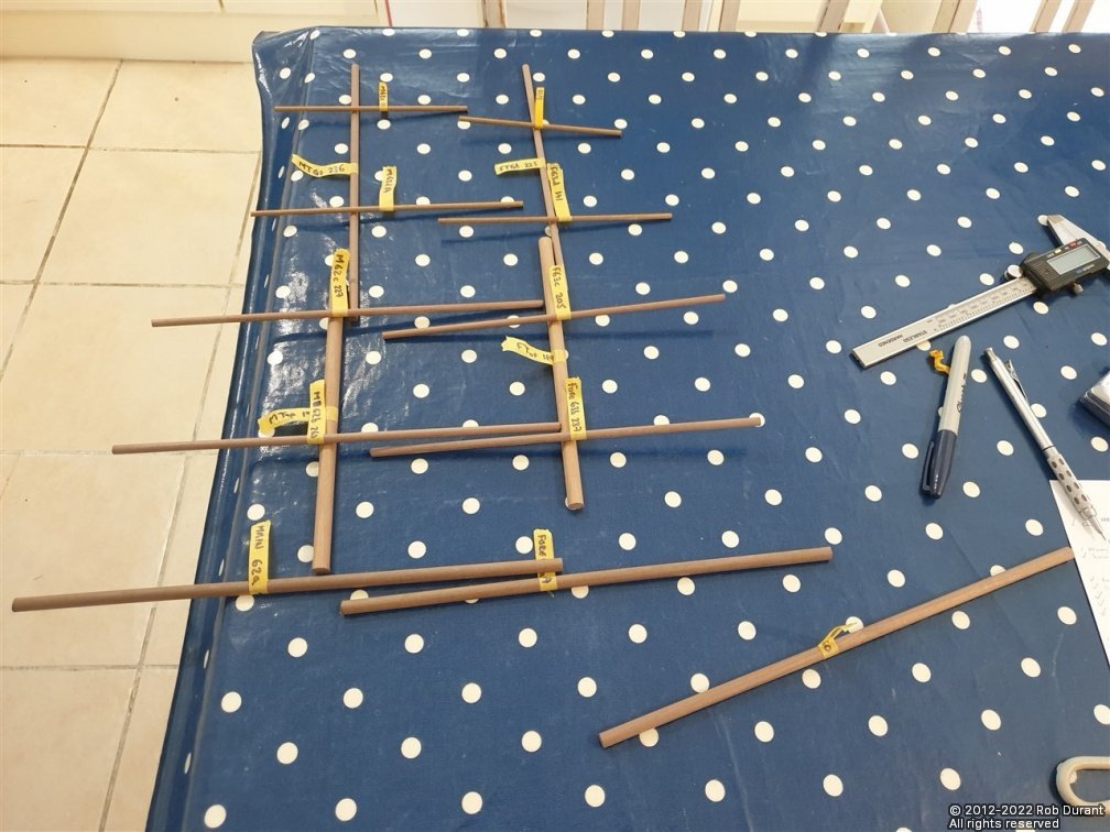
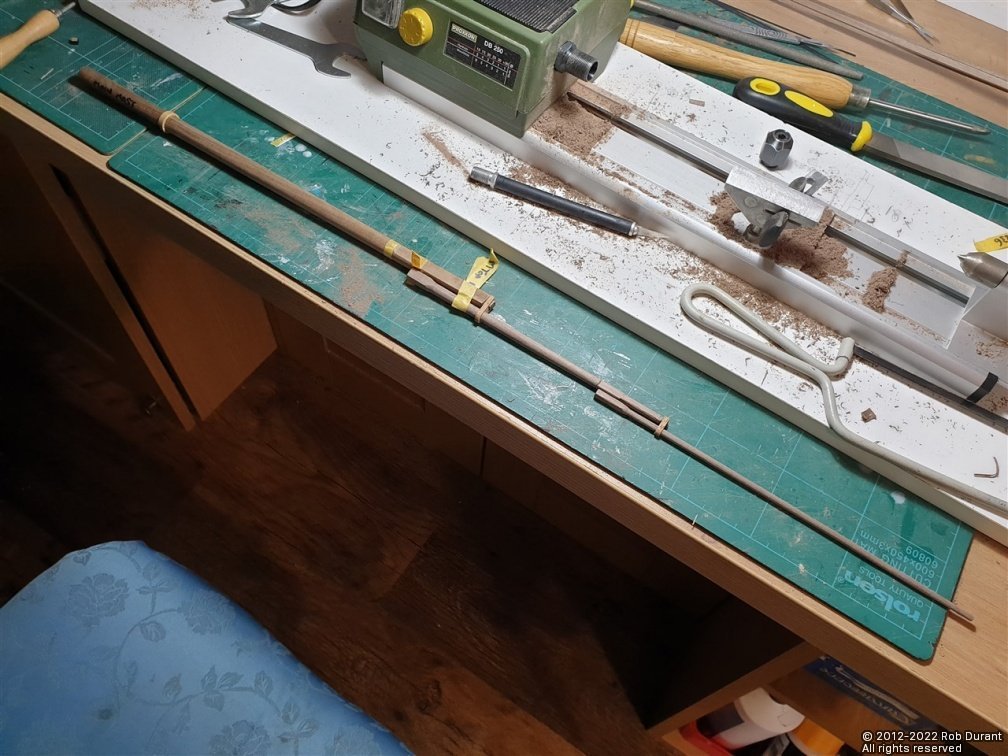
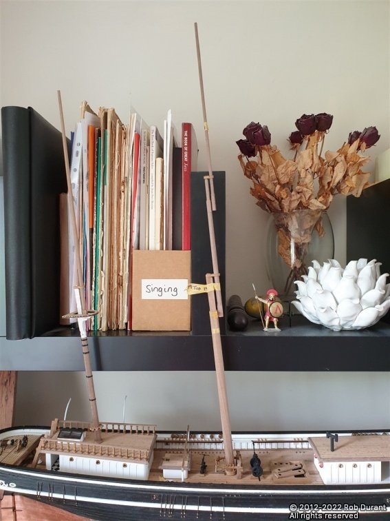
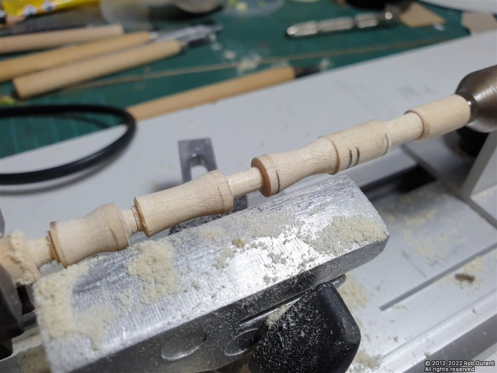
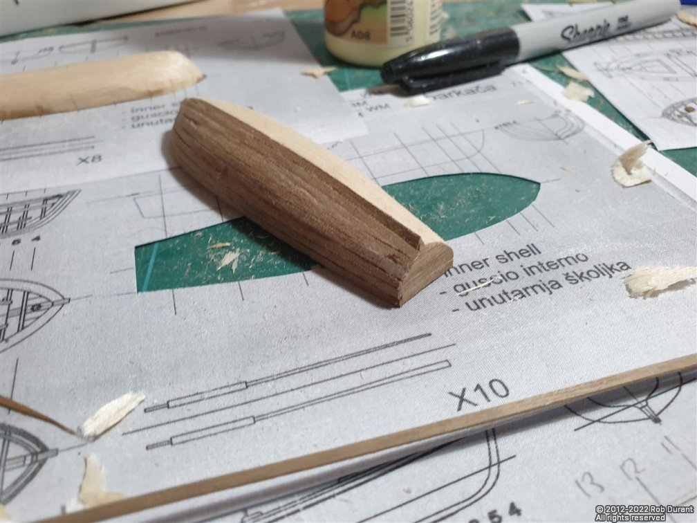
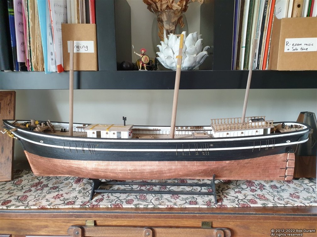
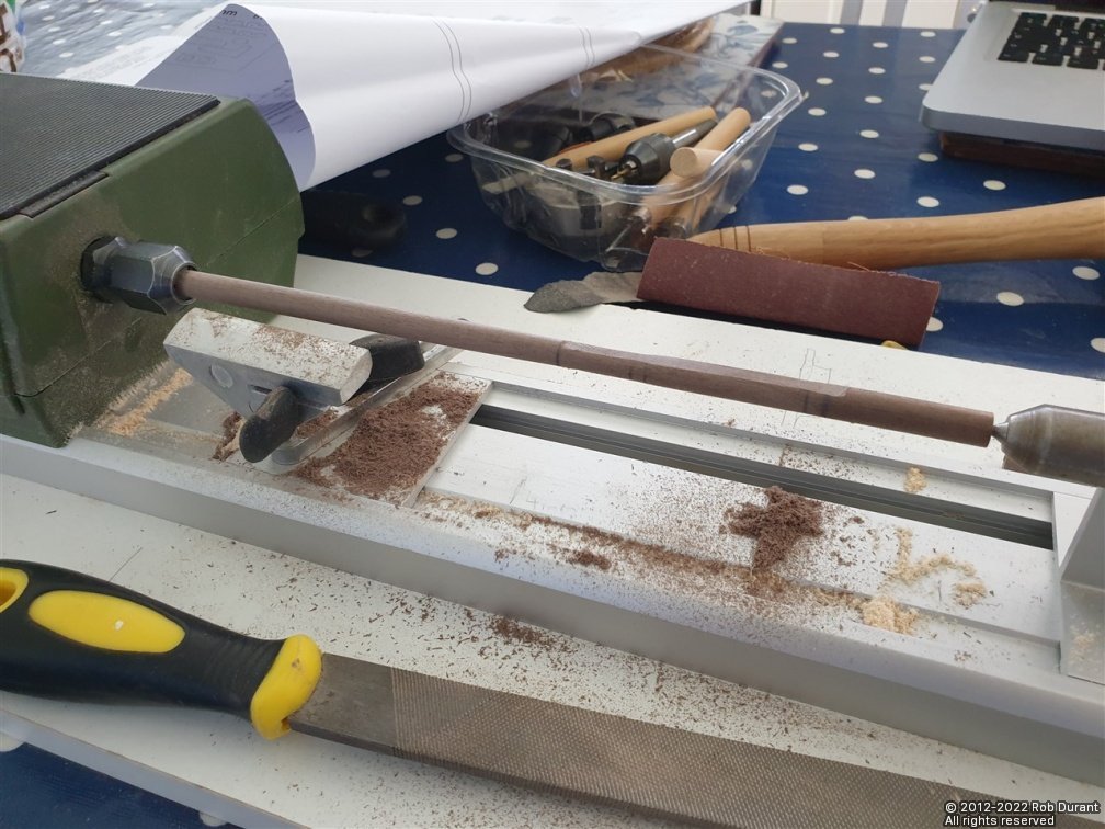
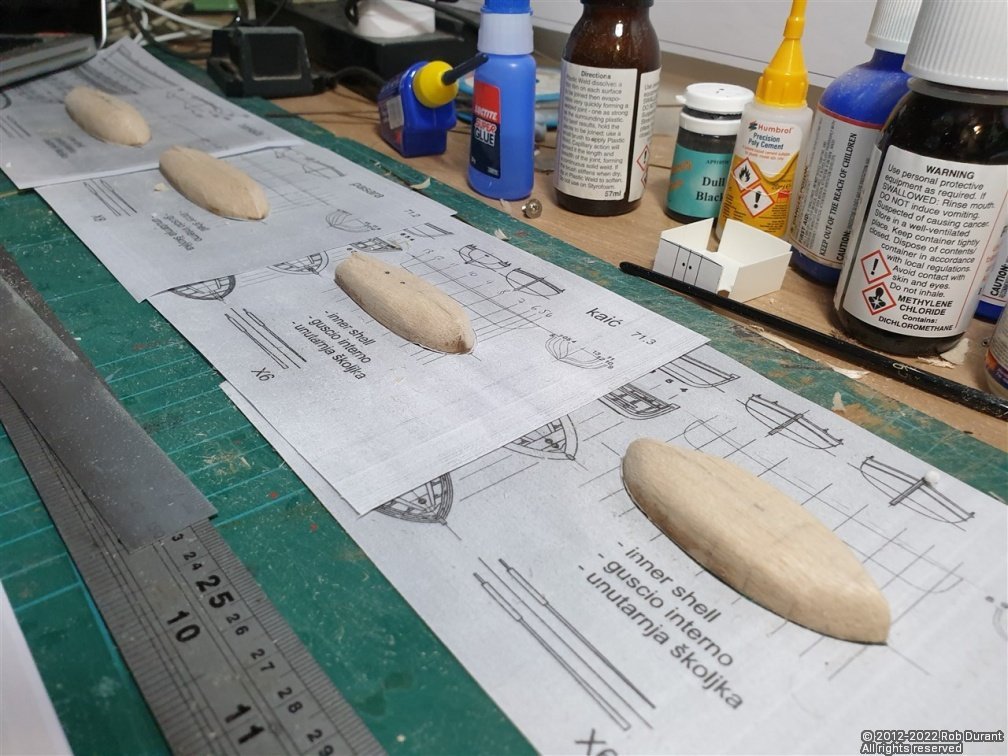
 Hi all, I've been working out what dowels I needed to make the masts, yards, bowsprit, gaff and boom... These were calculated based on the largest diameter required to allow the square sections to be made as part of the mast. The first step was to work out which dimensions were shown on which plans. The answer being: plan 10 for the mizzen mast and spars; plan 9 for the foremast and yards and jib boom / bowsprit; plan 8 for the main mast. (excuse the messy drawing below, but it helped me think it through in one go, and meant I had all the measurements in one place) Having done that, the next task was to take stock of what dowel I had, and what I needed, and then assign the spars to the stock. The measurements are my own taken off the plans, so don't take my word for it - do your own measuring - you have been warned! The left hand column (e.g. 8mm) is the dowel diameter I intend to use, the next column is my code for that particular mast / yard, the third is the length of the spar, and the fourth is the diameter at it's maximum (where a square section is required, I've noted the maximum diameter to encompass that, along with the final size of the square section) - nb: I've noticed now, that some of the square sections at the foots of the top masts are NOT square... they're rectangle, so watch out for that, too. The pencil lines go from the spars to the stock I have... this is my way of checking I'm not going to run out, but also that I'm using the wood in the most efficient way. The spars are measured out onto the dowel with at least two centimetres spare, so that I have a bit of surplus to be left at each end while turning the spars. The measurements on the table above do NOT include this surplus - I just add it on as I mark up the wood. Everything's marked out onto the dowel, with masking tape tags to keep a record of which section will be for which spar... Once that's done, I cut the lengths out, ready to be turned. Laying them out gives some idea of what the effect will be (and helps you spot if you've missed any... as I had... I missed the mizzen gaff and boom! Then it was on with the turning. Today was the turn of the main topmast and topgallant. These were turned, taking care to fit them to the caps as I went. And it's always pleasing to be able to raise the mast with no glue required at all... just the friction of the cap holding it all together. I'm beginning to get that dread sense of the scale of this model when she's complete... and that's before I begin to think about the stunsails! Thanks as always for all the likes Rob
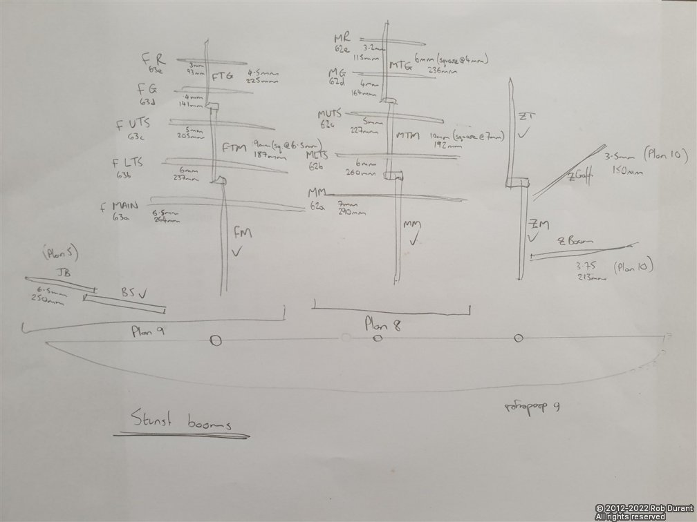
- 285 replies
-
- 12
-

-
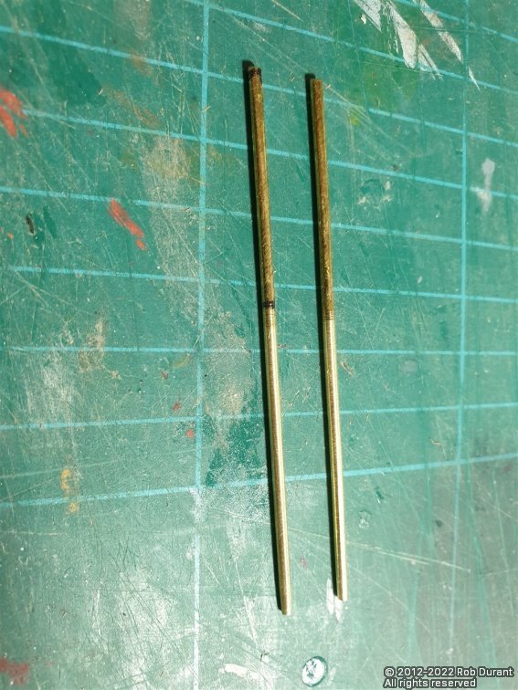
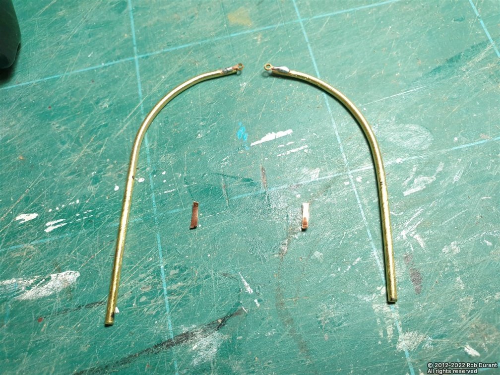
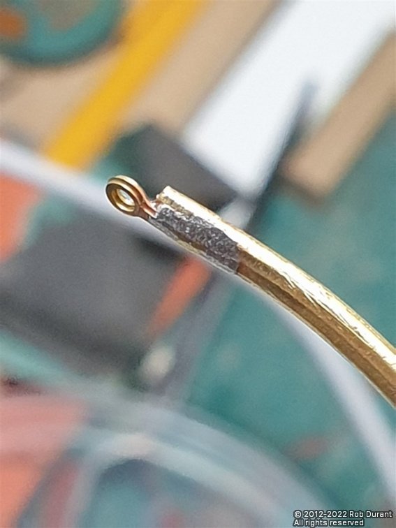
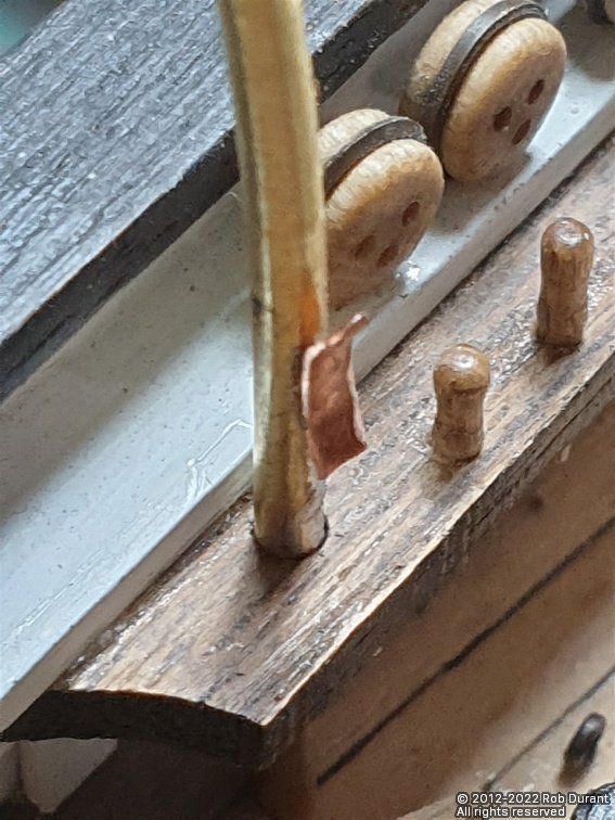
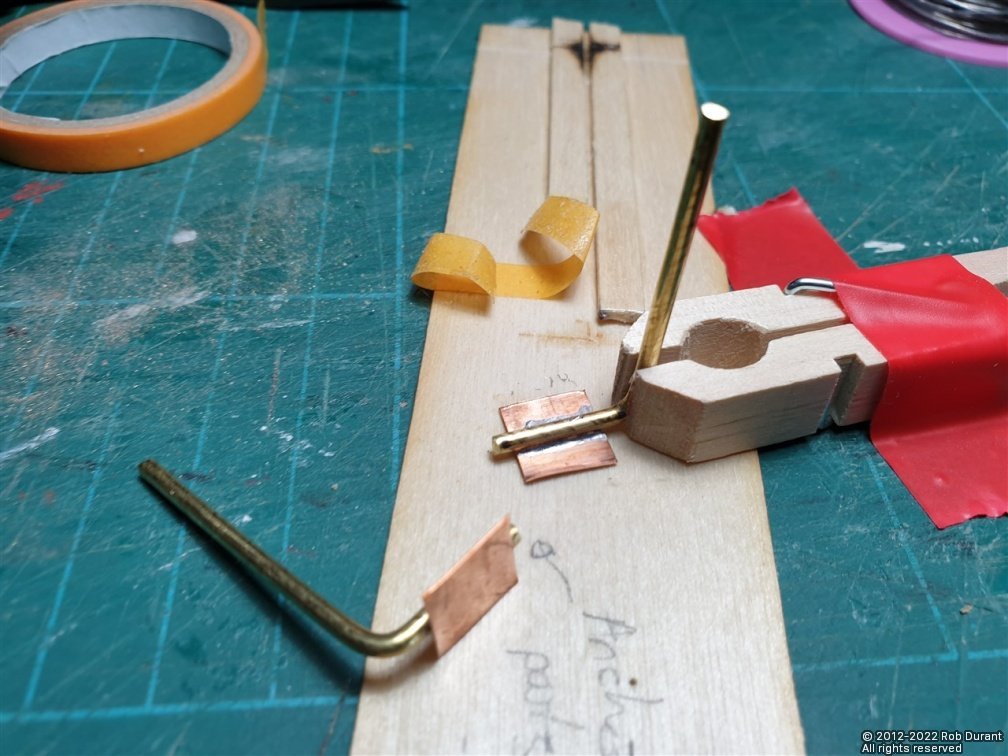
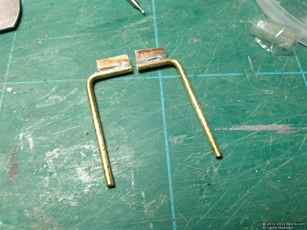
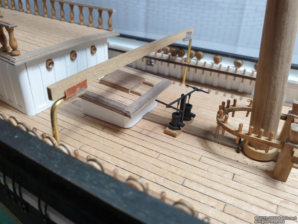
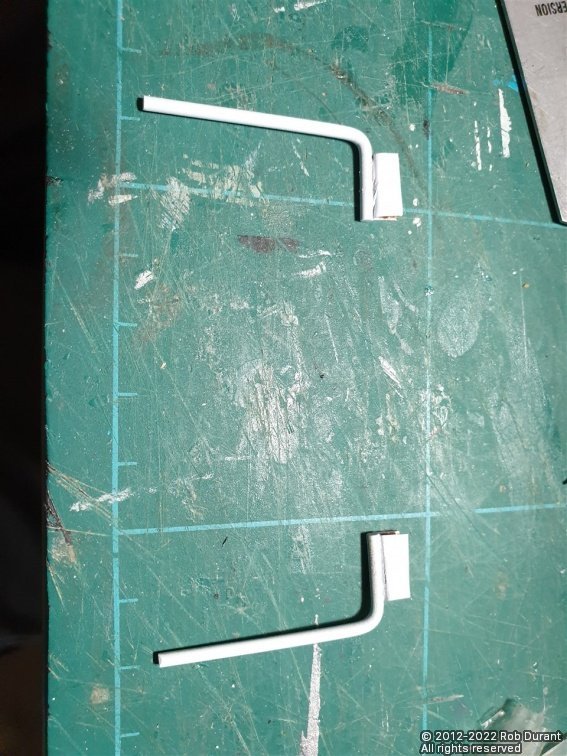
And the second part of the update.... I've also spent some time putting together the mizzen top, and making and fitting the mizzen topmast. There's still a lot to do on both... The mizzen top is made from laser cut parts from both the ply, and the 2mm and 3mm walnut sheets. This structure will have a walnut surround. I turned the walnut topmast, and fitted it to the cap. The mizzen mast needed a little fettling to fit the structure that supports the top. Today I added the cheeks to the mizzen, and the pin rail that sits just above the deck. I'll show that in a future photo, as I'm waiting for more belaying pins to arrive (I'm replacing the kit ones with Caldercraft 9x1.5mm belaying pins) Finally, I turned some 2mm brass rod from the kit to taper it and then bent it to shape for the ship's boat davits that sit on the port quarter. These had eyelets cut off the top of 1:48 RN stanchions soldered to the top, and copper strip soldered to the back as a cleat. The tapered rod... (It's worth noting that once these were made, I realised that the sternmost davit is shorter than the foremost one - thankfully every other detail is identical, and I'd made these to the longer version, so it was just a case of shortening the sternmost one. As per the cross-support for the boats over the deck, these were inserted into the pre-laser-cut 2mm holes in the pin rails. Next will be to give them a lick of paint, and then it will be back to the mast fabrication. That's it for today. Rob
-
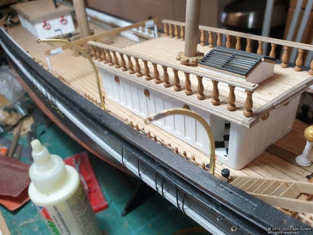
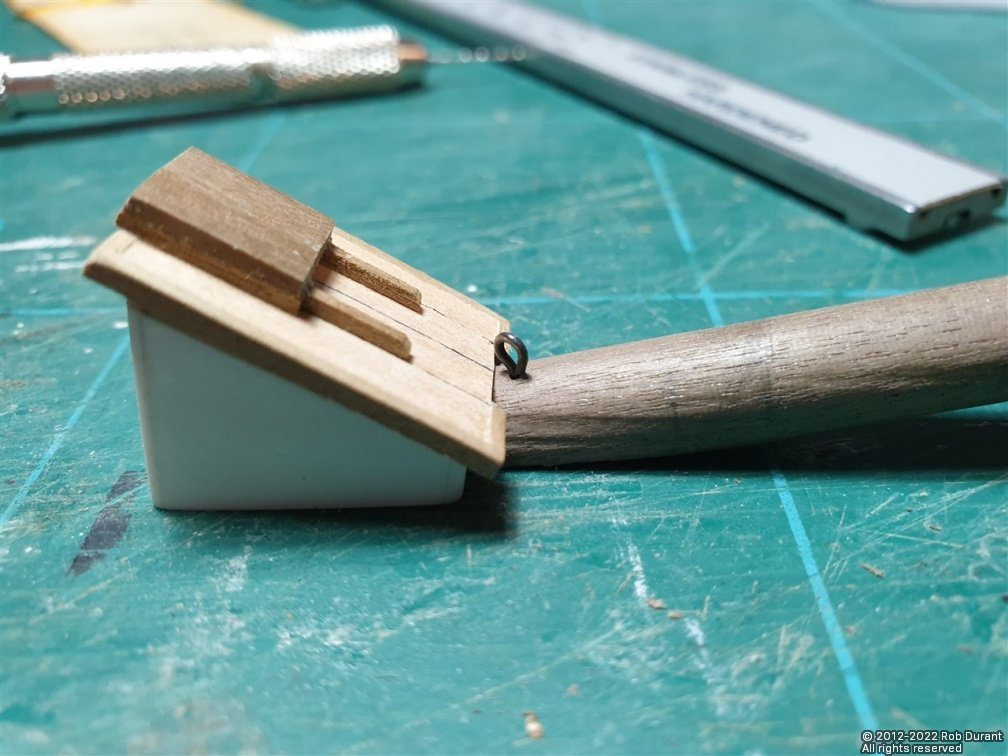
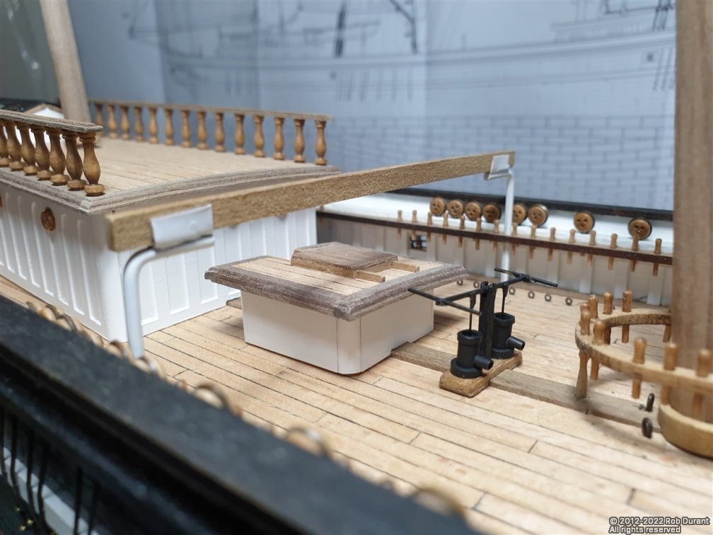
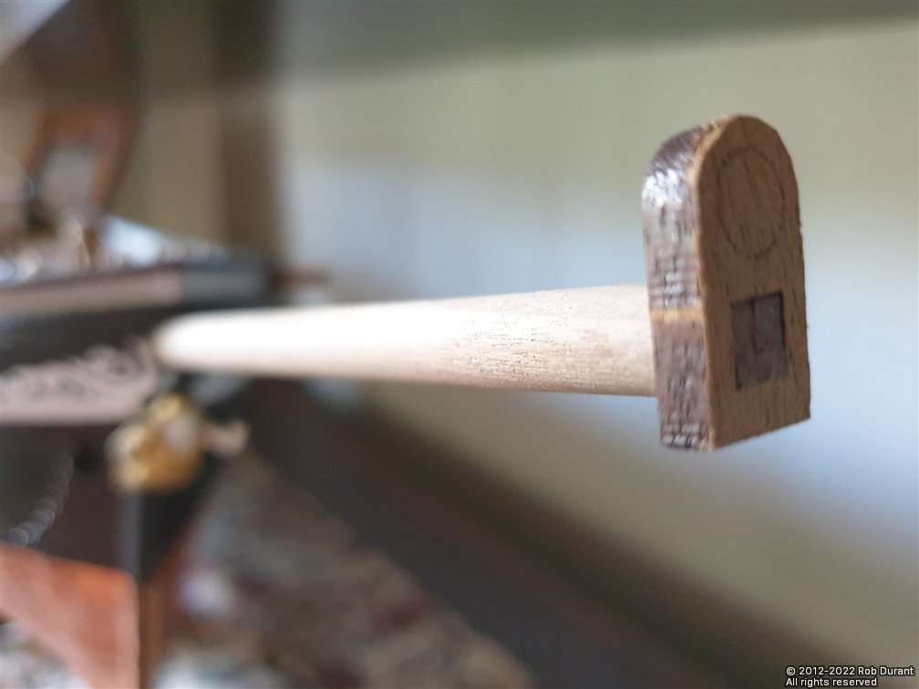
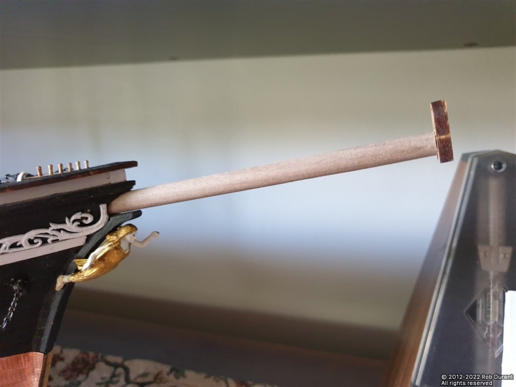
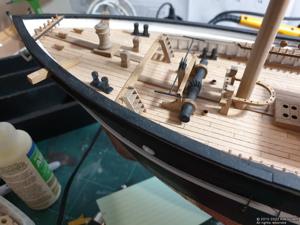
Hi all, Thanks so much for the likes - it's a great encouragement. Part two of the knock-on effect of sticking down the foredeck too early was pointed out in the instructions. They say quite clearly that you mustn't forget the large eyelet under the foredeck. From what I can tell that eyelet only shows up on one side-view on the plans - It sits a centimetre under the foredeck, and needs a hole drilling vertically into the deck. I'd missed it because it doesn't show up on the top down view where all of the other eyelets in the deck are marked. It's kind of important, because it forms the anchor point for the main stay for the main mast! I scratched my head for a bit and realised that I could kill two birds with one stone. By allowing the bowsprit to come further aft, as I had done, the bowsprit would occupy the space where the stay would be anchored. By drilling the vertical hold into the end of the bowsprit, I could then put the bowsprit in, then, once it's finally in place, and I'm rigging, install the eyelet in the end of it (because the hole was now in the right place). This is all hidden behind the companion way that sits directly behind it under the foredeck. The eyelet is installed in these photos, but not glued in place, because the bowsprit will doubtless be in and out of the boat a few times yet. And here's a shot of where the bowsprit ends up when installed. Feeling pleased with myself I went on to install the eyelets on the outside of the hull, and the rails. I also drilled the holes for the cleats at the stern. Nothing much exciting, except that I was tired and broken a few drills in the process. It's a bear to drill down into the upright between the main and topgallant rails. The big eyelets were installed at the bases of both masts. Definitely not a job you'd want to do with the pin rails in place, so do follow the sequence in the instructions here. (I've intentionally not glued down any of the fittings until I'm confident all of these gotchas are finally out of the way!, but the instructions are proving to be in a helpful order.) The next job was to start making the ship's boat cranes. There are two types. A support that runs across the deck, which was made out of wire, and copper left from a fret from the copper tiles for the hull. Hopefully the sequence of photos will be fairly self-explanatory here... The uprights fit into holes that came ready laser cut in the pin rails (which were opened out to 2mm with a pin drill.) I have a little more to share, but I'll put up an extra post after tea, which is smelling lovely! Pork and apple cider casserole. Happy building to you all. Rob
-
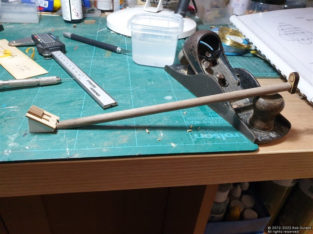
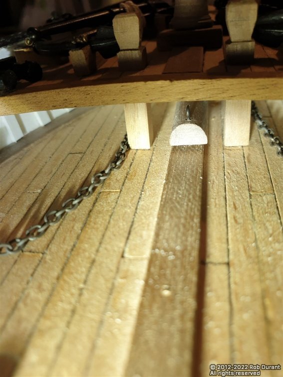
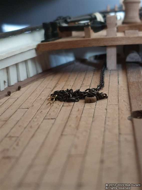
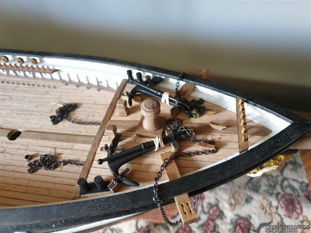
I wanted to see how easy it was to run the anchor chain, having mistakenly glued the foredeck in place too early. Hopefully my mistake will help someone else to avoid it. The answer is that using brass wire and a torch and some needle nose pliers, and lots of patience, it wasn't too bad. Mainly because I'd hollowed the balsa out before putting the deck on. With that said, it was still something of a fiddle, and once the brass wire was threaded through from one side to the other, I could then pull the ready-blackened anchor chain through. It will come from the holes in the deck just aft of the windlass, pass round the windlass, then go through the bulkhead, down to the hawse pipe holes, out of the bow, loop up to the cathead, where it is wrapped around to find the anchors on the deck. I realised in doing this, that the chain was too big for the hawse hole, so I opened them up and had another go. (All of the deck furniture was removed for this task, so that I had access, as you will see in the photos...) The ends are left completely loose, as are the rosettes on the hull, as these will be stuck back on once I've finished getting everything finalised. The other thing I've started working on is the bowsprit. By the plans this is made from 10mm walnut, but my hull has ended up fitting an 8mm dowel. It needs shaping so that it reduces to 7.5mm at the outer end. On the plans, it almost seems to be greater in diameter at the stern end, than at the point where it goes into the hull, but that would mean that either the hole would be too small so that it could be inserted, or once inserted, the hole at the entry point at the bow would be too large. I've opted to keep it at 8mm all along the length once it enters the hull. According to the plans the jib simply ends at its stern end, hanging in thin air, shortly after it exits the sternmost bulkhead it passes through, but again this provides no force pushing forward to counteract the pressures of the rigging on it (or indeed, my whacking it as I walk round the house with it, moving it from my boat building space to its home on top of the piano! So, I've left it slightly long, and bevelled the bottom edge, so that it now pushes right through until it gently sits on top of the king plank. As it stands, it needs shortening about 7mm, which will be taken off the stern end, as the square section has been cut in at the bow-end. It needs to be a 4.7mm square section to fit the bowsprit cap. This proved simple enough to do, and I filed in this section while it was still in the lathe, which helps me to line it up for the filing. As you'll see, I haven't removed the laser char from the outside of the bowsprit cap, as I wanted to leave it as strong as possible while the test fitting was taking place. The laser-cutting on these 4mm parts does not go quite all the way through the part, so a little cutting out is required, but not too much. It's certainly easier than cutting out parts with no help at all. That's it for now. I really enjoy this stage of a build. It feels like it's all coming together quite pleasingly! Happy building to you all.
- 285 replies
-
- 11
-
-
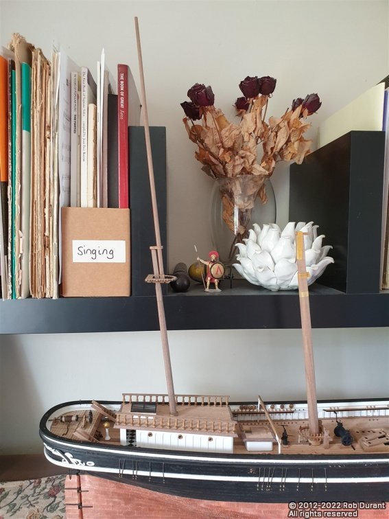
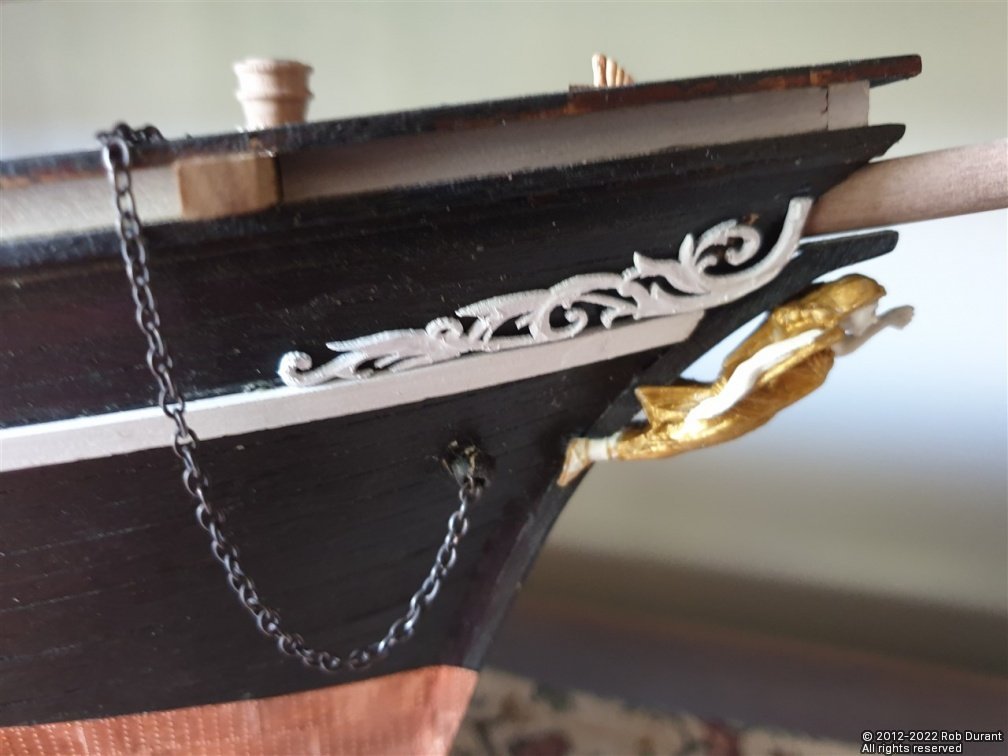
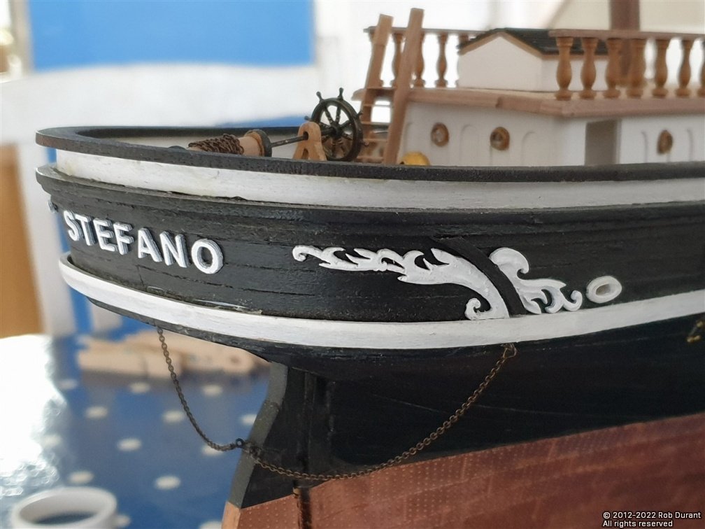
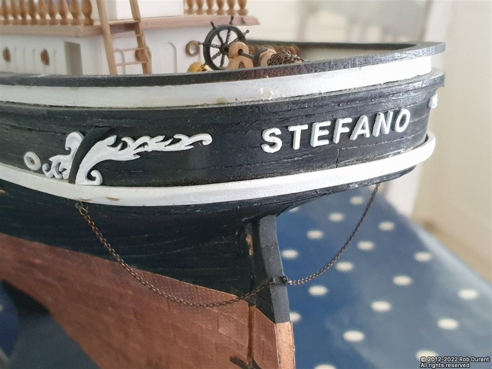
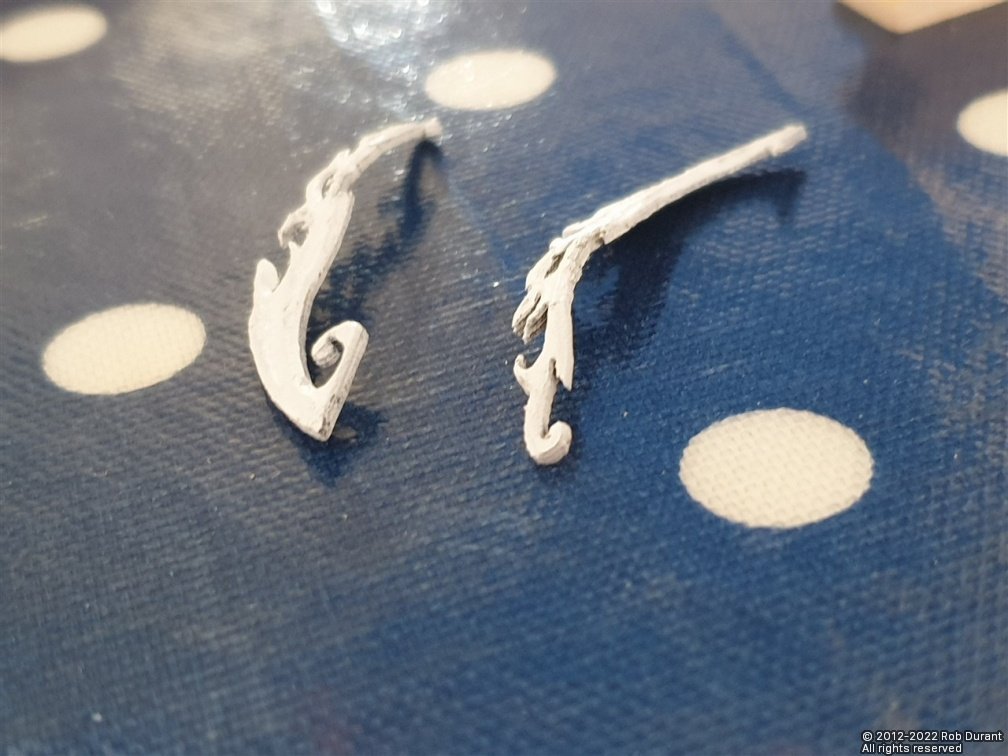
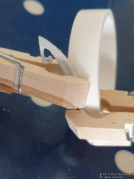
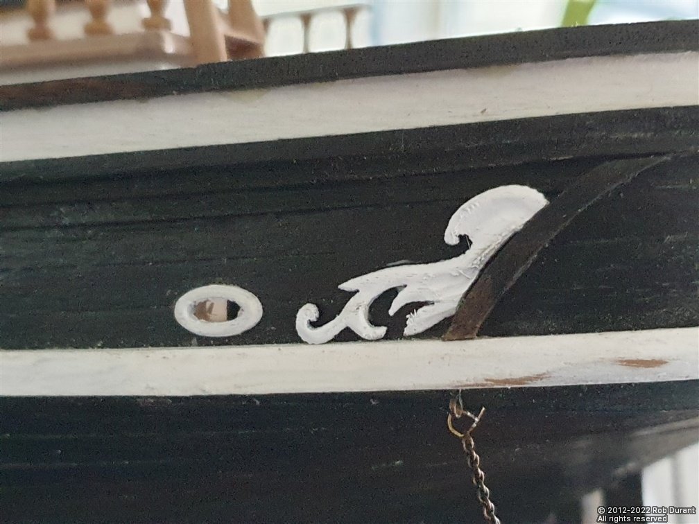
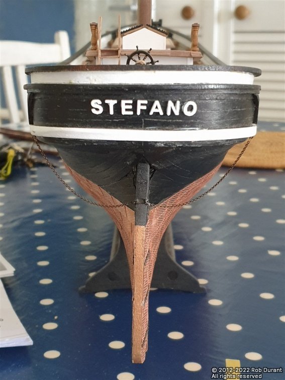
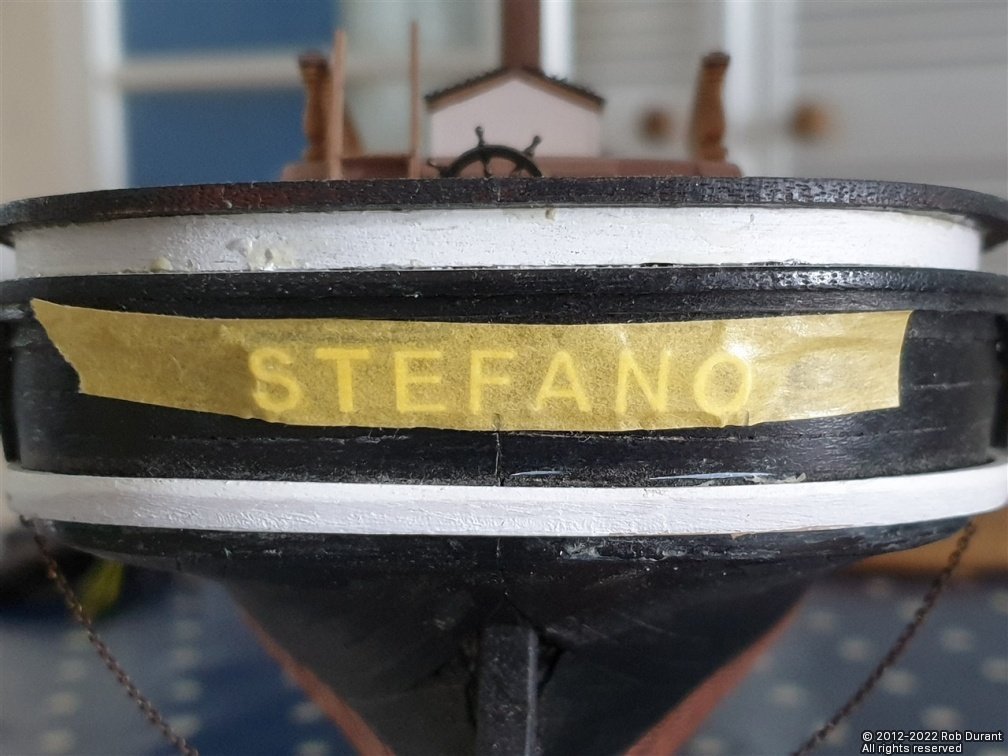
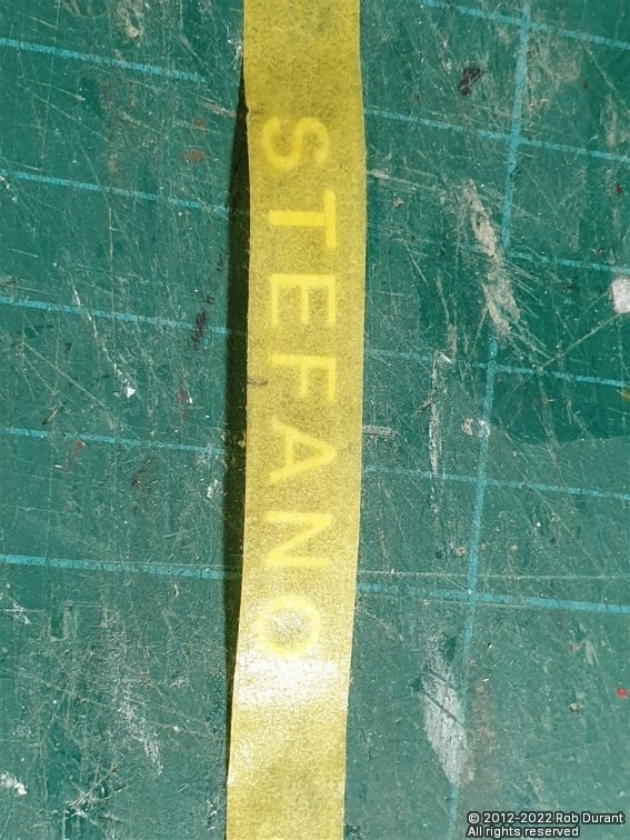
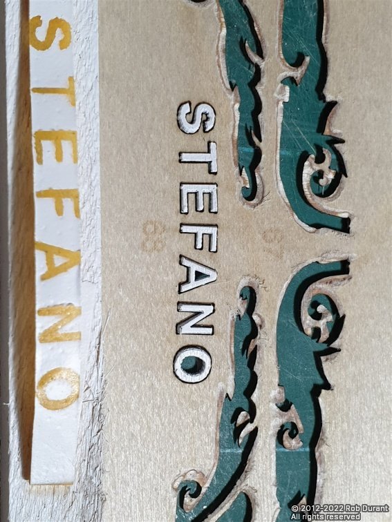
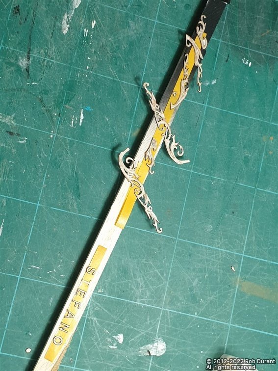
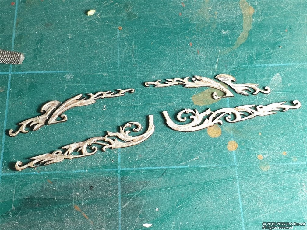
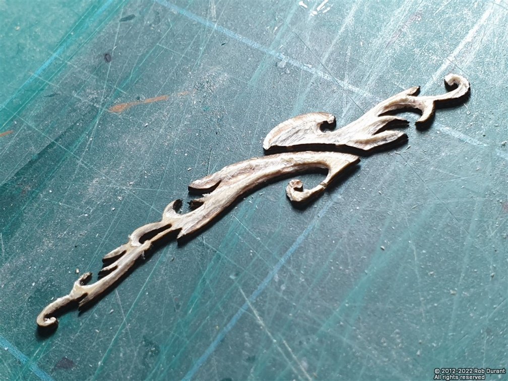
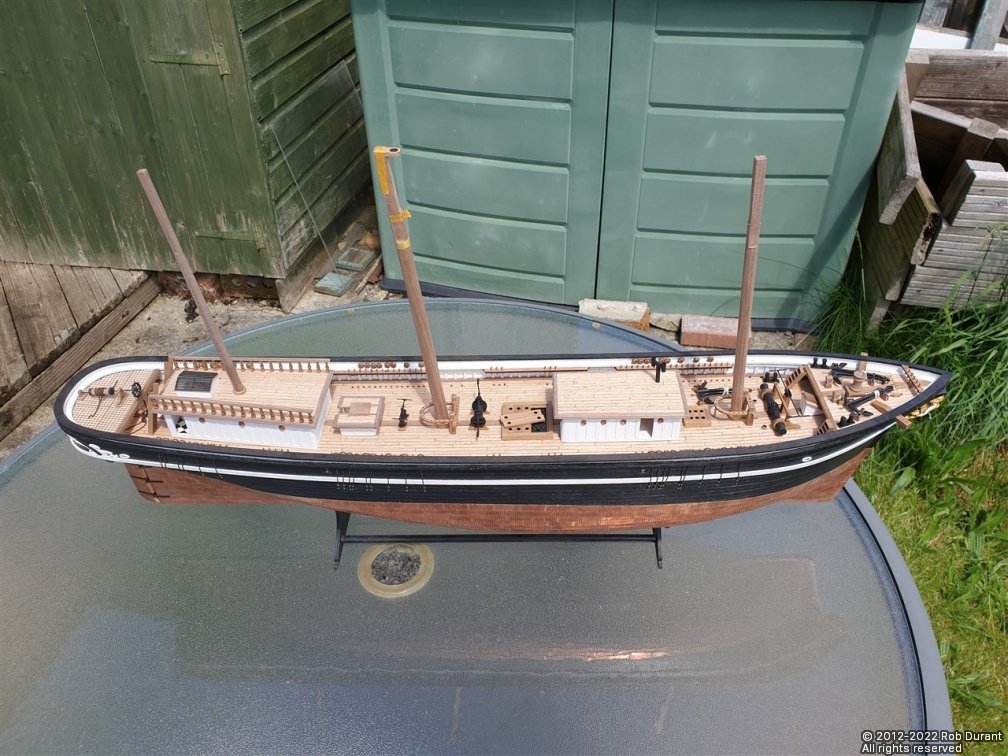
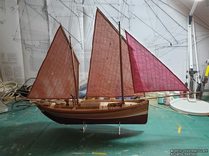
Hi all, Thank you for the likes. I've been doing more work on the deck furniture, and the hull decoration today... one of those days when you can really see the results of the work you've put in, which is always pleasing! 1. The companionway under the forepeak. This was built from styrene, to match the other deck houses, although being so small, I sanded in small rounded edges on the corners instead of using the larger 4mm corner styrene section. The roof was created using veneer as the false base, with beech decking, as per the deck and other deck houses, and 2x1.5mm walnut strip round the edges. The hatch was created in the same fashion as the aft companionway, and this one is glued closed, as there's no hole in the deck to simulate below decks. I've had a few attempts at the doors - not sure I'm happy yet, but at some point I need to bite the bullet and put doors in throughout the companionways and deck houses. The rough structure (this door was replaced later). Making the deck... And in situ (dry-fitted)... 2. Mast clamps... (61, 62, 64) These are laser cut. The fore and main mast bases need a slot filing in them to fit over the king plank. They also need the laser char removing and the top shaping. They will also need the inner edges filing to allow them to sit flat even though the mast passing through them is raked. The main mast base is from the 6mm laser cut panel, and will need sanding down by 2mm. 3. Hull decorations... These are made from thin ply, and need (very gently) shaping to give them depth and definition. I used my proxxon engraving set for this. You can see that even with a gentle touch, I managed to snap off the tiny scroll at the bottom. Thankfully, I found it after a quick search and it was a clean break, so it could be reinstated. Detail is shown on the plans, so you can draw the scrolls and details onto the parts before attacking them... For a first attempt, I'm really pleased at how they turned out. Then it was time to spray them. I decided to add the name to the stern at the same time. Once sprayed, the lettering was placed back into the ply holder to space them properly. Masking tape was stuck over the top, and then the letters were lifted out, still attached to the masking tape. Now, this masking tape could be turned over, and carpenter's (Aliphatic) glue could be added to the back, and the whole then placed on the stern. Once placed, the gaps on each side were carefully checked, and after a minute or so, I very gingerly removed the masking tape and used a dressmaking pin to remove the glue that had oozed out in a few places. Now it was time to add the decoration. This was easy enough for the parts in front of the curve at the stern quarter, as these parts sit flat. For the parts aft of these, they wrap around the stern, and so they were steamed over the spout of a boiling kettle, and then clamped very gently round a curve. This imparted the desired curve, and meant the glue doesn't have to hold this surprisngly tough ply to a curve. Instead, they could be glued on with very little pressure required. And here are the results. 4. Pin rails round the fore and main masts. These are deceptive little blighters. They're simple enough to make, but once you come to put the belaying pins in, even though I drilled the holes out really carefully, they split again and again. The rail itself is not ply, so on the curve, the grain crosses the part, and I must have stuck these back together at least five or six times in the process of getting all the belaying pins in. I'm hopeful that now the belaying pins are in place, they're going to add strength, but we'll see. I can well imagine the whole thing going ping half way through rigging - NOT an something I particular want to encounter! Once the glue's had a good chance to dry, I'll have another look at them and see if they're feeling strong enough. All in all, a very productive time! Here's a picture of the whole vessel... More soon Rob
- 285 replies
-
- 12
-
-

-
A hard lesson, perhaps, but I would think definitely the right choice. Having just rigged my model of Lady Isabella with the high quality sails, and given the completed model to my mum for her 70th birthday, the sails were the thing that set the whole model off, gave it a striking silhouette, and made it really stand out. They're beautifully made, and I was very glad I'd paid the extra to have them. It's a big thank you from me for holding to your high standards! I hope your new stock arrives soon. I'm sure any patience required will be well worth it!
-
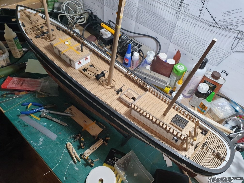
Hi all, I've had a good evening fitting pins to some of the deck furniture, and drilling the holes to position it. None of it's glued down yet, but it all looks much neater, especially as the pin rails round the masts are now positioned. It's really lovely to see the deck starting to look busy, and get something of a feel for what the finished model might look like. The masking tape on the fore cabin is marking out where the stands for the ship's boats will be mounted as and when I get to it. Rob
- 285 replies
-
- 10
-
-
There's often a lot to be said for walking away for a little while and coming back to it. Glad the second coat picked up the greys again. She's looking great!
-
That wooden former is ingenious. And the results speak for themselves. All the waviness is gone. Nice to have some of those finer parts laser cut, too. I was fortunate enough to stumble upon this vessel a few years ago when I visited Amsterdam and the Scheepvaart (National Maritime) museum. She's a very handsome vessel, and seemed very nicely maintained.
- 23 replies
-
- 1
-
-
- card
- World of Paperships
- (and 2 more)
-
Keith, I'm so sorry to hear of your loss. Please be assured of our prayers and thoughts for you and your family at this time. Rob
-
Looks like a good start. Hope you don't mind me following along.
- 23 replies
-
- 1
-
-
- card
- World of Paperships
- (and 2 more)
-
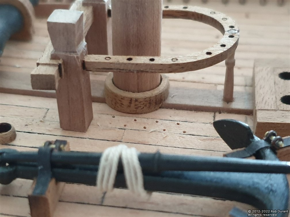
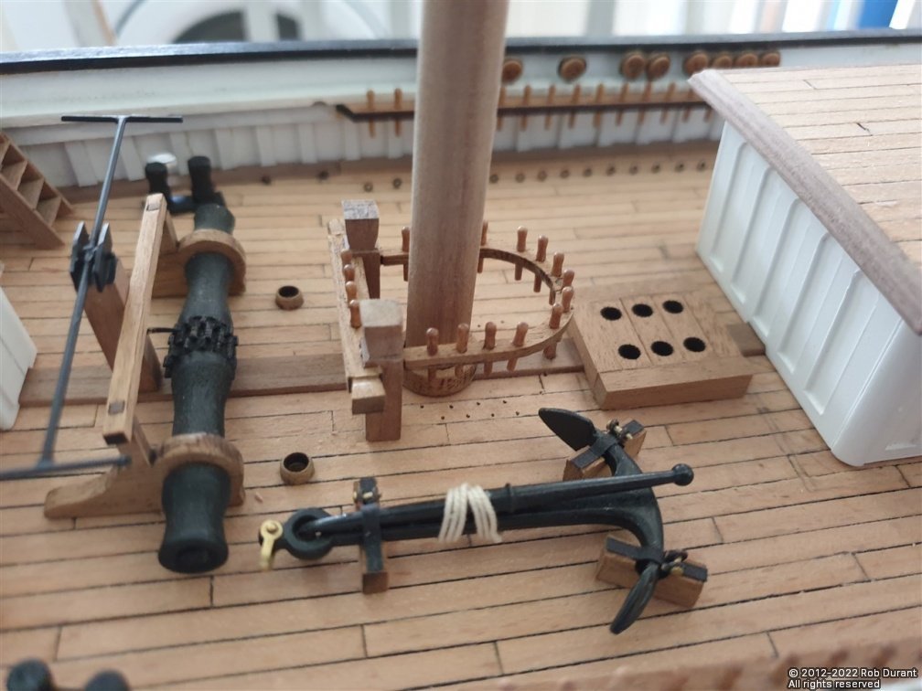
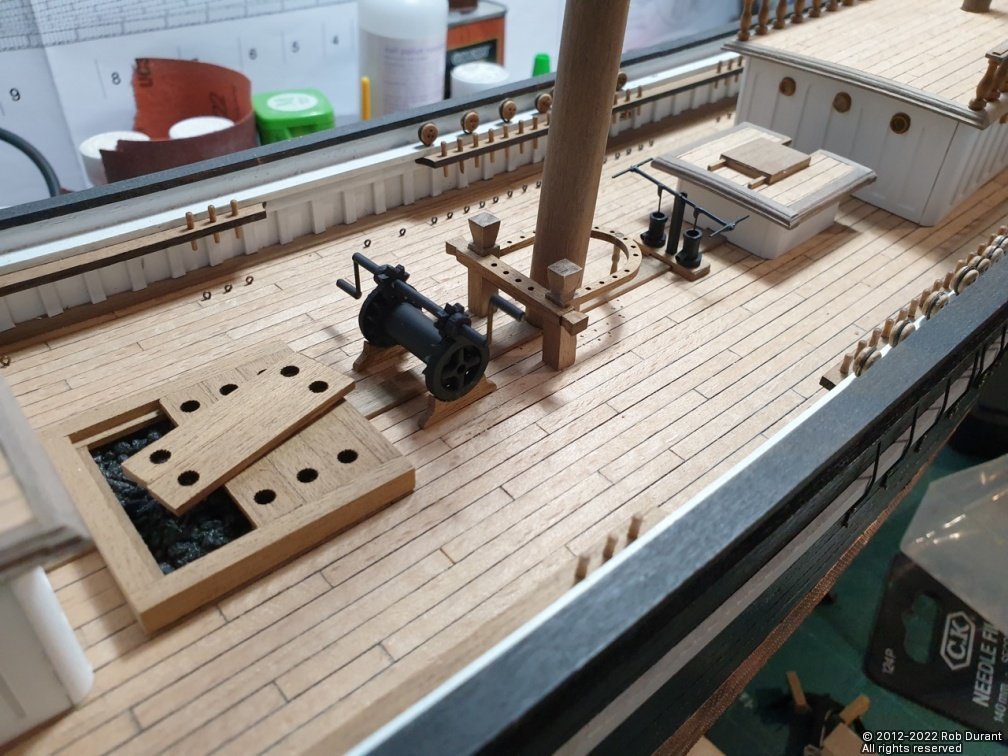
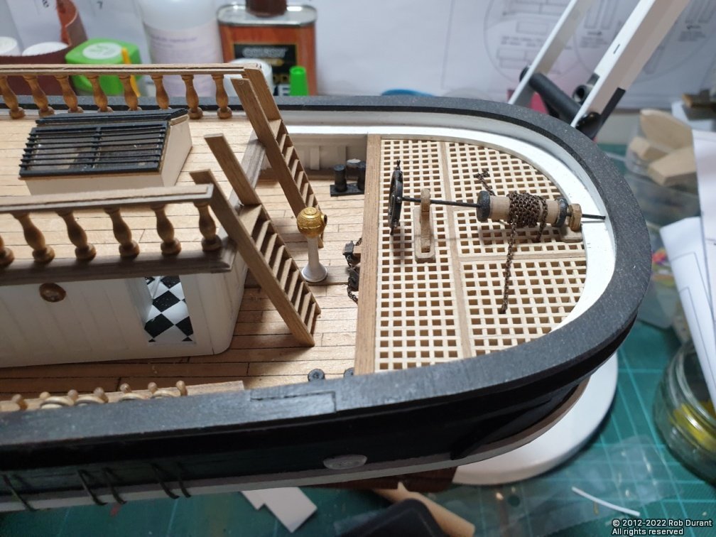
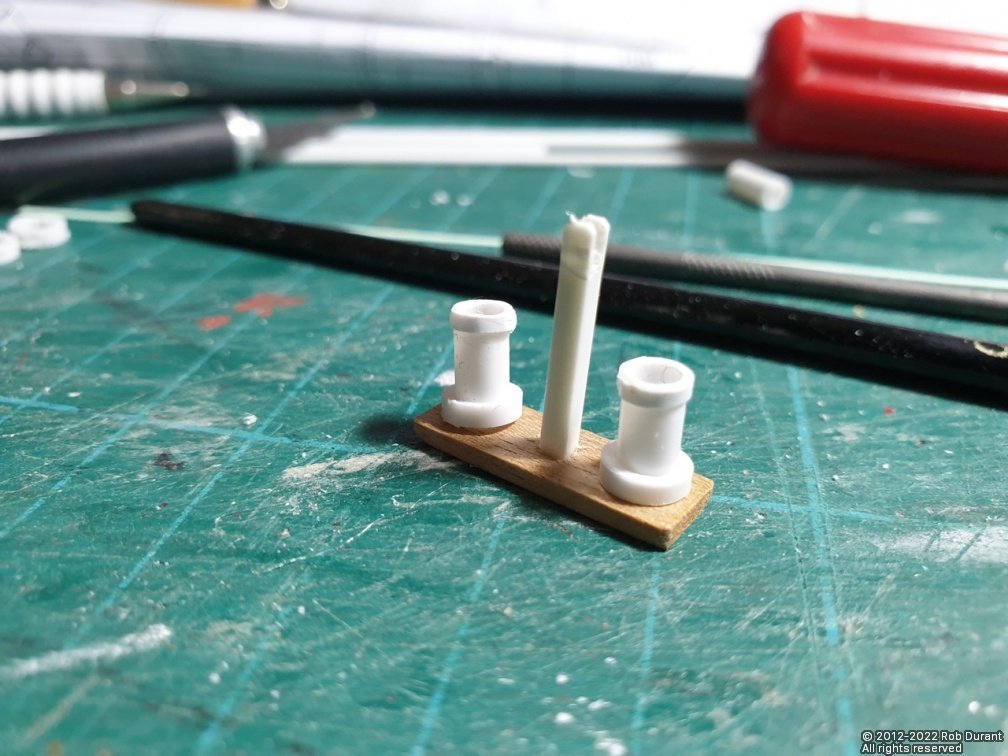
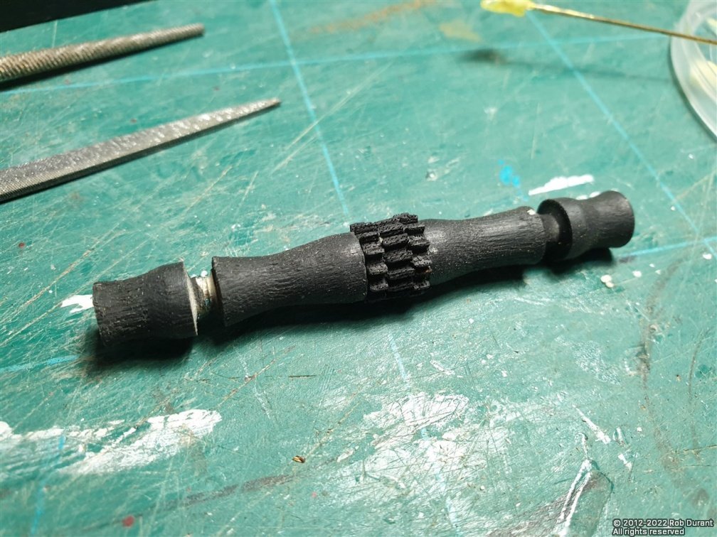
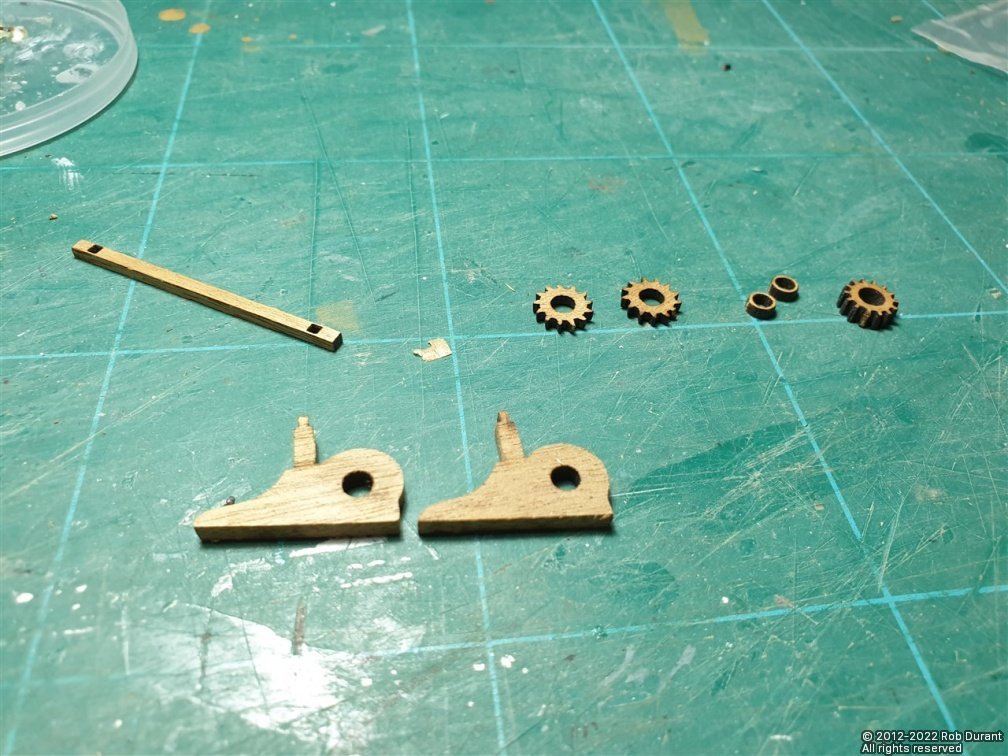
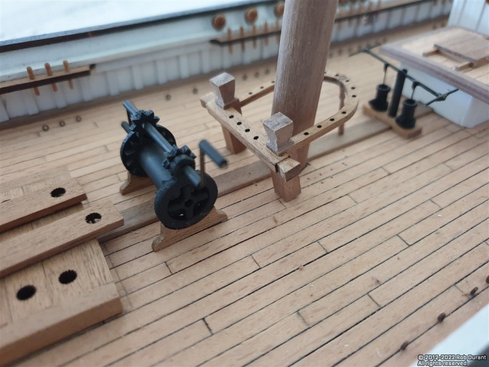
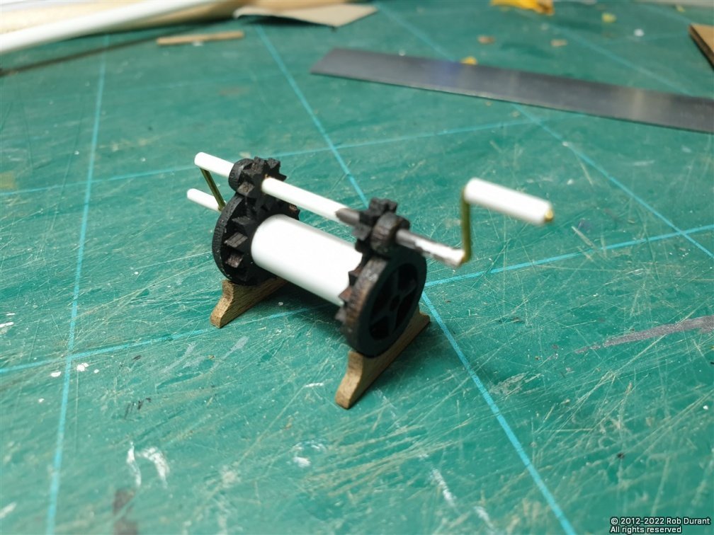
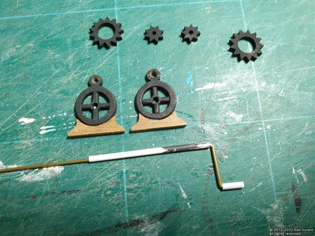
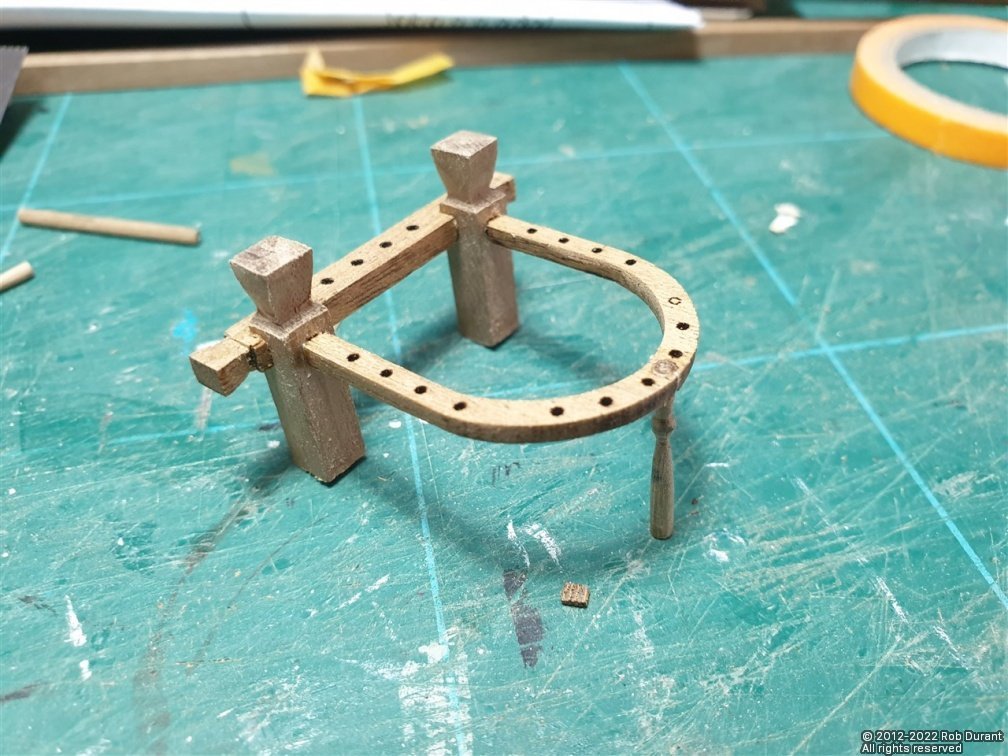
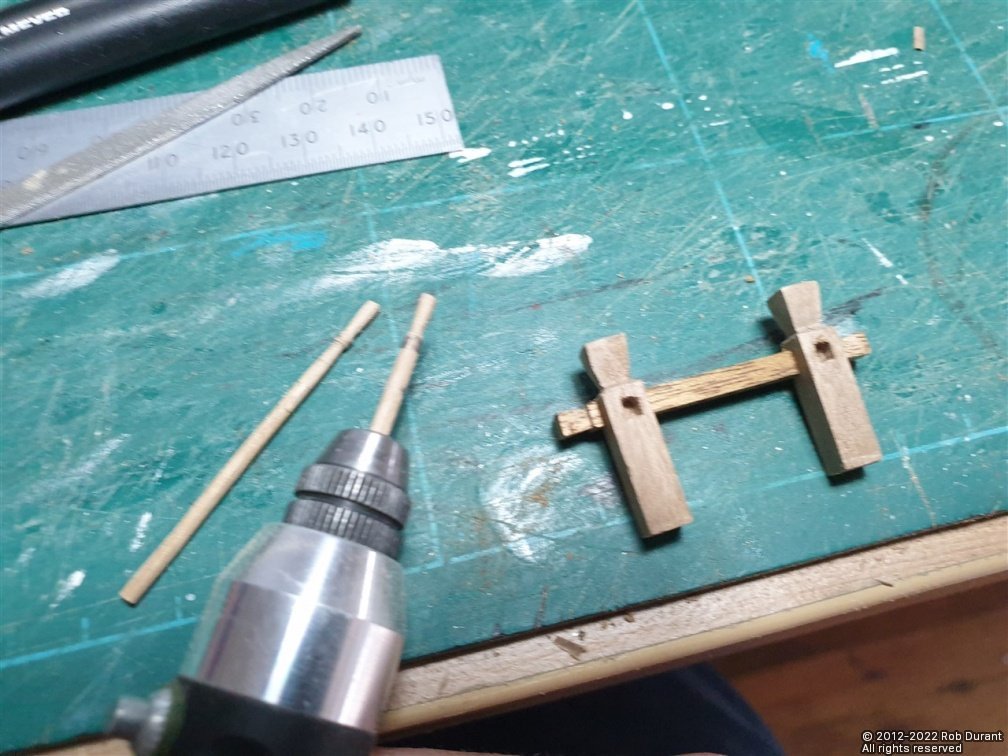
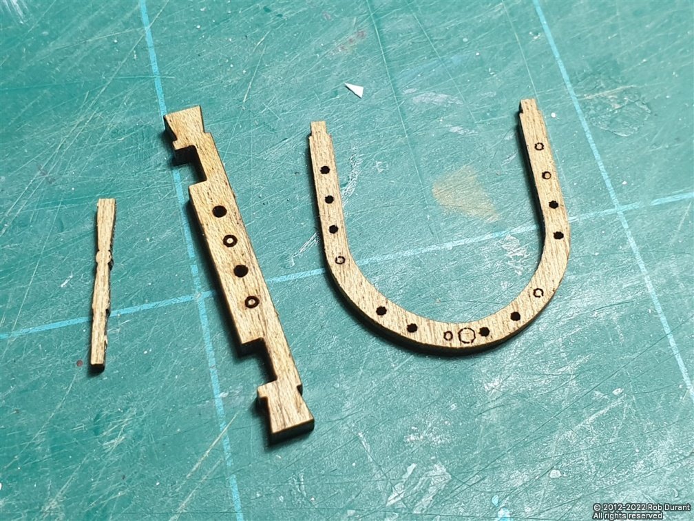
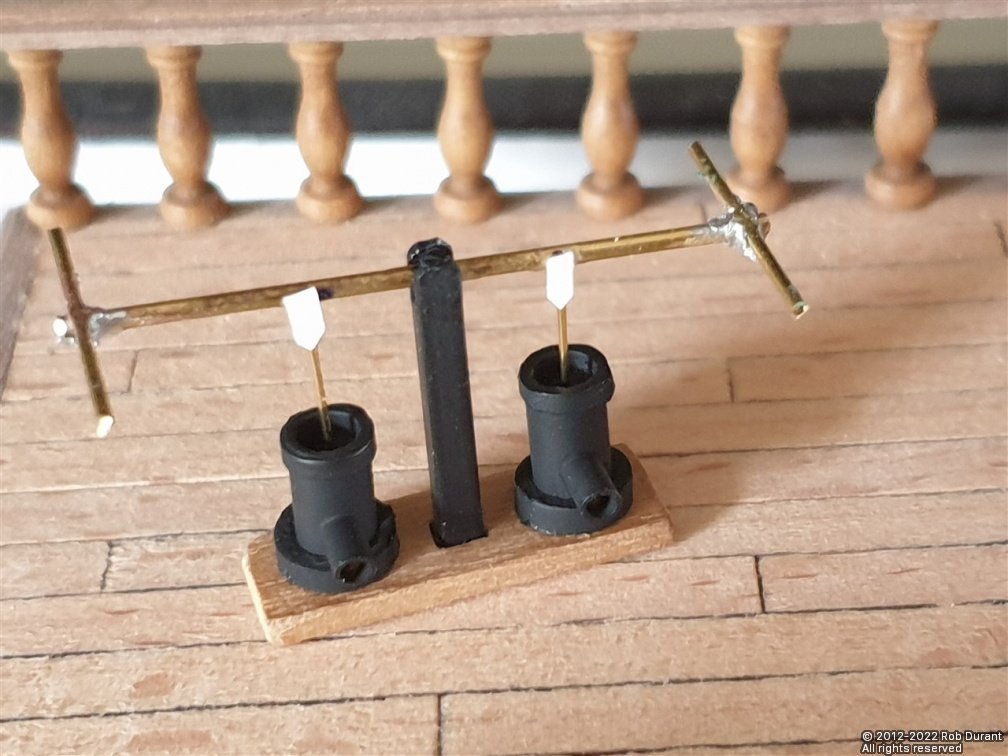
Hi all, Thanks as always for the likes and encouragement. I've been working through more of the deck furniture. In particular the deck pumps, bitts and pin rails round the main and fore masts, and the windlass. In various places I've substituted the suggested dowel for styrene tube, as I find it easier to work with, and I don't have a pillar drill to allow me to easily bore accurate holes through dowel. Pump: I wanted to have at least some sense of the cylinders being hollow and having parts moving up and down in them rather than being solid, so I used styrene tube here, with a larger diameter styrene tube for the rings. The upright was also made out of square section styrene, and the rest from soldered brass, which had not been tidied up at the time of taking the photos. I used small tabs of styrene to simulate the linkages between the cross bar and the vertical rods. In retrospect, I didn't file the gap into the base for the king plank before I assembled this, which meant I had to go back and add more walnut later. Next were the bitts and pin rails to go round the masts. These were made up as per the kit instructions. The pin rails were fiddly to sand, but care and patience won the day. The only part I replaced was the turned upright, which is provided as a laser cut part, as shown in the first photo below, but I turned from 3mm walnut dowel instead, as it was easier. The smaller uprights were turned in my proxxon drill with small files (the lathe would have been complete overkill) And then it was on to the windlass... These parts are lasercut. Again, I substituted styrene tube for dowel here. Finally, I've been working on the other windlass, which remains unfinished to date... Again the parts are partly laser cut, but the main drums are all fashioned from 8mm dowel. I decided to turn these in one go on the lathe, so I could be confident they would all fit nicely. I'm pleased with how this went. So this is where I've got to so far. Close ups are a bear, but it looks pretty nice from a normal distance. By turning the gaps to be the right width and diameter, I can simply cut them in the middle, and they pop into the 4mm holes in the laser cut parts. A little fettling was required, but it means it should all line up nicely in the end. Right - that's it for now. Happy building, all Rob
-
Seeing those motors brought back very fond memories of building one of Deans' destroyers - HMS Grenville - when I was a teenager... I decided that two Kyte motors seemed a bit wimpy, and installed the larger Kondor motors (more like the 58x series than 38x). For a 3' 9" model with a beam of about 4.5", that model would go from 0-60 like a Ferrari, and I remain convinced it would have gone straight up the side of a lamppost if it had water flowing down it! I absolutely loved it! Useful when you see another ship heading straight for midships, too! One of the many experiences that got me hooked on model ships for life. I look forward to seeing the build log as an when you get to it
-
Those are very nice touches that will help the builder to enjoy the process and get a great result. Excellent stuff!
-
Well, there's been a bit of a gap due to real life quite rightly intervening, but I've had the opportunity to begin planking one of the boats with 0.5x2mm walnut, and to turn the mizzen mast (it just looked odd with fore and main dry-fitted, but not mizzen!). In theory these ship's boats will now be planked again... I'm sure that will add strength, but I wonder whether it will make them look over-scale? One possibility (since I really struggle making these boats) is that I'll put canvas tops over them, which will remove the need to make the insides look pretty, and allow me to leave the balsa blocks inside. I could even do that having removed a good part of the balsa and seen just how strong it actually is, or indeed, having double-planked it. Lots to ponder! Just a little progress for this update, but hopefully lots more, soon . Thanks as always for the likes.
- 285 replies
-
- 11
-
-
They're very vulnerable aren't they... I've been trying to work out how to add them to my model at just the right moment without breaking them off. The bits of paper to make them more visible are ingenious, though. You're doing a beautiful job of this kit.
- 481 replies
-
- 2
-
-
- Cutty Sark
- Revell
- (and 2 more)
-
What a fascinating vessel, and very interesting conversation - I wish you all the best in this build (and her sister-ship in a different scale), and I hope you don't mind if I follow along with both builds.
-
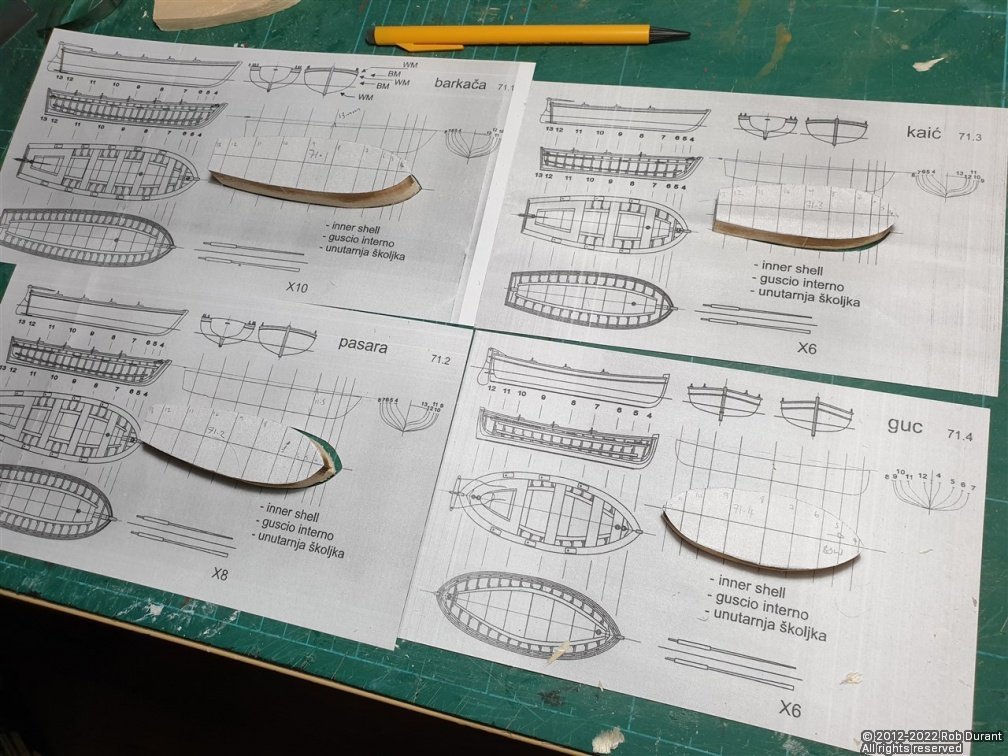
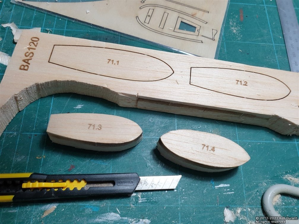
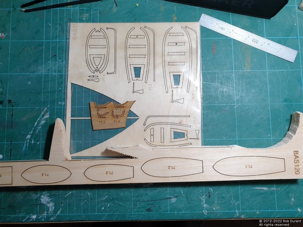
A full complement of molds... These will need to be shaped on top as well, as the first planks laid are the rubbing strip. It's a fascinating exercise going through these four different craft one by one and seeing the subtly different shapes of the hulls.
-
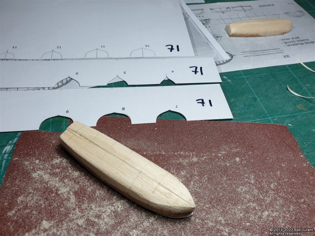
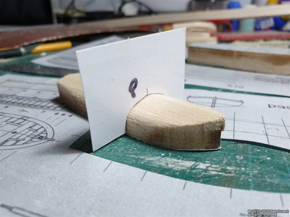
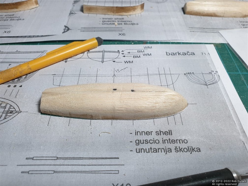
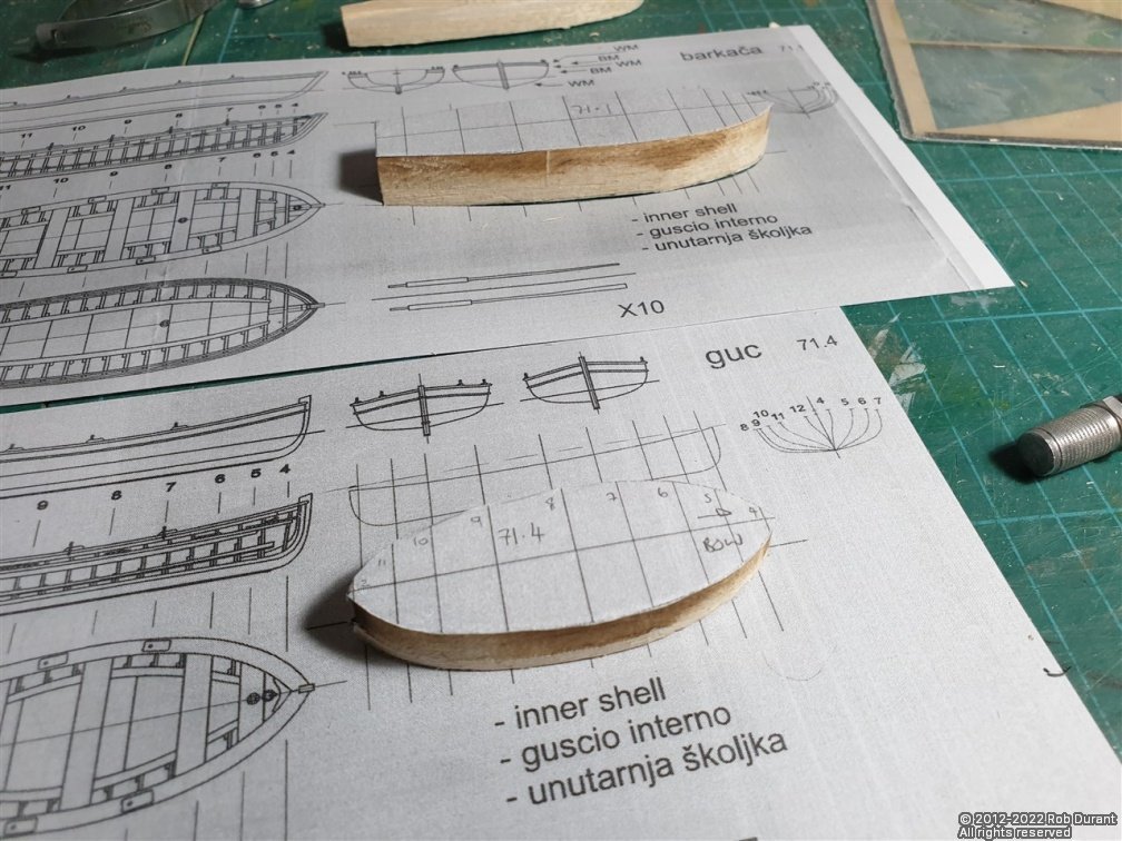
Hi all, Another little update on the boats. I've used CAD to create templates for the profiles of the ship's boats at each cross-section. These are then printed, laminated, and cut out. They can then be used to check the shape of the plug at each frame. So far I've done the moulds for 71.1 and 71.2. I'm pleased with how these are going so far. I've also taken delivery of the 0.5x2mm walnut strip for planking them. First the positions are marked on the plug Then the biggest template (#8) is used to reduce the length of the plug to that dimension... The other templates are numbered from bow to stern, and can now be used to reduce the plug smoothly down to those stations... Et voila! For a first and second attempt, I'm really pleased. 71.3 and 71.4 to shape, and then we'll be thinking about how to stop the boat sticking onto the plug as I plank it. I also want to replace the keel parts in the kit as they're plywood, and completely the wrong colour. If I can, I'd like these boats to end up as natural walnut. Time will tell whether I do a nice enough job of it. More soon Rob
-
Picture Orientation.
robdurant replied to stuglo's topic in How to use the MSW forum - **NO MODELING CONTENT**
Hi Stugio... You could try looking here: I've put a video on there that describes (and shows) why these things often happen. If you use Windows, then you can get round the issue using the free application I've programmed. If you're using Mac or a phone, then you'll need to find something that does the same thing: it hard-codes the orientation of the photo instead of using a "meta-tag" hidden inside the image file, which your gallery app on your phone will read, but the web browser on your phone won't. It's frustrating, but it can be worked around. Simply turning the photos on your phone updates the meta-data, but doesn't rewrite the photo (for good reason! it takes a lot less processing power), but that doesn't fix it for your internet browser, as you've discovered. If any of what I've said doesn't make sense, do ask. I'll do my best to explain more clearly. -
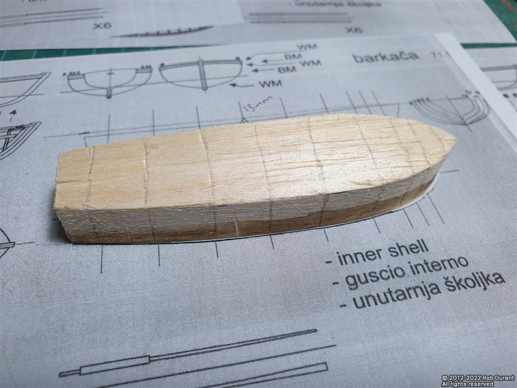
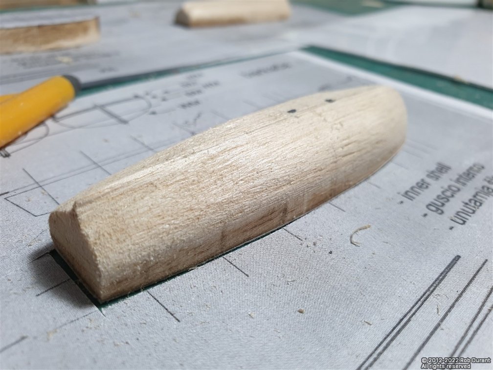
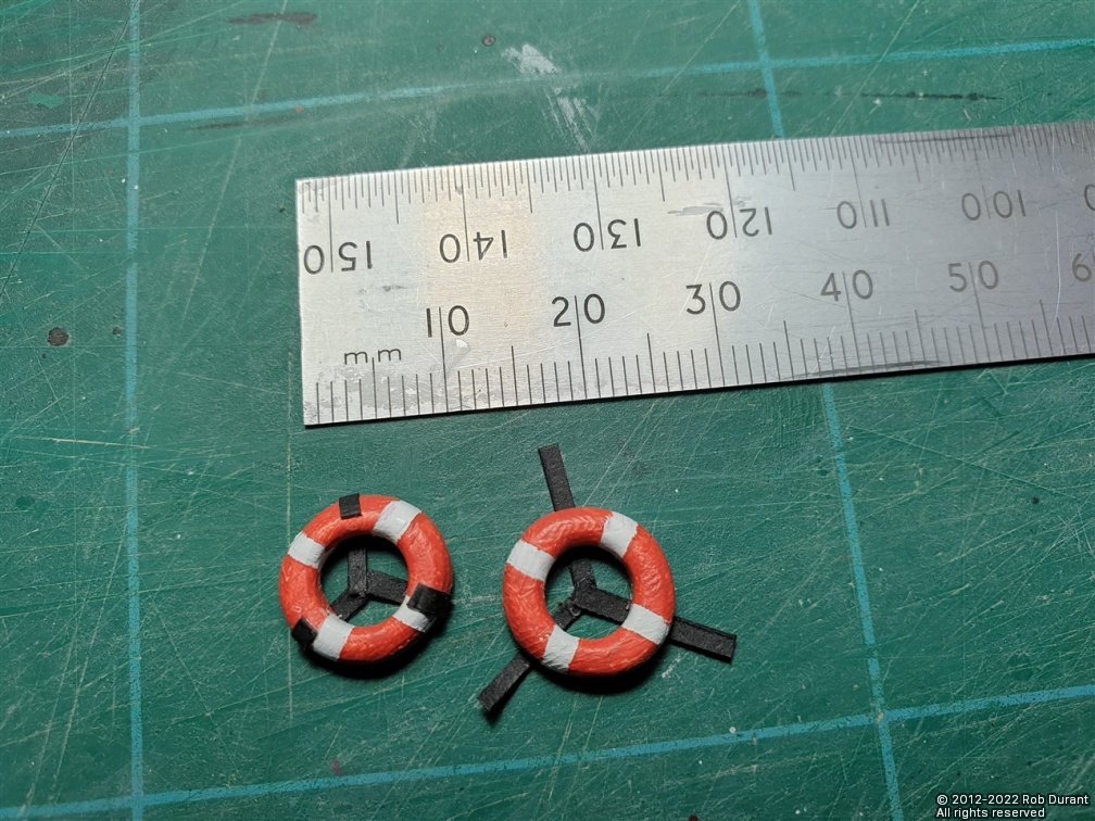
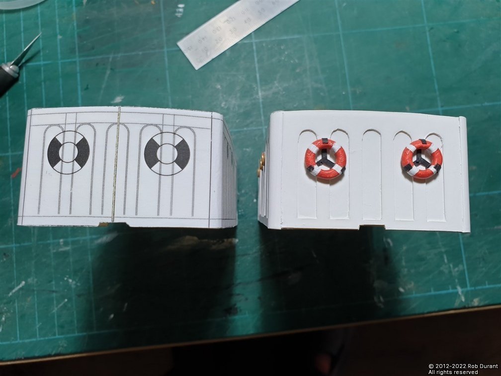
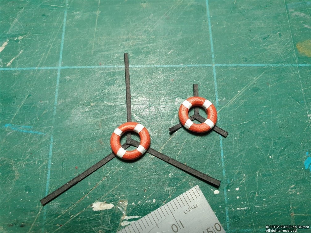
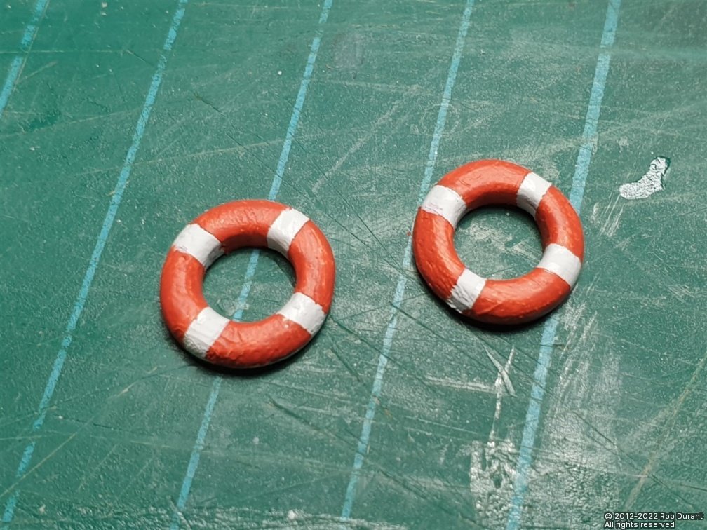
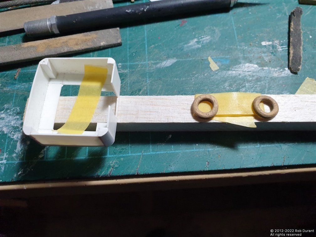
Hi all, I've made up the lifebelts for the stern-end of the fore deckhouse. These are laser cut "donuts" of 3mm walnut that I shaped by temporarily gluing them on to styrene tube which I could then use in a drill to turn them and file them into shape. Once shaped on the outside, they were taken off the tube and shaped on the inside. They were then sprayed with white primer, then masked with thin strips of tamiya masking tape. The mounting frame was made of black card, and glued straight onto the lifebelt... The whole assembly was then superglued onto the deckhouse. Here it is compared to the original mockup... Next I moved on to start the ship's boats... It seems to me that you need to make these at this point because the boats stands should be fitted to the deckhouse roof and need to be shaped to the boats before fitting. The boats are made over balsa moulds... Here are all the components provided... The first task is to cut the mould balsa out of the sheet provided. The outline is lasercut, so that's nice and simple. I've made scans of the plans to stick on the top of the mould so I have a good idea of where the bulkheads ought to sit, and have cut the moulds to overall height. All in all a productive few days. Reading the instructions it suggests that 0.5x2mm and 0.5x3mm walnut strip should be cut from 0.5x4mm walnut in order to plank the boats... I was fairly convinced that that way lay madness, so I've ordered a quantity of both 10x0.5mm and 2x0.5mm walnut from Cornwall Model Boats to give me both planking strips that are nice and flexible (and hopefully compliant!), and some wider strip for curved planks or the frames that go in the boats, which are also to be cut out specifically (and sadly not provided as laser cut components). I'll update you as I go. Rob
-
My experiences with using several irons
robdurant replied to modeller_masa's topic in Modeling tools and Workshop Equipment
I don't think a minimum of 180C should be a problem... When I'm bending ribs for a violin, I can use the same heat setting (~250C) without water, and the wood won't bend, it'll just burn the wood within a few second, and if forced it will snap. BUT if I use the same temperature, but first run a wet finger along the wood I want to bend before I apply the heat on the side where it will be contacting the bending iron, the steam does the work, and as long as I only keep it in contact for perhaps ten seconds, then hold the wood in shape as I remove it and it cools, the bend takes, and there are no marks left on the wood (and the wood is pretty much dry because of the heat, so no waiting to use it... It's a skill that you get a feel for, for sure, but higher temperatures and some moisture yield quite amazing results... Obviously you need to use your common sense and be careful with water around electrical equipment, but I wouldn't recommend trying to bend wood without at least a little moisture present. The advice I try to follow is that you'll know it's hot enough (at least for maple) when dropping a small drop of water onto the heating surface causes it to bounce straight back off rather than sit there and sizzle.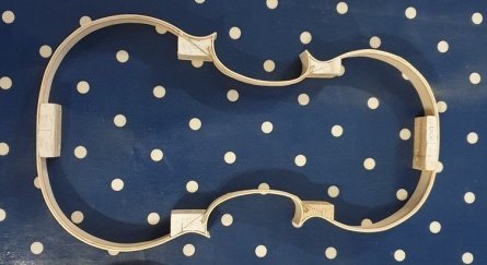
-
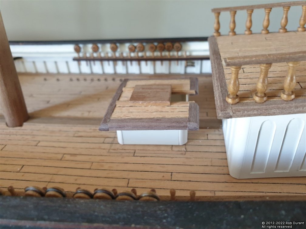
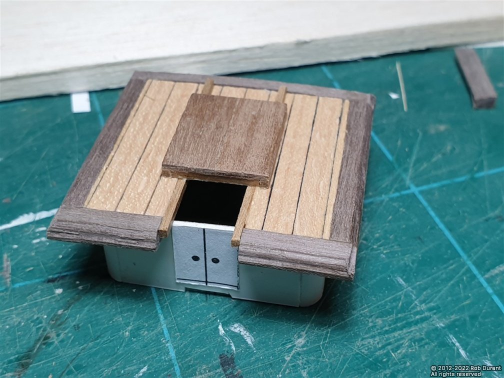
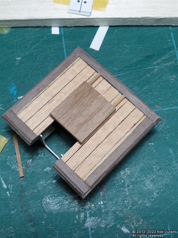
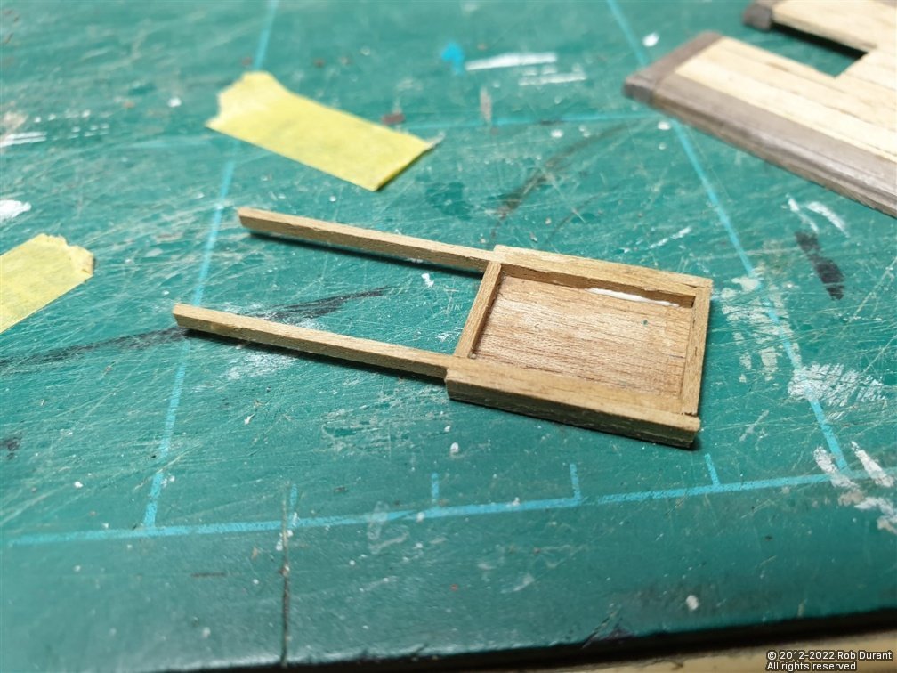
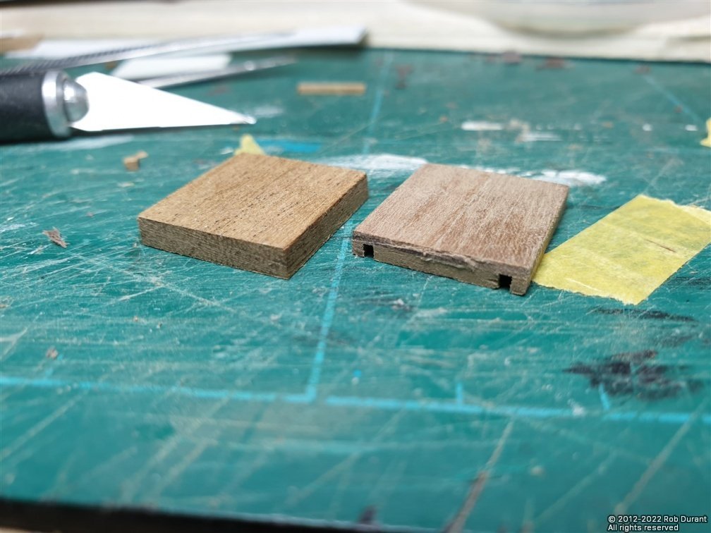
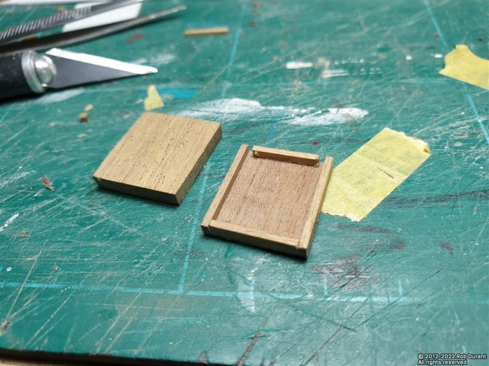
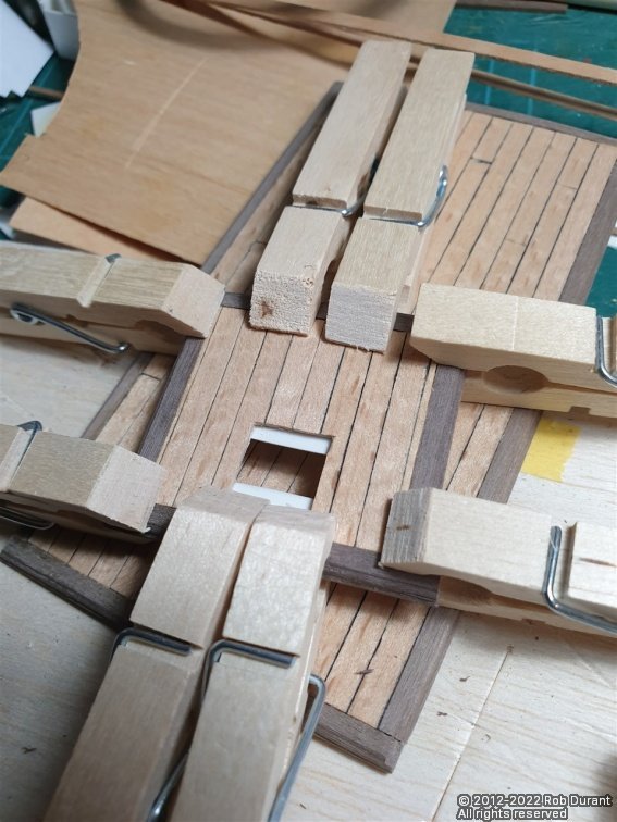
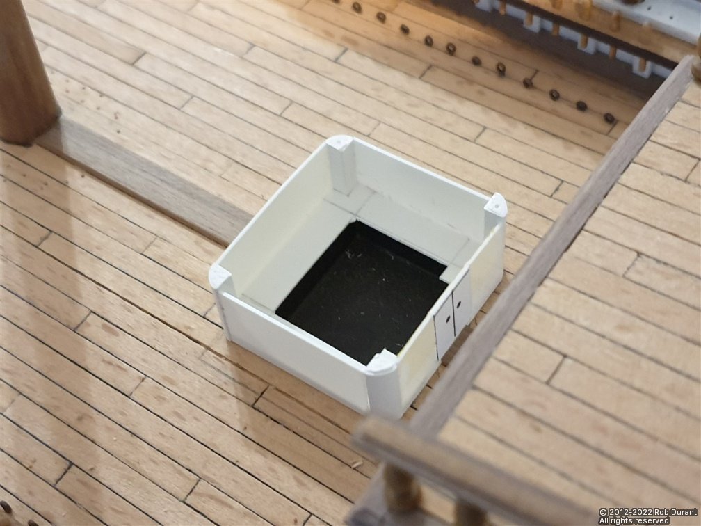
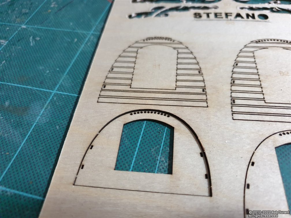
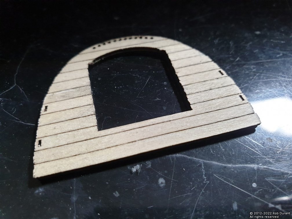
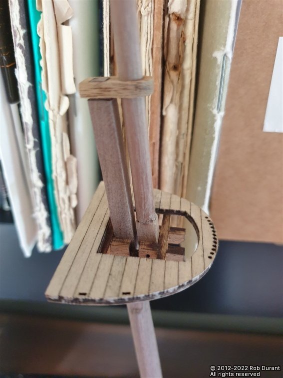
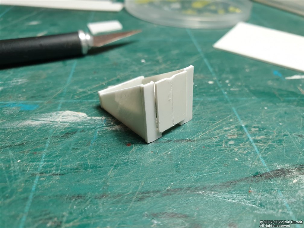
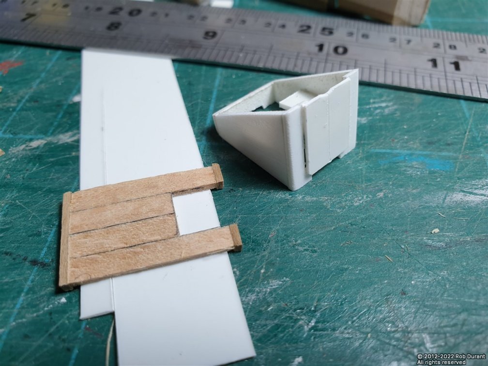
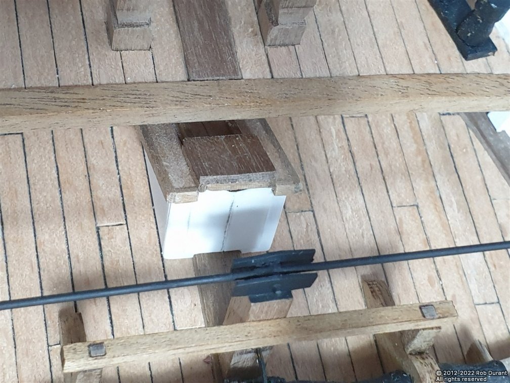
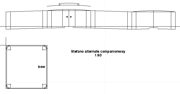
A little more progress. I've been working on the companionway... I had mentioned I think, previously, that I thought this was going underneath the foredeck... it doesn't. That's a completely different companionway, shaped like the quarter of a circle. This companionway goes just in front of the aft deckhouse, and having realised that (thankfully before I got too far along) the plans were redrawn in cad with the angles updated to achieve vertical front and back, and construction began in earnest using the same materials as the deckhouses (styrene for the main box, and wood for the roof). Here's the plan... (Download it as a PDF here: CompanionWay.20220329.pdf) The line running through the middle is the bottom extent of the former, so that it won't strike the king plank. If you want to have the doors to the companionway open, as I did, you will need to trim out the centre of the former as required. And the structure itself... (notice that the first photo is of the structure before I realised my mistake, so the sides are at far too steep an angle (because the deck at the bow is much steeper than at the correct point aft). The following photos are of the correct version as above. As always the plans are fixed to the styrene using pritt-stick... this gives just enough sticking power to keep the paper in place as it's cut out, but simply pulls off and any excess can easily be removed with a damp cloth. The styrene structure complete and in place over the deck, where the cutout was prepared. The aim is to give the impression of the drop-away that someone would climb down into through the companionway. I may make a dummy ladder top to sit in here, too. Progress on the roof - which was made the same way as the others... Then it was on to the hatch. In the kit this is supplied as a 4mm solid block. It looked a little heavy and monolithic to me, so I made a replacement out of walnut 1.5x4mm planks, and used 1x1.5mm strip round the bottom to make space for the runners (which were also 1x1.5mm strip). Here are the two parts for comparison... With the runners... And in place... I've begun to line the inside of the companionway... The doors are already cut out, and will be open eventually. And a final really bad photo of the part in situ on deck... (dry-fitted) I'll try and get a better photo later today There's no paint on the structure yet, and it'll need some tidying up, but I'm happy with how it's come out. You can see where I'm going to have to remove some markings from the deck, where I accidentally marked out the extent of the roof, not the structure itself. Thankfully it's only pencil. Rob
.jpg.1b5c2aa6b8f3e0f0a5a90e870d6a7bde.jpg)