scrubbyj427
-
Posts
1,729 -
Joined
-
Last visited
Content Type
Profiles
Forums
Gallery
Events
Everything posted by scrubbyj427
-
 Nicely done! Onward to the fun stuff!
 -
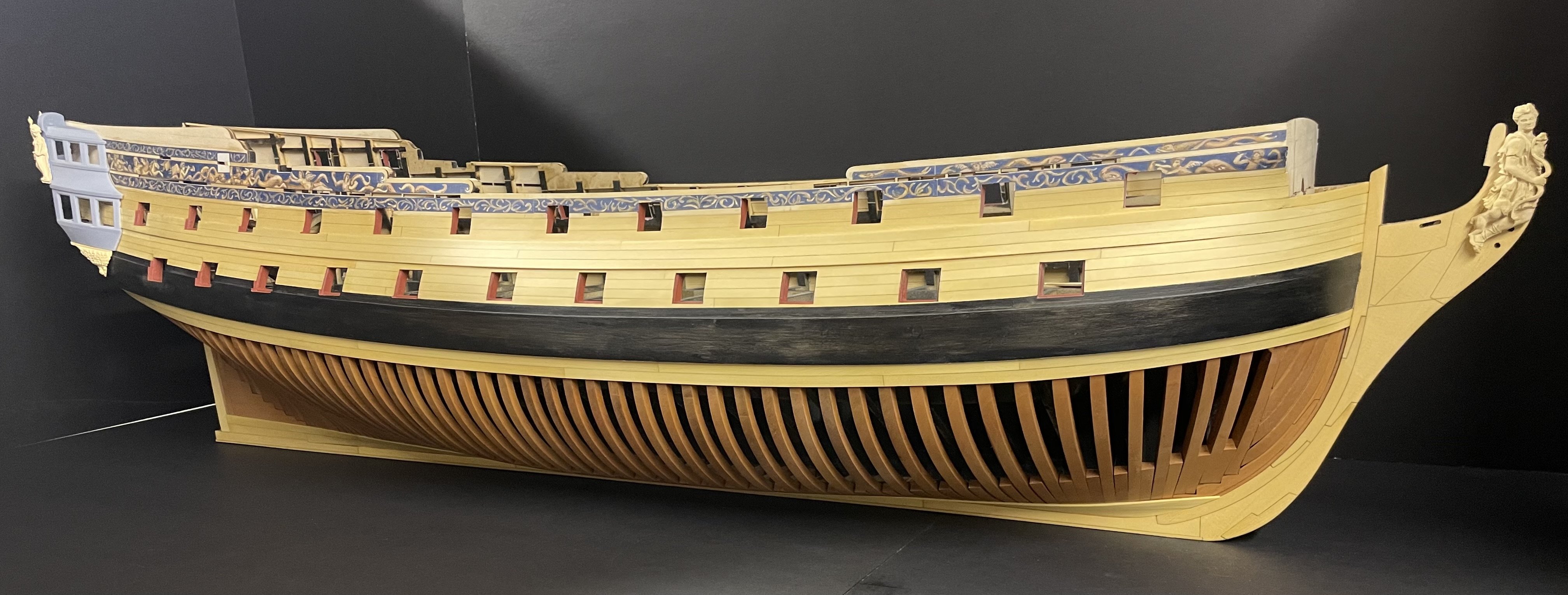
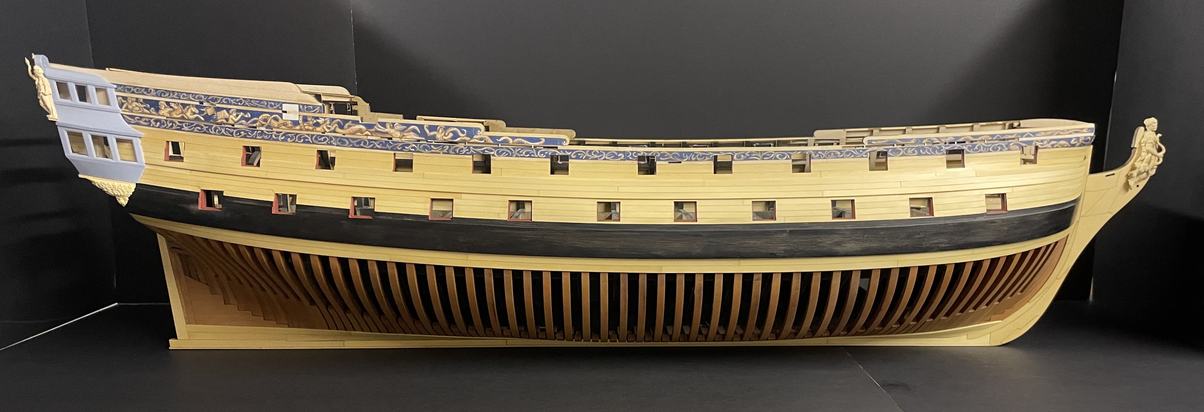
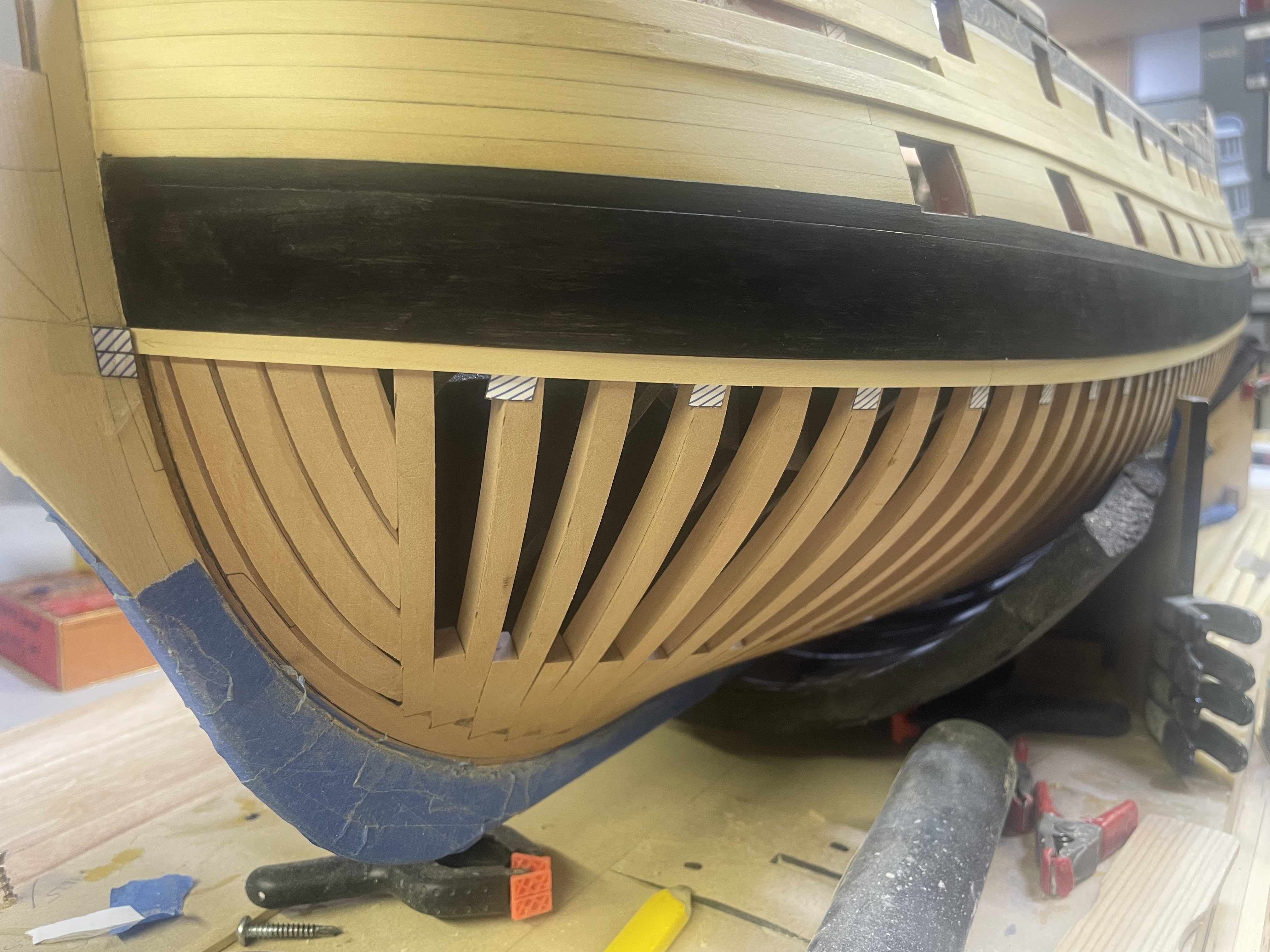
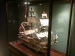
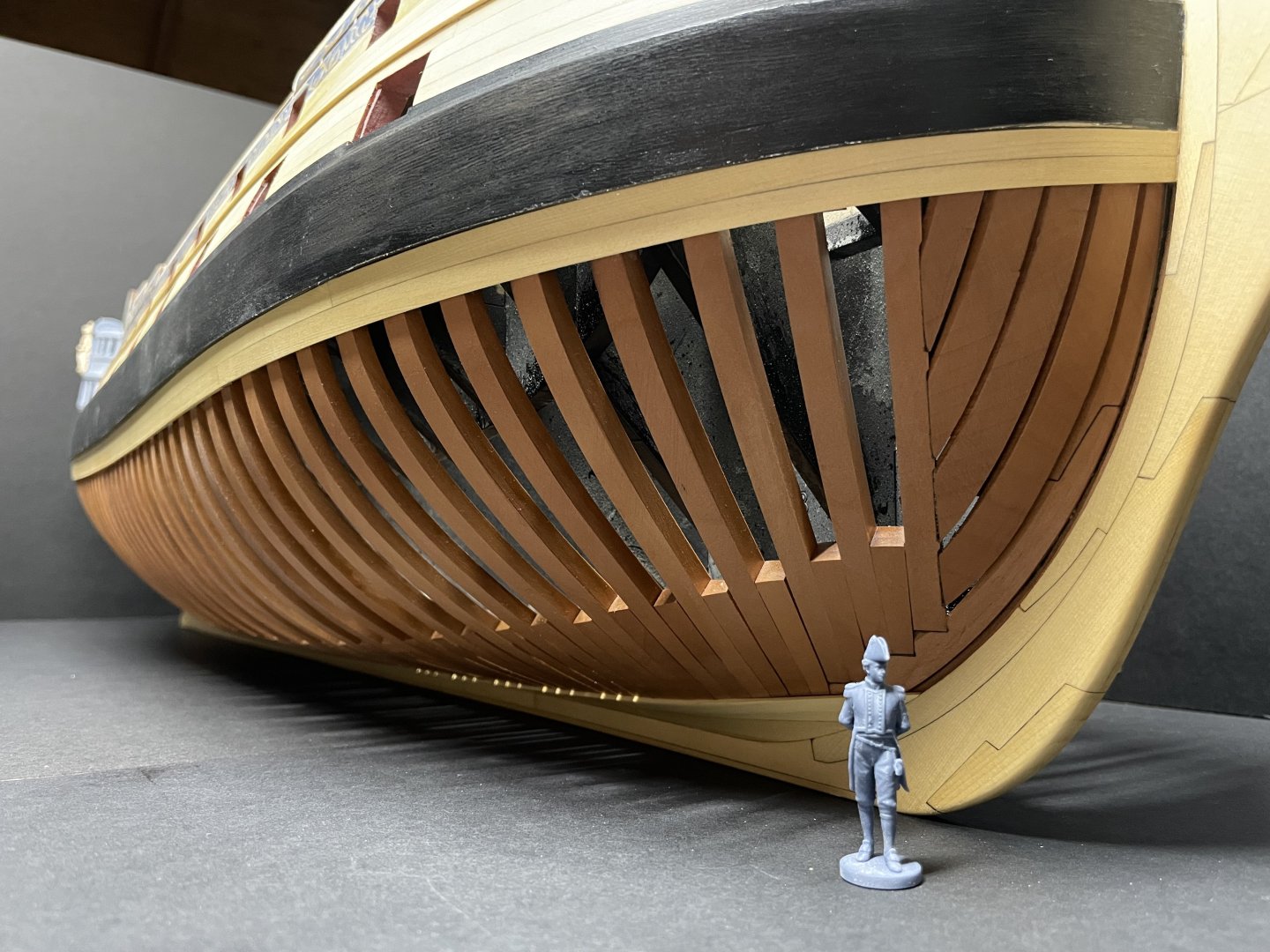
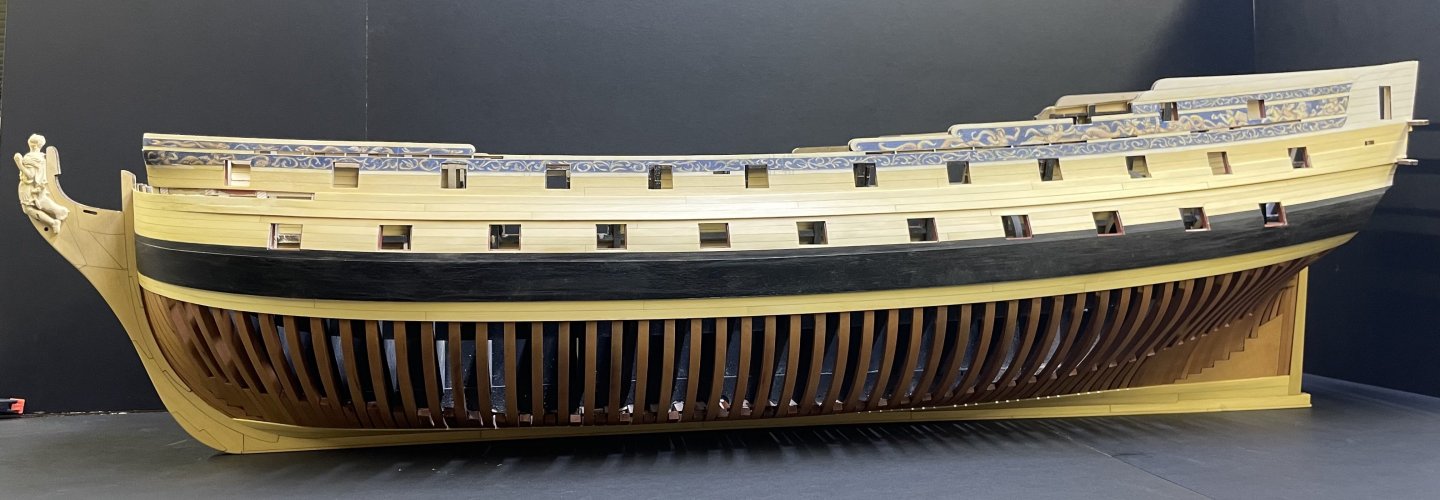
Almost done with Chapter 2, here’s where the model is at this point, warts and all!. A few more things to wrap up and I will begin fairing the inside and getting ready for chapter 3.


- 425 replies
-
- 25
-

-

-
Thank you Thukydides. There’s more coming soon!
-
Thank you Steve. I’m producing instructions to go along with the kit that a more detailed than my poorly assembled build log lol. Cutting two kits now. More to follow.
-
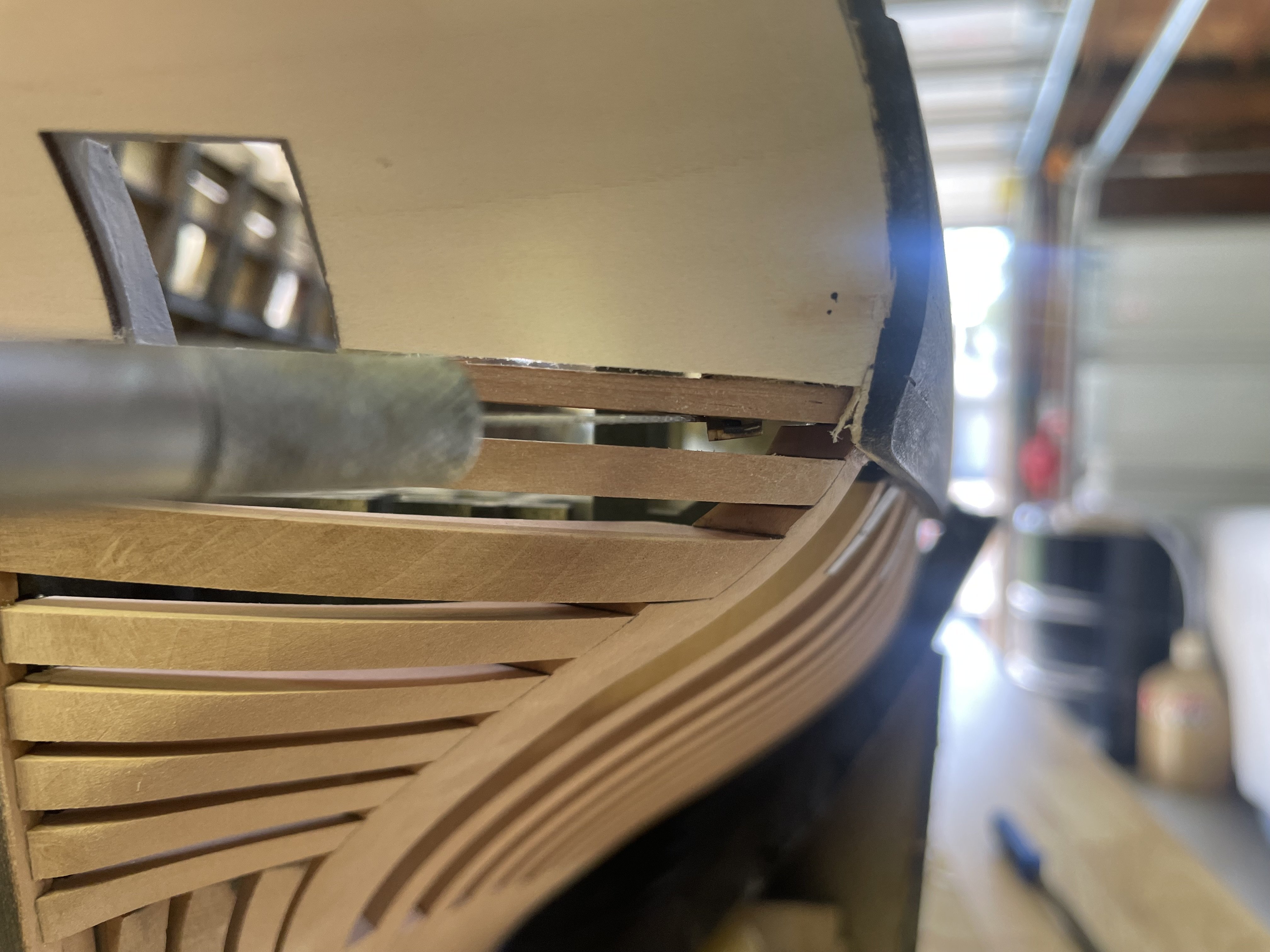
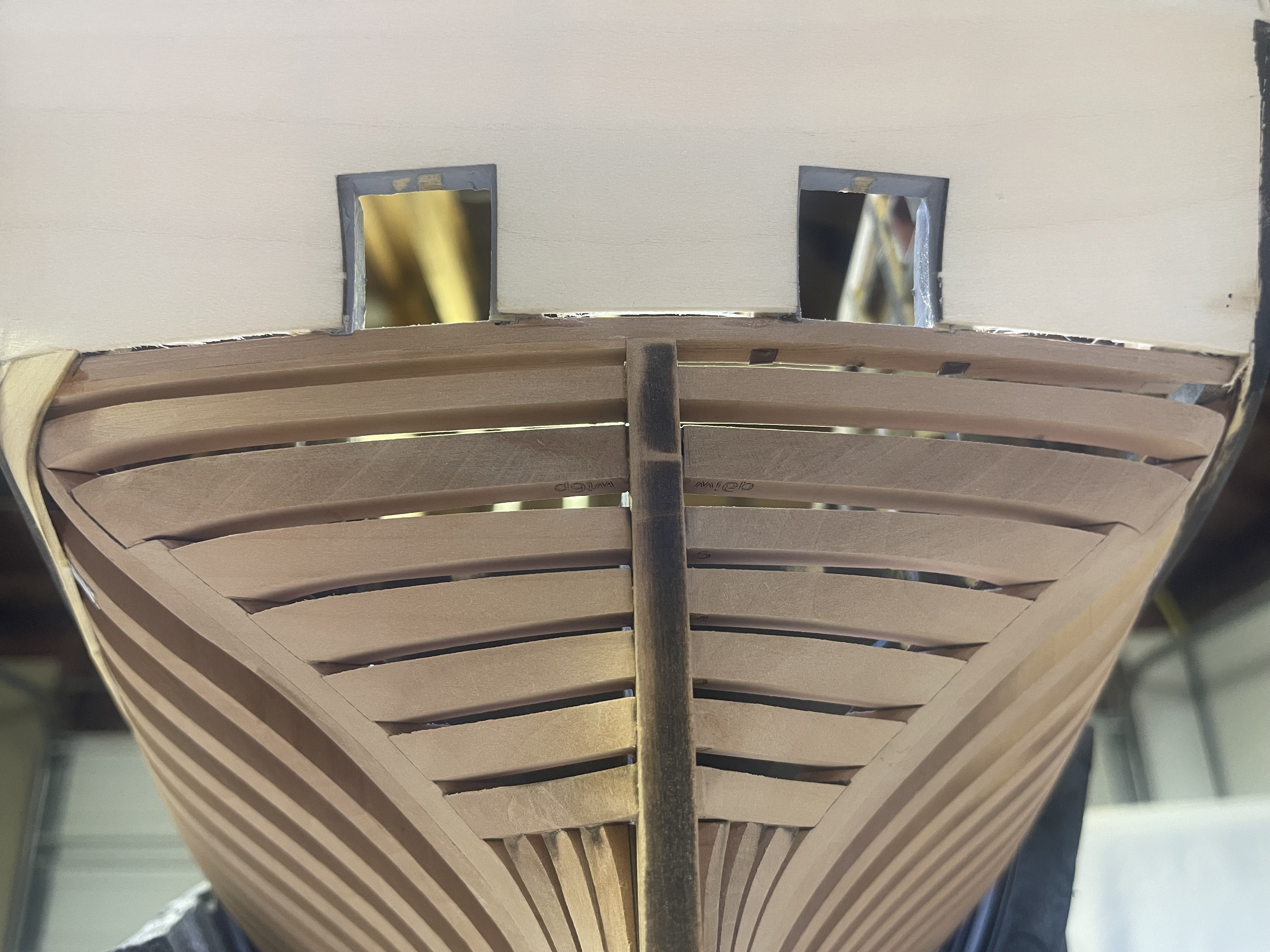
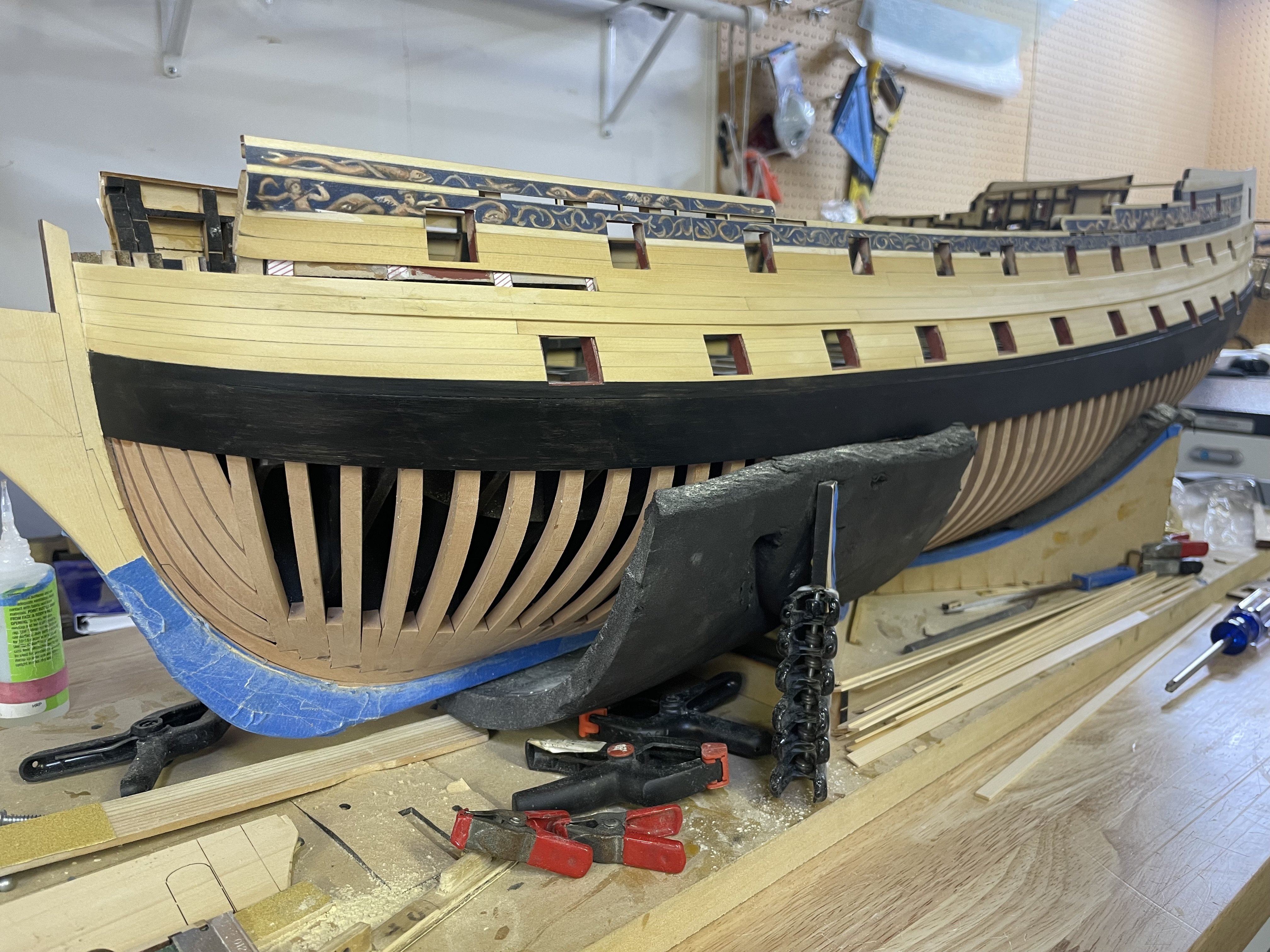
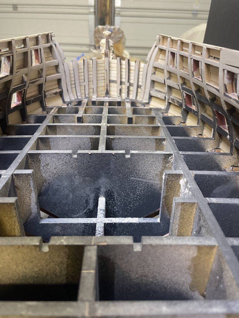
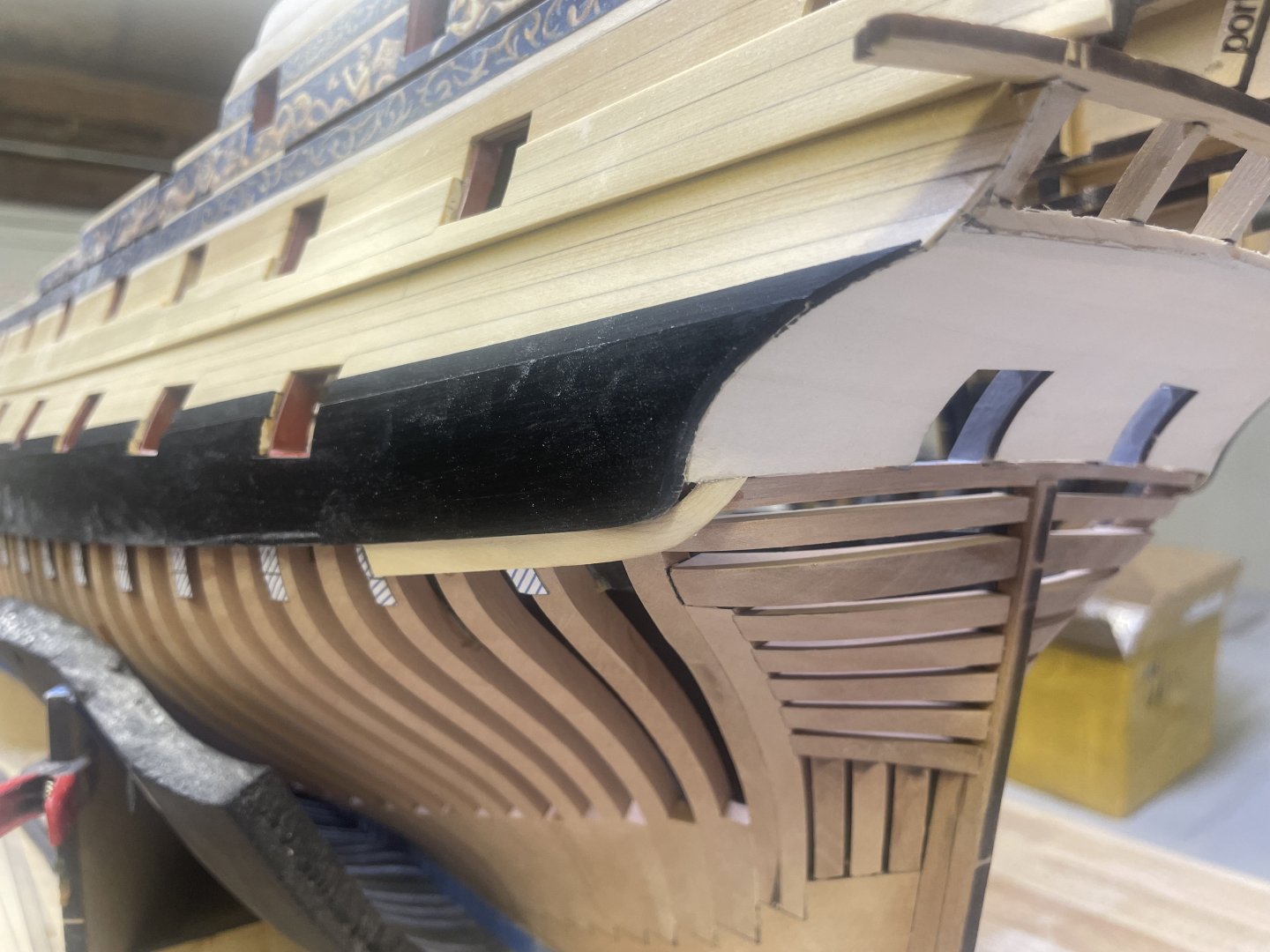
I began fairing the inner hull, as mentioned earlier, the bow needs to be done first in order to install the beak head beam and finish the channel wales. I began by cutting all the extension reenforcement hoops out with a small excel saw blade. MDF cuts like butter so this goes quick from here I faired all the bulkheads down to the first hance piece. I faired enough of the bow aft of the beak head bulkhead beam that I won’t have to worry about coming close to that area then I finish fairing the inside. Now I can complete the channel wale. But before I finish that I moved onto finishing the lower garboard strake plus an additional one. With this complete I could finally add some WOP to the remaining portside hull and frames. Moving on to finish the portside gunports now and finally the last strake at the channel wale.

- 425 replies
-
- 29
-
-
Thank you Ronald! Thank you Kenny. I think the design works well at producing a navy board model without having to fully frame the entire hull only to cover up a ton of expensive pearwood! Thank you Dusan. Soon!
-
The port side planking is complete. Played around with some WOP on the Hawes pieces. Going to start on the garboard strake tonight.


- 425 replies
-
- 27
-
-
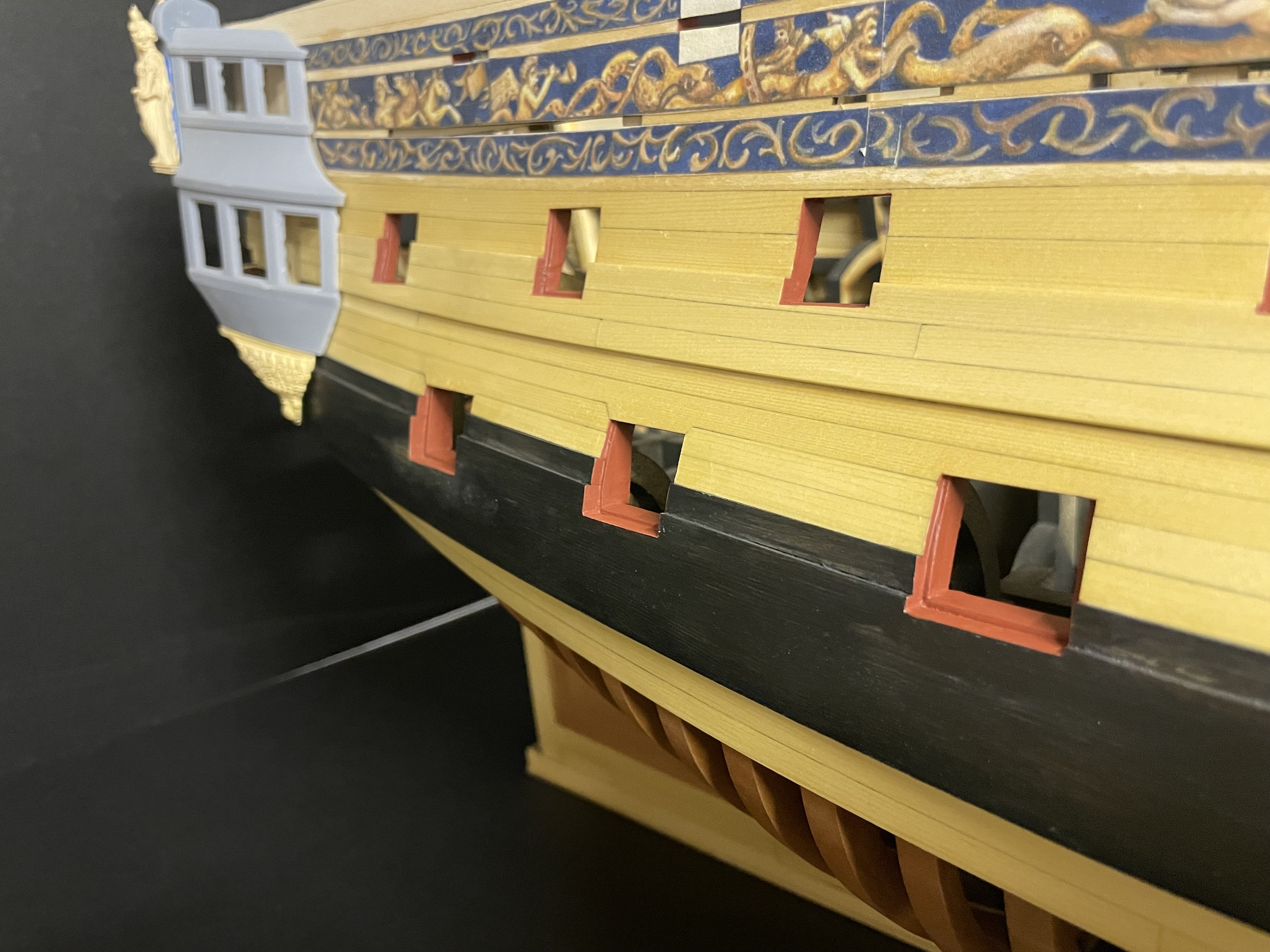
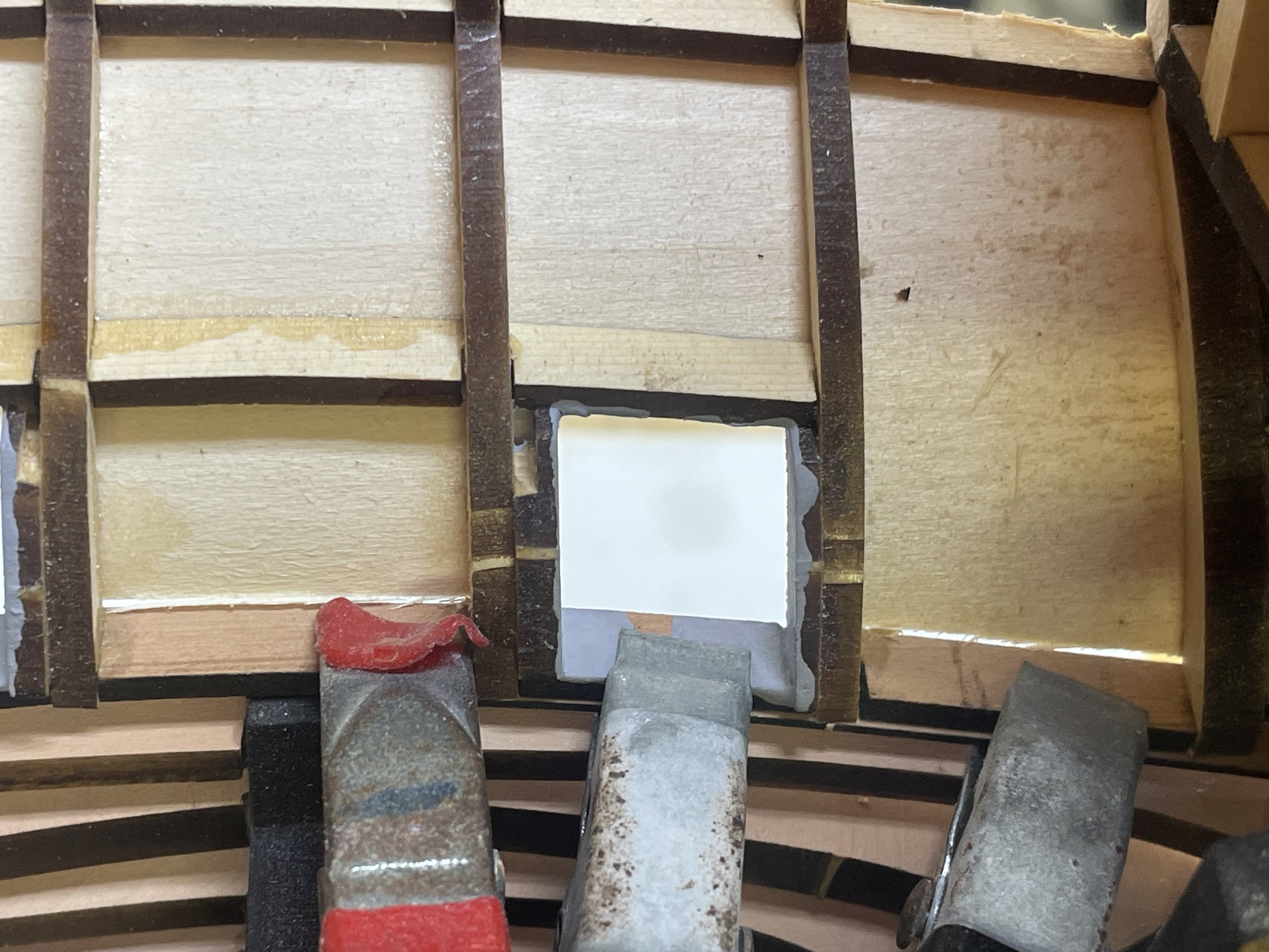
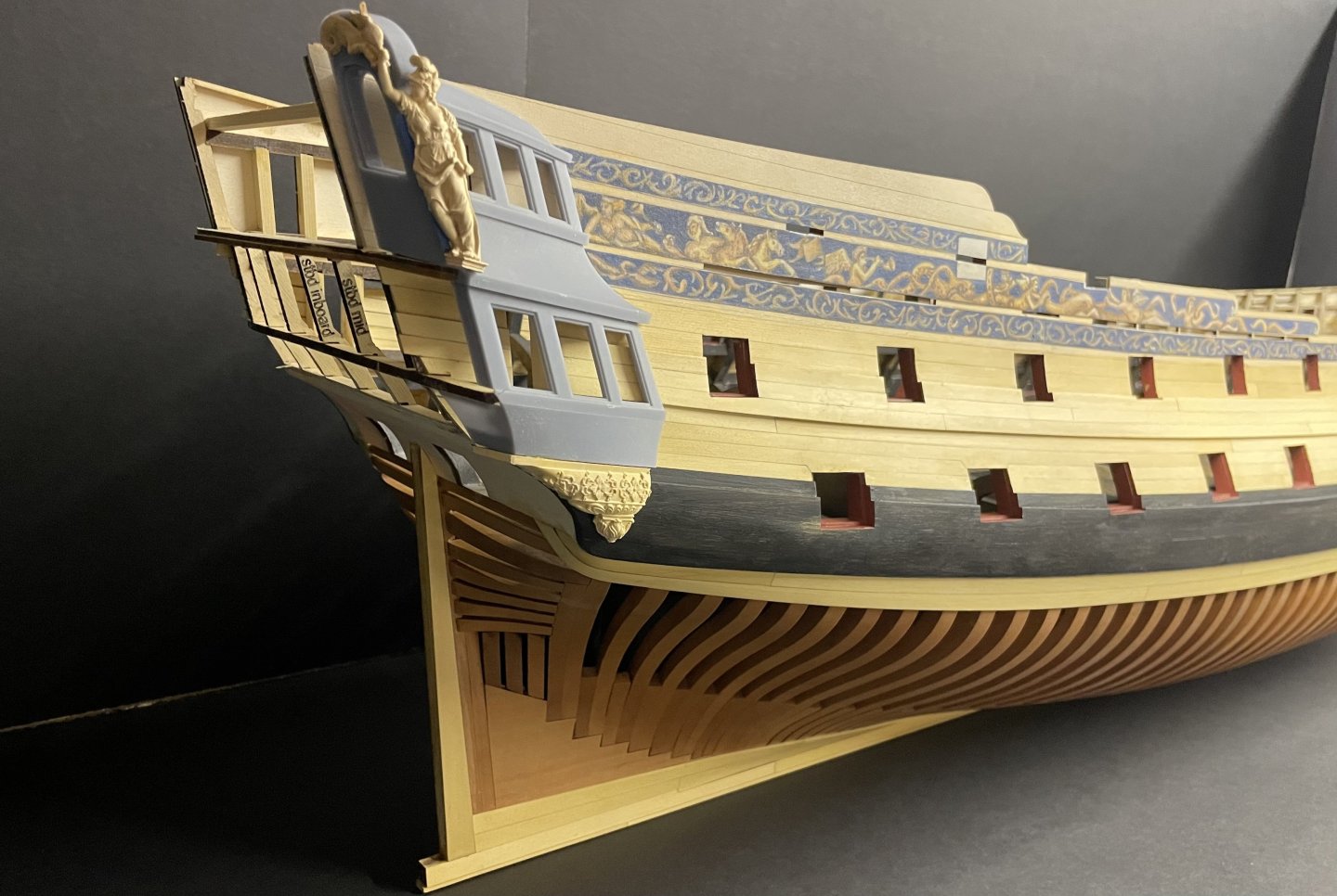
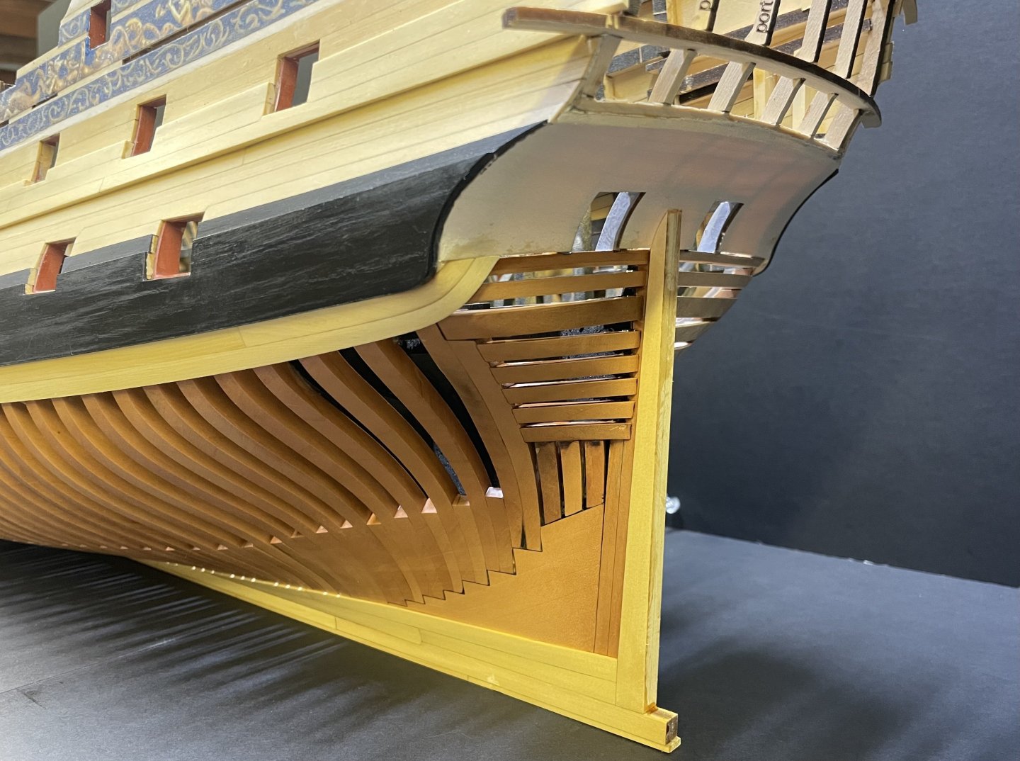
Today I completed the first of two strakes below the main wale. I began with a laminate pear wing transom, this is added to the bottom of the chaser wing transom. First I trimmed up the lower counter so that the bottom is just at the top of the wing transom I then removed the bottom of the outter stern frame with a small razor saw, I then sanded what was left of it flat with a small stick sander the laminate for the bottom of the transom is 3/64” and laser cut Go ahead and clamp the piece in place and test fit a few times, it needs to be up against the inner post nice and tight. The outter edge of it is not as much of a concern as it will have planks covering it. once satisfied with the fit I just coated it in pva and clamped it down. I also used some small wedges on the outside to help with the bond. Once dry it can be block sanded down to match the other transoms, once completed it’s hard to tell it’s even there. There will also be a molding covering the original piece so you will really only see the laminate piece anyway. Now you can begin adding the first strake, I just started from the front and tapered the plank to fit the printed guides. I find it much easier to close up those tricky planks that terminate at the counter by leaving a gap open on the plank just before the last one, after that last plank is fitted then it’s just an easy run between the two ends Once completed a small filler piece was added between the plank and wale, it’s not really necessary as it will be covered by scraped molding but I did it anyway, I saw it done on a contemporary model. Im going to add one more plank after this one and that will be all. But you can see the completed laminate piece compared to the one on the stbd side. if you look up the slots for the stern framing are now covered and the gap is closed up between the two transoms as shown in the drawings. Next up is the garboard strake plus 1, gunports, counter frieze, sternpost and chap 2 is complete. JJ


- 425 replies
-
- 22
-
-
LE CENTAURE 1783 by Jeronimo
scrubbyj427 replied to Jeronimo's topic in - Build logs for subjects built 1751 - 1800
Beautiful work Karl. Just wow! -
It lost a ton of weight too, surprisingly. It’s ok though, we are going to stuff it full of deck beams, planks and guns!..soon.
-
Awesome work Jack!
-
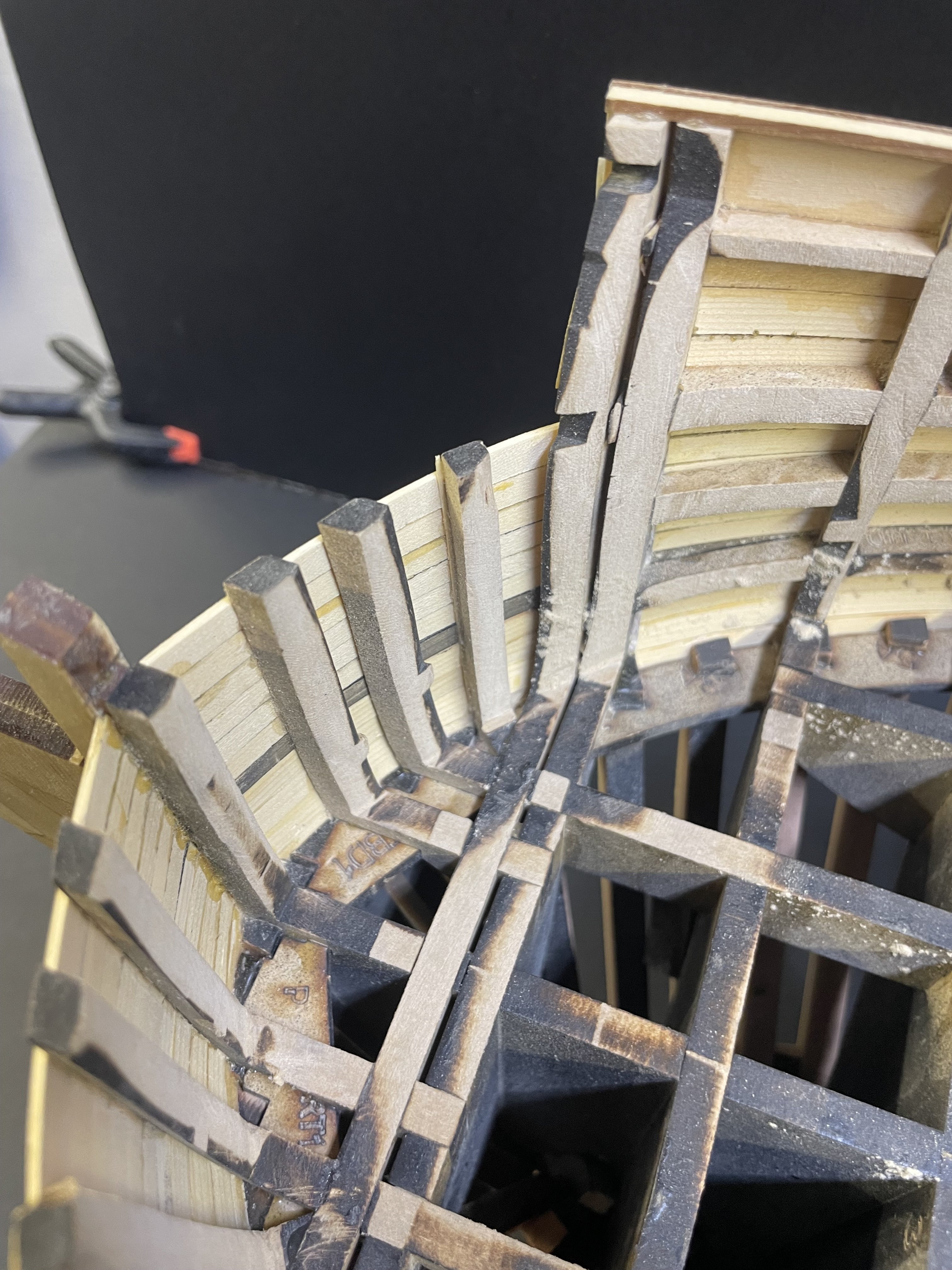
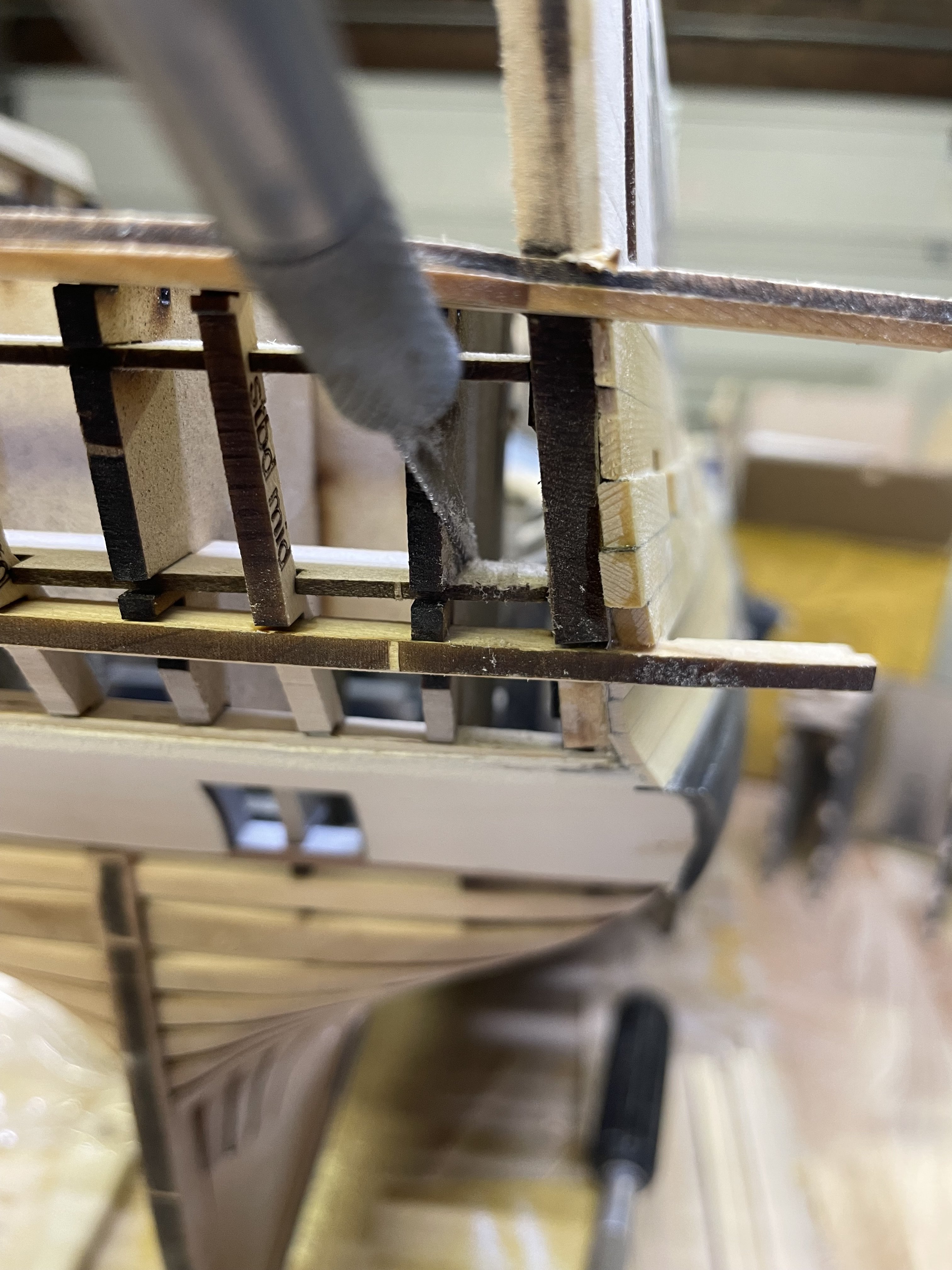
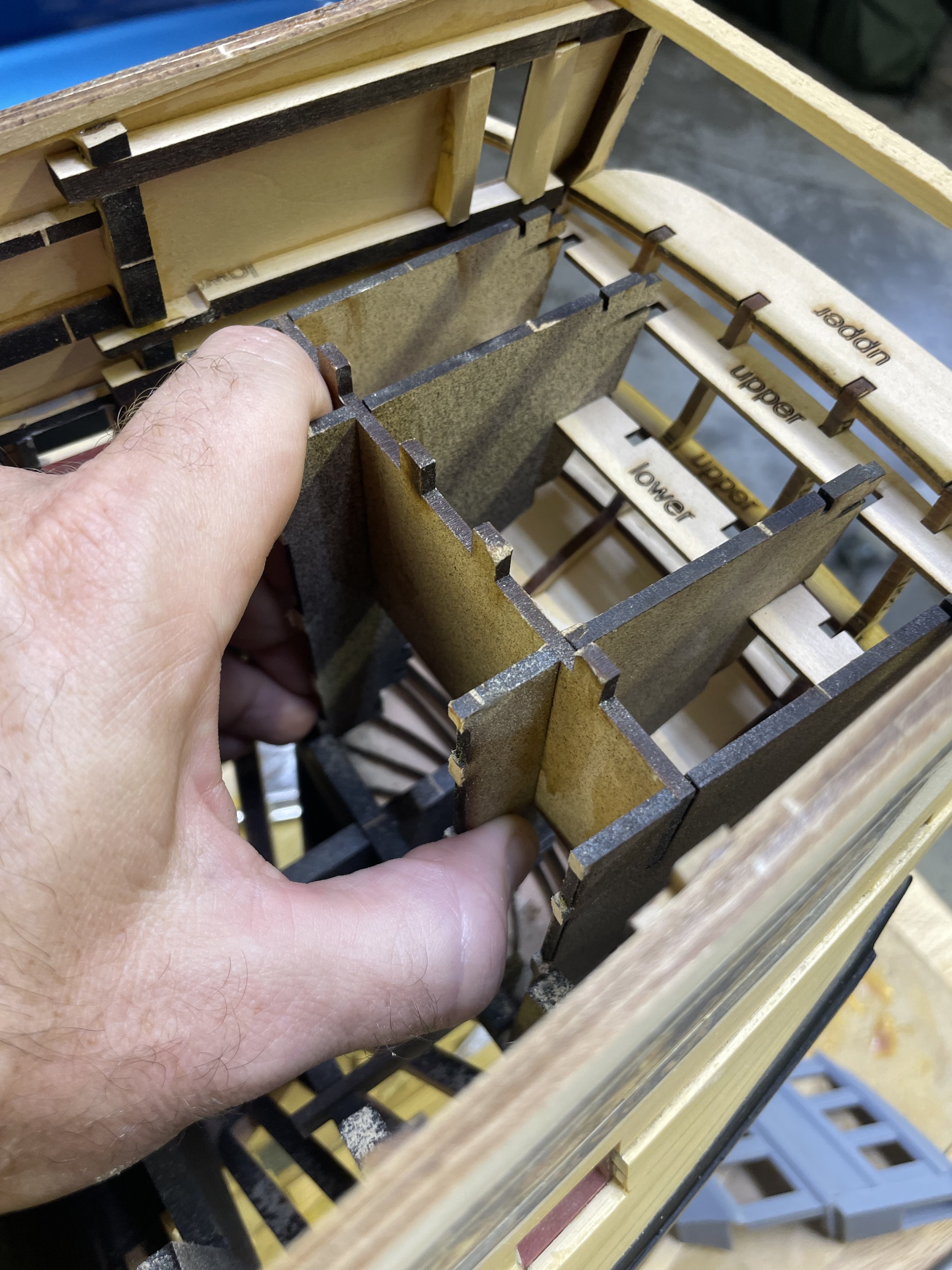
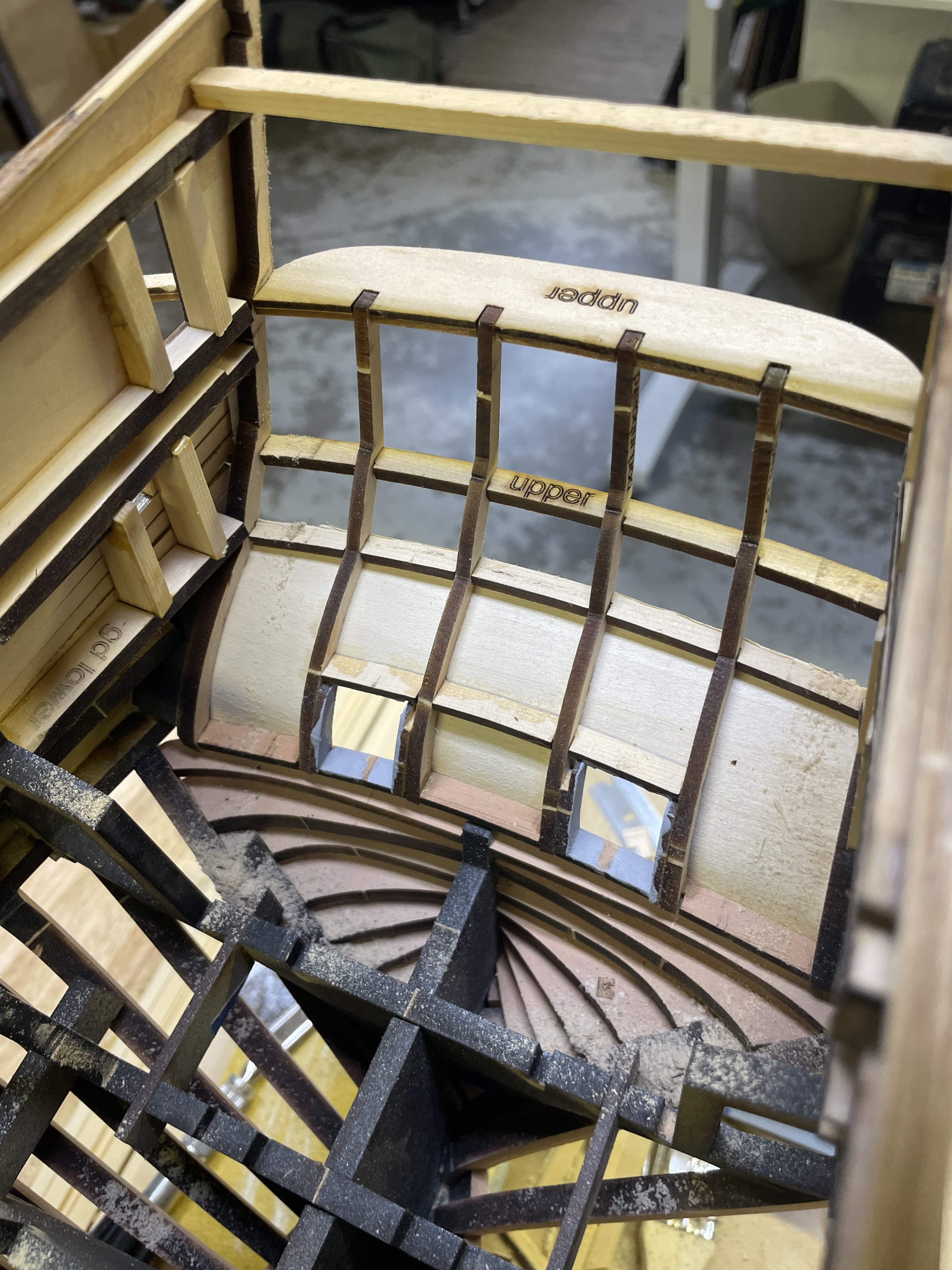
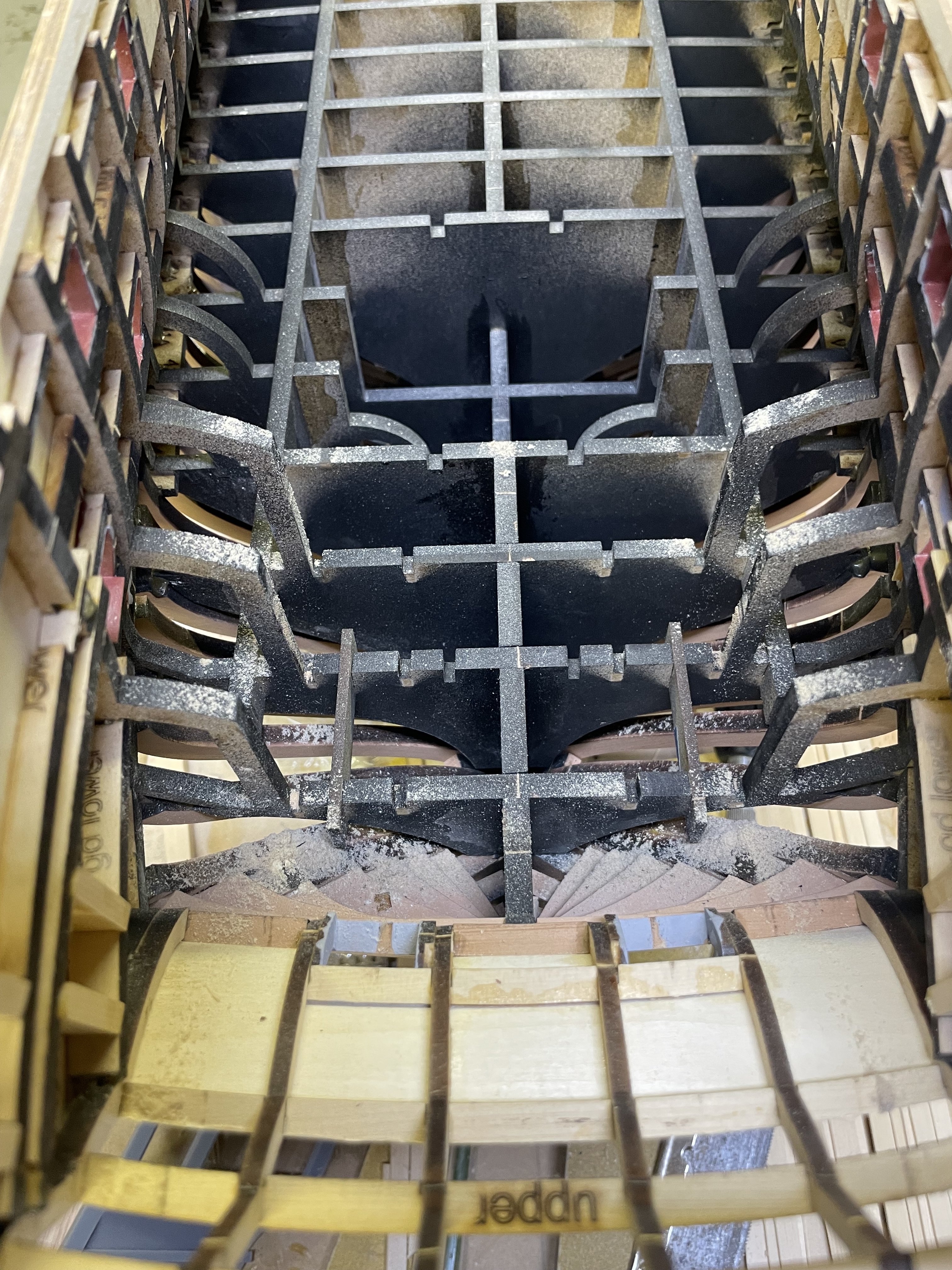
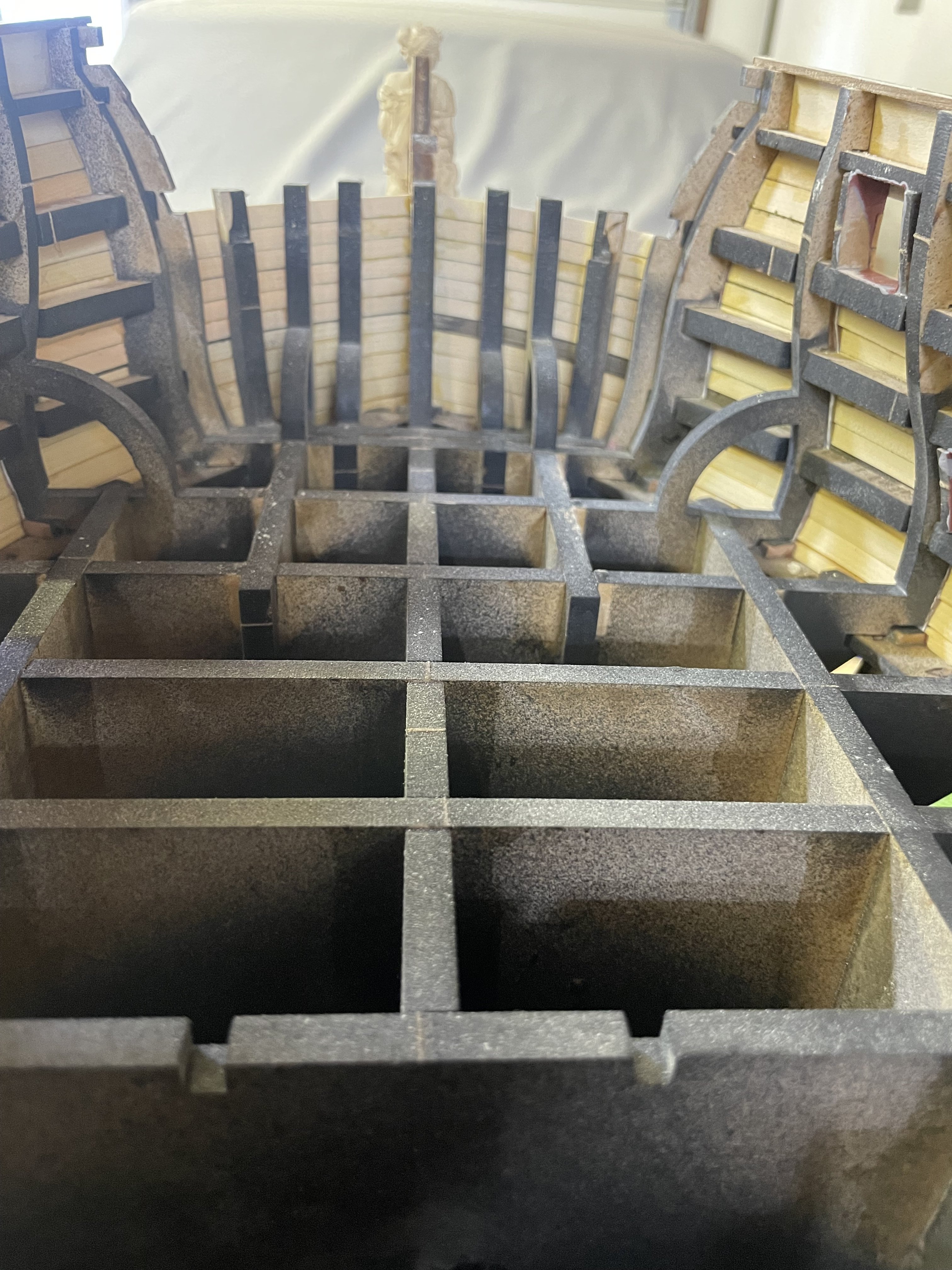
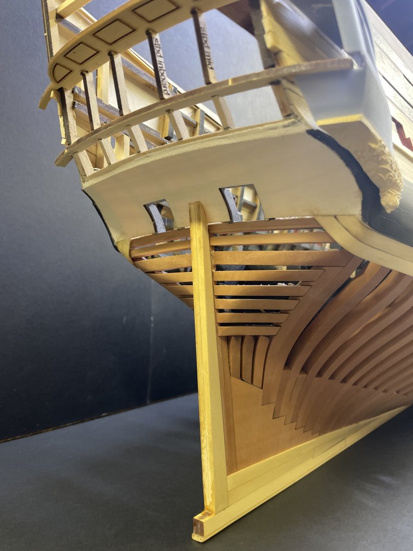
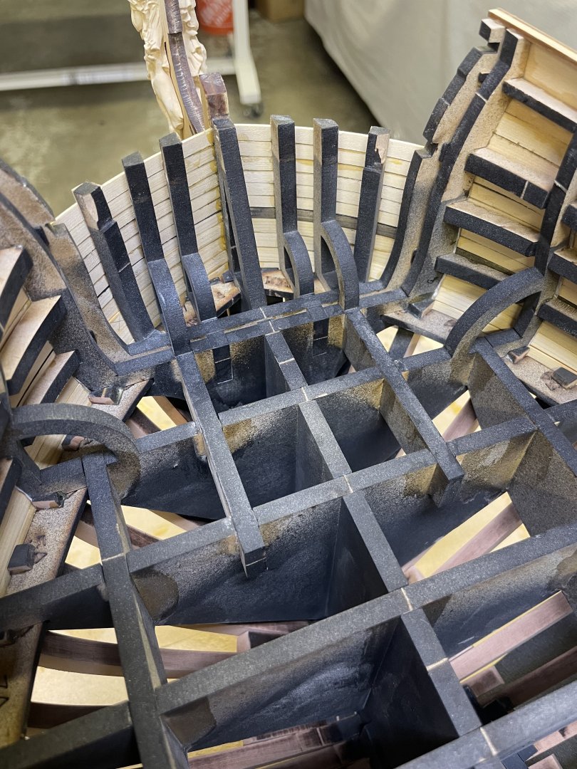
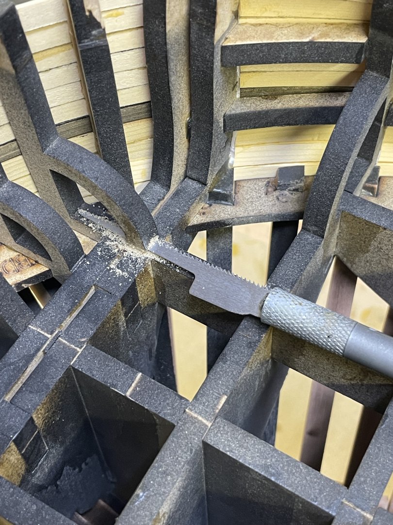
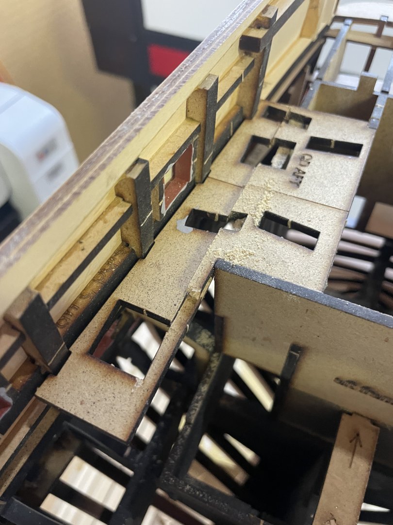
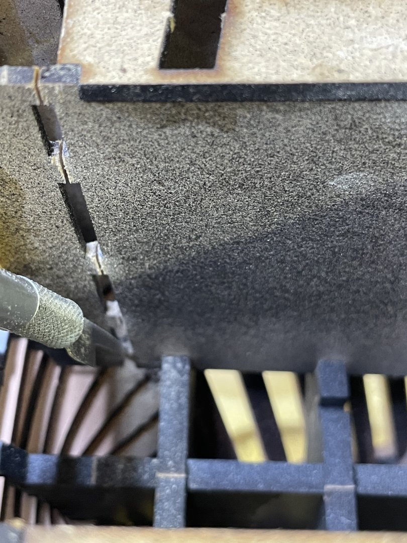
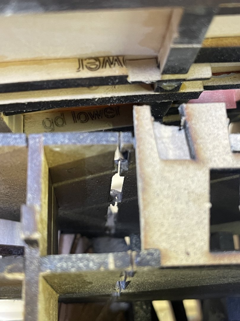
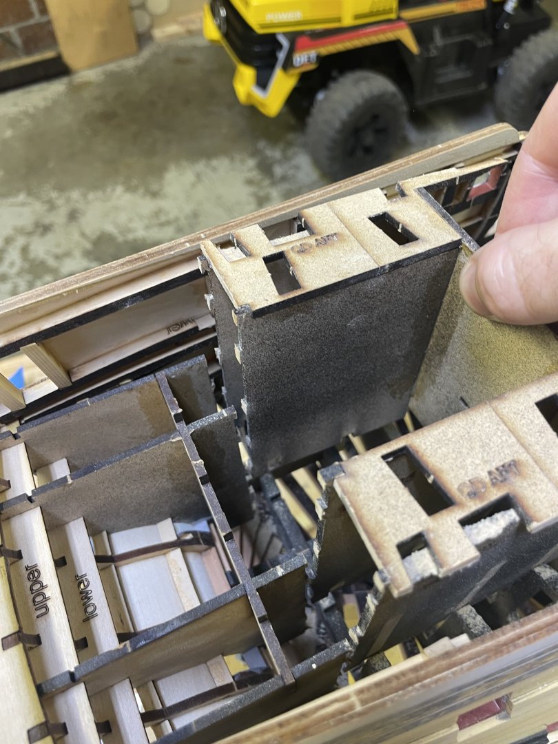
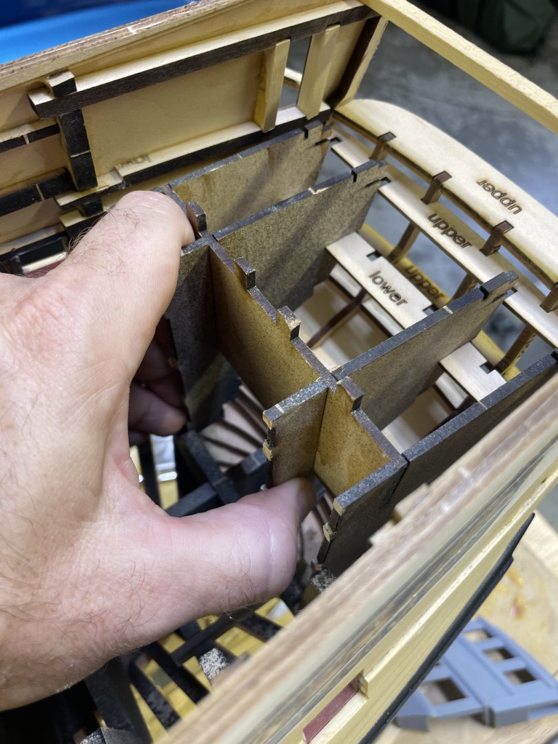
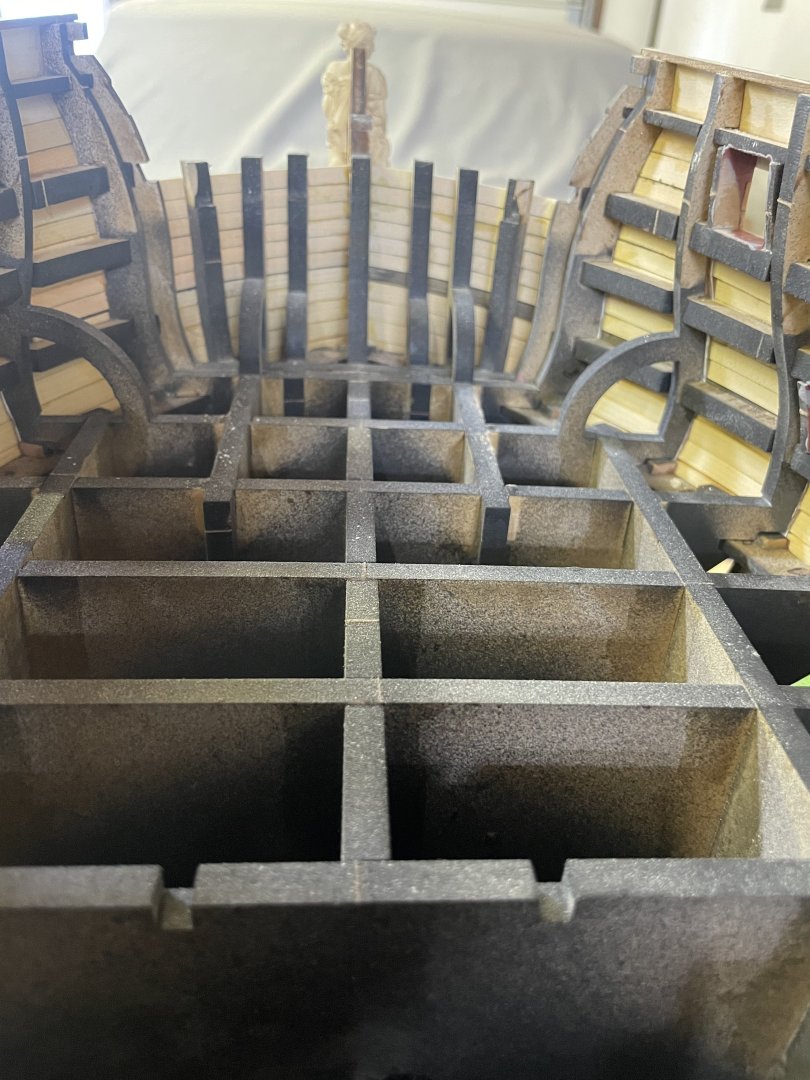
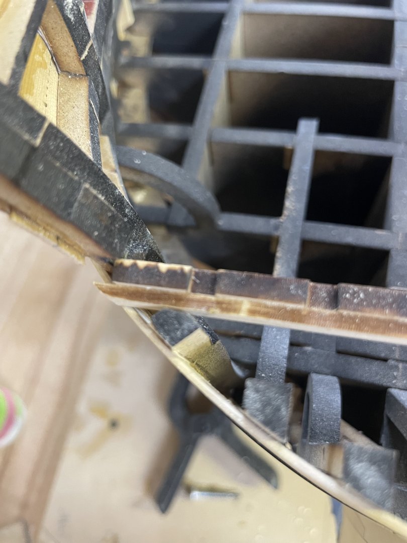
Today I just released the stern frame jig. Now this is a little more complicated than the other parts. It required some cutting, since the main structure of the jig sits down into the bulkheads it needs to be lifted up for removal but we have stern structure that runs across horizontally into slots in the brackets, if we lifted the whole thing it would rip the stern apart. So I added some perforation on the brackets. start by removing the upper extension wing brackets. I just sawed them right down the middle and removed the bracket. From here go ahead and start cutting the perforation I used a micro saw blade on my xacto blade holder and cut them all on each bracket. It’s MDF so it cuts pretty easy. once you have the main part of the Jig cut free it should just lift straight up and away. From there the remaining jig is meant to slide out forward, note that the lower parts of the jig must pass through the slots on the bulkheads that the other part fit in. you may need to saw off the ends of the horizontal frame brackets to help it out easier. If you made it through the stern assembly without gluing any parts to the jig then it should wiggle out gently and then pull right out. now the bulkhead reinforcement hoops can be removed and we can begin fairing the inside of the hull.


- 425 replies
-
- 30
-
-
-
Hi keny, I plan to start producing some in the next couple months. Stay tuned for a website. Thank you Kenny. Should be soon.
-
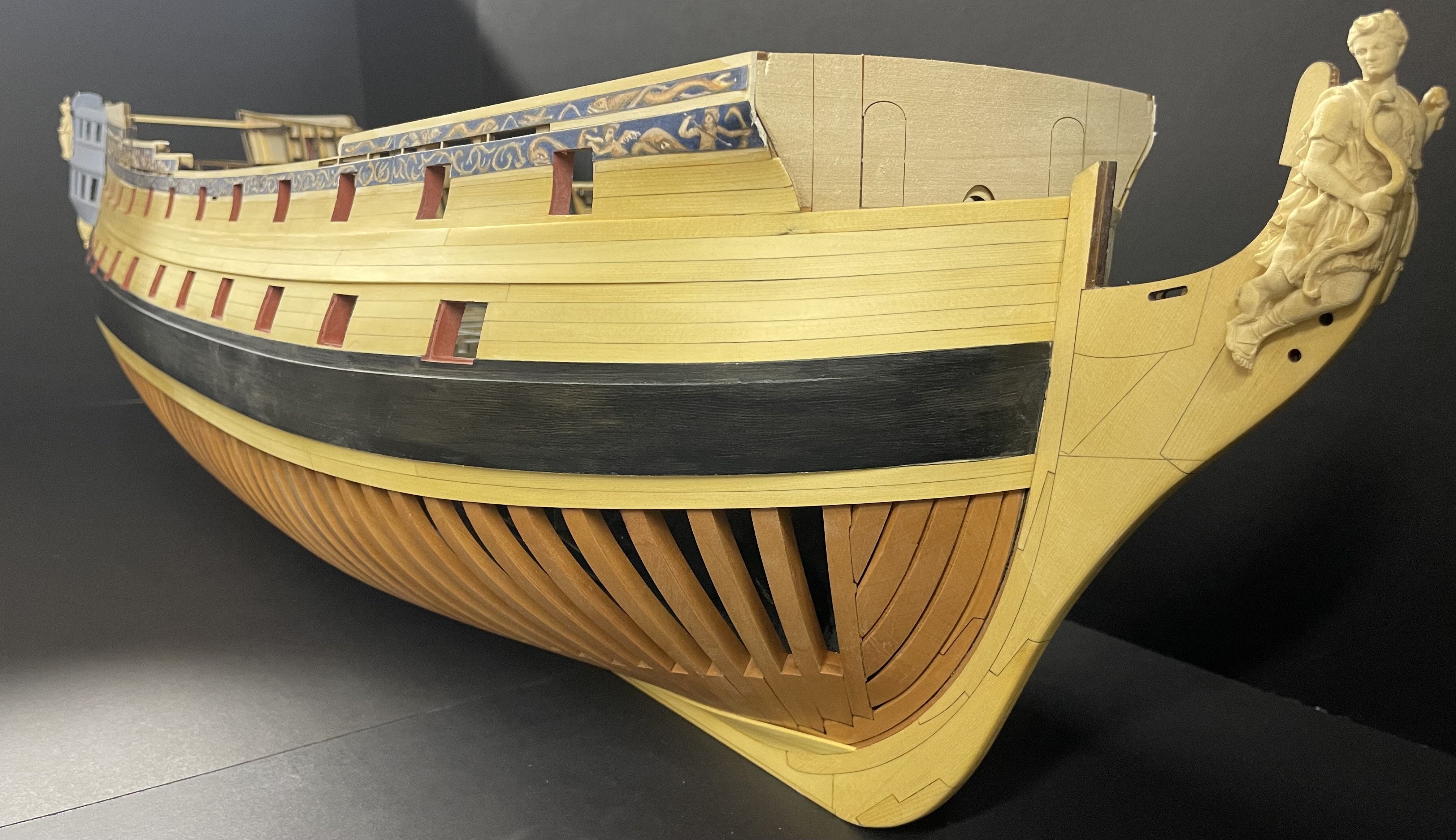
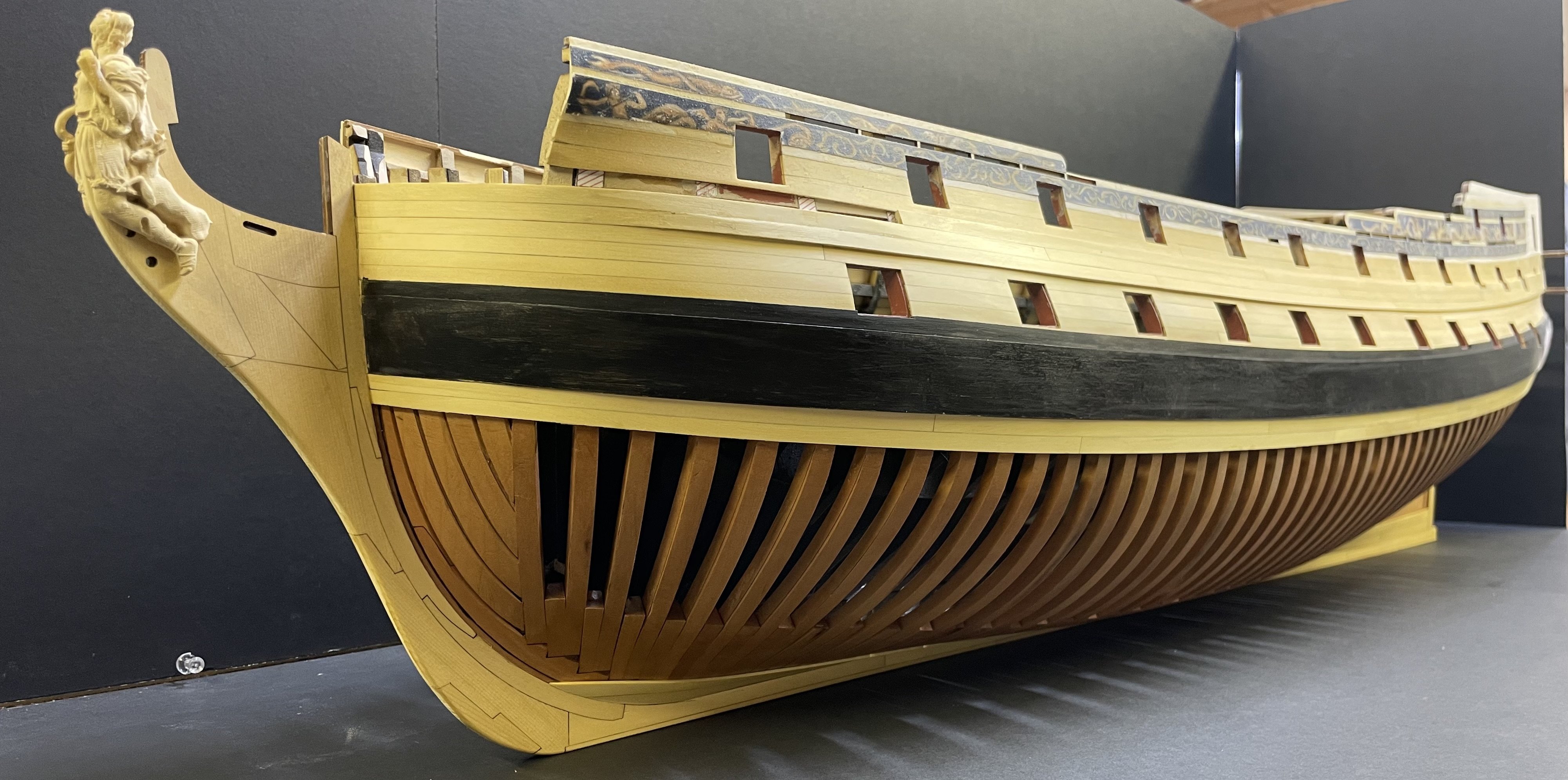
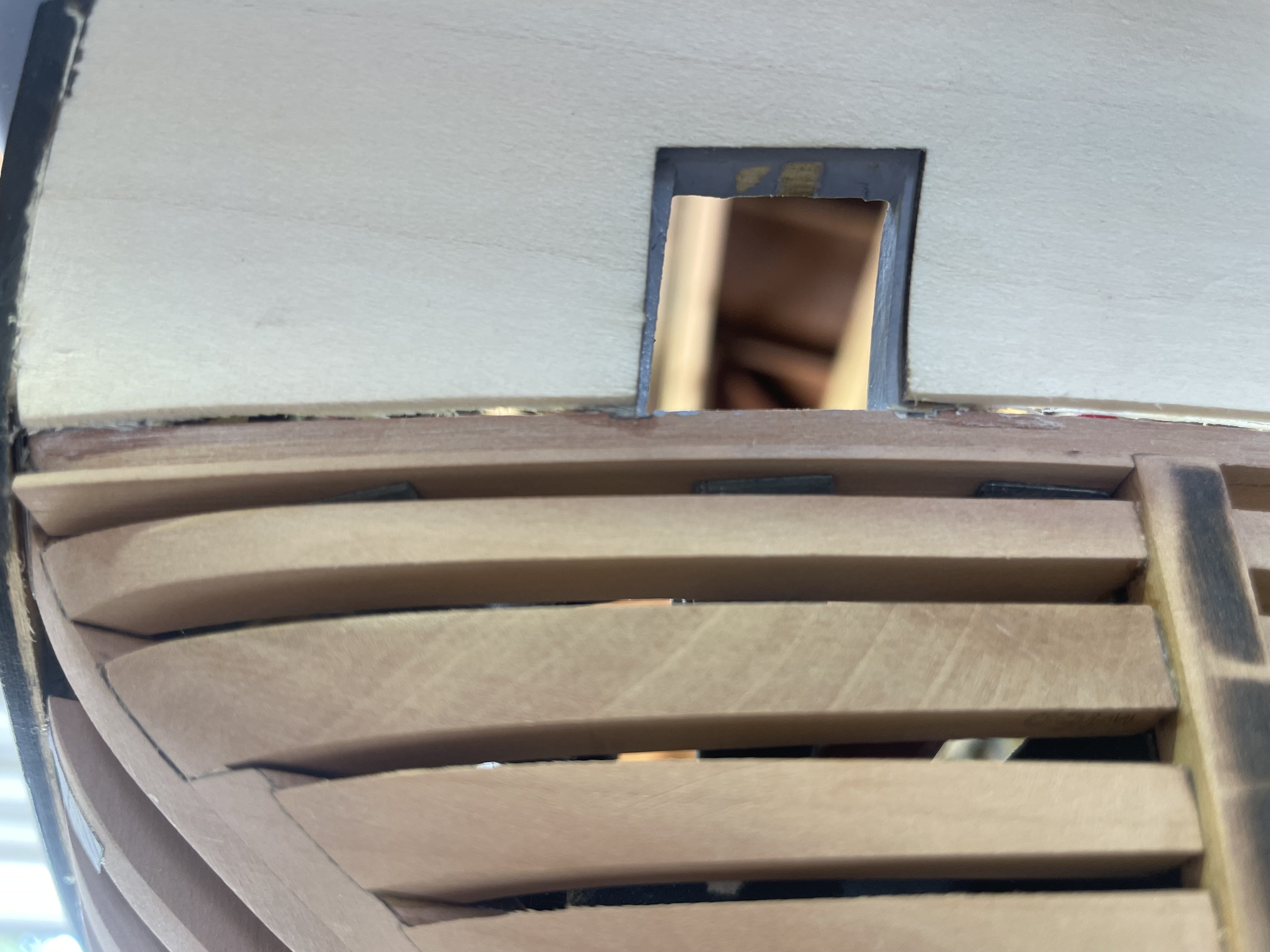
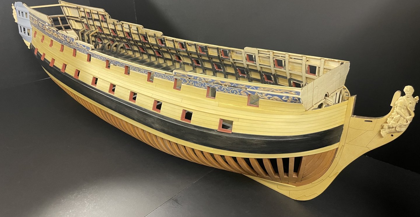
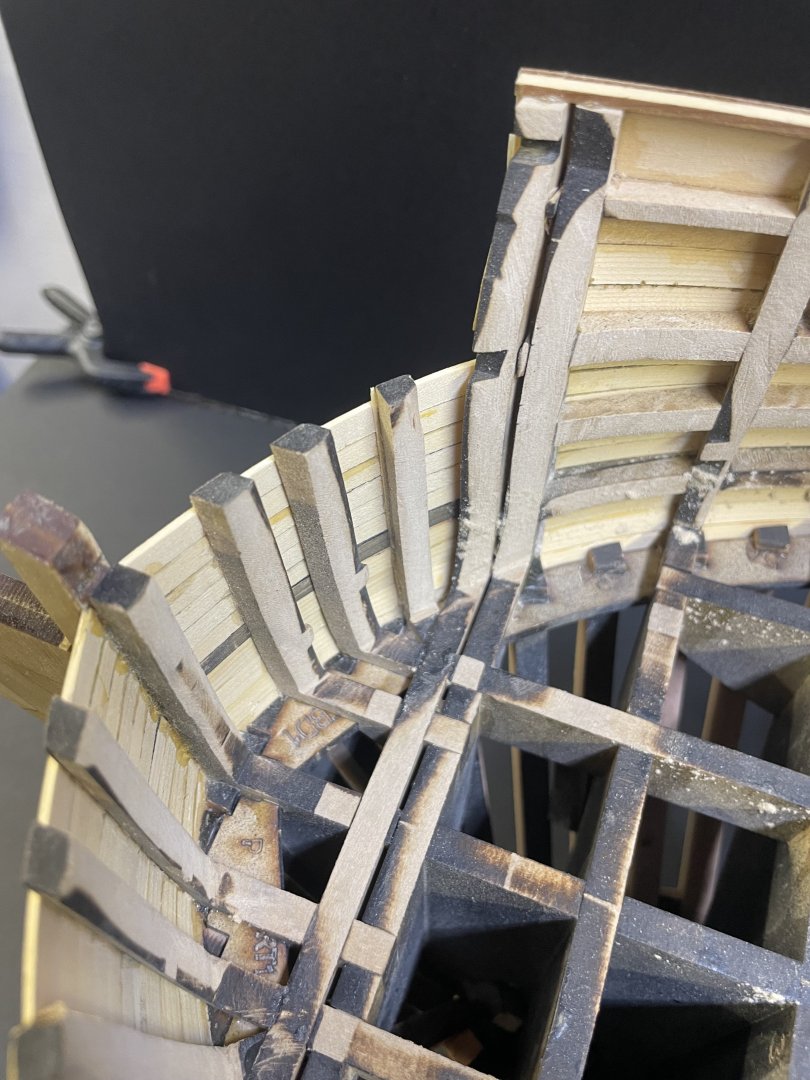
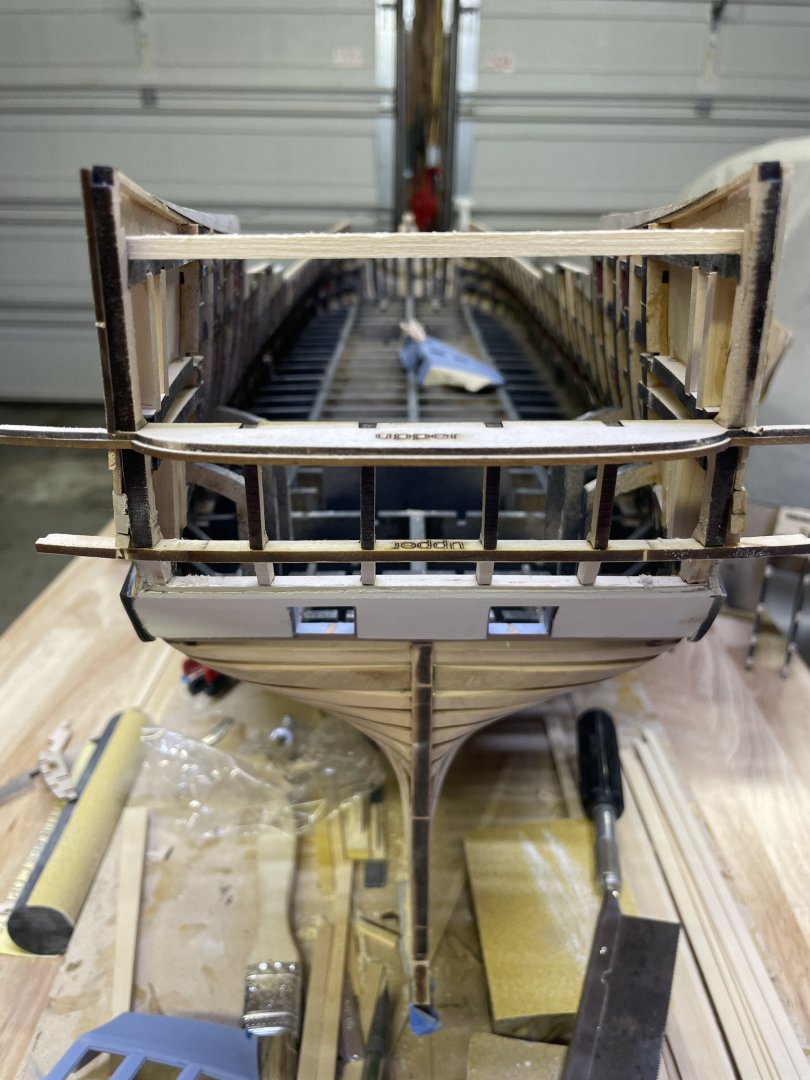
Last night I completed the port side main wale. I also began removing the frame jigs in order to fiar up the inside, especially the bow area so the beak head beam can be permanently installed and the remaining channel wale plank can be installed. I will be removing the stern frame jig soon and that requires a few steps in order to carefully extract it. Will be going over that soon you’ll notice a slight notch was made in the hawse piece to slide the beam by. with the jigs removed and the planking completed (aside from the last channel wale planks), the hull is quite ridged now and will hold its shape without worry.


- 425 replies
-
- 28
-
-
Thank you hmcarlin. I’m very close to having all the ch1 bugs worked out and will be going into producing kits shortly. Thank you VolkerB. Stay tuned. Thank you Glenn. Very much looking forward to adding the carvings and making moldings… all the fun post planking stuff. Haha
-
Great job on your planking! It’s a ton of work but worth it.
-
Thank you Kenny. Looking forward to finally getting back to work! Thank you Christian. Hi Matthias, I started developing them and then quickly realized that I was far from proficient in the software and I was far better off enlisting Jack @Jack H for the job. Jack also produced the carvings for Winnie so I knew I was making a good decision there. Thank you Mike. Thank you Greg, hoping to produce a few test pieces with them soon., I’ll post results. You and me both, Ben. I will have all the planking completed this rotation home.
-
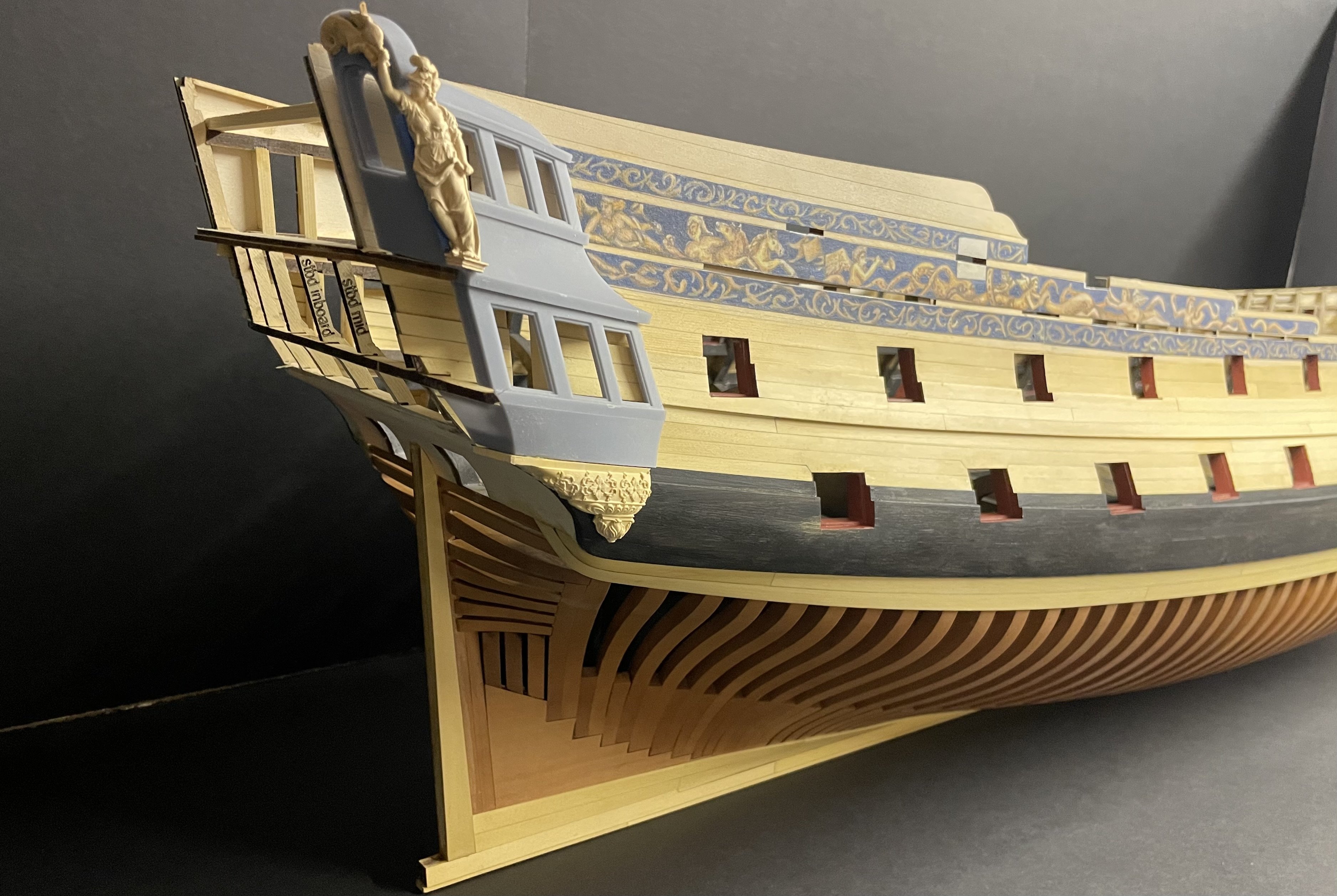
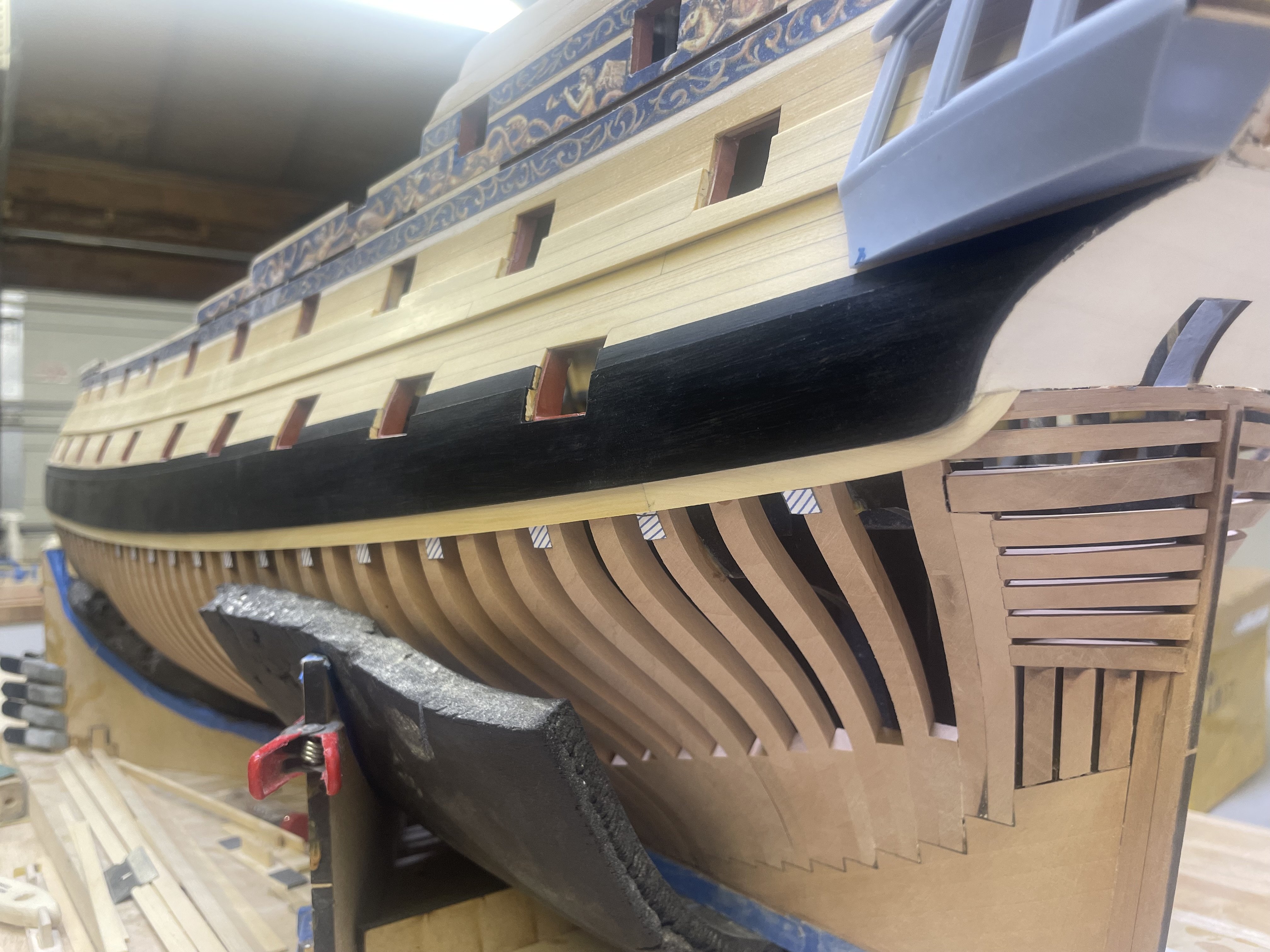
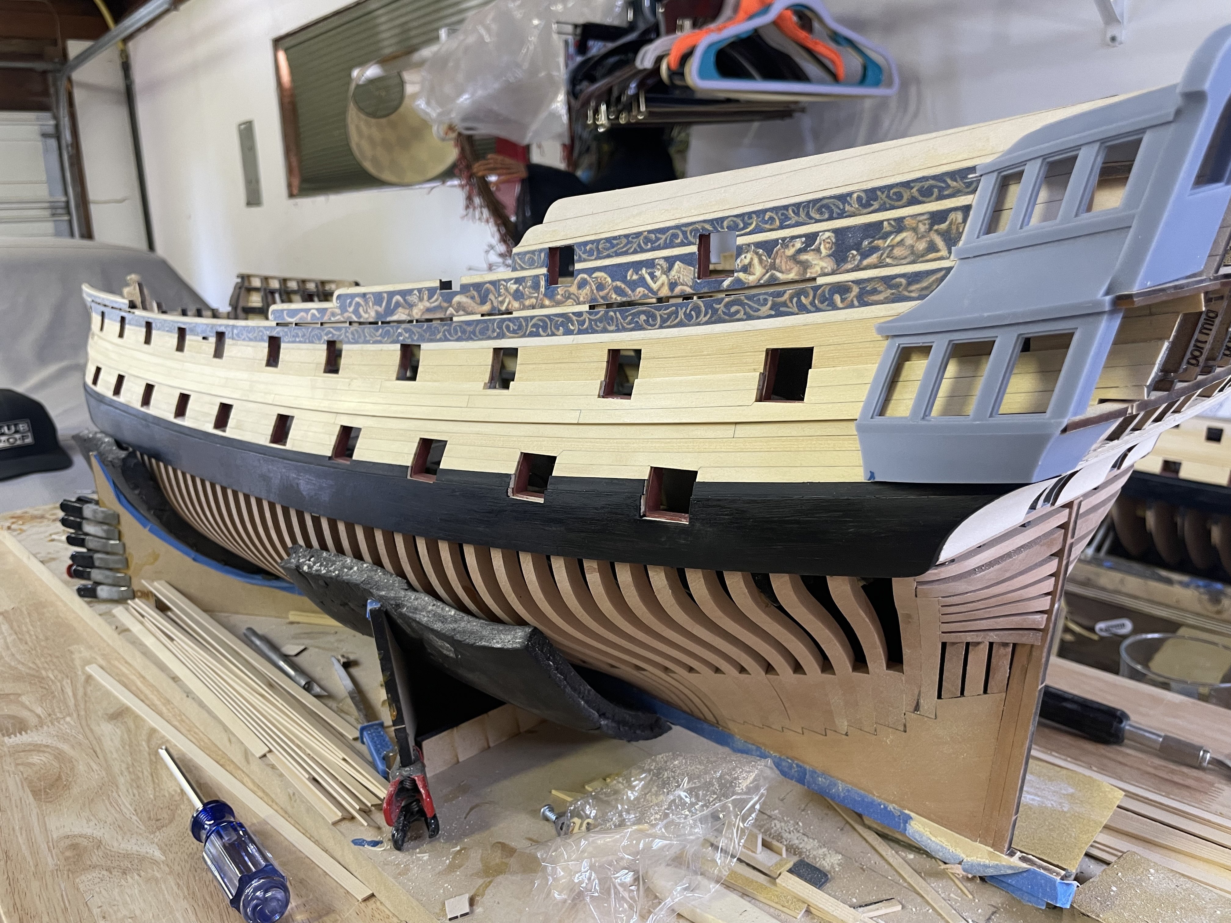
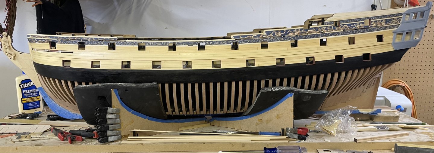
Back at it today with Portland, right off the plane and into the garage! I finished the port side hull planking, got it all blocked out and coated with WOP, now I can move onto the black strake and then the wales. Also some goodies shows up, the remaining carvings for the model. These are the first production run in boxwood and look pretty good. With each set of boxwood carvings you order, a set of stainless scrapers are included. These moulding profiles are taken from the drawings or Portland and the contemporary example of Bristol. The instructions will have a key that shows where each profile belongs on the model. I couldn’t help myself and had to take a test run on a few of the rejects. These are just taped on and fitting pretty rough but you get a good idea of how it will look. There’s still a long way to go on the quarter galleys and the stern of the model. Before the rest of the carvings can be attached. JJ


- 425 replies
-
- 27
-
-
-
Lovely work Frank!
-
Nicely done. She’s starting to look like a proper frigate!
-
L'Amarante by marsalv - 1:36 - POF
scrubbyj427 replied to marsalv's topic in - Build logs for subjects built 1501 - 1750
As always Beautiful work Marsalv! -
Thank you Kenny, stay tuned as I will be updating Portland in a few weeks as I progress into chapter 3 of the build.