HOLIDAY DONATION DRIVE - SUPPORT MSW - DO YOUR PART TO KEEP THIS GREAT FORUM GOING! (89 donations so far out of 49,000 members - C'mon guys!)
×


AON
-
Posts
2,868 -
Joined
-
Last visited
Content Type
Profiles
Forums
Gallery
Events
Everything posted by AON
-
 Good morning Mark, I followed up on the above post of yours. It took quite a while to get all the information which condenses to the following: The document is 6 pages, 10" x 16", at 70 pounds sterling each plus VAT (tax) and shipping. They only offer photos at this time due to the age and condition of them. Photocopying might cause more damage .... however they are digitizing the documents and digital copies may be available in a year or so at reduced pricing.
 -
had to look twice when I saw the moose!
-
hope to see more - espero ver mas
-
Greg, I ordered the book after reading your post copied above. It came in today. Not only do I have the quote in the original print now, it is accompanied by a photo of the figurehead of the Boyne with William III on horseback. A great reference. And then to add to this, I now know the original carver's name (pg. 21) of this original figurehead of HMS Bellerophon as described above. Thank you! Alan
-
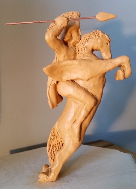
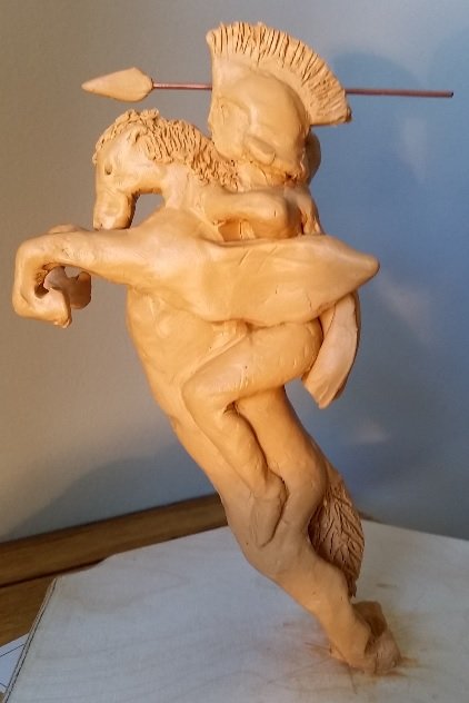
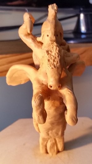
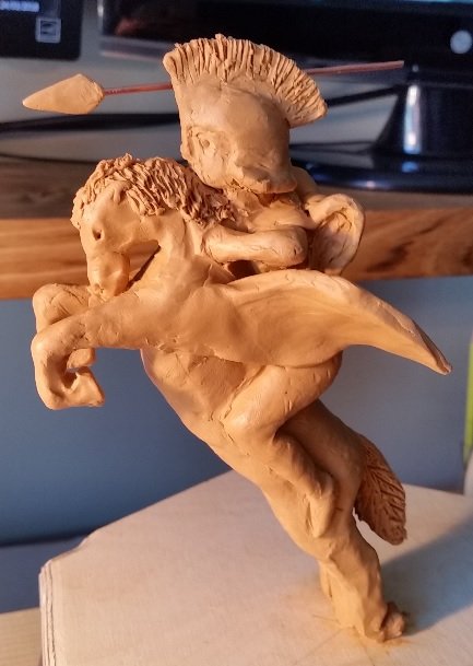
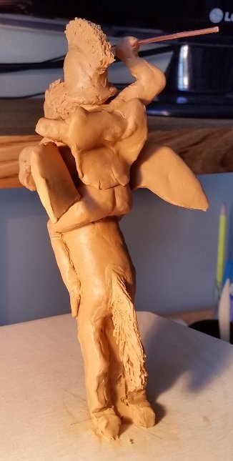
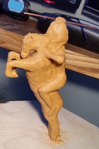
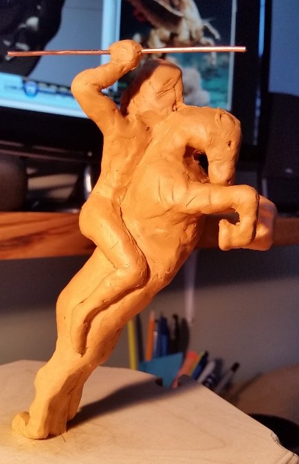
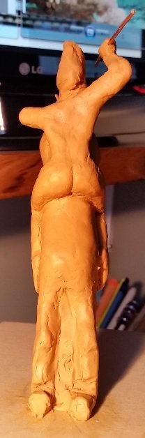
Thank you for the suggestion Carl. I searched on the internet and found a few good examples but after having simply shorten them up I believe they do not look so bad... definitely not as majestic as they could have been but it would have been too ornamental and costly for a mere 74 gun ship of the line . Below are the last of these photos. I shortened the wings, changed the cape, and straightened out his back a bit as with all the handling it was beginning to go into a landing stance . The front and hind legs seem a bit thick but I cannot go much thinner on this clay model. I haven't the skill Later this week I will pick up some squares of Linden (local boxwood) for carving and when I feel the need for a change I will start hacking away to get some 3X enlarged practice sample pieces. Until then I need to get back to making frames.
-
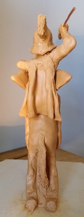
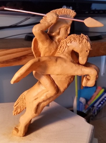
Worked on it a bit more today and I have all the features on. I am not happy with the cape and I can hear one special someone whispering the wings are much to large and would break off with the first wave impact.... but I wanted to see what it would look like. So tomorrow I will work on the cape and cut the wings down to half size with no fold (simplified).2018-03-24 15.25.08.mp4
-
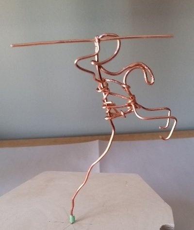
Had my eye injection yesterday. At 10 week intervals now from 4 weeks. Hope to progress to 12 weeks and eventually be healed but that could be 5 to 8 years I am told. So yesterday was an painful day. Today I can see without tearing up or having a massive head/eye ache but I must stay out of dusty environments for 3 days so no shop time for me. So I worked on my Marquette sculpture. Very first attempt. I must say this is fun. Looked through the house for an old wire cloths hanger but everything is plastic! So I used 12 gauge copper wire for the internal support. It seems to be holding up okay. I have to work on the mane, tail, wings, and Bellerophon's head and cloak. That will be tomorrow and Sunday if necessary.

-
Sorry, I was unclear. I did not understand the last sentence: "This also works quite well for bleeding - five minutes of direct pressure by the clock."
-
TMI? I did not understand it.
-
Carl Sorry to confuse you, think of what I was going through! Thank you for the link. It was very informative. Mine will be a pole for now. Eventually it will have a sharp head attached, but it will about 15 feet long only because everything is larger than life when part of a figurehead. Is it a javelin or spear. One thing I know it is not a pike or lance .Alan
-
so size does matter? Many images of the "stick" show it with a head, whereas others do not. According to the story the lead head melted off when the beast breathed fire at it. The melted lead flowed into it's mouth and killed it. So at the beginning of the fight it was a spear and at the end it was a javelin?
-
Is this not a Toe-may-toe Toe-mah-toe type thing?
-
No I have not seen this. Thank you very much.
-
Sorry about that Druxey. I've been e-mailing and texting and tweeting all day and I got mixed up.
-
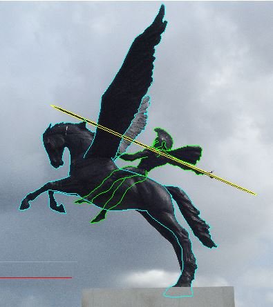
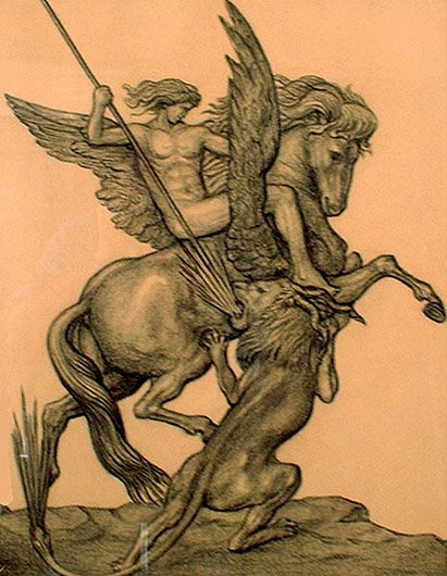
Good evening Mark, I understand that there are no images of the original first figurehead on the first HMS Bellerophon. I could only find a short simple description of it. It, the very first, was damaged early in her career (7 years) and was replaced with a figure of only Bellerophon of which only the head remains at the Museum because the remainder was rotten and or partially destroyed as the hulk "Captivity" was being broken up. When replace in 1793, it was a time when the Naval Board was starting to cut spending and figureheads were getting hit so a simplified figurehead makes sense. I can find no image/sketch/painting of the very first or any full image/sketch/painting of any replacement on the internet or books I have access to. There is only a photograph of the head on display at the museum. Having said that, I also imagine the head in the museum might not be the second figurehead head but possibly a third as she had 30 years service, and had been in a number of notable battles prior to becoming a prison hulk. But of course I cannot substantiate this. I've read NMM has numerous original sketches of figureheads made for board approval prior to the carvers being contracted to work on them but they are not sorted, filed or catalogued as they are considered poorly made sketches... not worth the effort I suppose. So the sketches I've created are my interpretation of the description: "Before it was damaged the figurehead represented Bellerophon as a nude figure draped in a red cloak riding Pegasus, his right arm raised, holding a javelin. The horse’s wings were spread." Source: NMM. I have also read that they were all basically painted white, with very little colour. So from the description I imagine only the cloak was red, Bellerophon, Pegasus and the spear were white. Possibly the javelin (spear) was black(?).
-
David, I will always be interested in any and all comments, suggestions and help. As you know I might circle around a bit before I agree or follow what was actually the best advice. I call this my learning curve. It is steep and mostly my own doing. I have about 20 different images of Bellerophon and Pegasus together and about 17 of Pegasus alone. One has Bellerophon and a wingless Pegasus which in my mind is more believable as the wings represent speed and so do not have to be factual... but then there is the beast to contend with. Of all of these images I've collected only one has the wings behind Bellerophon's legs and I am not a fan of how it looks but I imagine it may have kept his legs from getting beaten and chafed. Here it is... If you have a different one please send it over!
-
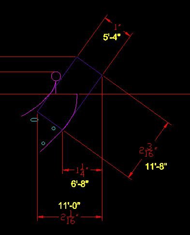
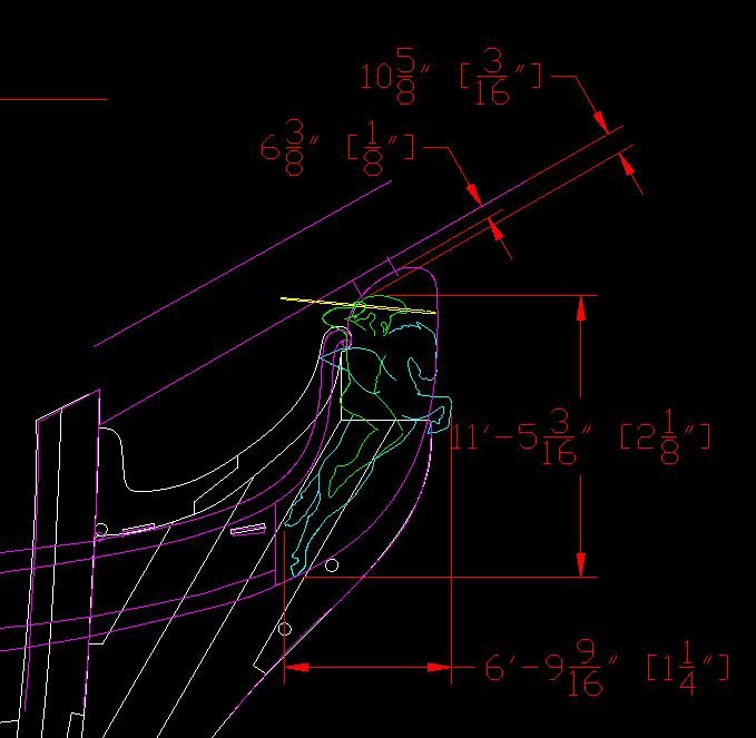
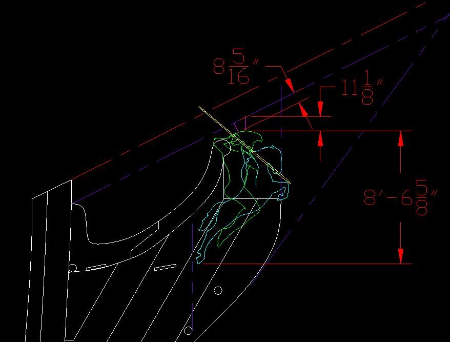
Okay.... inserted the JPEG image of the actual NMM plan and traced it, then scaled it to fit my build scale. Manipulated the figure head items. Here are the results. I added dual dimensions (both imperial feet-inches): actual ship size versus my model size. The model size is quite small.
-
I should have thought of that! I will take a photo off the original plan and insert it.
-
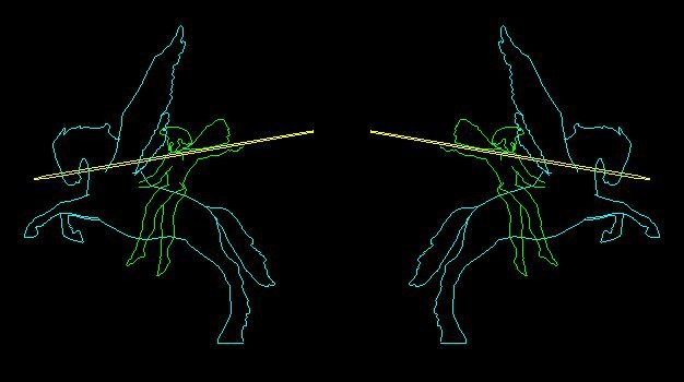
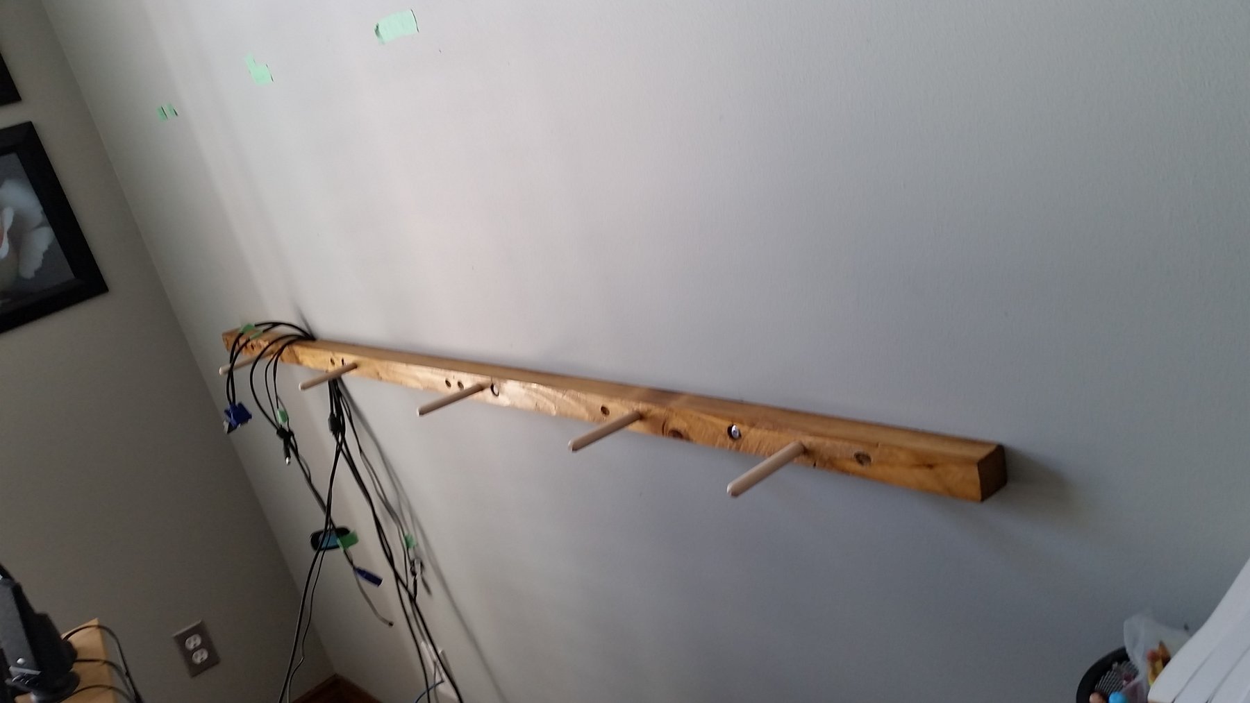
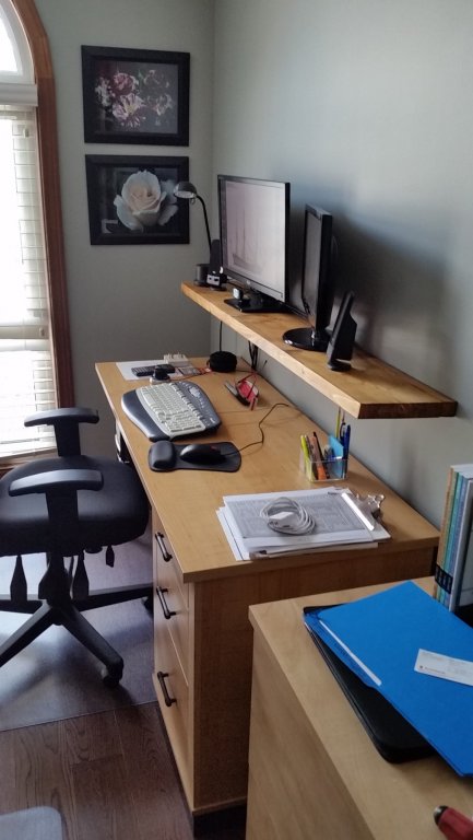
Mounted my floating shelf. Perfect height and matches the desk almost perfectly. The shelf is now out of the shipyard so I can get back to my frames tomorrow. Completed my 13th version of my figurehead sketch. Pegasus is smaller and the body has been arched and rotated to pull the head closer to alignment inside the nose of the bobstay piece. I stole Druxey's hind leg (the sketch off his horse! I wouldn't want to be responsible for him being legless) and arm/spear arrangement. The wings are much smaller. Bellerophon is out of scale with Pegasus but he likely should be the predominate figure. The flying portion of the cloak (scarf) is gone but I feel a wrapped version will appear on the actual figure. I believe I will go with this for now. My wife keeps asking me if I feel retired yet. I have no idea what that should feel like... I suppose that means I was ready.

-
Hour glass??? I am trying to think of it as... I've got enough time left to become an expert in a new career... but what shall it be?
-
Thank you Jason. Very kind words considering how little I think I've done to date. I seem to be following the current and going in big circles. I hope to break out of this pattern soon. At this moment my floating shelf needs another coat of poly, my car cost me dearly (needed new rear brake pads and discs), and my latest plot of a figure head (version 11) is colourized and taped to the wall in front of me so I might ponder on it a bit.
-
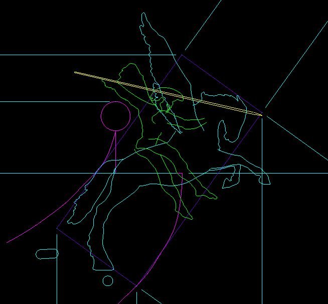
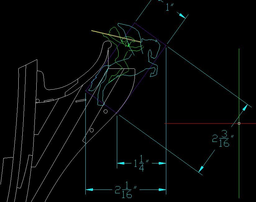
Tried to walk away but I just had to fold his legs back, shorten the wings more, shorten the pointy end of the spear, and clean up (simplify) the horses legs. Now I need to let it rest a few days. Have been looking at numerous other figure heads and rigging and I was thinking along the lines of what you (Druxey) had sketched above. Below is where I went. ... but I admit to liking your sketch a bit more. It fits better, better scale, alleviates concerns for clearance of rigging and bowsprit. At this time sketches cost nothing but spark ideas and give me something to try to whittle (or carve or gouge). I think I have a far trip to develop a talent at this bit of wood magic before it can be considered I've gone to far down the road. I am sure the first 5 to 10 goes would not have a chance to get near my bow! Thank you for having steered me. I have to ask. How did you create such a nice looking sketch so damn fast? (Talent?)
-
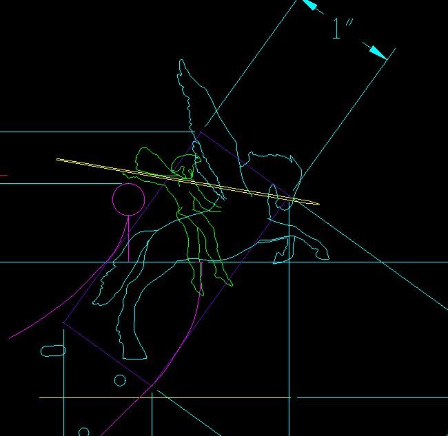
here it is with the bow sketch from my build template (I made the DXF and put it in my sketch).
-
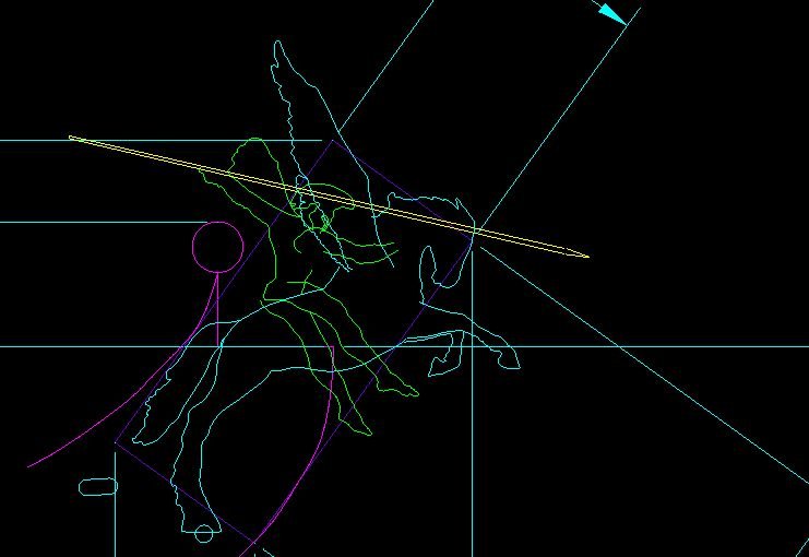
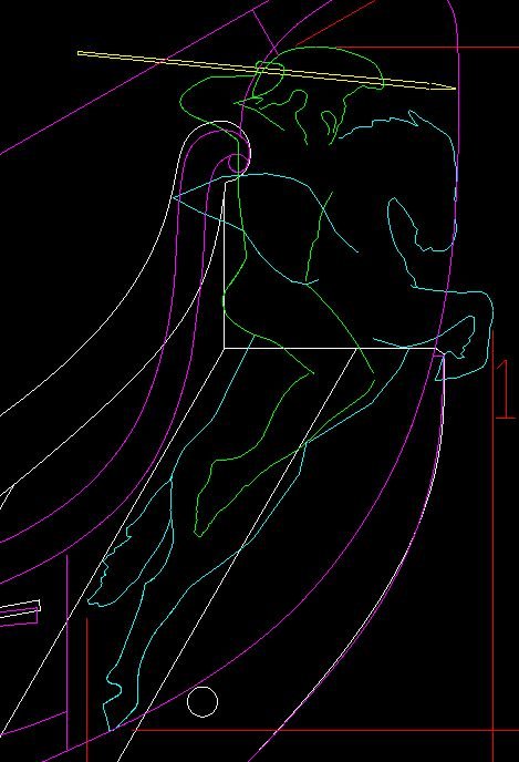
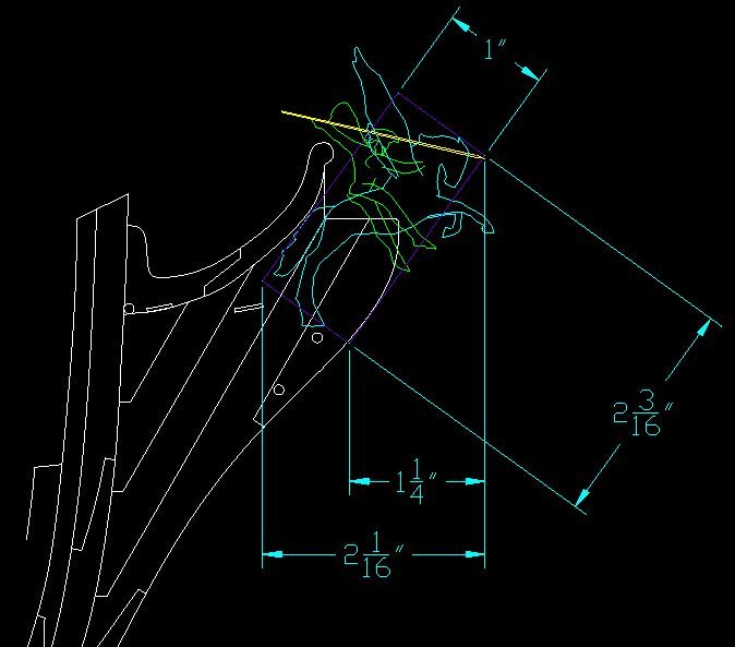
Quite a bit has happened since my last post. I am unofficially retired as of March 3rd (over a week ago). About 9 months earlier than planned but my employer made me an offer I couldn't refuse. Still making frames. Reached over the model and snapped the top timber off one that was still attached. Remade it but none are attached as yet. At the office I stood at my desk 90% of the time (one that adjusted) and now find my home desk computer screen height uncomfortable. So yesterday I made a floating shelf. It has been stained and needs a coat of Polyurethane before it gets mounted. This is taking up room in the shipyard (playroom) so, as I cannot work on the ship at the moment, I decided to work on sketches for my figurehead. I know I am getting way ahead of myself, but I also know this is going to take considerable amount of time, trial and error, to get right... so best start early. After searching the web I decided on an image I liked and might be able to manipulate. I inserted the image into DraftSight (a free downloadable early version of AutoCAD) and traced the image. I worked in layers, hence the three colours to differentiate the layers. I also used polylines and joined as many as possible. I may have the back hoof too big. I then inserted an image of my model's bow layout onto my sheet and traced it. I suppose I should have made a DXF of the drawing, copied and pasted it in. DOH! I'll do that next time when I get a better sense of the figurehead. I scaled the wings smaller as they are a bit large. Then I scaled Pegasus down leaving Bellerophon as is. Then mirrored the whole thing so it was facing the same way as the bow and could be copied into my bow sketch. I inserted this into the bow sketch, scaled it up to suit, rotated and took it in for a bit... let it soak in my brain. Next I rotated Bellerophon, leaning him forward. Rotated his right arm and both legs. and finally shortened the spear. I think she is getting there. The spear isn't quite right. Might need to fold the legs back at the knees. I'll let this percolate a bit and come back to it later. But you can get a sense of where I am going. A special thank you to RMC for sending me some measurements off his Vanguard model and the optional 2nd Bellerophon figure head he had in his kit. I've asked for a couple more measurements to help refine my sketch area. Now I think I'll work on the 1:48 scale template drawings Gary requested a while ago (but I suggested he wait until I retired as I'd have more time then). Then I have a shelf to put up, frames to make and install, take my car in for her regular maintenance....