AON
-
Posts
2,812 -
Joined
-
Last visited
Content Type
Profiles
Forums
Gallery
Events
Everything posted by AON
-
 14 February 2016 is a date worth marking on my calender. The templates are done, checked, rechecked and checked again. (I am sure errors will poke their ugly heads up at some unforgiving time) They will be printed this week and the build begins (again). There are 11 sheets (PDFs to be converted to smaller files and uploaded shortly). The first thing to be made (next weekend) are two wooden combination 1:64 measuring scales or rulers if you prefer (see sheet 6 of 11 bottom left corner). One is 64 feet (12 inches real life) and the other 32 feet (6 inches real life). One side will be a standard scale layout where as the other side will be a centre measuring scale. While measuring off the NMM drawings at 1/4 scale my old drafting scales were invaluable so these should become very helpful in the build. So what have I learnt starting from a blank sheet, working though computer crashes and file losses, corrupted files and basically things that would make a real sailor swear up a storm? I've learnt to realize what 1:64 scale means as opposed to drawing in CAD at full scale (1:1); I've learnt to relax measurements and thoughts; I've learnt patience (a most unnatural state for me); and I've reinforced my "never quit" attitude (Irish stubbornness?). Of course I've also learnt there were many different ways to approach making the templates... but in the end "I did it my way". I've also learnt that all the free eastern hemlock (fir) strapping I've collected from my son's home renovation to use in my build may not be the very best choice of wood for many parts of my build. It is quite grainy and can be an concern. This will be dealt with at a cost I hoped to avoid. A good friend (I hope to have earned the privilege to refer to them as such) has given me a tremendous helping hand to start dealing with this concern. ... and so we begin.
 -
I read the message in my e-mail program and didn't fully understand; then I opened the forum and saw your drawing.... and the light turned on!
- 641 replies
-
- 5
-

-
- greenwich hospital
- barge
- (and 1 more)
-
What a wonderful weekend I have had. I am a firm believer in paying it forward and always try to do the right thing but due to my human failures I sometimes do not succeed. The big guy upstairs knows I try and as I understand it Saint Nick is keeping a score card. Possibly it was karma but someone did a wonderfully unselfish thing for me yesterday which due to their nature I have taken a vow of secrecy but it has restored my belief in the possible goodness of mankind.... and in return I vow to "pay it forward". Thank you. Now, back to my build, or lack thereof. I have completed my templates... twice now. I blame my CDO (or OCD for those that do not suffer from it) but every time I take another good look at it there is something I should tweak or believe could be done better. I swear I am very near a point where even I have to say enough is enough. I imagine it will be in the next few weeks. I have 11 drawings in all and my cost to have reproduced 2 copies of each has been quoted at approx. $80 Cdn (that's about 1 quadrillion US with the way the Canadian dollar is performing) I have removed my earlier PDF's of templates and will be reposting the full set. Then I once again restart cutting wood.
-
We didn't bundle them but then again we weren't flopping about on the deck of a warship! I can imagine things being kept tiddly (tidy / organized) by lashing them together. We also kept all blades in one direction, forward.
-
Back in the 70's we use to store the sweeps (oars) of the 27' whaler's and 32' cutter's under the thwarts on the floor boards. Not sure if you can manage to slide them in but we could.
-
I find matching one side to the other to be very exhausting working. Knowing when to stop is always the biggest challenge because you cannot afford to go too far. I imagine the transoms will be the biggest challenge yet! Can't wait to see you master it!
- 962 replies
-
- 4
-
-
- hahn
- oliver cromwell
- (and 1 more)
-
Very nicely done Mike! Have you finished working on the port side transoms? Alan
- 962 replies
-
- 2
-
-
- hahn
- oliver cromwell
- (and 1 more)
-
might as well grab a couple bottles while you're out there!
- 962 replies
-
- 6
-
-
- hahn
- oliver cromwell
- (and 1 more)
-
I apologize for my somewhat cryptic message above and hope the info I sent you is of some value. I will be following and learning how such a small wonder is performed! Alan
- 28 replies
-
- 2
-
-
- bellerophon
- 74 gun
- (and 1 more)
-
Interesting method! May I ask which ship the plans belong to?
- 28 replies
-
- 2
-
-
- bellerophon
- 74 gun
- (and 1 more)
-
verrrrry nice!
-
love the photos, details, locking cams for chiseling/shaping the deadwood, etc...
-
that is an excellent question that I hope to see an answer to (unfortunately I don't know)
- 962 replies
-
- 2
-
-
- hahn
- oliver cromwell
- (and 1 more)
-
WOW (AND THANK YOU) I'M GOING TO BE STUCK HERE AWHILE!
- 962 replies
-
- 2
-
-
- hahn
- oliver cromwell
- (and 1 more)
-
Mike, Short answer... nope! (I have done a scratch build boat) I fear I may not live long enough to complete the only ship I want to do, so, I dive into the deep end and if I should go "to the place of truth" before it is done I will have at least been working on it.
-
Thank you Don That took about 5 tries to get it looking correct I'm sure a talented modeler would have done better and quicker
-
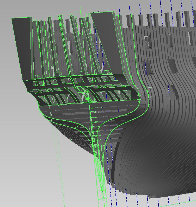
Good morning Druxey Because? I imagined other more substantial reasons! I have purposefully left minute gaps to help me with the breaks between pieces when making the templates My breaks are between full scale 1/2" and 1" (depending on the location) which will not amount to anything in the build (0.016" max) There are also other painful errors, for example there is a ripple in the outer surface of the stealer timbers at the stern below the lower transom pieces but the ripple is outwards and so will sand away if I should happen to be oversize a wee bit. I've tried and tried and it just gets worse so, I've thought it through and have my plan. (I am also sometimes calling Waldo a stealer timber as I haven't found the proper term as yet) There are also a few irregularities in the lower transom pieces that I can fix (blend) easier in the 2D drawing I also left the radii out of the corners of the wing transom as my gut tells me I should gentle do this by eye sanding the pieces I've had to make decisions along the way, and will live and learn by them. Lord knows there is likely something I haven't noticed... seeing the forest for the trees kind of thing. Alan
-
Good morning Mike Yes it has been a long time, no one knows it better than me I had a false start building a year ago but approached it wrong and I didn't like what I had done I have had at least three starts at modelling, this last being a switch from SolidWorks to Inventor. Besides having caught many errors, learned many things about the ship, I also learned about 3D modelling which has been quite valuable for work. Although I do not draw at work anymore (I do not model) my co-workers do, and the mystery surrounding the process is gone. I expect it will take me a few weeks to complete my templates and have two sets printed... then I start. It takes time to clear your head and then the mistakes leap off the screen/sheet and they can be addressed I've been going slower this last attempt at modeling and will be taking my time with the build. This will be my first scratch build "ship" and I am learning so much.... including patience; not something that comes naturally to me It is also the first time I've made my own templates Many firsts happening here It is as much about the journey as it will be the completion. Alan
-
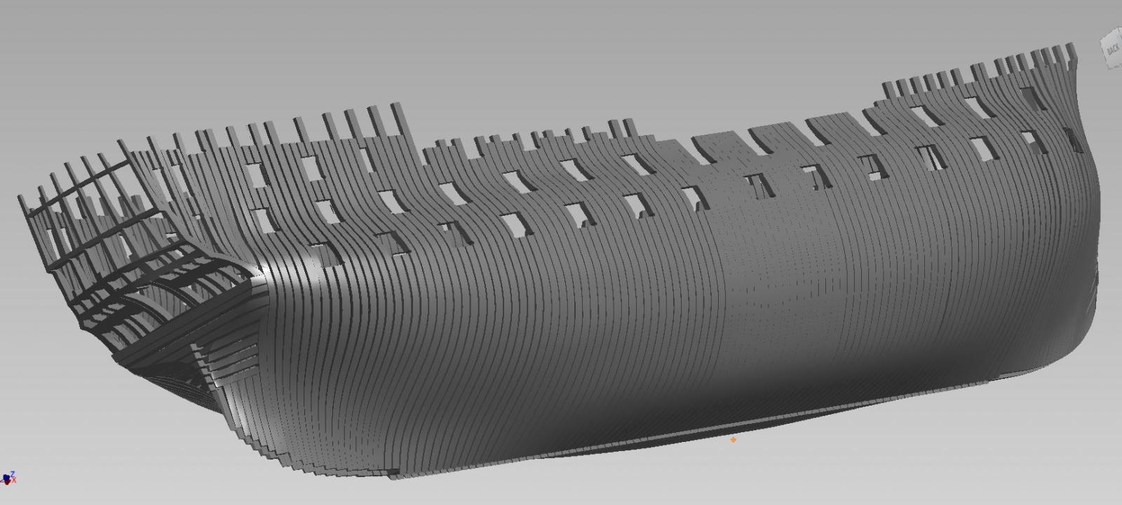
The hull model is as complete as I need to go with her. Now I finish my templates, and will finally be on my way with the build. Why does the last 5% take 25% of the time?
-
gudgeons and pintles alignment and pairing so many small mating pieces can be a challenge!
- 1,616 replies
-
- 5
-
-
- caldercraft
- agamemnon
- (and 1 more)
-
I said I wouldn't but it was such a nightmare to do this last little bit I had to post it It is not completed yet but the worst is over (thanks to my Irish/Scottish/French/Portuguese stubbornness) I present the (uncompleted as yet) "stern"!