


Mark P
-
Posts
1,774 -
Joined
-
Last visited
Content Type
Profiles
Forums
Gallery
Events
Everything posted by Mark P
-
 Good Evening Everyone; Gunwale is the timber otherwise known as the plansheer, or planksheer, which was fitted to the top of the timbers of the main frame, and capped them off. I have not seen cap-rail referred to in any Royal Navy documents, although it is certainly performing a capping function, and may well have been so called in other times or places. When gunpowder weapons were first introduced on board ships, it seems that they were mounted on the top of the ship's side, presumably somewhat like swivel guns, in a metal fork. So the name of the strengthening wale which ran along the top of the waist (and which may well have been called the cap-rail) was presumably changed to gunwale reflect this new use. An important point in the naming of this as the plansheer is that the curved line of the tops of the timbers in the waist, as seen on the sheer plan, is continued along the ship, running right to the stern and bow, and becomes a largely theoretical line which is used to shape the plan of the ship's upperworks at her narrowest point, as shown on the draught, although this is not actually her narrowest point once fore or aft of the hancings, and is only true in the waist. All the best, Mark P
 -
Good Evening Amalio; I agree with Druxey; that is a very clever way of making the same shape of baluster. Thanks for sharing it with us. A beautifully constructed model. All the best, Mark P
-
Good Morning Dave; As you are dealing with the lifts, the item at 'F' will almost certainly be a hook which is put into an eyebolt set in the side of the mast cap. However, in some rigging setups, the lifts also function as topgallant sheets; a resemblance which you noticed. More research needed! All the best, Mark P
-
Thanks for posting this Kiyoo; It is all very interesting, and I look forward to learning more about your process. I can see that I need to learn this 3D stuff (I need it for work as well, so good reason to do so!) All the best, Mark P
-
Good Morning Frolick; If that was just a humourous reaction to the possible double meaning, then ignore the following, but: Just to be sure, and in case this expression is not used in the States, it means to step delicately around something, verbally, which the speaker/writer does not want to mention directly. It can also be used to describe various situations where someone is not exerting themselves hard enough to achieve success. All the best, Mark P
-
Good Evening Everyone; The word which everyone seems to be pussy-footing around so carefully is so old that its origins and early use are hard to trace, with similar words in a variety of languages. However, in medieval times it was a perfectly acceptable word, and did not have the shock-power that can now be attributed to it in some contexts. Sailors, not unnaturally, adopted it to describe something which was as close to the girl back home as they could get whilst at sea (cabin boys excepted, if they were so inclined, of course) And so 'see-you-enn-tee' -splice became an inoffensive and widespread description. I have also seen the word used to describe the place in a tree where the trunk forks into two branches, which usage would doubtless have been familiar to shipwrights selecting trees for felling. In Regency and Georgian times the word is also widespread, and not necessarily shocking, being used in satirical prints as a simple descriptor, along with its more common four letter sibling. Victorian ladies reaching for the smelling salts upon hearing a word which could be sexual in its meaning changed the accepted conditions for using the word, I suspect. So three cheers for sailors and their vocabulary. It's a see-you-enn-tee-splice, so let's call it that! All the best, Mark P Edit: I wrote the proper word, but the site's software has asterisked it out. So I will try a small change.
-
Good Evening George; Thanks for the explanation. Ditto I am familiar with, of course, but I thought that this must be connected with the following words and did not think of ditto. 'Wr' I now remember from other logs long ago, but had forgotten, so glad to have that knocked into my consciousness for future reference. I really enjoy reading old MSS; there is so much to discover. Re Caruana, I managed to track down a copy in Japan, and got it for $250. Very useful book, as Druxey says. On the other hand, when Caruana first published one of his volumes (I think it was vol II) it was reviewed in Model Shipwright, I believe by Robert Gardiner. He was not impressed, and gave it a very negative writeup, listing many errors and oversights. Quite an eye-opener it was. Trouble is, there is no other work to compare with it; at least, not as far as I am aware; and it does contain a lot of useful information. All the best, Mark
-
Good Evening George; The note from the log reads as follows, as best as I can make it out (abbreviations can be difficult to read when dealing with only a small part of a document, so I am not clear on the beginning and a few other bits) Wednesday 7th Notes ?? sent 2 long six pounders ? 12 p? Carronades. shot &c ??? Mr? (Master? Could also be Wm for William but that does not fit context) Shipwrights employed on board. Crew variously received 88 Gall of Beer.
-
This is an absolutely wonderful model! The weathered look of the sails is a great touch, but is only to be expected from such a careful, thoughtful, and incredibly skilled builder. Every little detail of this whole model bears witness to your dedication to producing a truly outstanding contribution to the field of ship modelling. Your methods for building in your chosen material are revelatory, and are, I am sure, an example which has brought the versatility of card to the notice of many who had no idea that such results were possible; and the same with your method of producing the decorative works. I join in with so many others who can only praise your works. Many, many congratulations!! Simply beyond words, really!! All the best, Mark P
- 1,035 replies
-
- 6
-

-

-
- royal katherine
- ship of the line
- (and 1 more)
-
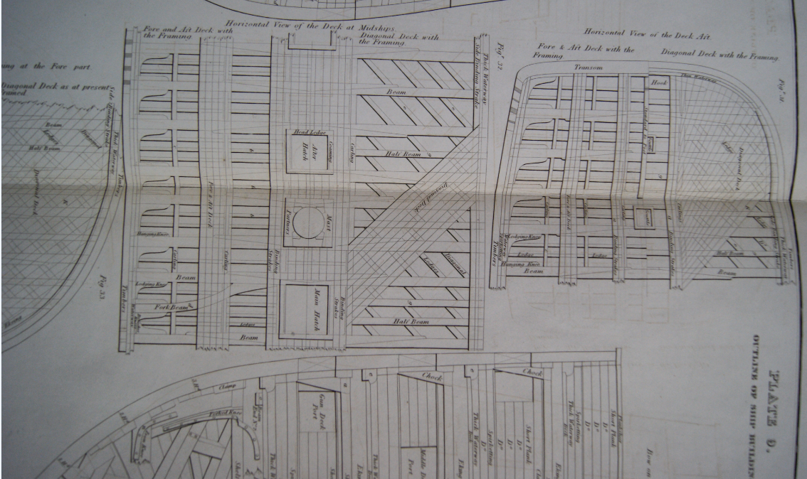
Good Morning Everyone; I can understand the reason for making the lower planking diagonal in a model for strength, if this layer is then covered by a more normally-oriented set of planking. Re full size practice, when Robert Seppings became Surveyor of the Navy in the early 1800s, one of the reforms which he introduced was diagonal deck planking, and diagonal riders. The riders were successful, but the deck planking was dropped after a few years, if I remember correctly. See below part of a plate from John Fincham's works, showing some ways in which this was done. Diagonal ledges seems to run counter to one of his guiding principles though, which were to reduce timber consumption, as well as to add strength. All the best, Mark P
-
Good Evening Helli; If you need to know more about flags used at sea, there is an excellent book by Timothy Wilson 'Flags at Sea', which gives a good history of them and is illustrated with many plates and drawings, some in colour. The flag shown seems to have been in use from the later part of the 19th century All the best, Mark
-
On the subject of tarring the bolt-ropes, this was one of the concerns which arose during the 1618 inquiry into corruption in the Navy Royal during James I's reign. It was claimed (and judging by the number of witnesses to this it was certainly true) that Sir John Trevor, one of the navy board officers, was working in cahoots with a sailmaker named Prusen to ensure a monopoly of sail-making to this one person. High quality canvas would be supposedly delivered into the dockyard stores, and then taken straight out again by the sail-making contractor; at least according to the books this is what happened. In reality, the canvas was delivered straight to the sailmaker. Likewise with the bolt-ropes. The result was that the canvas was never inspected and its value and type confirmed by the dockyard officers. Attempts to deal with this ran into an effective stonewall, as Trevor was seen by the king as trustworthy, and complaints against him were pointless, or more likely to get the complainer into trouble. Similarly, an additional complaint was the sail-maker Prusen would not let any dockyard officers into his premises to inspect the quality of the tarring applied to the bolt-ropes; how effectively it was done, and what quality of tar, rope and canvas was used. The result was that the king was paying top dollar for an inferior product, which endangered sailors' lives. However, the story does prove that bolt-ropes were tarred at least as far back as the early 17th century. The protection of the rope was obviously much more important than the chance of some tar leaching into the canvas. All the best, Mark P
-
Another Steel question
Mark P replied to Don Case's topic in Building, Framing, Planking and plating a ships hull and deck
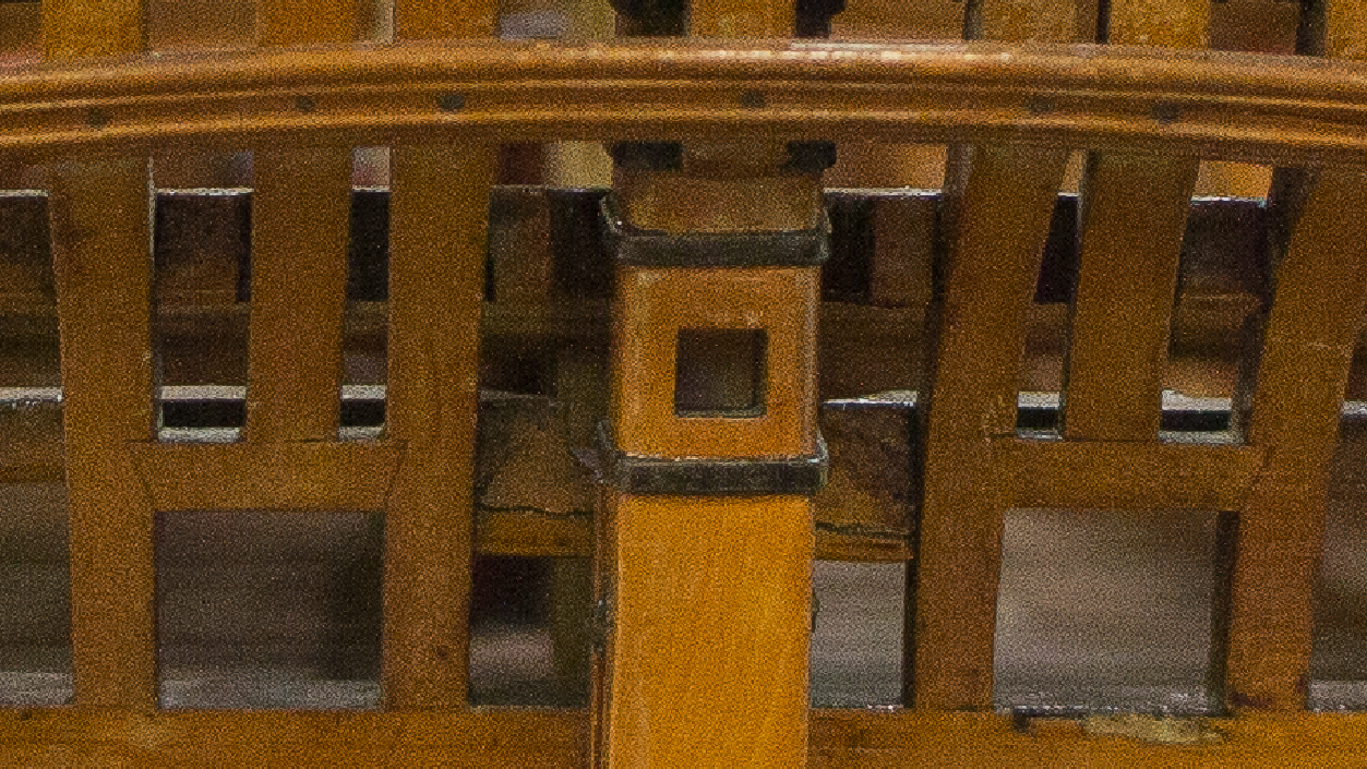
Good Evening Don; In the ships of the Royal Navy, there is no set length as such for the stern post mentioned. It was made as long as possible in order to give the maximum support to the rudder, but in order to allow the tiller to enter the ship and swing to steer the ship, the sternpost had to stop short of the underside of the tiller. Its top coincided with the helm port transom, a specially shaped timber which had a downward cast in its centre, to allow the tiller to swing. The helm port transom could not be maintained in a straight line, or it would have meant that the tops of the stern chase ports would be too low. See attached an excerpt from the NMM's draught of the Dorsetshire's inboard works, which is one of the most beautifully detailed of its kind around. Next below is a picture of the stern of the framed model of the Bellona, also in the NMM. In between the gunports you can see the downward cast section of the helm port transom, with the higher sections of it running thwartships on either side. Above the hole for the tiller, you can see the deck transom, which had to pass over the tiller. This set the maximum height for the tiller; as you will see from this, the positioning of the timbers in this area is inter-dependent. All the best, Mark P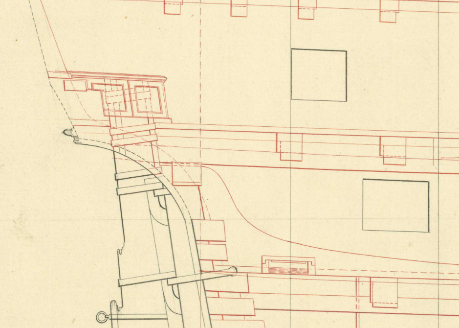
- 1 reply
-
- 2
-
-
Good Evening Don; To the best of my knowledge, the keel was laid straight, and the hog was laid on top with an equal height for its own full length. I have not seen anything to indicate otherwise. Which is not to say that it was not done, but I am not aware of it. The heavy timbers of the various wales, with their exaggeratedly curved 'sheer' were intended to counteract the tendency of the ship's ends to droop, and I doubt that building a small amount of curve along the keel would achieve much; bearing in mind that ships were also subject to the opposite stress, with the centre of the hull sagging downwards when passing over the trough between two large waves, so that there is good reason to avoid building in a pre-formed 'sag'. Incidentally, deadwood is not the same as rising wood; at least not as it is generally accepted/used. Rising wood (hog) is located under the straight floors, stretching fore and aft from midships. Deadwood starts where the rising wood ends, and is used at the extremities, bow and stern. The deadwood is built up in layers to form a base for the half-timbers and 'V' shaped, made floors (also called hooks) However, you will come across deadwood and rising wood used interchangeably in some modern works, and even some contemporary documents, so the definition is not completely clear-cut. Also, chock covers a multitude of uses, sizes and shapes. For example, there are chocks which are completely parallel-sided; polygonal chocks to join the futtocks; and triangle-based chocks in the floor timbers and transoms, amongst others. More to think about! All the best, Mark P
-
Good Evening Don; I assume from your reference to Steel that you are looking at a ship from the Royal Navy in the later 18th century. Most tables of scantlings, or contracts, give a dimension for floor timbers 'on the keel', which is measuring upwards from the top of the keel. Depending upon the period in question, this will actually be measured upwards from the top of the hog, or rising wood, which is a length of timber laid on top of the keel to make it easier to form the 'deadrise'. This latter is the gently sloping part of the ship's bottom, starting immediately on each side of the keel, which is sometimes a straight line, but often a shallow curve, sometimes combined with a straight line. The amount of deadrise is normally specified in a contract, and is measured from the top of rabbet for the garboard plank in the keel, to the underside of the floor timber where it crosses the keel (or hog if fitted) Although models usually have floor timbers made in one horizontal piece, with the bottom tapering downwards towards the keel, in full-size practice it was normal for the floor timber to have its top and bottom parallel for most of its length, and to fit a triangular 'chock' under the floor timber on each side, which ran into the side of the rising wood. The whole subject of structure is rather complex, and has its own specific vocabulary. To make it more complicated, the method of building the structure changed regularly; for example what was applicable in 1700 will be radically different by 1750. There are a few books around which will help to understand this, but none of them really cover the subject in its fullest extent, unfortunately. There were a series of articles by David White in Model Shipwright, around issues 45 -60, which covered this subject in the fullest manner of which I am aware. Unfortunately, this was never completed in its entirety. If you really want to know the subject in depth, it will take some serious study, and require a fair bit of digging for sources. If you want to understand what is best from a modelling point of view, then the series of excellent 'Swan' practicums by David Antscherl will give a wonderful grounding in the subject. Unfortunately, their level of quality is not cheap to purchase, and this may be not possible at present for you. Volume I would do the job of understanding the hull structure for you, if you can stretch to it. They do occasionally show up here second hand. The structure shown in this is relevant to the larger part of the later 18th century. All the best, Mark P
-
Good Evening Don; The literal meaning of the 'bearing of the ship' is as follows, and comes from the good old days when ships were careened regularly to have their bottoms 'breamed', which is burnt, scraped and re-sealed with whatever composition was needed/available. When ships were careened, they were tilted over sideways on a hard piece of the shore. The part of the ship's hull which was in contact with the ground, and 'bore' the weight of the ship was the turn of the bilge. This part of the hull was indeed, as Jaager says, where the floor timbers ended, with an upward curve. So the sided dimension at the bearing is the fore and aft thickness of the outer ends of the floor timbers. The 'bearing' of the ship ends where the floor timbers cease to have a flat component to their central geometry, and start to become more 'V' shaped, both fore and aft. All the best, Mark P
-
74-Gun Ship Gun Deck by Jeronimo - FINISHED
Mark P replied to Jeronimo's topic in - Build logs for subjects built 1801 - 1850
Very nice work indeed Karl; you are off to a great start, keep it up! I look forward to seeing the rest of the project. All the best, Mark P -
Thanks for posting this Chris; I normally keep a close eye on Pen & Sword's upcoming books, but I had not seen this one yet. I have been trying to get hold of the 2nd edition of the Kriegstein collection for years, but they just don't come up (and I probably couldn't afford it if one did) However, this new book will fulfil that need. Great! All the best, Mark P
-
Good Evening Don; The oscillation of the bobbin does improve the finish, as it avoids any chance of leaving visible parallel lines in your finished wood (this also depends upon the grit size of the abrasive you are using, of course) All the best, Mark P
-
Good Morning Bruce; To add to all the replies above, yes, thwarts in many ships' boats were removable. This was to allow flexibility in the cargo which could be ferried in them, for example water casks taken to shore to replenish the ship's supply at a stream. By removing some of the thwarts, 2 parallel rows of casks could be laid end to end in the midships. There is a model in the NMM depicting exactly this. Contracts for the building of boats normally specified the number of fixed and loose thwarts. All the best, Mark P
-
Thanks Steven; That's interesting: the word retained its meaning in the vernacular long after it ceased to be used in writing. I don't remember seeing any use of 'bend' meaning strake, in writing later than the early 18th century. The word is no longer used in contracts, and Falconer's 'Universal Dictionary' only defines bend in its non-shipbuilding meaning of fastening a rope to something. All the best, Mark
-
Good Evening Gentlemen; This is a good example of how words shifted in meaning over the years. The most recent meaning of 'bend' is actually the frame timbers, or 'ribs' of the ship. However, back in the 17th century, a 'bend' was also used to describe the wales, both main wales, and channel wales as Druxey says above. Presumably because of the great amount of curvature with which wales were at that time constructed. It was also used to describe the more prominent of the planks which form the internal planking of the hold, all of which was known collectively as the 'ceiling', or 'seeling', or 'footwailing'. Early contracts talk of 'bends' or 'strakes' of sleepers etc. Only the word strake has kept is meaning, while 'bend' has migrated. However, it would be interesting to know the date of the passage quoted above, which would give some indication of how long the meaning survived in the vernacular, even if it had dropped out of written usage long before. All the best, Mark P
-
Question Sherboune 1763 Inventory Rigging and blocks
Mark P replied to cotrecerf's topic in Masting, rigging and sails
Thank you both to Druxey and cotrecerf. That is a great help. All the best, Mark P -
Question Sherboune 1763 Inventory Rigging and blocks
Mark P replied to cotrecerf's topic in Masting, rigging and sails
Good Morning Henry; I would be very interested in knowing your source for the rigging data table. I have not seen this before. Can you me know, please, if it's not a secret. Re the handwriting styles, don't be too hard on the writer. Most old docs have various ways of spelling the same word, frequently in the same line or close to it, so it is not un-natural that the numerals will vary. The first clue to the hook numeral is in the date at the top right hand side, where the date has a hooked 1. Be glad that the handwriting is neat and legible. I have seen some real horrors. All the best, Mark P -
A great tragedy of Sutton Hoo was that the painstaking work of the local archaeologist, Basil Brown, a self-taught but very talented amateur, who so carefully exposed the shape of the hull, and established the importance of the find, was all set at nought by the pompous academics of the time. Conscious of the chance for a healthy dose of glory, the big names muscled in on the project, trying to forbid further work until they had assembled a team of their own kind. Basil was relegated to pushing a wheelbarrow, and I am fairly certain that his name was not even mentioned in the first reports written by the claim-jumpers. The finds were donated to the British Museum by the landowner. As for how the shape of the ship was revealed without damaging it, that was obviously part of the under-appreciated skill of Basil Brown, and will be shown somewhere, as huge numbers of photographs were taken. A similar situation is unfolding today, with the wreck of the London, which blew up and sank in the Thames in 1665. Periodically uncovered then re-covered by drifting sand, the wreck was rediscovered some years ago, and contains many artefacts, some of which have been recovered by the finders, who formed a knowledgeable and motivated team of amateur marine archaeologists. Most regrettably, the continuance of excavation work has been banned by English Heritage while they argue for ever over who does what. In the meantime, valuable remains are being rapidly eroded: for example a complete gun carriage, which was visible, and then was washed away as officially nobody could touch it! All the best, Mark P
