Louie da fly
-
Posts
7,576 -
Joined
-
Last visited
Content Type
Profiles
Forums
Gallery
Events
Everything posted by Louie da fly
-
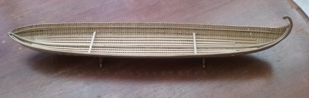
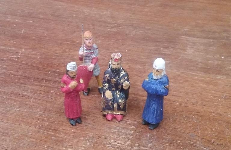
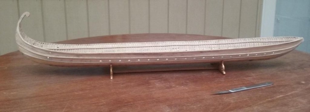
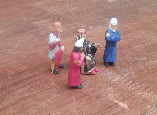
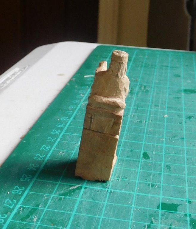
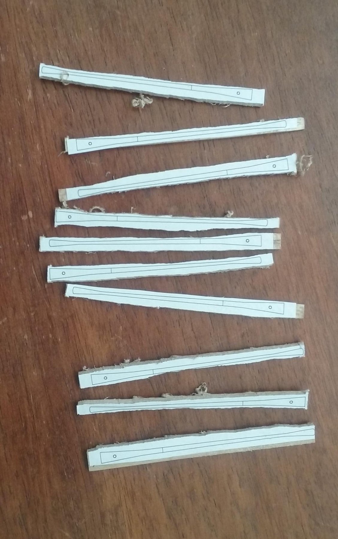
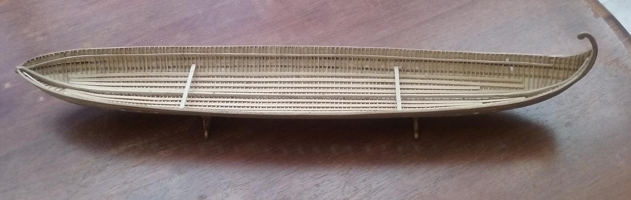
 I haven't updated the log for a while - camera problems meant I couldn't post photos - but I haven't been totally idle. I've cut out all the oarports - the photo was taken yesterday and shows it with a few still to go. Very fiddly trying to get them all the same with the tools I have. And I've made a start on the lower deck oars - here are the first set of blanks I've cut out. The "business" end is as usual, but the handle end won't be visible and I'm experimenting with a shape that can be pinned to the "oarframe" (see photo from two posts ago) and will swivel easily when attached, so I can get the angle of the oars right before I glue it in its final configuration. I don't know why the photos are in the wrong orientation - they were ok when I was working on them. * I've added a beam shelf each side to support the deck beams when the time comes, and I've also added a couple of crossbeams to support the oarframe. And I've completed Emperor Alexios, two of his courtiers and one of his Varangian Guardsmen (I may or may not make a second one - depends on the space available on the poop deck). Next on the list will be making and fitting the mast step(s) and re-fitting the "wings" for the rudders.
-
I thought that was Treebeard . . . Steven PS: Looks like a very nice project to undertake. Good looking boat.
-
Another thought - perhaps the line they followed is a "Great Circle" - a curve joining the ends of a diameter of the Earth - that is the shortest route over the surface f a sphere. I don't have the math to work this out, but it may be a possibility.
-
Two thoughts occur - Both ships may have been staying well clear the coast until they reached the right latitude and then sailed east along the parallel until they reached the coast. Unless I was totally certain of the accuracy of my chronometer I'd be treating the longitudinal calculations not as totally reliable but "more of a set of goideloines". I wouldn't risk the safety of the ship on them unless I had to. The other thing is the prevailing winds. If they are westerly, the coast becomes a lee shore - much to be avoided. Even if they only got occasional westerlies, I'd be staying well away from the coast if possible until it was time to go into port. Steven
-
The cross of St George relates specifically to England - a red cross on a white background. The "Union Jack" - the flag of Great Britain - is a combination of the Cross of St George (England), with Scotland's cross of St Andrew - white saltire (diagonal cross) on a dark blue background and Ireland's Cross of St Patrick (red saltire on a white background) Steven
-
Thanks, Dick. I was originally thinking of getting an old cotton sheet from an op shop, sufficiently worn to be thin enough to make a sail at 1:50. But silkspan might be a better option. Fortunately I have plenty of time to think about it. There's plenty to do to the ship before it becomes an issue. And yes, I think I get what you mean about the bulging. I wish you every success with your cunning plan for the half deck. Looking forward to seeing it when it's done. Steven
-
Good to see you back, Dick. The mizzen sail looks very good. Do you find the silkspan easy to work with? It seems to be the only fabric fine enough to simulate sails properly, and I've been thinking of using it myself when the time comes.. Merry Christmas to you and yours. Steven
-
On further consideration I should also say that there'll be no permanent harm done by loosening off the clamps - you'll just have the sides spring outwards, which can be remedied as above. But before you do, make the temporary clamps so you can push the hull back into shape when it's time to glue in the stringer and the beam shelf. It's best to make them while the hull is still being held "shipshape" so you have a shape to return to. Do as many as you need to, probably at fairly close intervals, and ensure the hull and the clamps are marked to show where each one goes, as the distance apart of the bits of bamboo skewer varies depending on the shape of the hull. Good luck with it. Steven
- 8 replies
-
- 3
-

-
- deformation
- ribs
- (and 1 more)
-
I would advise against taking off all the reinforcements and hoping it will sort itself out. It won't. I had a similar problem - my dromon had bentwood frames which spread outward when I took it off the plug. My idea was to use crossbeams to hold the sides in, but I also had a lot of work to do inside the hull before I could glue the crossbeams in place. So I made some temporary "clamps" out of popsicle sticks and bamboo skewers, rather like your braces, to hold the hull shape while I worked on the rest (see page 9 of my build log - posts from Aug 27 to Sept 7 of 2017). Each clamp was sized to sit in one particular place on the hull (and marked accordingly). The beauty of these things is they are so easy to put on and take off. Your problem is more difficult but I believe putting in more temporary clamps would help a lot. You can take off one clamp at a time to work inside the hull without the hull deforming too much (particularly if you work fairly fast!). And adding the stringer and especially the beam shelf should solve the problem permanently. Steven
- 8 replies
-
- 2
-
-
- deformation
- ribs
- (and 1 more)
-
Maritime figures are a bit thin on the ground in Oz, but it might be possible to "bash" wargaming or model railway figures to look right for your purpose. It would also depend on the period you're portraying. Your 22mm figures would be about 1:83 scale. Railway figures in HO scale (3.5mm=1 foot=1:87) would be just over 21mm tall for a person 6-feet tall, though as I recall, most figures are what they call OO/HO, which is 4mm to the foot (=1:76) so a 6-footer would be be 24mm high. Then there are military figures at 1:72 scale (about 24mm high). But I did find this link https://www.1001modelkits.com/small-scale-soldiers/16329-hat-industrie-hat8098-british-sailors-and-marines-x-80-figures-and-8-naval-cannons-0696957080983.html?iPage=1 and I'm sure there are others out there if you're prepared to look overseas. Steven
-
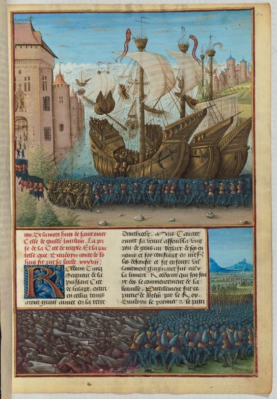
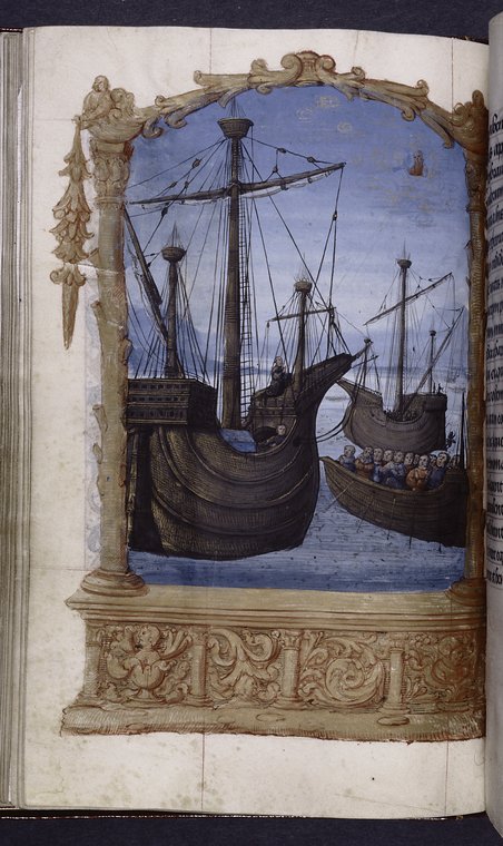
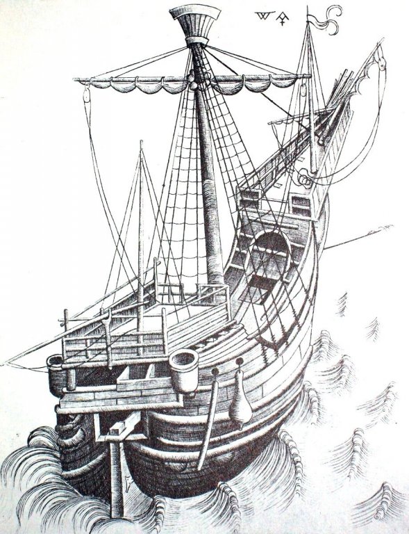
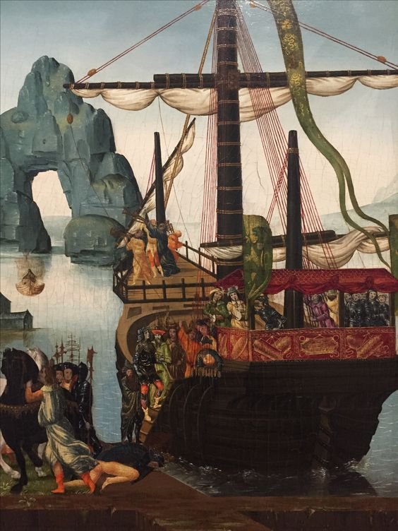
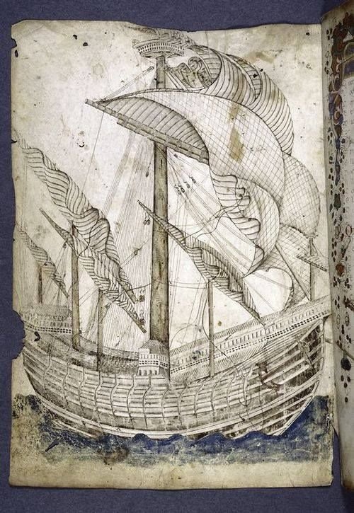
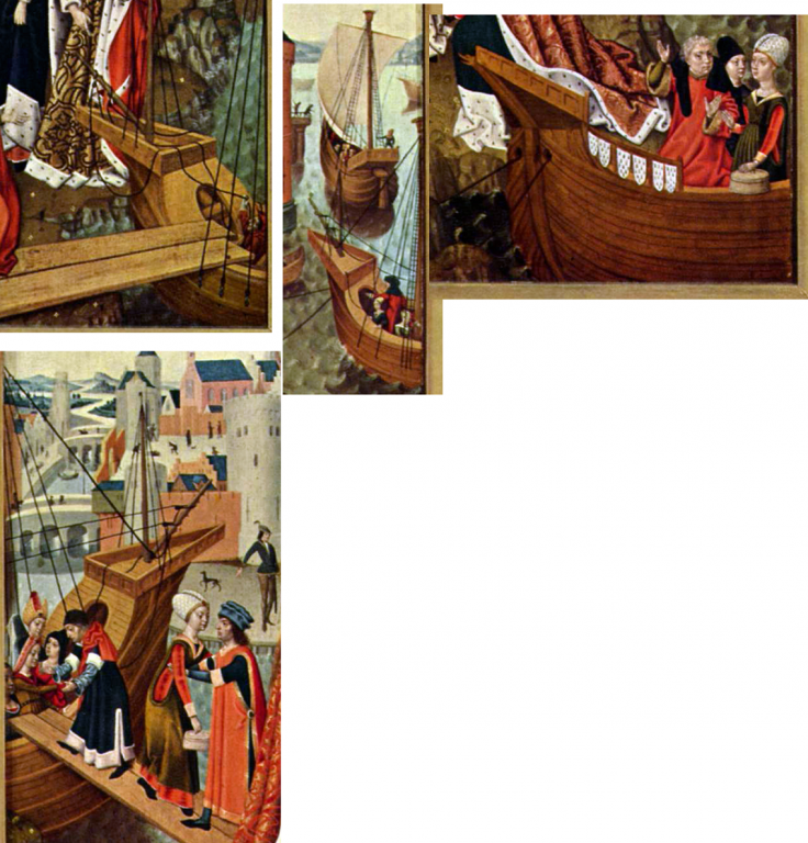
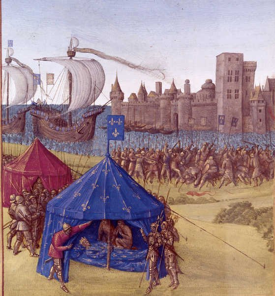
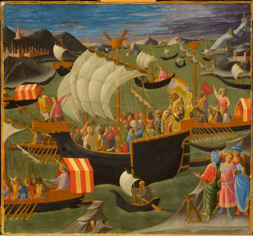
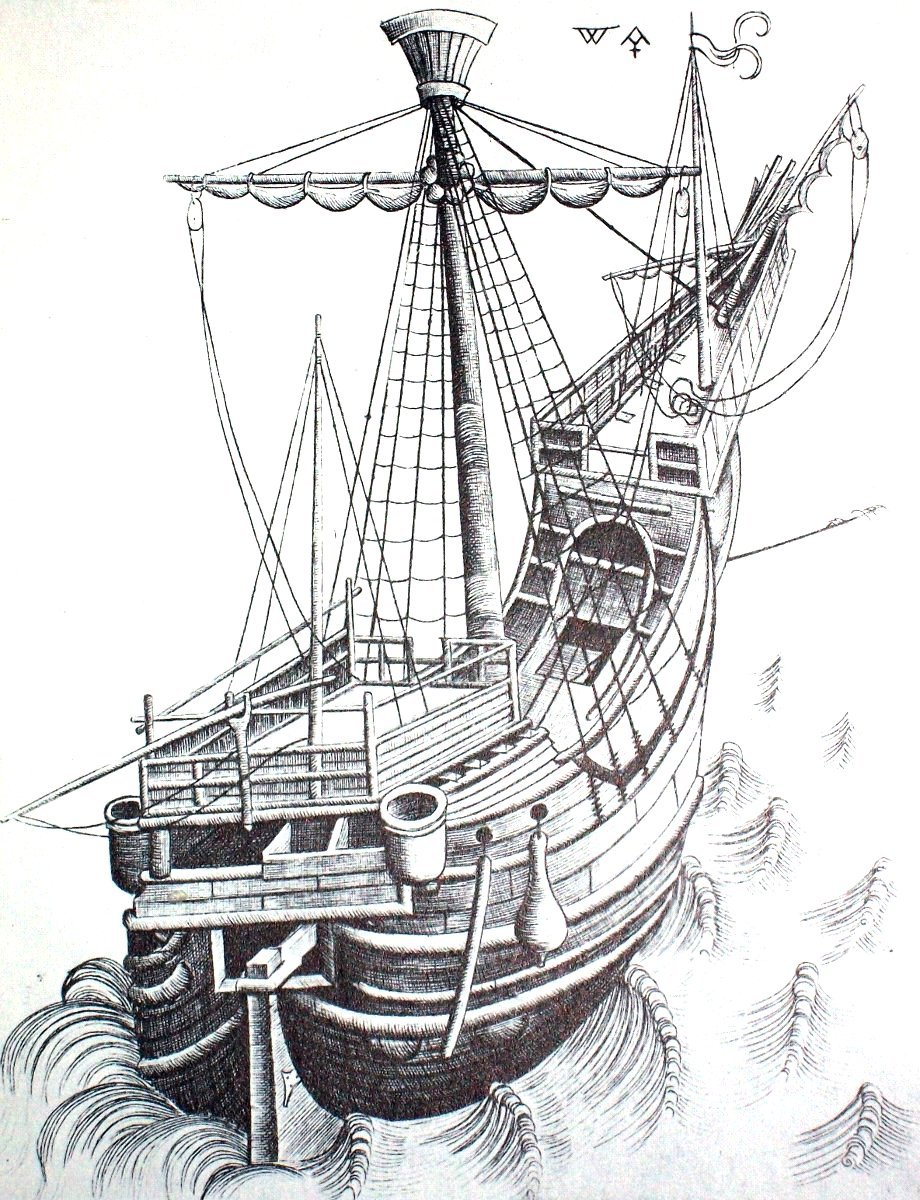
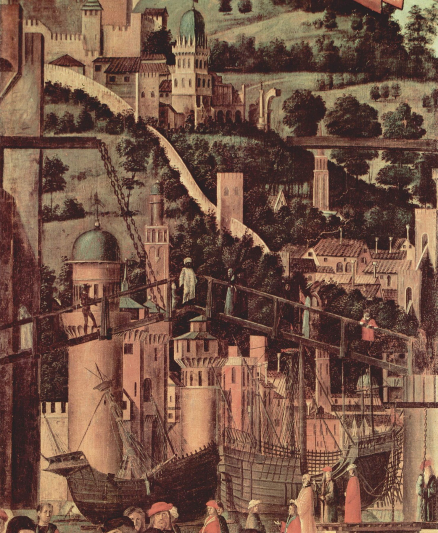
Dick, I got it from Pinterest, a source that is both valuable and occasionally extremely frustrating for its lack of attributions. It is ascribed to Gregorio Dati, a Florentine merchant and diarist who lived from 1363 to 1436, (wikipedia entry at https://en.wikipedia.org/wiki/Gregorio_Dati ) and is apparently held in the New York Public Library, Spencer Collection MS MA 110. It is only vaguely dated (c.1400, which seems to be definitely too early). It could be an illustration from one of his books, but seems definitely later than when they were written. Regarding the strange "stunsails", the have me flummoxed. A very pretty picture, but I have no idea what connection it has with reality. There are several navi tonde (I think that's the plural) with only a single extra mast - the Reixach carrack has a mizzen but no foremast and the picture with the blue tent (above) and the picture immediately above it both show carracks with a foremast but no mizzen. I think you're right to do the mizzen at the very least. As far as I can recall, you built the upper works on the assumption that they'd have to make room for a mizzen mast. It's a beautiful build, I'm really looking forward to seeing her complete. Steven
-
Yes, that makes sense. Perhaps only later did they start thinking of the extra masts in terms of providing extra power rather than just aid in steering. Certainly, as the fore and mizzen masts and sails got bigger the main course got smaller, providing a more balanced play of forces (though that's not necessarily cause and effect). But then how did they mount those slim foremasts (apparently) on the stempost, without the mast just ripping out in the first big blow? Steven
-
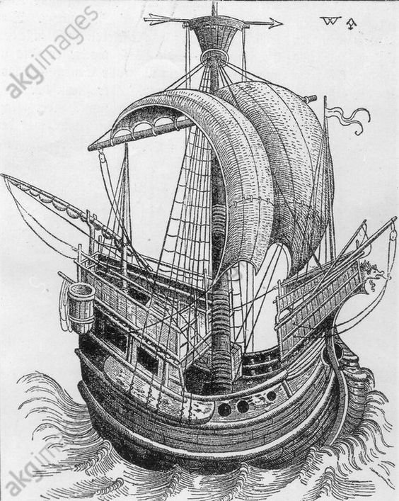
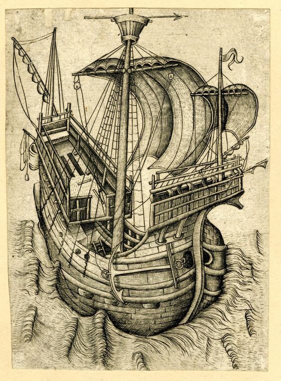
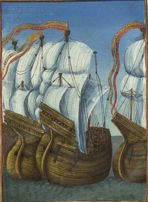
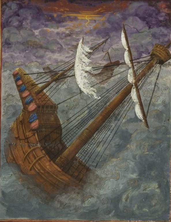
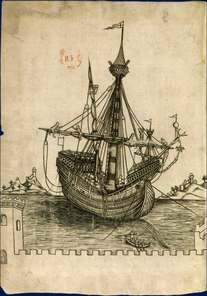
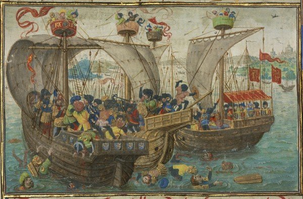
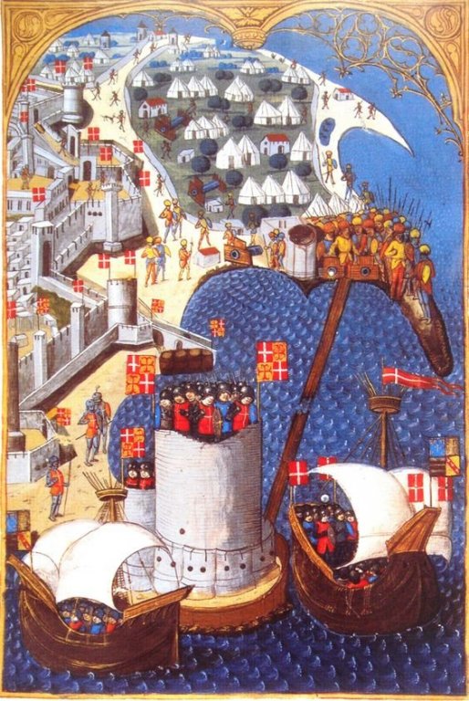
Well, perhaps you're right, Dick. I've collected quite a few contemporary pictures of single masted (and two-masted) "proto-carracks" and though as a general rule the single-masters seem to be somewhat more basic (with less superstructure, for example), there are plenty of exceptions - three-masters with simple superstructure and single-masters with the whole box and dice. And enough from this part of the century - and later - showing what are obviously meant to be cutting edge ships (such as the invasion fleet at Rhodes) with only a single mast. (Note, wherever I've been able, I've included the date and place of the picture in its title - you can see it by hovering the cursor over the picture). Regarding the impracticality of the foremast, I'm not sure where the problem lies, but it seems to me that many foremasts of the time were thin and short and seem to be a bit of an afterthought. As I think you mentioned earlier in this build log, some of them were very far forward - so far forward that they must have been founded on the stempost rather than the keel. One at least is shown off-centre Others were thick and stumpy, and yet others quite respectable masts in their own right. Obviously, the date of the representation is important - presumably the later the picture the more likely the ship is likely to have a foremast, and the more likely it is to be fairly substantial. And a lot of these pictures are several decades after your own representation. However, I think the further north you go, the more behind the times the ships are likely to be - Venice was at the cutting edge of ship design at the time. So a later picture from, say, Flanders, is likely to show what was common decades earlier in Venice. However, consider also that in 1445 at the time of your model, there were quite a decent number of three masters (40% is still quite a few) and that it seems unlikely that the Doge of Venice, who could easily afford the maritime equivalent of a Rolls Royce would content himself with a Corolla, particularly at a time when one's prestige was so dependent on a conspicuous display of wealth. Anyhow, this is all just for your consideration. I'm sure you'll work out something you're happy with and for us all to admire. Steven


.thumb.jpg.e0d965fb66b760f1765ea6d584dae570.jpg)

-
Nice work, Götz. It's taking shape well. Steven
-
Coming along nicely, Robin. Where would we be without balsa? Steven
- 91 replies
-
- 3
-
-
- kolderstok
- duyfken
- (and 1 more)
-
That's beautiful work. What kind of wood was used? Steven
- 11 replies
-
- 4
-
-
- decor
- enterprize
- (and 1 more)
-
I stand corrected, but it's a pleasure to be so. That's really fascinating information, and I suppose after all that furniture would have been regarded as part of a ship's "establishment". Steven
-
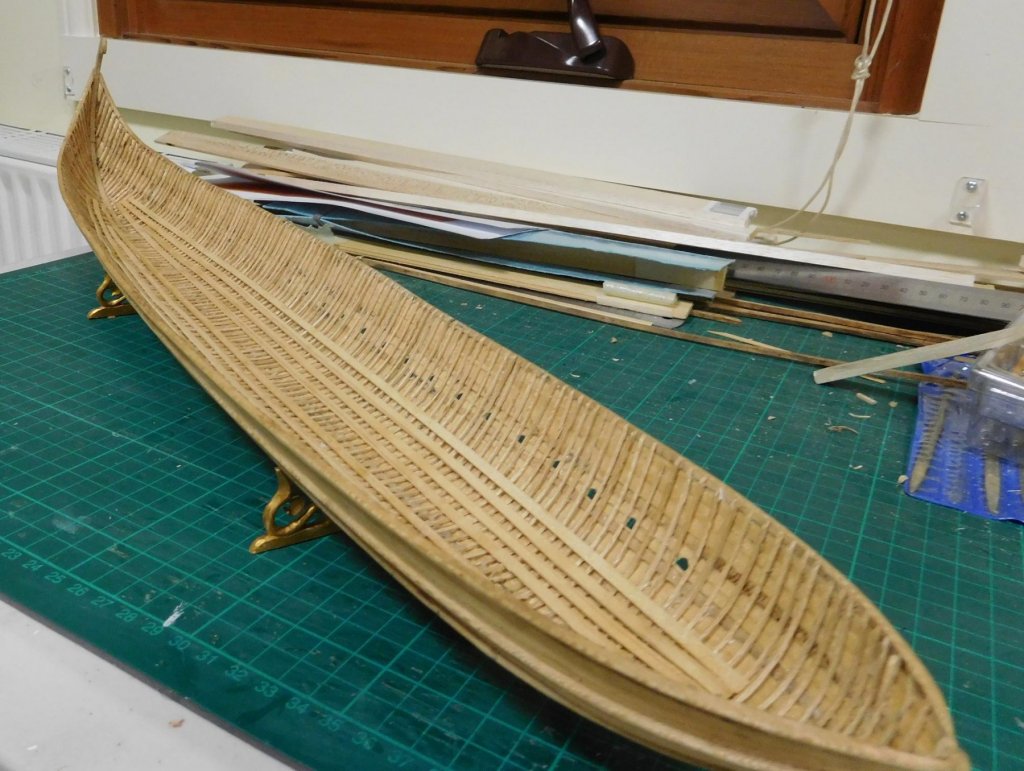
Thanks everybody for the likes and especially thanks Robin. (Of course I got the idea for the "waterline" from you.) Steven PS: My wife also thinks it looks like a basket.
-
Beautiful, precise work, Patrick. This is an excellent build. Steven
- 756 replies
-
- 5
-
-
- galleon
- golden hind
- (and 2 more)
-
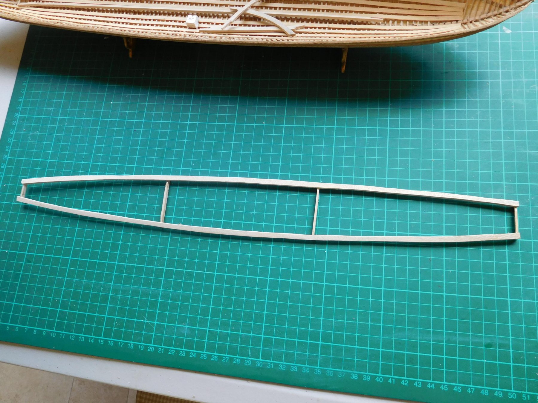
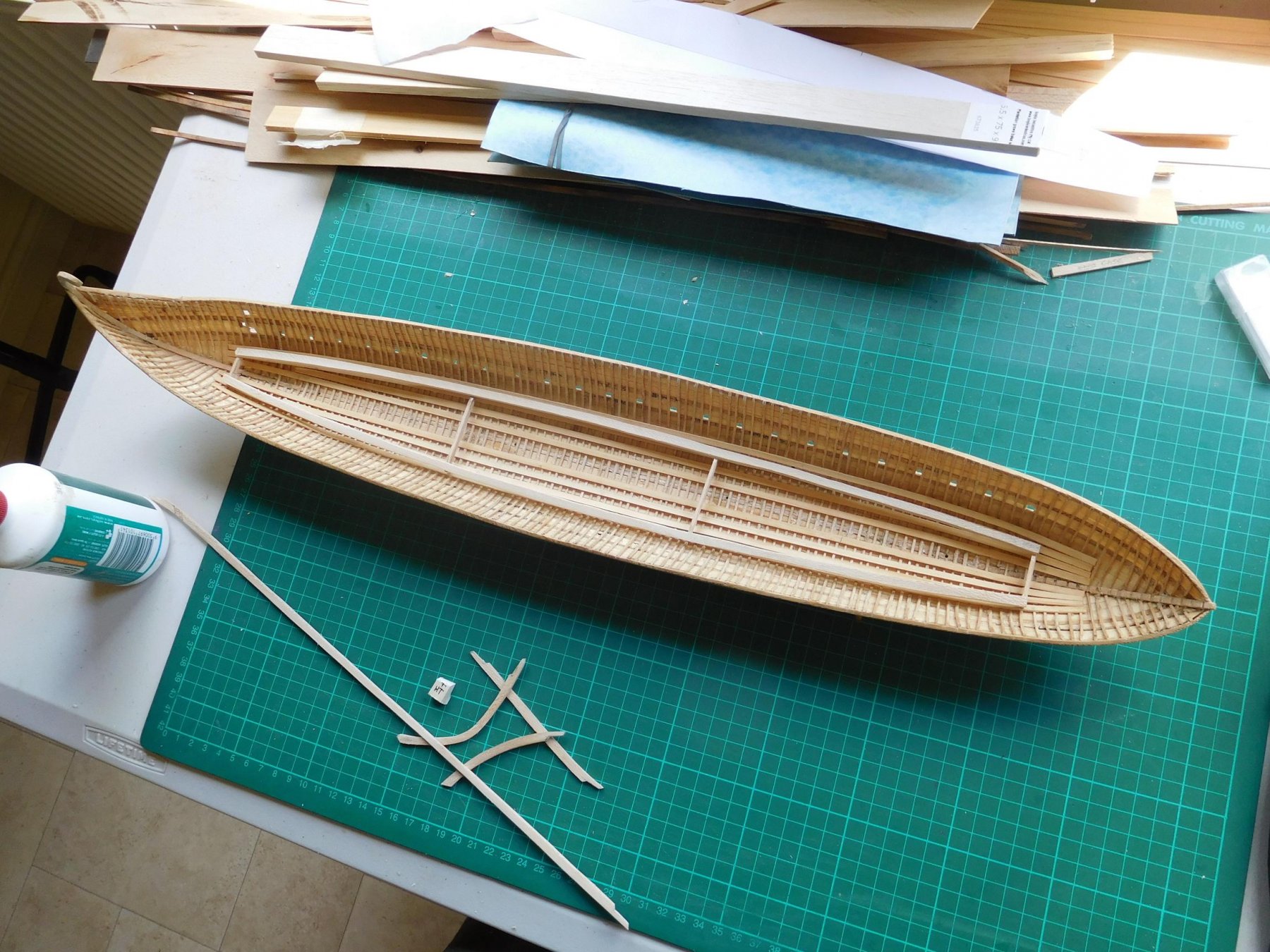
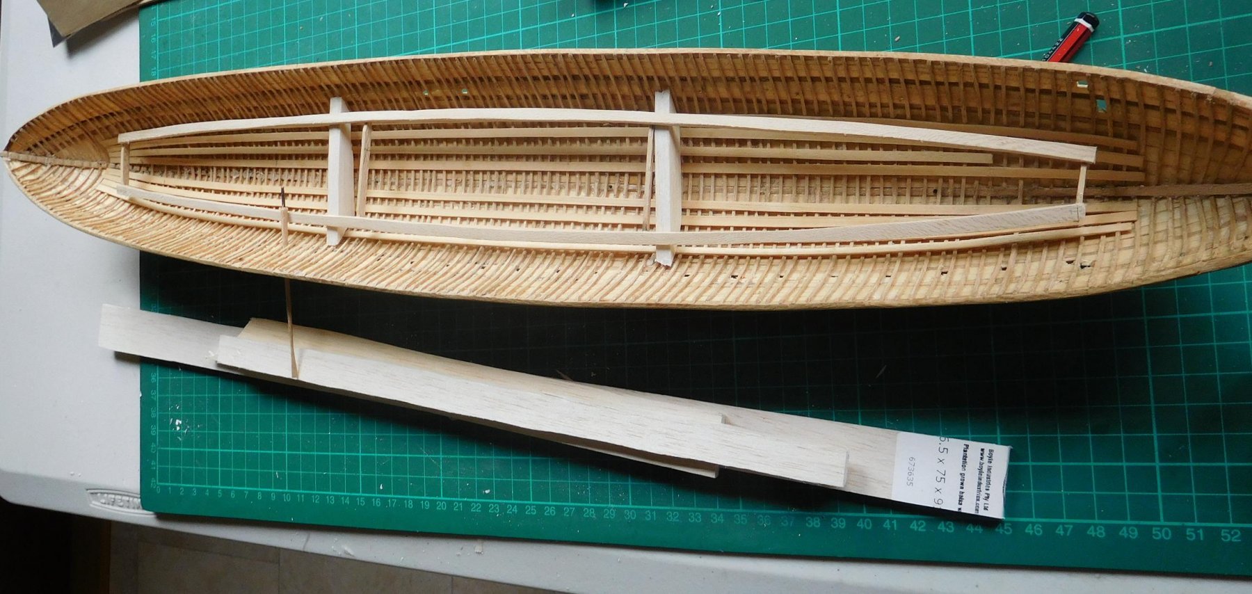
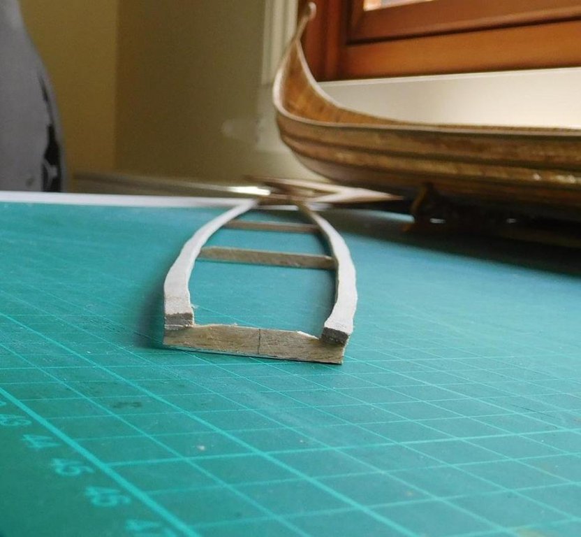
Working on the keelson, stemson and sternson. I've hedged my bets - the masts are supposed to be stepped into the keelson, but I still haven't decided whether I want one or two masts. So I worked out where the holes for the masts should be in a single and dual masted set-up, and bored holes for each and all. From what I can see, the keelson in this model just isn't thick enough for a large enough hole for a mast step, so I'll probably fudge it and make a more substantial step to be sure the mast(s) are properly supported. It'll all be invisible below decks anyway, so I'm not going to get too concerned. I'd rather have the masts properly secured than have an accurate (but inadequate) step which nobody can see. Interestingly, the contemporary Byzantine texts talk about ships' masts unstepping themselves in a heavy blow, and maybe now I can see why. I didn't have a long enough straight enough piece of wood for the full keelson so I've scarphed two pieces together, and also made scarph joints for the stemson and sternson. I think I'm getting better at scarph joints . . . Here they are dry fitted to each other: And some progress on the support frame for the lower bank of oars. I've spent a lot of time agonising about how to do this, and it looks like I've come up with an answer that will work. A frame that follows the curve of the hull, far enough inboard of the sides to allow for the inboard section of the oar-looms. To get the vertical angle right I made up a temporary support at water level and rested the oar blade on it. This then determines how high the oar handles have to be, and so where the top of the frame should be. Once I figured that out I made temporary supports out of balsa to support the oars at the right height, and these will be replaced in due course with a permanent frame. I also angled the sides of the frame so the oars would rest along its surface, rather than just touch at a point. Viewed end-on the curve isn't as smooth as I might like it to be, but this will all be invisible - this frame is purely functional - it never existed on the real ship. The idea is for the outboard part of the oars to be properly oar-shaped, but inboard they'll be flat in section and each one pinned to the frame with a small brass pin which will allow them all to swivel, so I can move the frame forward and aft till I get the horizontal angle right. I've cunningly decided to have the oars at the end of their stroke - that's to make it easier for me to make the upper oarsmen, as then their arms will be right up against their chests rather than extended, and that will make it easier to carve and cast them. Steven


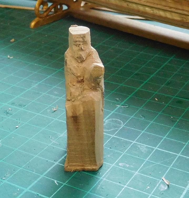
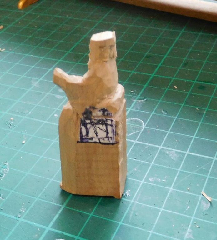
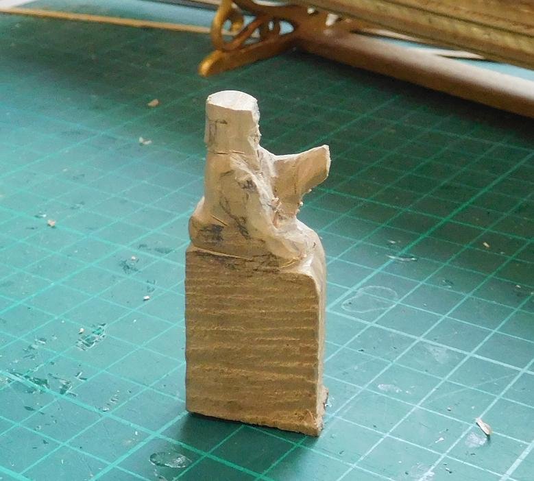
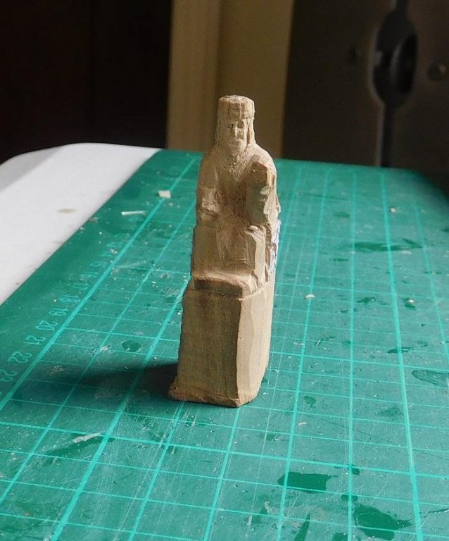
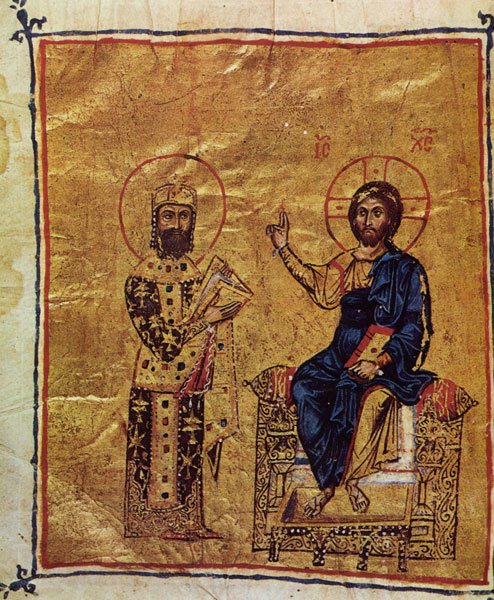
-
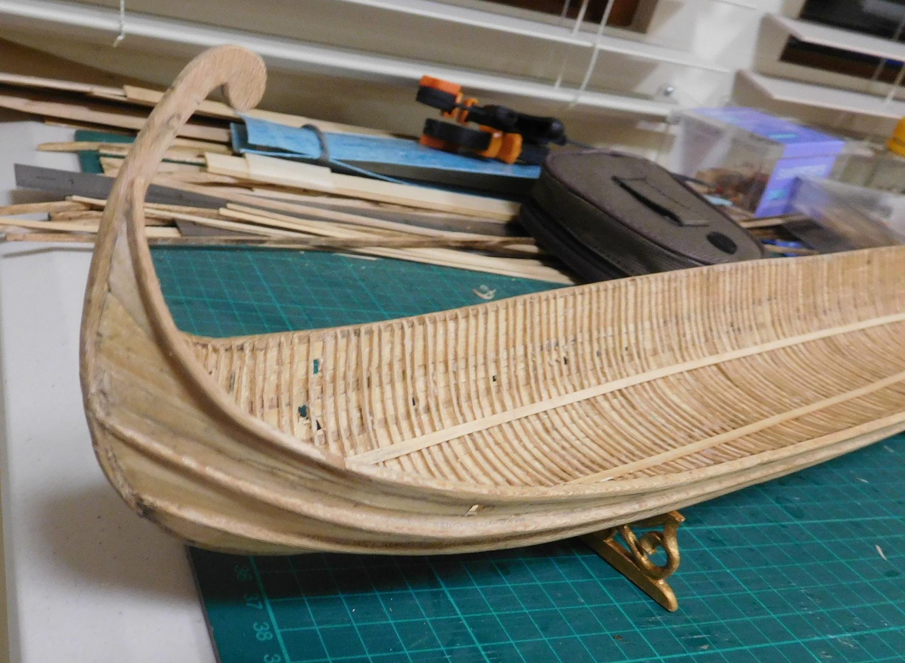
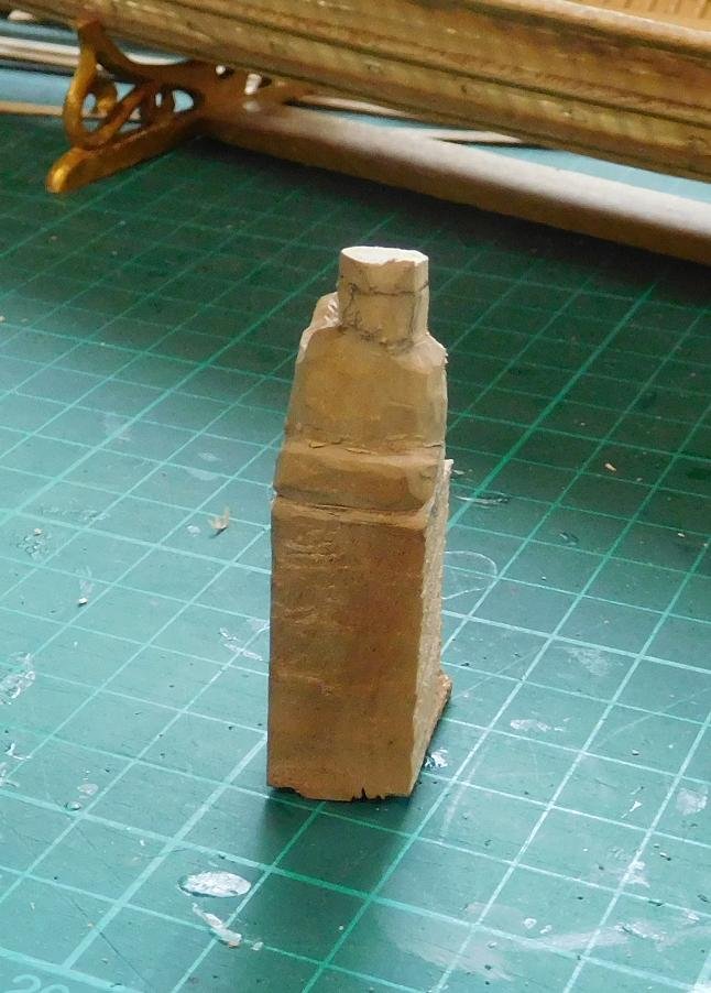
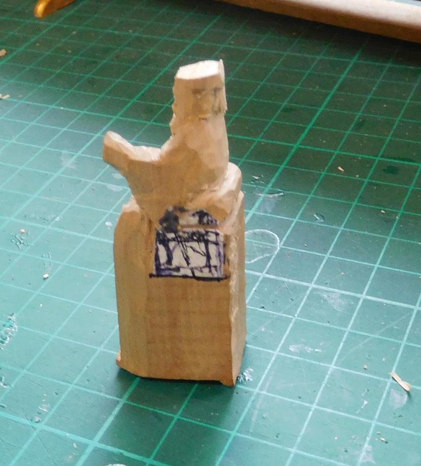
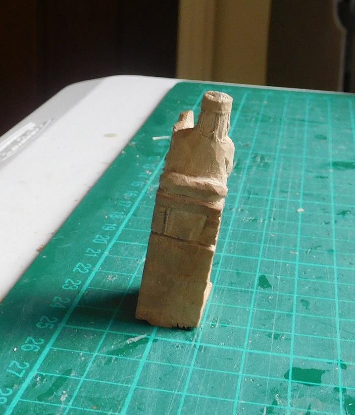
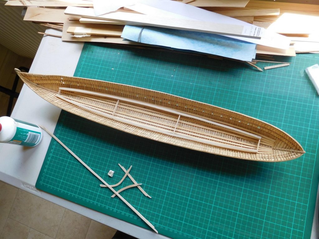
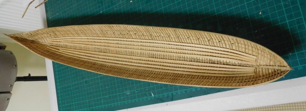
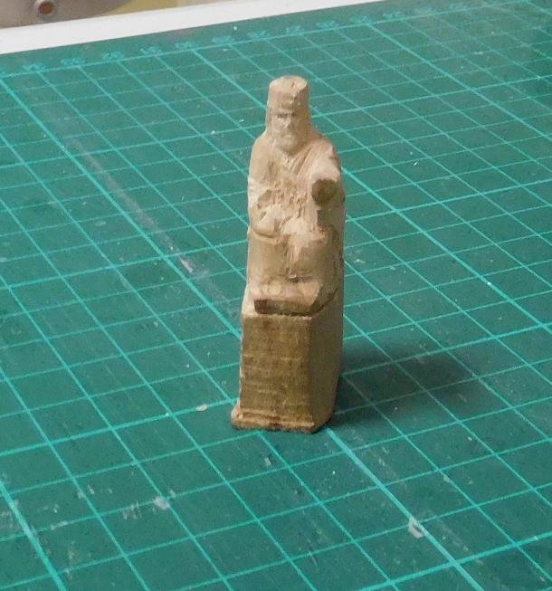
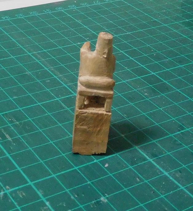
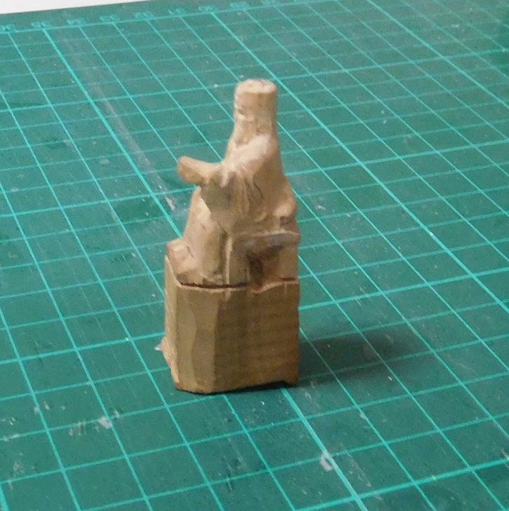
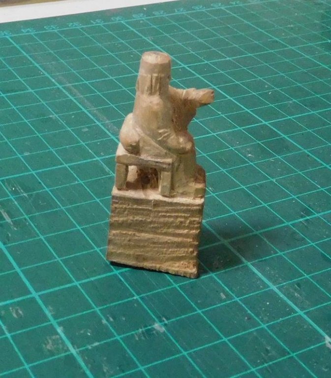
The repairs to the planking are now complete: I think I'll extend the gunwale up to the pencil line on the tail, which is how it was before the disaster. I think it will look better. And the stringers are all in place. They look quite a bit better than I'd expected. And I've been back to the figure carving in between times. This is the VIP passenger - Emperor Alexios Comnenos, who I chose because he was the one who initiated the use of fearsome animal heads to shroud the "business end" of the Greek Fire projectors, adding to the shock and awe. Early stage -roughing out, which I call the Megatron stage - (look at his face) He's sitting on a "portable throne" with a bolster behind him, which appears over and over again in contemporary representations. They were gilded and very ornate. Here is a contemporary picture of him, with Christ sitting a throne of this type, though the one I'm making has four fairly hefty legs - also a common feature. Hmm, I'll have to make a footstool as well. I'll try to reproduce that as best I can at this scale. Next stage - finer shaping Next stage - nearing completion Still quite a bit to do on him - smoothing off and trimming etc. And of course painting. My faces are getting better, but I just haven't been able to capture the slightly rogueish expression on his face. My next project will be to make the framing to support the oars of the lower bank below deck level, standing in place of the oarsmen themselves. Steven


-
Hi Michael, Beautiful work. The march of archaeological progress can be a real problem - it can turn what we "knew" on its head. A model based on this can only be accurate to the best knowledge to date - subject to further discoveries. I am in awe of anyone who completes a ship model as complex as this, and you've done an amazing job of her. By the way, regarding the Viking shields, you might be interested in this link. The Gokstad ship's shields alternated - one plain black and one plain yellow shield, then black, yellow etc. The black was probably charcoal with some kind of binding substance (I experimented back in the day with animal fat - it works well, but attracts files like you wouldn't believe), and the yellow is though to have been arsenic sulphide. Unfortunately, conservation techniques when she was discovered were not what they are now, and no trace of the pigment survives. Steven
-
SUCH a pretty ship. I went on board the replica while she was still a-building, and still have the little oak off-cut with her name burnt into it with a branding iron. I'll be following the build with interest. Steven
- 91 replies
-
- 4
-
-
- kolderstok
- duyfken
- (and 1 more)
-
Just guessing here, but I think it would to a certain degree depend on the Captain's finances - a well-off captain would probably provide his own furniture and it would most likely be in the fashion of the day (there should be lots of images on the Net if you do a google search), though unless he was very wealthy, I'd expect it to be a relatively plain version of that style. If he wasn't well-off, the ship's carpenter would probably make it for him and it would be VERY plain. Steven


.jpg.349d31a9e065812de88067b0ce5c4bc8.jpg)