GuntherMT
-
Posts
2,213 -
Joined
-
Last visited
Content Type
Profiles
Forums
Gallery
Events
Everything posted by GuntherMT
-
I don't know that they are eye-splices, it's really impossible to tell from that picture and the fact that they are served over with the white section. As far as dead-eyes, they would still be needed with steel, unless there was some other method of adjusting the shrouds, since even steel expands and contracts with weather, just not as much. I suppose they could use turnbuckles or something, but the lanyards and dead-eyes are what they have.
-
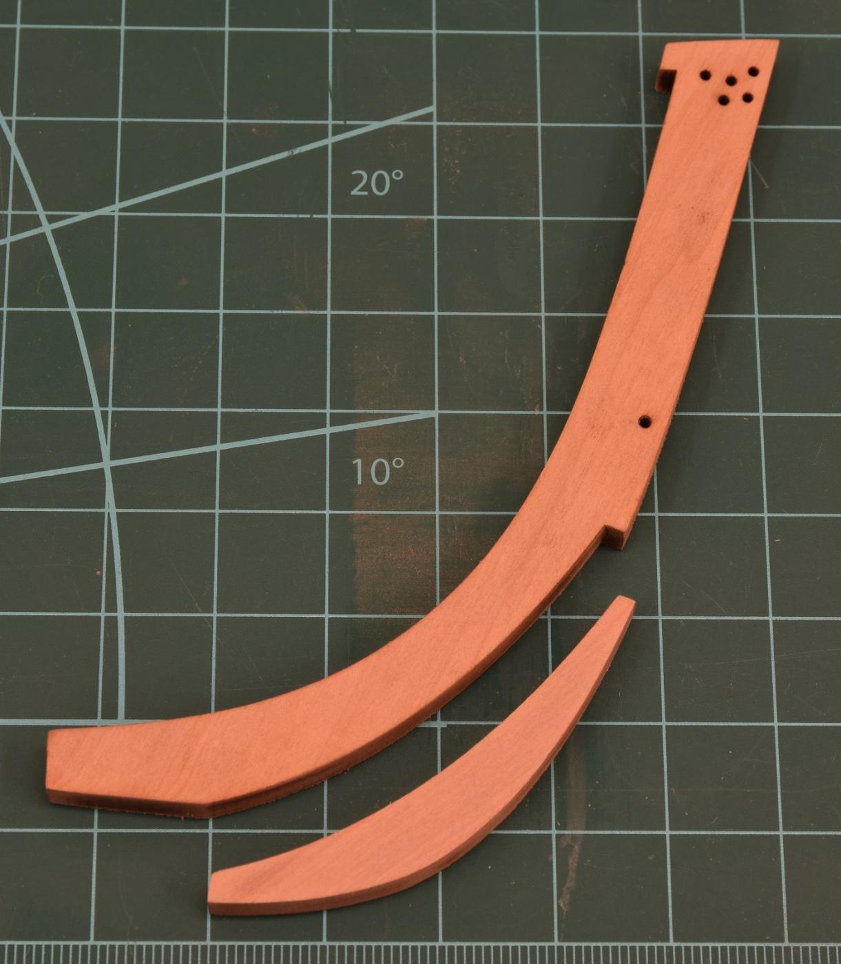
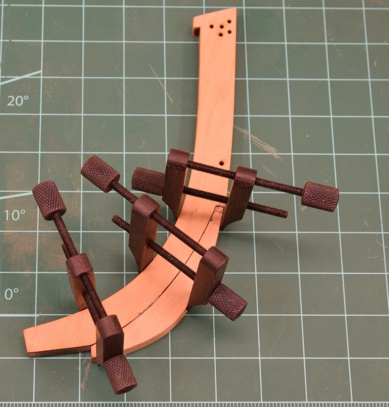
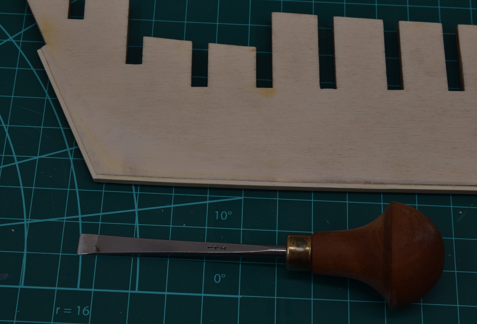
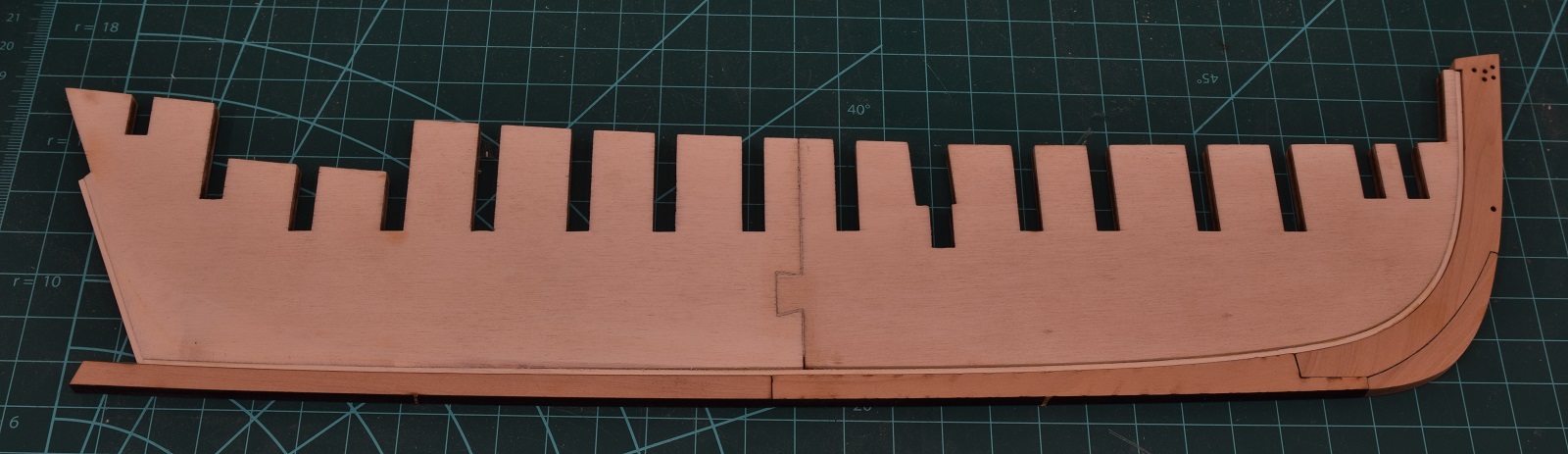
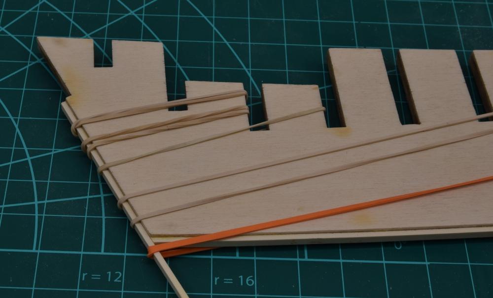
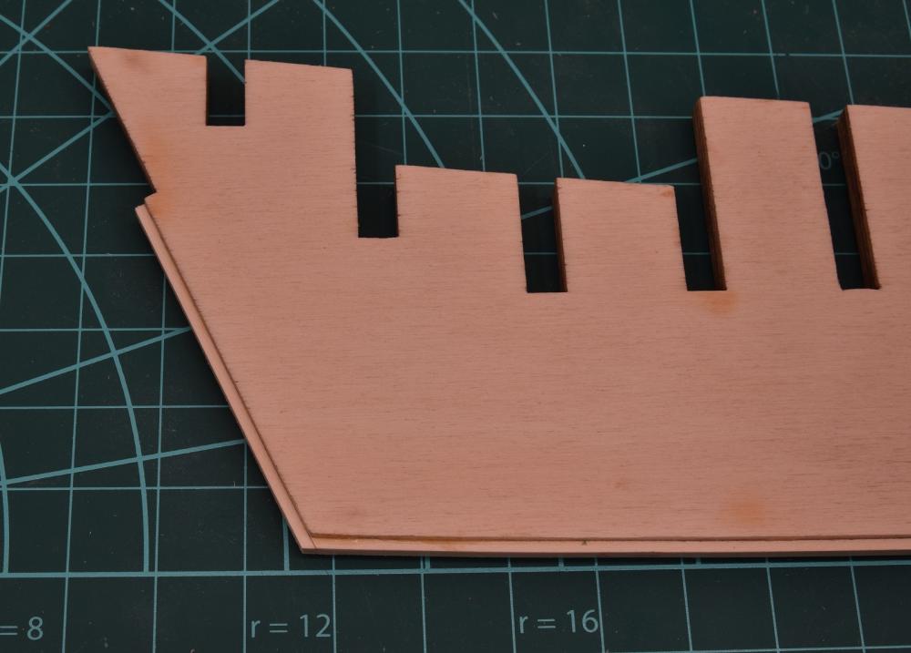
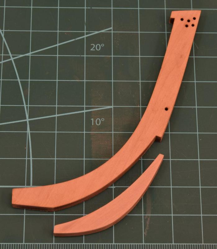
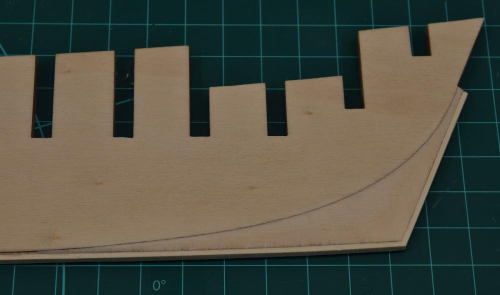
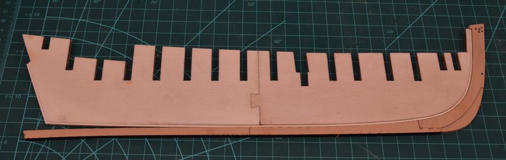
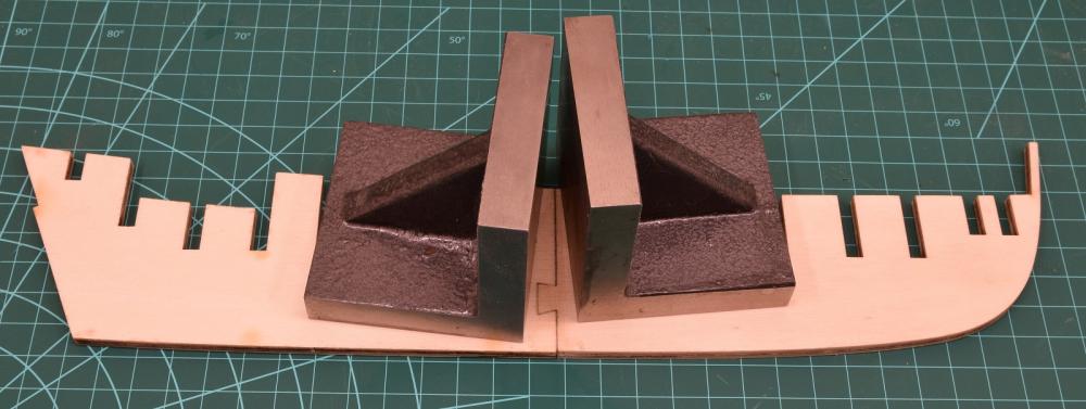
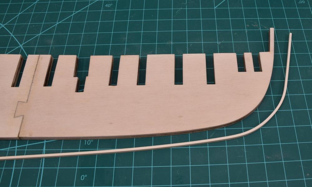
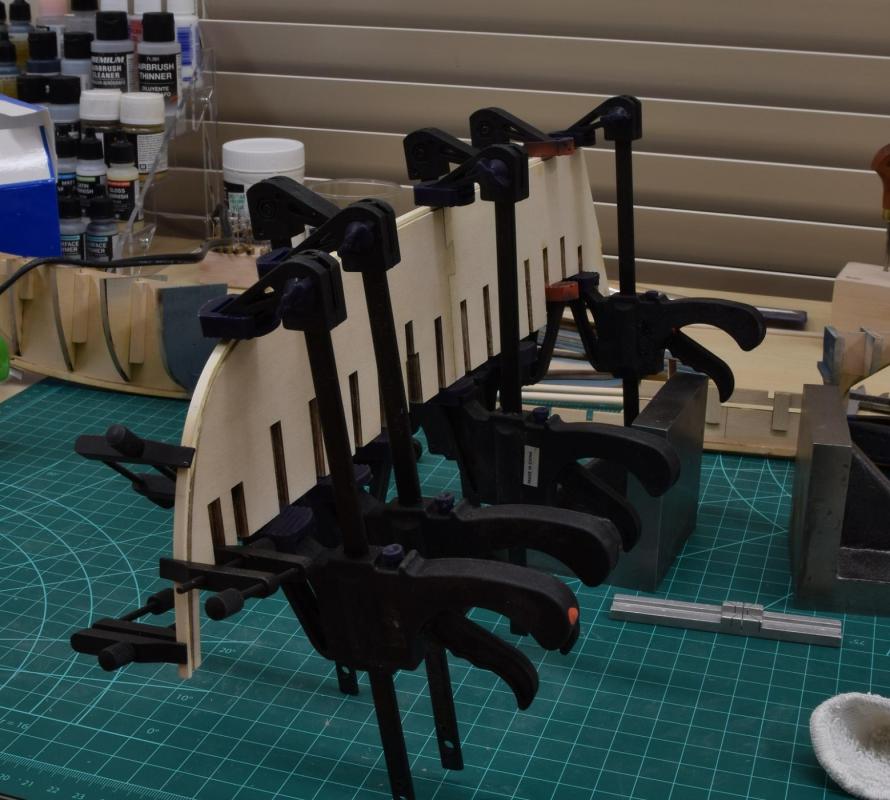
On we go, with another small update and a bit of progress on the Cheerful. First I completed the rabbet strip at the stern. Next up I cleaned up the laser-cut boxwood parts that form the stem, and glued them together. Frank showed me these clamps that he used from Lee Valley so I ordered some for myself. They are really great little clamps and I believe they'll be seen a lot during my build logs! Next up, I transferred the bearding line to the side of the former that didn't have the line laser-etched into it, and then using a chisel and some sand paper I did the beveling at the stern from the bearding line to the rabbet strip. Not sure it's perfect, but it's as good as I think I'll get it, and I believe it should work fine. I really didn't accomplish anything else yet, but I did dry fit the keel parts to verify that things are tracking good for a nice fit. From that photo, and indeed from looking at things in person, the appearance is that the keel is pretty flat. However, flipping the aft portion of the keel over so that it is upside-down reveals the truth! Hopefully I will have time tomorrow to complete the keel and the tree-nailing that goes into it, and get it glued up to the former, after which I can start looking at the bulkheads. Thanks for all the visits, likes, and comments everyone, and see you next time, whenever that is!


-
Looking great! My personal opinion of what looks best is to fully rig the tackles except for the inhauls, which is something that depends heavily on deck space I believe. There was simply not enough room on the deck of the AVS to place inhaul tackles because of the deck layout. The big caveat here is that the blocks and ropes need to be appropriately sized, which often isn't the case with the stuff supplied in the kits. I downsized all of my gun tackle (rope and blocks) to an appropriate size and I love the way the rigged guns look on models when done properly. I agree with Mike that the eye-bolts should be placed regardless of whether you choose to add the inhauls or not.
- 2,191 replies
-
- 5
-

-
- confederacy
- Model Shipways
- (and 1 more)
-
No point in even going with Amazon unless it's just more convenient for you since Ken posted a link to the US distributor which ships for free in the U.S. http://www.hobbyzone.biz/psm01.shtml Edit: Actually it's $100 on Amazon with free shipping, vs. $65 direct from the distributor with free shipping.
-
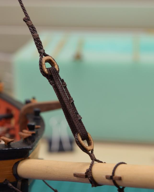
I won't guarantee that it's correct, but according to the plans, a practicum, and everything else I could find when I rigged the AVS, they are rigged wide-end to wide-end, so the narrow end of the lower block would be the closest end to the bowsprit. Like this:
-
For cleaning of small files, I use a fine brass brush: http://www.amazon.com/Wood-Handle-Metal-Brush-Brass/dp/B0058ECDGC?ie=UTF8&psc=1&redirect=true&ref_=oh_aui_detailpage_o05_s00
-
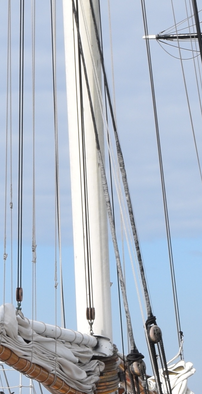
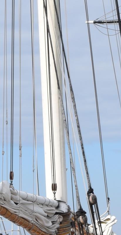
After reading the other America log, I saw how the shrouds on the America were partially white, so I dug through my pictures of the replica in San Diego, and indeed the lower portion of the shrouds were (at one point anyway) white colored. They are also attached quite a bit differently than the drawings and photo's I posted. Unfortunately I don't have any super-clear photo's of the shrouds above the dead-eye, because it wasn't something that occurred to me to photograph in detail. Here is about the best I found, but it clearly shows the white portion and being served, and you can also see that it's not secured using the seizing system, but rather appears to be eye-spliced and served back over completely, very similar to what you are already doing, except white all the way down to the dead-eye, but not around it.
-
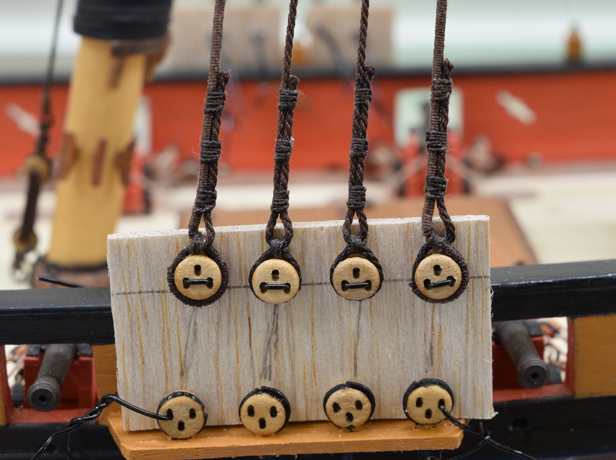
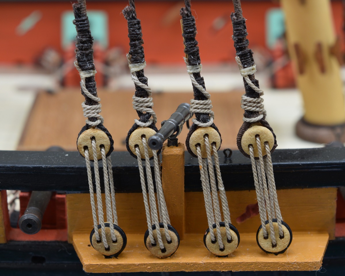
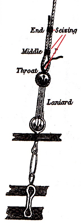
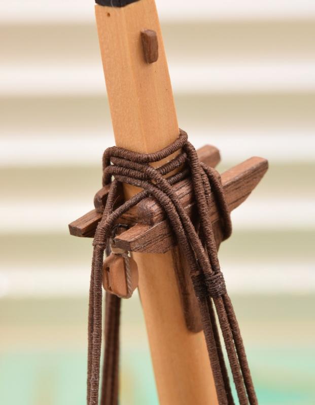
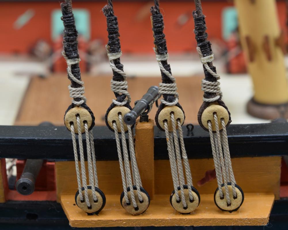
So it looks like you are getting the hang of the machine, but I don't think you quite understand how the serving was done vs. the seizing. The entire length of the shrouds that would possibly be in contact with a sail would be served, and that served rope wrapped around a dead-eye and then seized at the bottom, and at the top it would wrap around the mast and come down as the next shroud (the shrouds would be laid in pairs unless there are an odd number). On the shrouds not in potential contact with a sail the serving would end a short distance below where it wraps around the mast. The seizing above the dead-eye was not a solid 'serving' like you are showing it, rather two or three small seizings spread along the distance of the overlap. Here are a couple of drawings showing the details of the seizings above the dead-eyes. In the second drawing, the red arrow is pointing to the end of the lanyard, which is tied off to the shroud with a small seizing also. The served shroud itself would be a dark color due to the fact that it is standing rigging and would tend to be tarred. Here are mine prior to adding the lanyards and cleats that tend to make it unclear where one seizing starts and another begins. Note that I did not leave enough of a gap above the dead-eye for my lanyards to pass through later, so my lanyards are not properly rigged like are shown above in the 2nd drawing. Also, you can see that the fore and aft shrouds are fully served (I should have served them all the way to the end wrapping around the dead-eye, but I screwed that up and chose not to re-do them), but the inner two shrouds are not served at all on the bottom, only at the top where they wrap the mast, as seen here (you can also see the single seizing to tie the 'loop' together after it wraps around the mast. The serving for the middle two shrouds ends just below this photo. The lanyards would not be tarred, as they had to be adjusted, so the lanyards and the seizing for the lanyard would be tan rope. There are shroud cleats on the inside of all 4 shrouds, which is why there is so much seizing above the lanyard seizing here, as each cleat has three separate seizings holding them to the shroud right above the lanyard seizing. Ultimately, you can do it however you think it will look the best, and if I'm completely misunderstanding what you are going for here, then I apologize, and can remove everything here to un-clutter your log any time you want. Edit: Due to how more modern the America is vs. the reading I've done, all of this could be completely wrong too! If so, let me know and I'll remove all of this. Take care,


-
It's looking good Greg, and I'm with Dave on this - there is no real reason to work hard to avoid drop planks or stealers, as they existed on real ships too, and I also tend to think they look cool when well done. I don't know the exact count like Dave does, but I know for a fact that I used both drop planks and stealers in both my first and second planking layer, and I think it came out pretty ok.
-
Fantastic looking work, as always. Hope it's travel-worthy for the next meeting.
- 649 replies
-
- 5
-
-
- dunbrody
- famine ship
- (and 2 more)
-
Welcome aboard everyone. Not a stupid question at all, as this is the only model I've ever seen use this method. In most models you have to carve a rabbet into the former (false keel) either before or after attaching the keel (or some combination). This rabbet strip sits between the keel and the former, giving you a ready made rabbet all along the keel. At the stern the former is shaped down to the rabbet strip from the bearding line, and everywhere else the edge of the former will be angles appropriately for the planking as it's done if I understand it correctly. I've got to read through that section and look at the other logs a few more times before I get there. If you look at Chuck's build log in the scratch section, you should be able to see how he did this. It's really a pretty cool idea. Mark - hope you can make it, I do plan to be there.
-
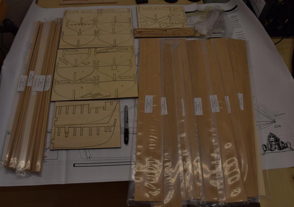
Here is the package that got me into this mess, the plans, all the mini-kits from Chuck, the wood from Crown, and of course the former and bulkheads laser cut from Chuck. I found very early on that I'm going to need to acquire some tools that I don't currently own (like a scroll saw) in order to go too deeply into this build, so it will be interesting to see how far I can get down the rabbit hole before getting more toys. I started by gluing the two parts of the former together after cleaning up most of the laser char. After it was glued I discovered that a bit of one of the pieces was warped a bit, so I used heat and weights to straighten it out over a period of about 3 days. Once I was happy with the former I used a piece of 1/16 x 1/8 holly strip that I had on hand for decking for a future project to shape the rabbet strip along the bottom of the former. Again using heat, I pre-bent the strip to mostly fit the former, so that it wouldn't gap when clamped. I then glued the rabbet strip in place. And that's where I am today. Next I can start on the keel parts, which are laser cut, so require some cleanup before assembly. As with the Picket Boat, this log will likely progress very slowly due to a limited amount of time that I have available to work on ship building currently. Also, needing to get a scroll saw.

-
Greetings everyone, and welcome to my first 'concurrent' build log, as I begin the semi-kit (or semi-scratch, depending on your point of view) build of the revenue cutter Cheerful, from Syren Ship Model Company (Chuck Passaro). I've chosen to place this log in the kit build section, since I am using laser cut parts from Syren for the 'back bone' - the former, keel, and bulkheads, as well as all the mini-kits that are available for the ship. This log is starting due to a set of materials that were put on sale in the trade section of this website, and I couldn't resist grabbing it, even though I have far too many kits on the shelf right now. Included in my purchase was everything that Syren produces for this ship except the new pump kit, along with what was apparently a custom wood order from Crown Timberyard with a Holly deck package and boxwood planking strips. As with my other current build log, the Picket Boat #1, this first post will be primarily for an index. The actual log begins in post #2 to follow. Section 1 - Constructing the backbone (former, keel, bulkheads). 1. The beginning - the former (false keel). 2. The keel. 3. Bulkhead start (side trip - beginning the windlass). 4. Bulkheads all on (side trip - windlass part 2). 5. Gunport sills - starboard side.
-
Good looking hull. I've never done a solid hull, but they look harder to me than a PoB build. Nice job.
- 701 replies
-
- 3
-
-
- phantom
- model shipways
- (and 1 more)
-
And in my opinion, having used both, they are worth every penny.
-
You have discovered one of the super easy and obvious ways to improve the looks of your completed model! Another super easy way (and makes the rigging easier as well) is to replace the kit provided rigging line. Every kit I've gotten so far has terrible rigging line and typically not in proper scale. I replaced all of my line even on my very first model with Syren line, and I don't regret a penny spent on that.
-
I somehow let this build fall off my radar near the end of December, so I just caught up. Fantastic build Danny, just gorgeous work all around.
-
Guess I didn't put that Greg. Yes, the Cheerful.
-
What is better than one really slowly progressing build log? Why TWO really slowly progressing build logs of course! Coming soon to a forum near you, because I'm dumb and can't wait to start working on this... When I start this it will be in the Kit sub-forum, as the general consensus I've seen in the discussions surrounding 'kit vs. scratch' comes down to making your own keel/bulkheads or frames, and I'm using the laser-cut pieces for this very important part of the construction.

-
Looks like you are getting the right idea, and it's coming along nicely. Two things to keep in mind based on your description of how you are doing this. 1) If you place the plank while it is still damp, it will have some shrinkage as it dries. This will possibly cause small gaps to appear between planks. To avoid this, make sure the plank is completely dry before you place it. 2) You don't mention beveling the edge of the planks. Due to the curve of the hull, the edge of the plank that is going up against the already placed plank should have a bevel sanded into it to close the gap that will naturally open between the planks due to the angle between the planks. I thought I had a drawing of the plank edge beveling, but I can't find it at the moment, so if what I said isn't clear, please let me know and I'll try to clarify it.
- 79 replies
-
- 9
-
-
- lady nelson
- amati
- (and 2 more)
-
Sent you a PM a while back Kurt, did you ever get it?
-
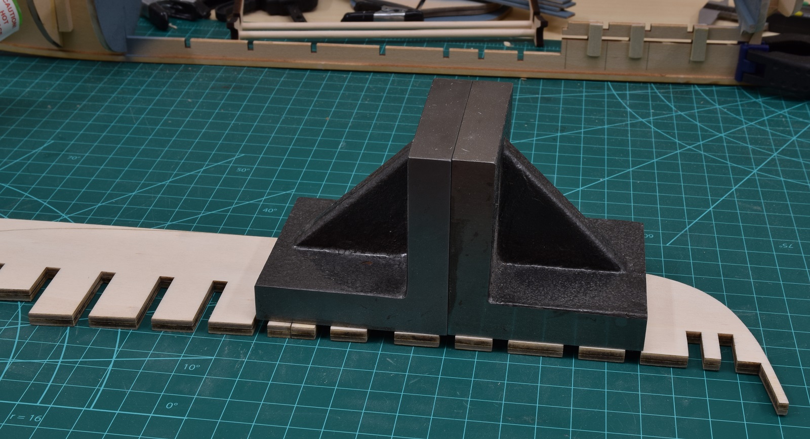
Those scores are exactly what you guessed at, they are planking marks. This model has a planking plan, and the edges of the bulkheads are marked for exactly where the edge of each plank should lie.