ccoyle
-
Posts
10,528 -
Joined
-
Last visited
Content Type
Profiles
Forums
Gallery
Events
Everything posted by ccoyle
-
 It's a very old Monogram kit, first released in 1956. https://www.oldmodelkits.com/index.php?detail=3543&page=74&soldarchive=1
 -
It's worth mentioning that this kit is also available as part of Shipyard's "laser cardboard" series (translating Polish to English sometimes produces odd-sounding terms). The laser cardboard kits are complete projects in 1/72 scale that include kit, frames, blocks, rigging material, paints, and glue. But they are not cheap -- the Mercury kit sells for north of $400.
-
I probably shouldn't have looked at pictures of actual Hellcats just now, because now I'm seeing that the scoop on the model is all wrong, but I swear that's the best I could come up with based on the diagrams, and I can't see how it could have been done differently with the parts on hand. 😕 I swear my next airplane will be either a Halinski or a Kartonowa Kolekcja kit,
- 150 replies
-
- 14
-

-

-
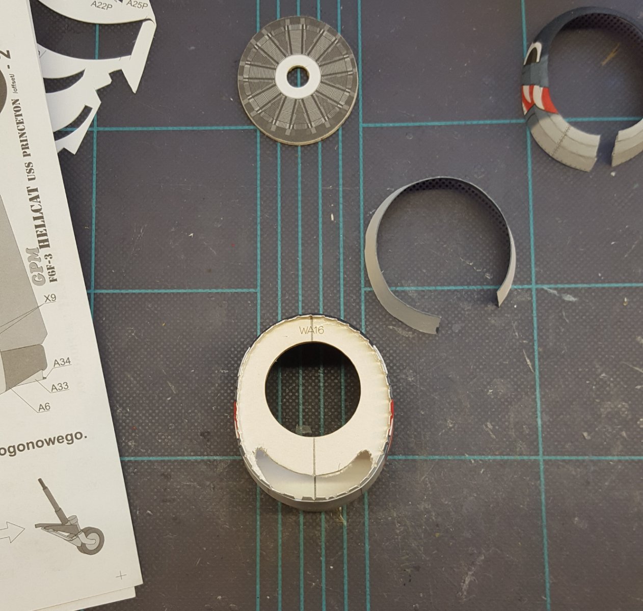
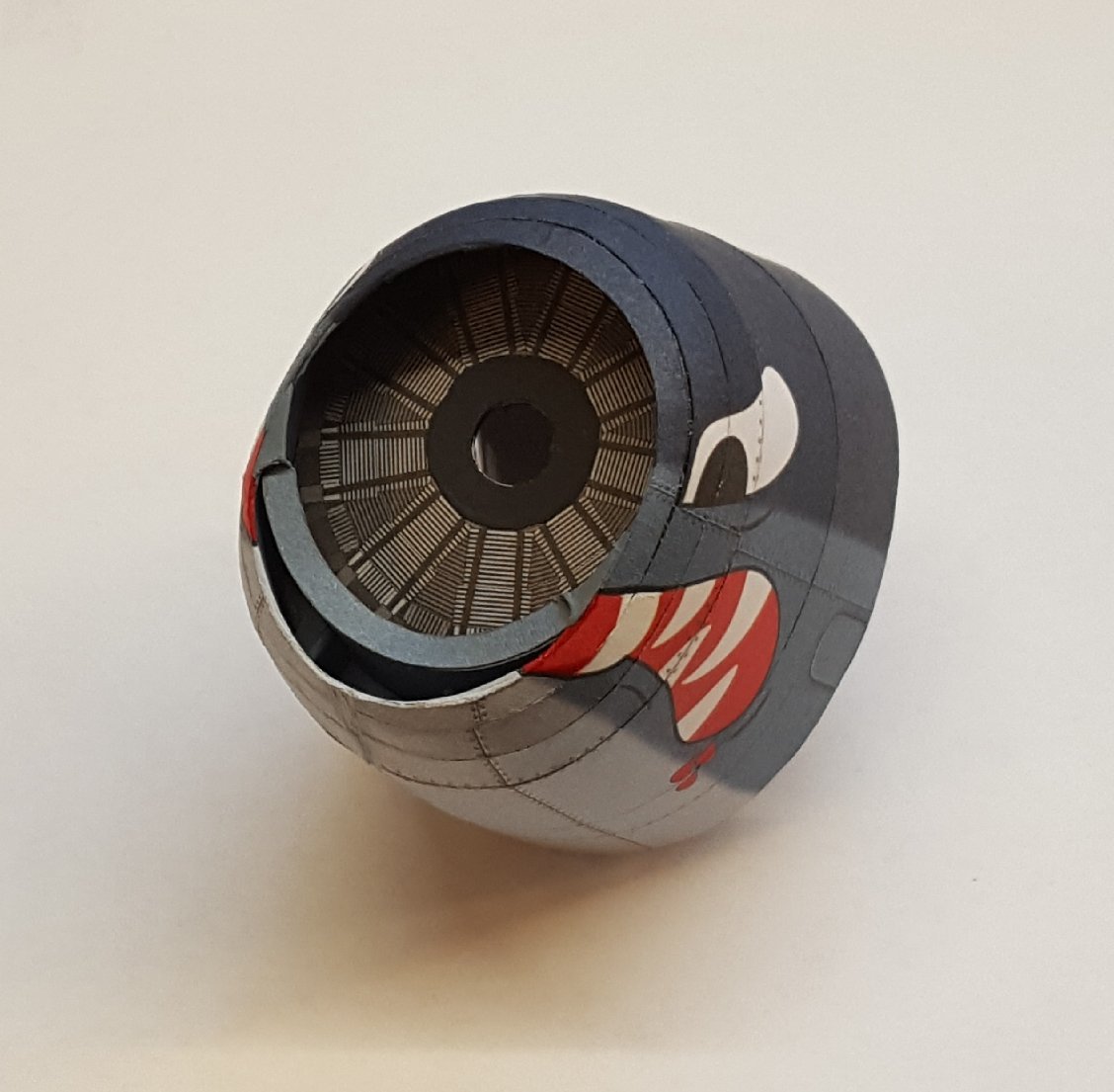
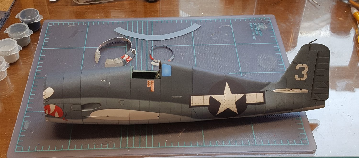
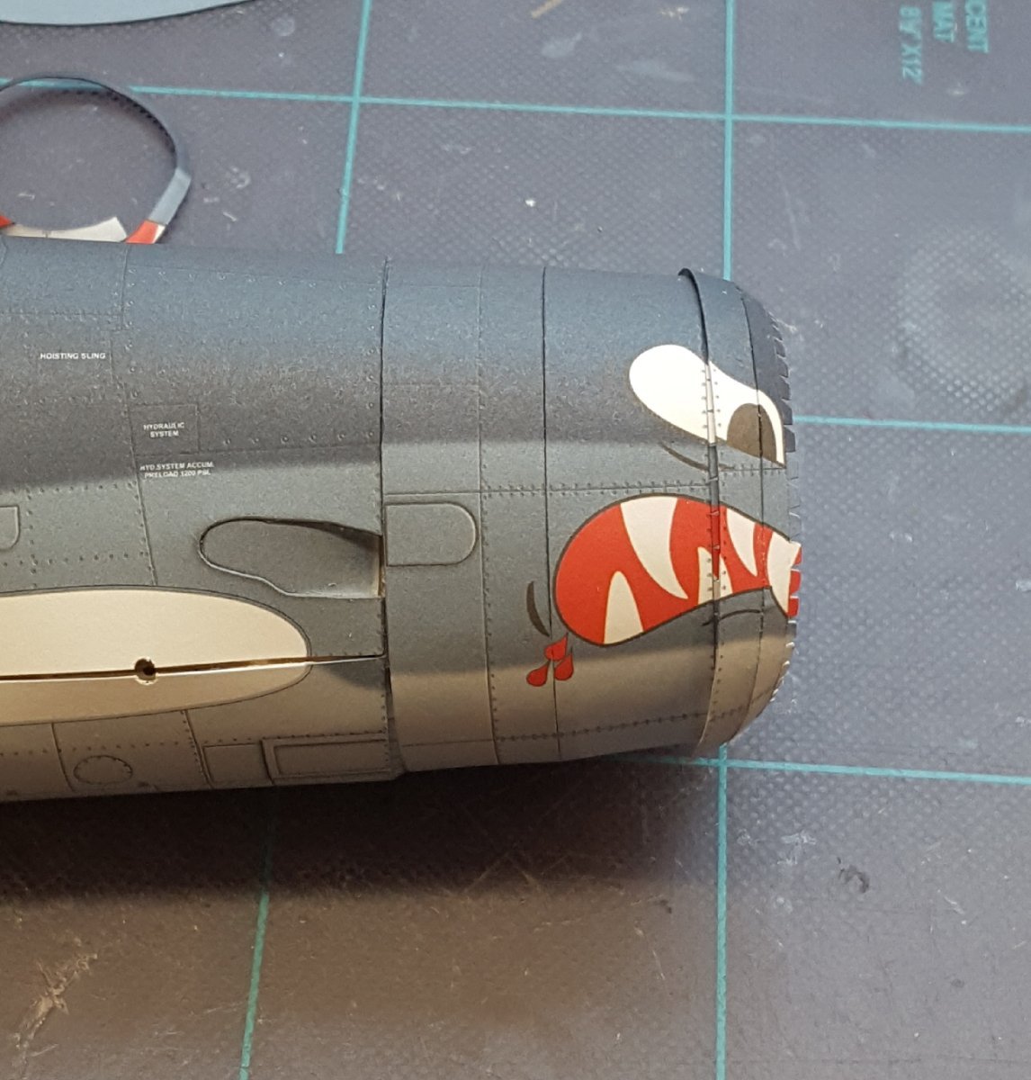
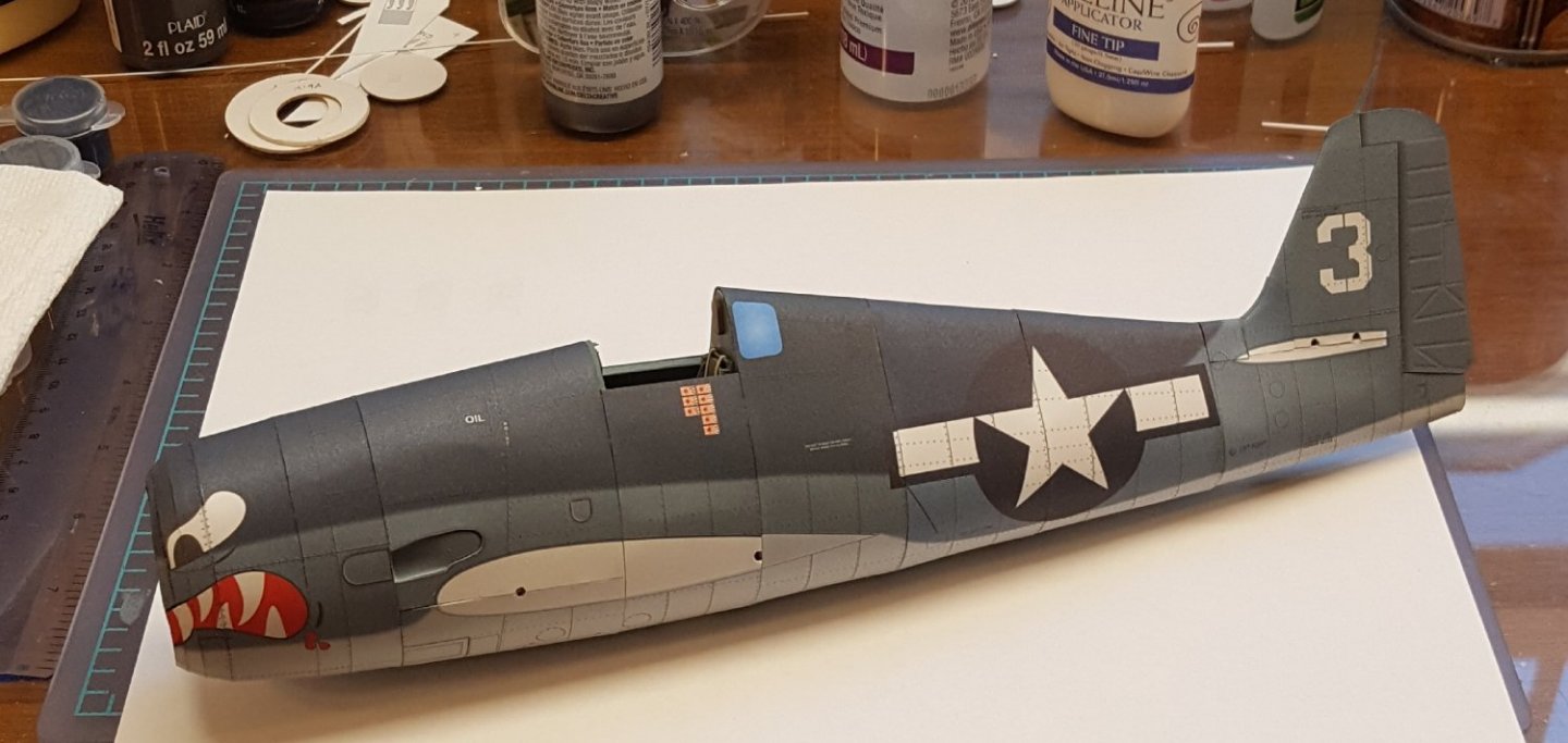
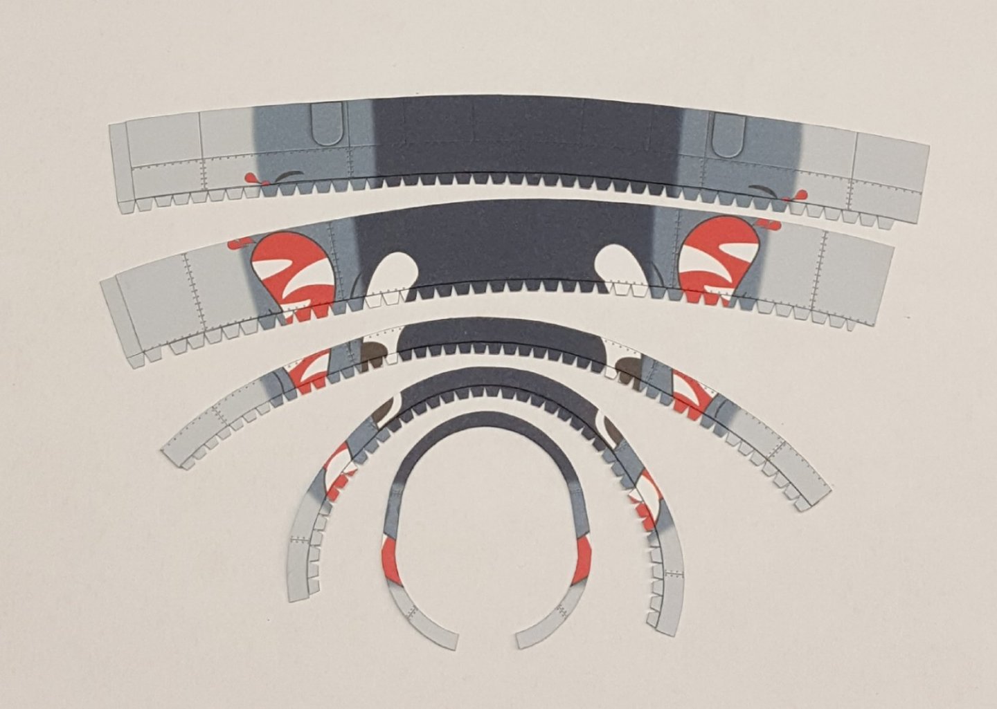
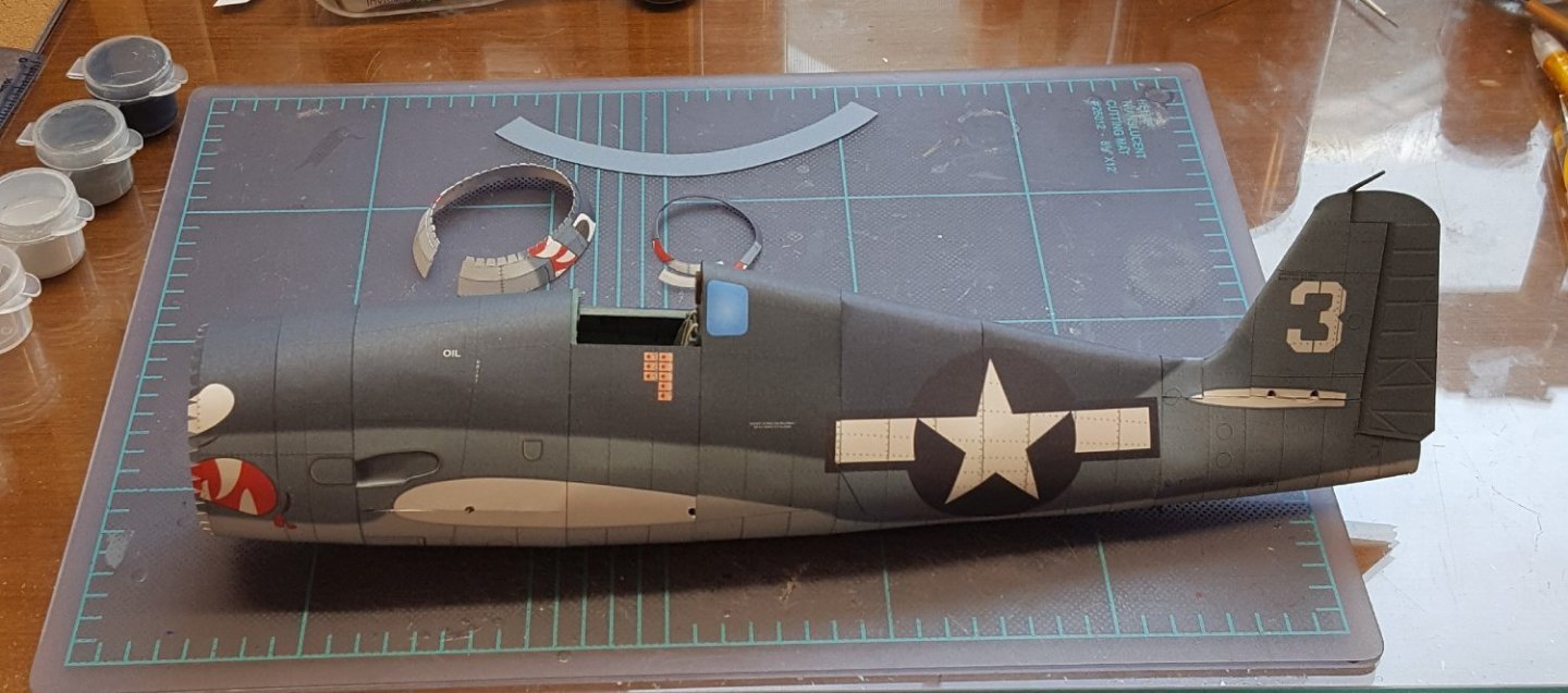
Well, another update. I got the forward fuselage and cowl finished, but it WAS NOT FUN. It took me quite a while to figure out how the various parts were supposed to go together, based on the somewhat nebulous diagrams. Then it took me another long while to screw up the nerve to actually start gluing stuff, and the stuff didn't just fall together but instead required substantial fiddling and shaping just to get at something acceptable. Then it took me yet another long while to do all the touch up work after the gluing was done. Blech!! First, a shot of various structures strewn about on my cutting mat. I had to do surgery on the forward-most frame to make room for the air scoop to fit in. The scoop itself is a complex shape made from eight parts. The front three cowl rings did not line up properly, which required some follow-up surgery later. You'll note that I opted to use the flat, printed engine cylinder piece rather than make the individual cylinders. Based on how difficult it was to make everything come together, this was probably a smart decision. So, here's the finished nose section. I had to do some additional nips, tucks, fills , and touch-ups to get this to look half-way decent. And here it is after gluing it to the fuselage. I noticed just now that the front of the cowl got a little deformed during the mating of the fuselage sections, so now I'll be off to fix that. Cheers!


- 150 replies
-
- 19
-
-
My First Kit Pick Ups.... Beginners Kit Recommendation?
ccoyle replied to DeHammer's topic in Wood ship model kits
Well, I thought I remembered seeing a build log recently, but perhaps I was mistaken. I might have been confusing it with one of the other BB kits. -
My First Kit Pick Ups.... Beginners Kit Recommendation?
ccoyle replied to DeHammer's topic in Wood ship model kits
I know at least one member of this forum who really likes Billing Boats kits, and he does a great job building them -- the builder is the key. And if you do a search for "Billing Boats Dana," you'll see that we have several completed examples in the gallery. It can be built into a very nice model. The main thing is to have fun and feel a connection to whatever you happen to be building. Now, very soon some other members will chime in with suggestions for beginner-friendly kits, and you may certainly take those under advisement. But, once you make your decision about how to proceed, commit yourself to simply enjoying the journey. Cheers! -
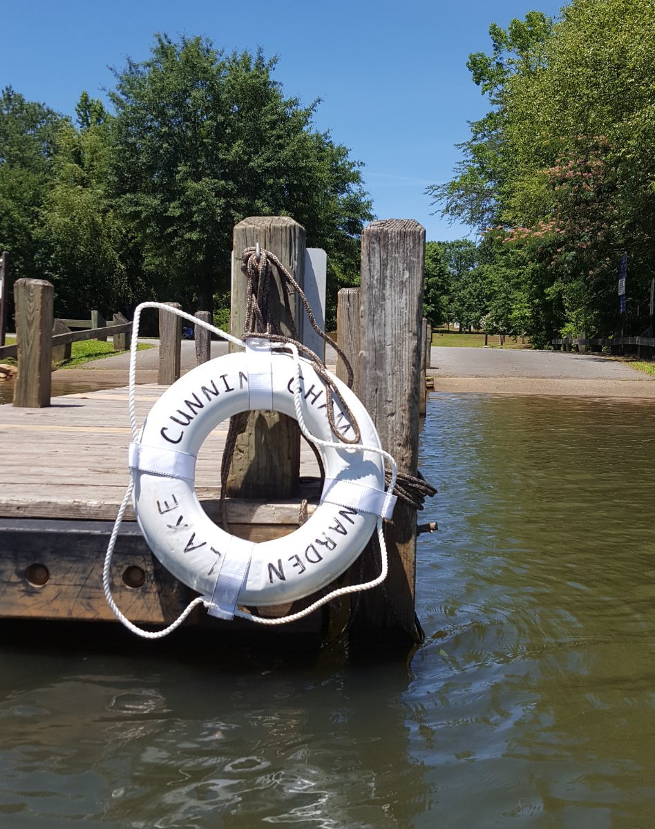
Wow! What a beautiful place to call home! Hope you enjoy your time here. Cheers!
-
Most models are actually 'mixed media' to some degree. Your bollards will like fine to the average viewer. I once knew a great modeler who described his models as 'artistic impressions' -- they looked a little rough if you looked too closely, but at normal viewing distances they were lovely.
-
Well, that is a major bummer.
-
What's a good kit for learning rigging?
ccoyle replied to Mark m's topic in Masting, rigging and sails
I agree with Allan. Those kits are on the 'stylized' end of the kit accuracy spectrum -- the rigging in particular is highly simplified. Also, as a beginner, you will find it much easier to take on the myriad number of small elements on a ship model if you steer toward larger scales, e.g. in the 1/48 to 1/64 scale range. -
I'm acquainted with Super-Hobby but have never ordered from them. They carry card models and usually have a good number of photos of the actual kits, something that most retailers don't usually do. I hope you have a positive experience with them.
-
Outstanding workmanship, especially at this scale. I like the muffin tin liners for sorting parts -- I might have to borrow that idea.
- 13 replies
-
- 5
-
-

-
- Dom Bumagi
- Admiral Nakhimov
- (and 1 more)
-
Get well soon, Bob!
-
For a few seconds I thought your kit had a seriously warped keel, but then I realized that was the deck and that the keel was laying flat, so no problems!
-
What's a good kit for learning rigging?
ccoyle replied to Mark m's topic in Masting, rigging and sails
Cutters are good projects for tackling the more advanced masting and rigging found on square-rigged vessels. They typically have only a single mast. so they are not overwhelming for beginners. There are lots of cutter kits to choose from, too. The armed Virginia sloop suggested earlier is not technically a cutter, but it has a similar rig, so it is a good choice as well. Your lobster smack project will have a simple fore-and-aft rig -- if you want to take that type of rig up a notch before taking on a square rig, then try a two- or three-masted schooner. Again, lots of such subjects in kit form to choose from. -
Started work on the forward fuselage. Here are the skin sections with their joiner strips attached. Each of these must first be pre-formed as close as possible to the desired finished shape. The largest piece (top) was then closed, gently conformed to the shape of the previous fuselage section, and then allowed to remain dry-fitted for 24 hours to permanently 'fix' its shape. Then the next section was closed, shaped, and glued to the first section. After the glue had set, an internal bulkhead was placed inside the resulting cylinder and glued in place. Here's the work so far -- the two fuselage sections are not yet glued together. In the previous photo,you can see the next two rings joined together in the background. The two forward-fuselage assemblies won't be joined together just yet -- both the engine and air intake need to be built first. But, I couldn't resist getting a feel for what the finished nose will eventually look like. Yep, it's going to look cool! In the photo, you can also see where I have added the optional recessed exhaust port. On photos of real Hellcats, there is usually a massive, dirty streak that arcs back from the exhaust port along the fuselage and over the wing root, as you can see in the photo below (from Wikimedia Commons): The kit printing doesn't have any weathering, but I am half-tempted to try adding this rather conspicuous detail. Cheers!

- 150 replies
-
- 19
-
-
Interesting subject, Dan. I did not know about the incident. A challenging project, to be sure.
-
Yup. I have done both with and without. Don't hesitate to add them if that's the look you like. The one recommendation I would make is to steer clear of pre-sewn sails as these rarely, if ever, look 'right'.
-
Good to see that I'm not the only modeler who must zealously guard his stash of tools and supplies from unauthorized uses.
-
Man, your 'model' is as big as my canoe I finished last year!
- 454 replies
-
- 3
-
-

-
- Union Steamship Company
- Stepcraft 840
- (and 3 more)
-
Attn: ALL LINDBERG Model fans! (Test your knowledge?)
ccoyle replied to BoSmith_12's topic in Plastic model kits
Try searching Scalemates. They have quite a few Lindberg kits listed.