


KeithAug
-
Posts
3,867 -
Joined
-
Last visited
Content Type
Profiles
Forums
Gallery
Events
Posts posted by KeithAug
-
-
1 hour ago, wefalck said:
Apart from the fact that it may have been knocking about in your workshop,
Eberhard - As you say one reason was that it was available. I had (have) many options.
1. Over plank with 1/32 mahogany strips.
2. Clad in metal - brass / copper or similar .020 thick
4. Build it up using filler (against edge strip guides).
5. Make it out of .020" card.
6. Use .020" aluminium foil sticky tape.
7. Use 1/32 birch ply.
Im sure more options are available and guess I will have a lot more options within a few hours of posting this.
My guess is that the plate protrusion is circa 0.5" and with a bit of sanding both the "wood" options would come back to about this thickness.
The mahogany planks option just seem a bit tedious (i have had enough of planking for a while).
I don't want to adopt the metal option because it's expensive for a model of this size and it would involve a lot of pieces that would have to be seamlessly matched together. The maximum size of .020" sheet readily available is 300mm. Also the complex bending to match the hull is probably beyond my patience.
I thought it would be quite difficult to get a consistent thickness of filler.
I'm never sure about card. My worry is it won't look anything like steel once painted.
I was surprised to find .020" (0.5mm) tape. It isn't cheap but this might be my fallback option.
I think birch ply is the best and cheapest option (particularly if I ignore the bending problem). I am not too worried about getting it to bend. Famous last words 😬. I will find out within a few days.
- mtaylor, Keith Black, wefalck and 7 others
-
 10
10
-
Thank you Gary - and thanks to all my other viewers, your visits to my log are much appreciated.
Well that's another week gone by. We have had the builders in this week so I needed to watch what they were up to. We all get spoilt by MSW contributors attention to detail. I don't think any of us would be able to achieve general builders standards!
As usual Cangarda progress hasn't been stellar.
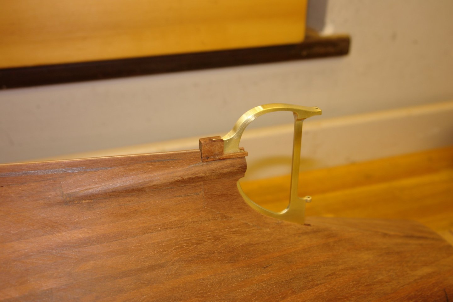
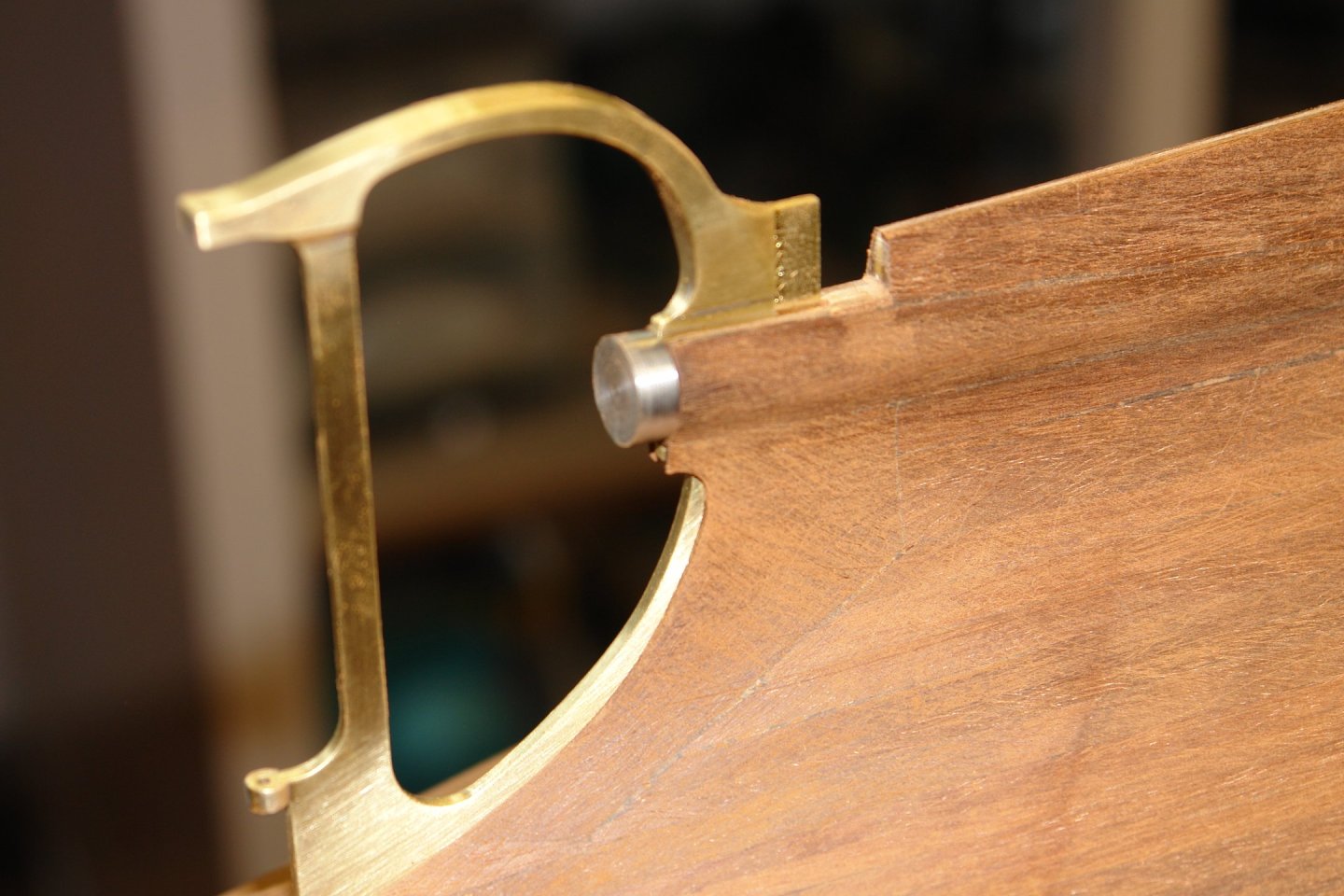
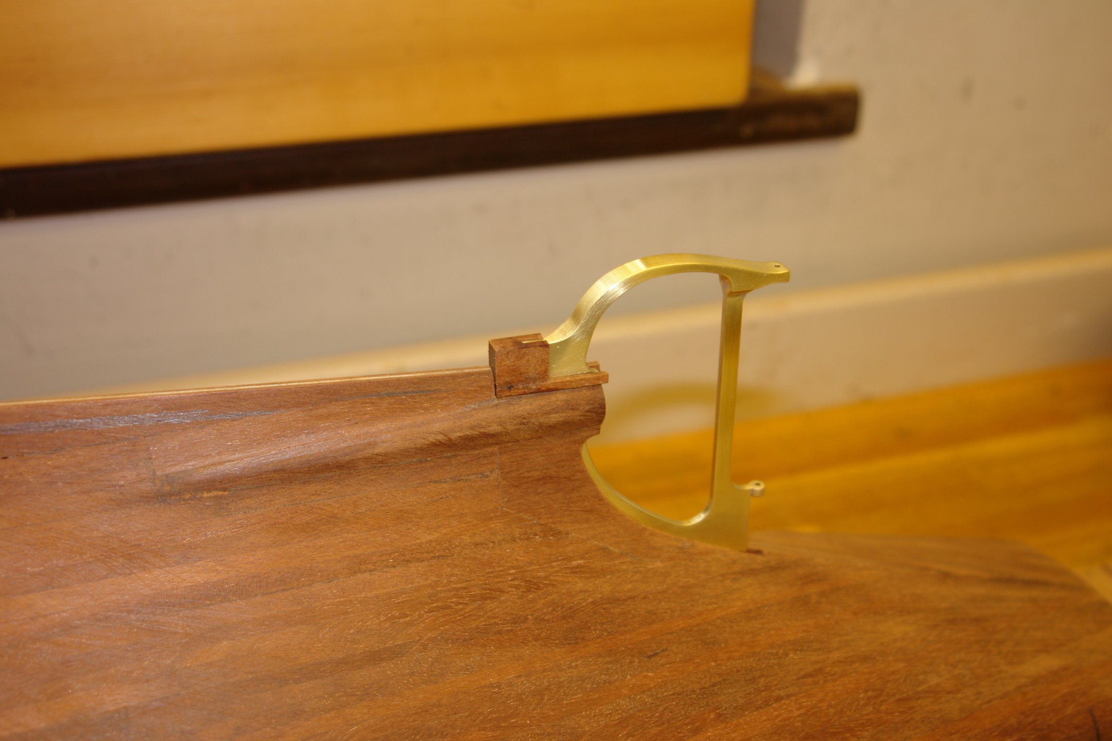
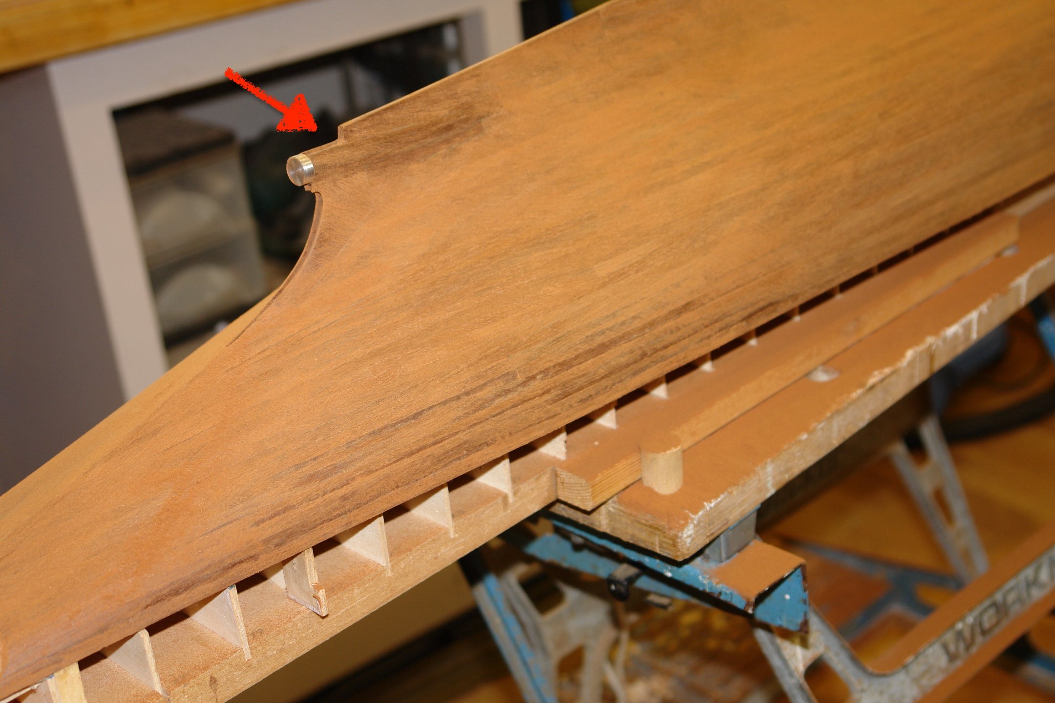
Firstly I drew the plan for that little bit at the end of the keel that I damaged.
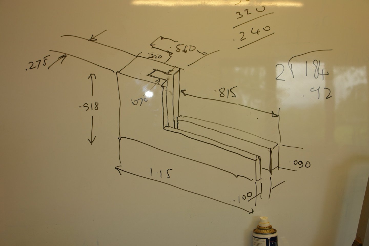
I then made it. I didn't shape it or glue it on though. I am saving that for a bit later when damage is less likely. Once bitten twice shy!
The next step in the build was sorting out the stress compensation plate that runs the full length of the hull.
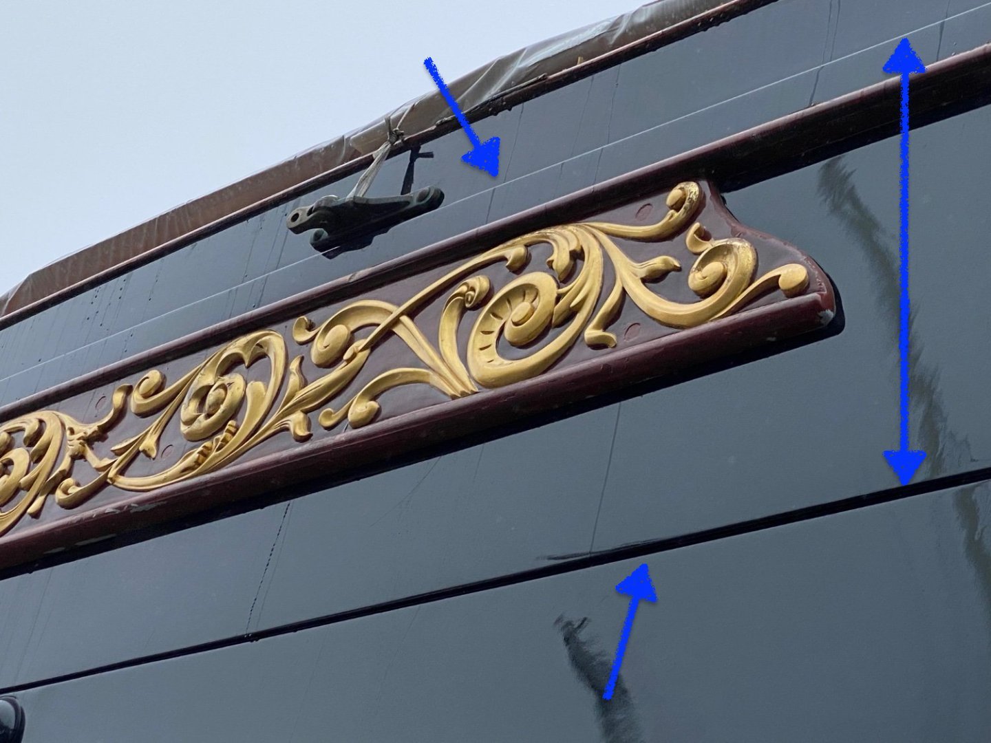
I am going to create this by overlaying the hull with 1/32" birch ply. (Hence my previous comment about needing to paint the hull above the waterline).
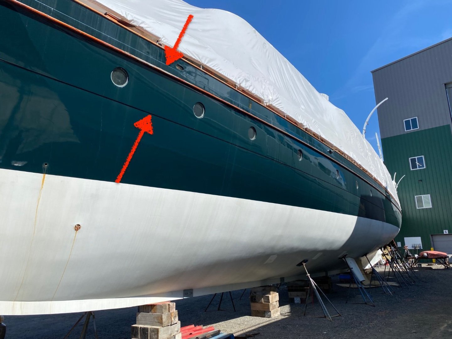
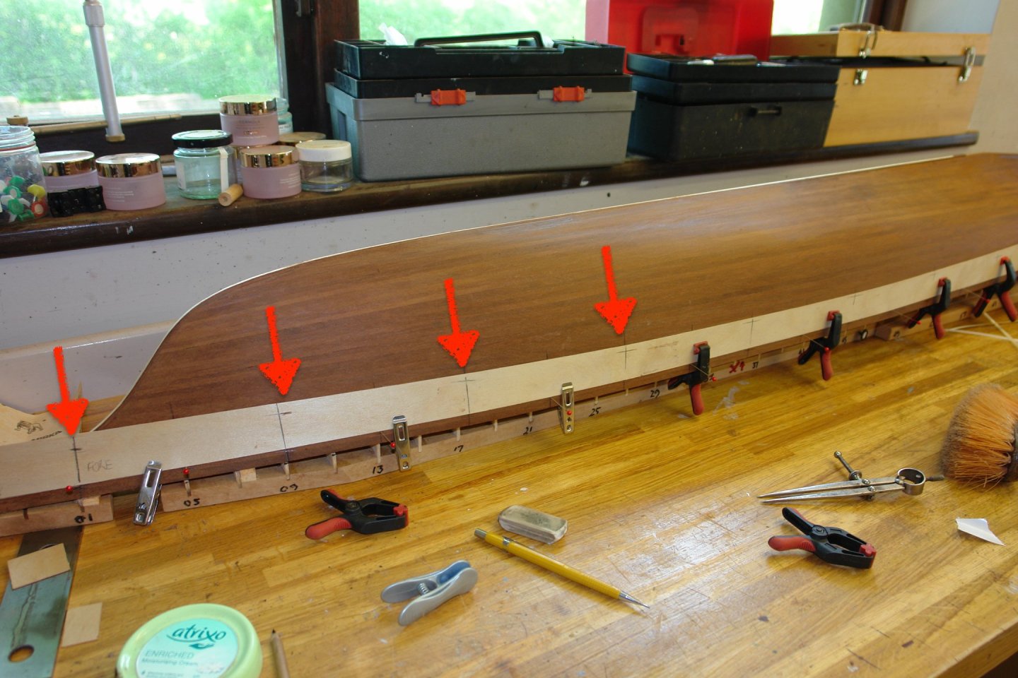
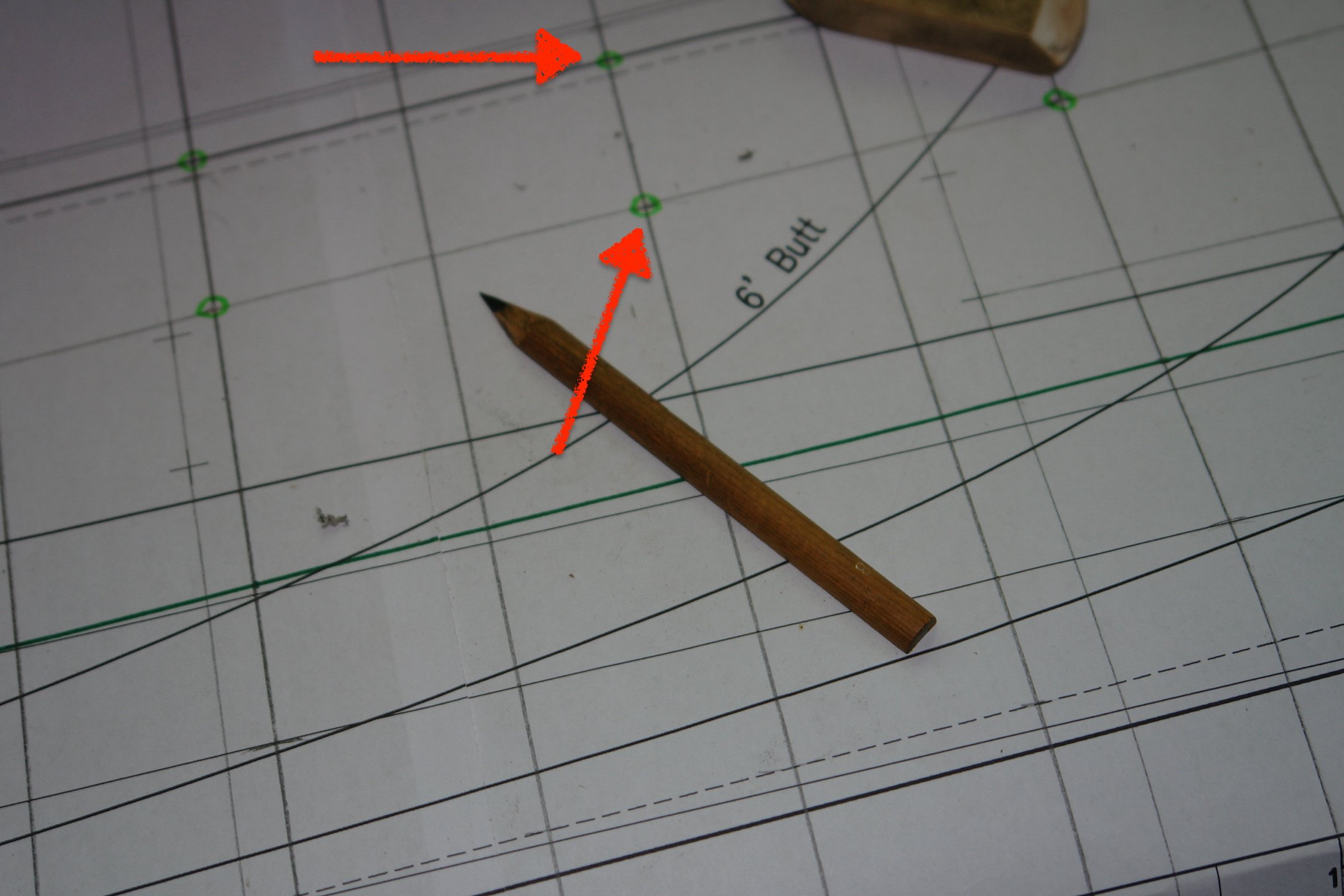
Getting the compensation plate correctly shaped and positioned could have been tricky had it not been featured in one of the drawings supplied by Rutherford's Boat Shop.
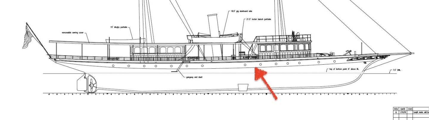
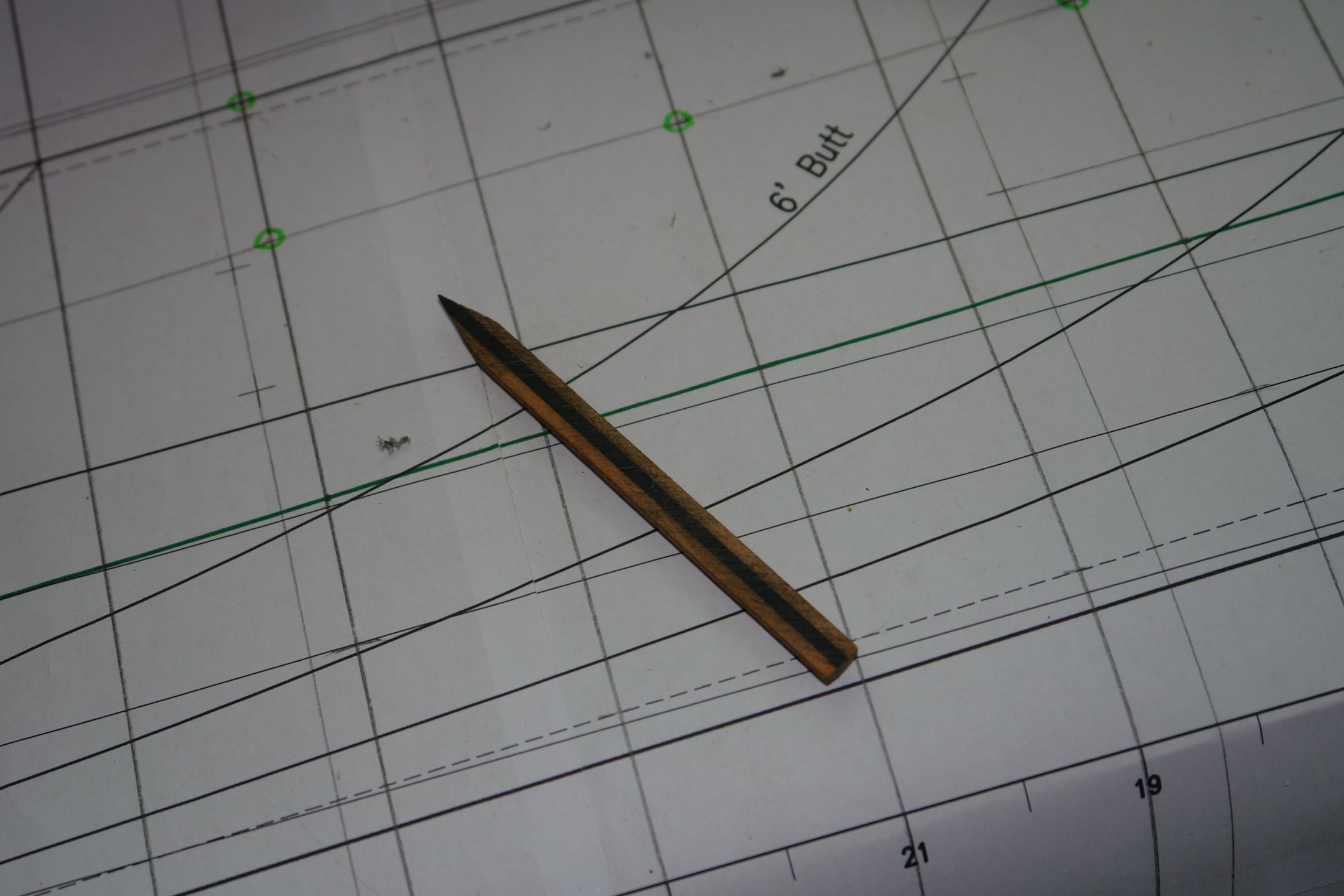
I transferred the position of the compensation plate on to the lines drawing (red arrows) . Also note my special pencil.

I needed the pencil to draw straight lines on the hull as the hull curved away from the straight edge. Hence I cut the side off to eliminate the effect of the cone produced by the pencil sharpener.
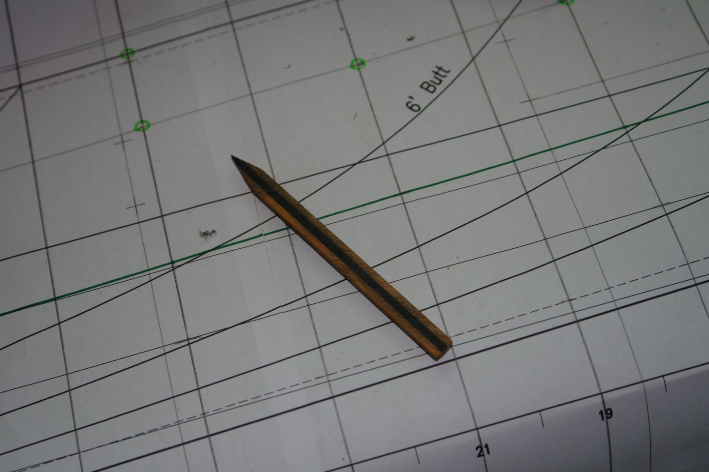
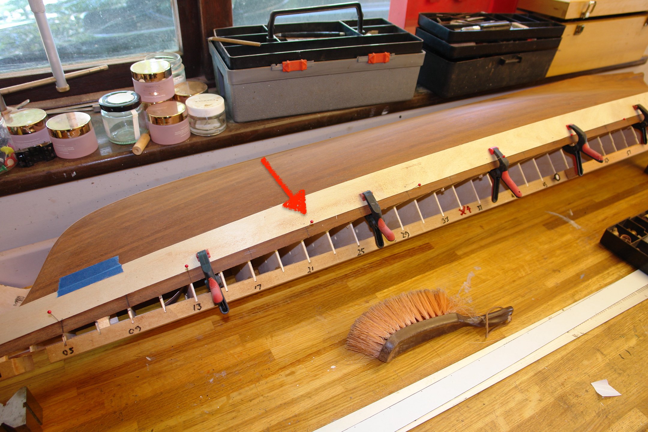
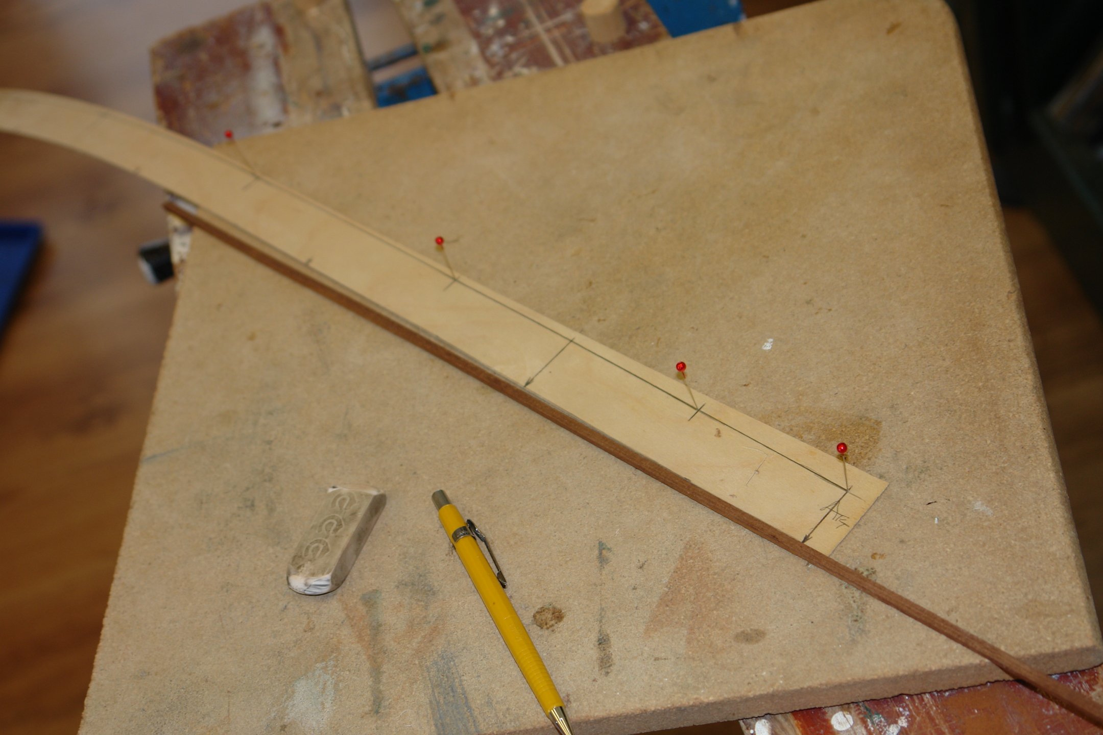
The frame lines were then transferred to the hull at the positions corresponding to the green dots in the previous photo. The vertical height of the top edge (or is that the bottom) of the compensation pate was then marked on (just noticeable on the next photo).
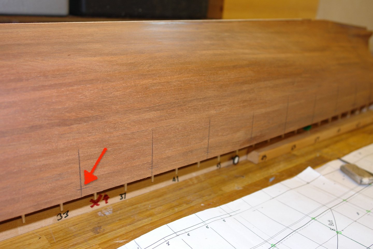
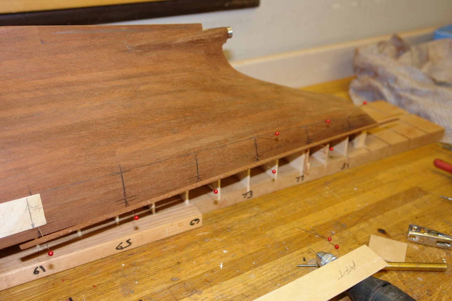
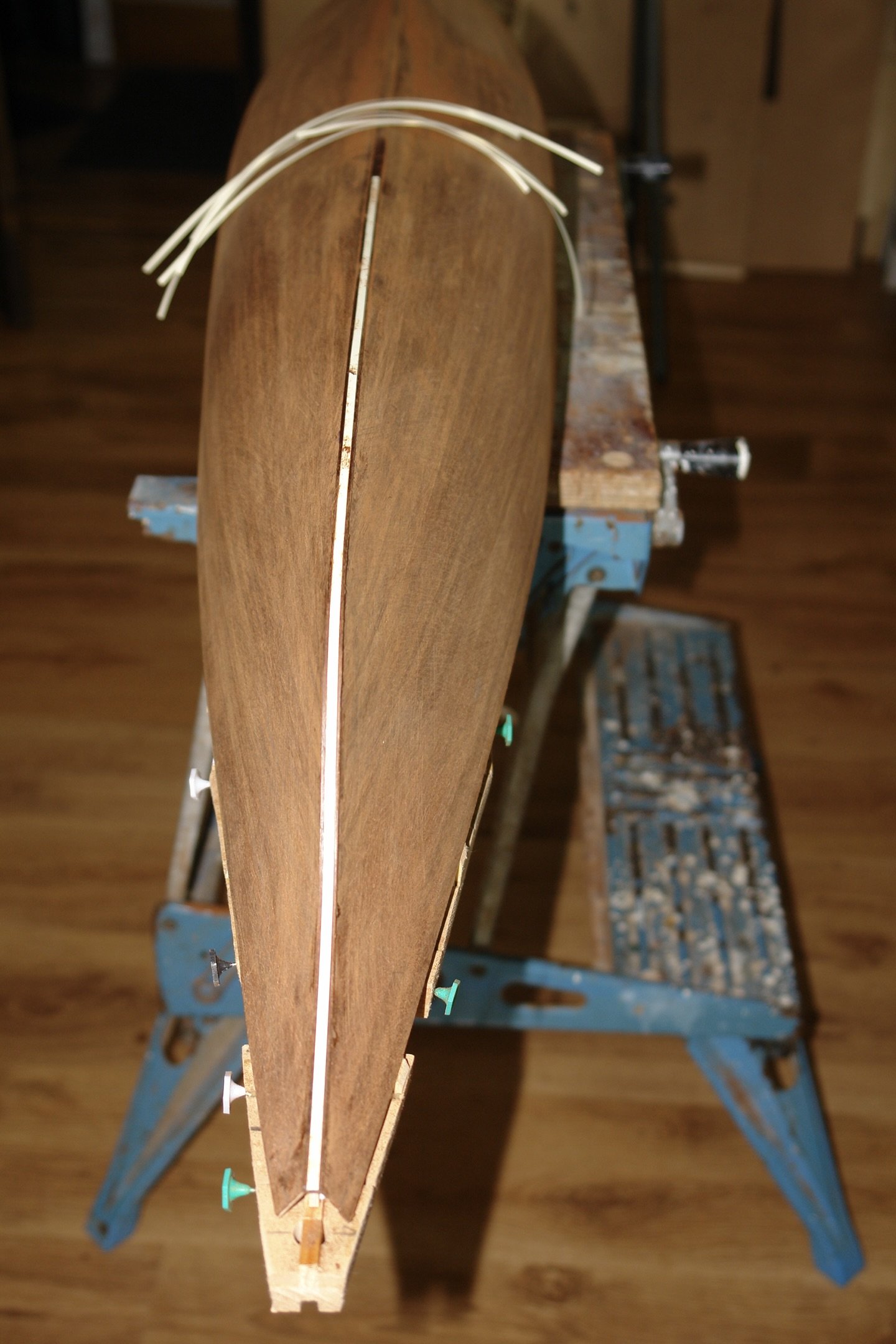
These points were then drilled with a .025" drill and sewing pins were inserted to define the line against which the plywood compensation plate needed to butt. An over width birch strip was then cut and offered up to the pins.


Despite what the photo looks like the strip didn't butt up to all pins. The amount needing removal was then marked on the strip a this was planed away slowly while frequently checking the fit. The shaping is fairly obvious in the next photo.

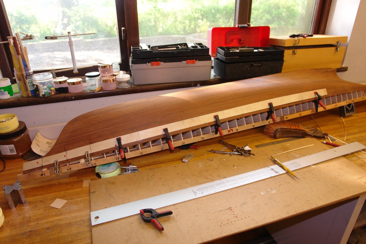
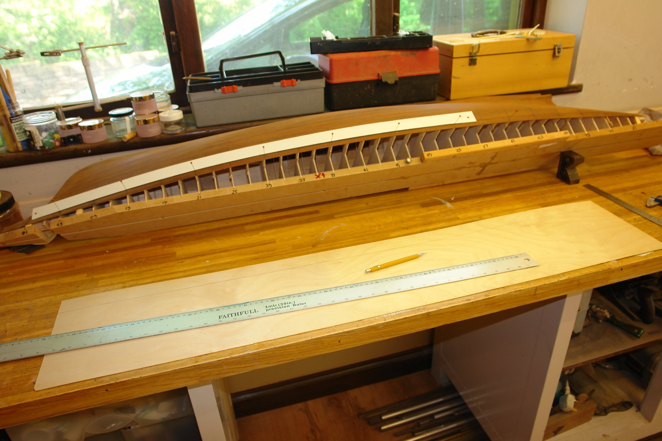
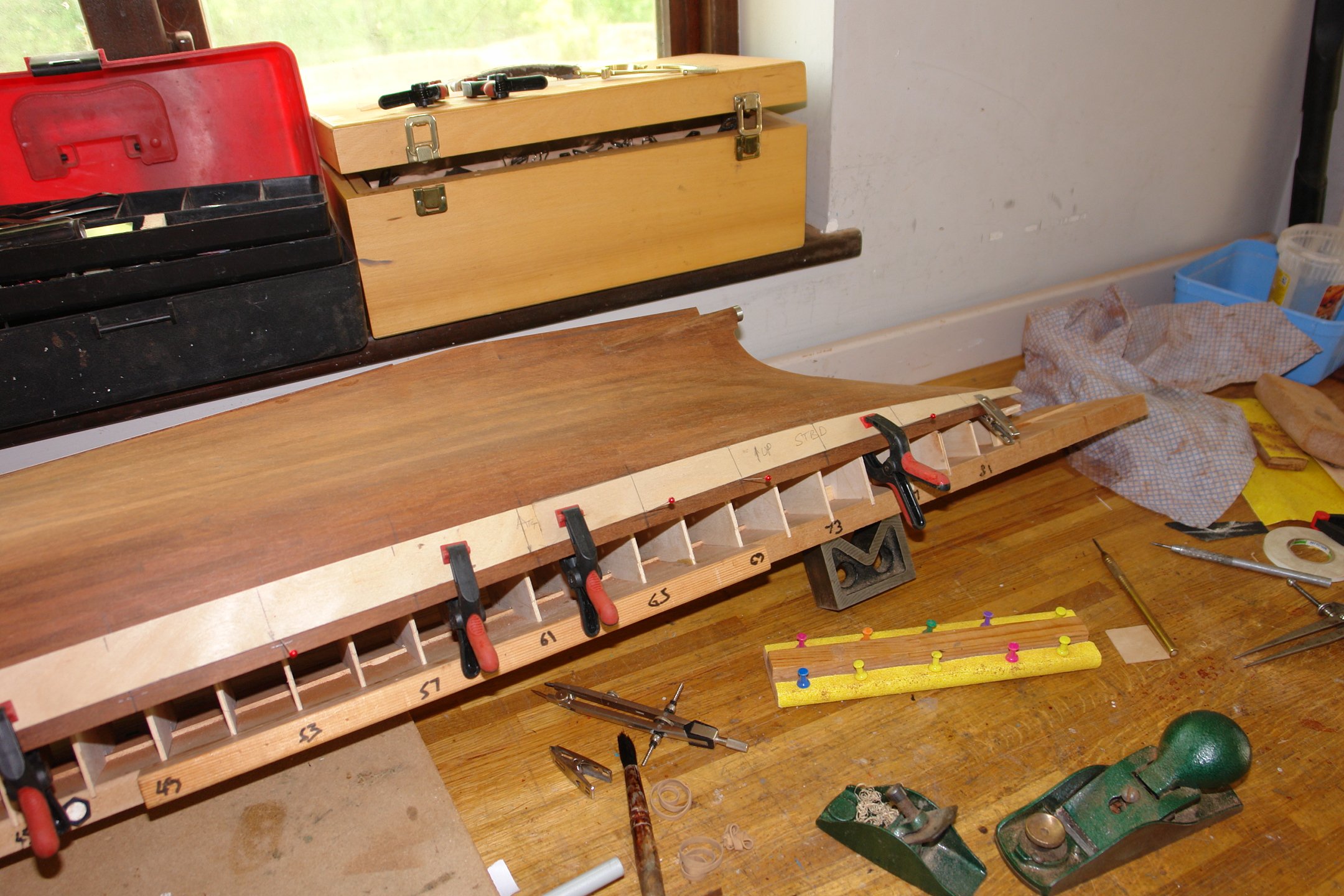
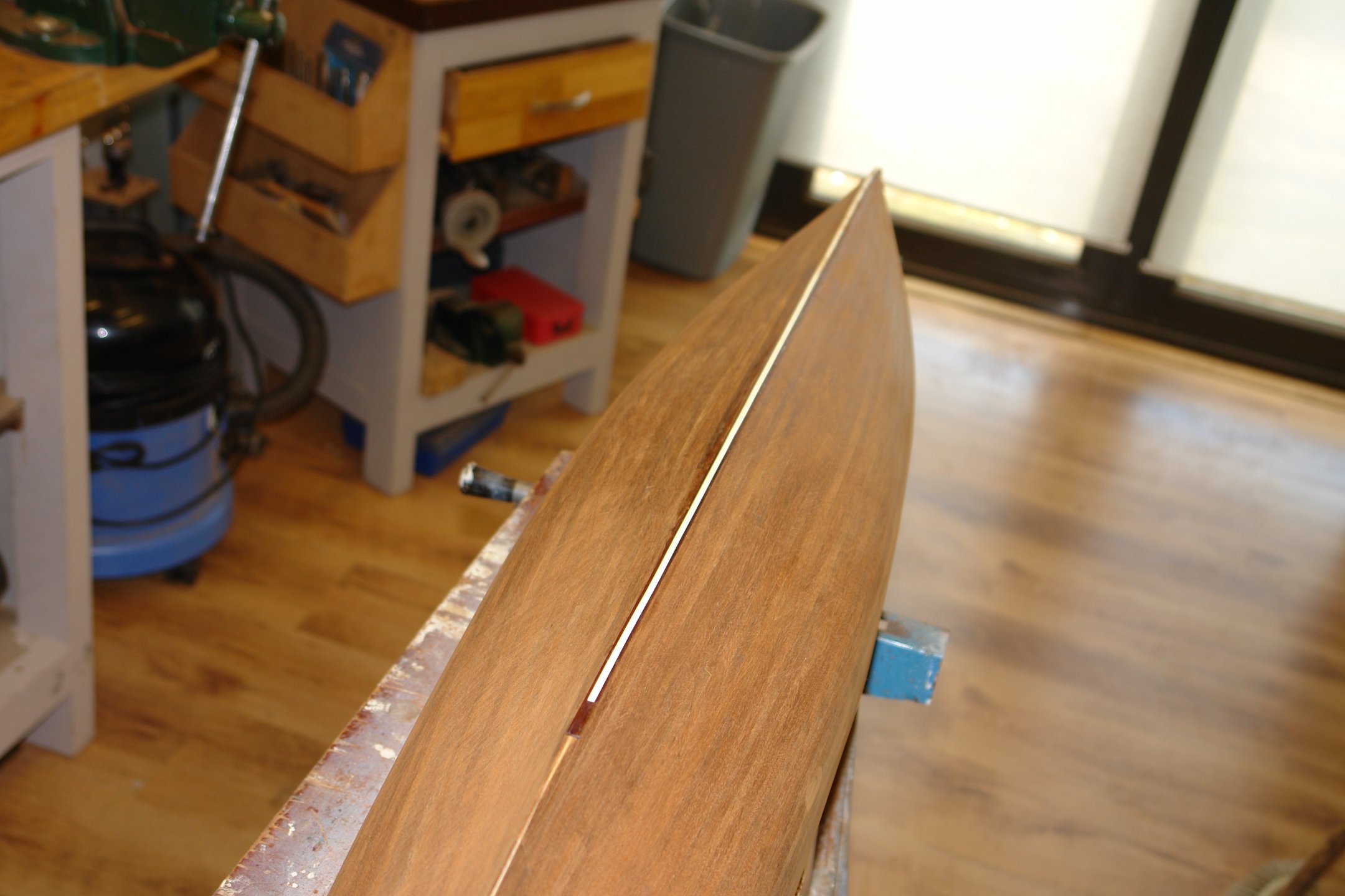
Once the correct shape was achieved it was clamped against the hull in preparation for transferring the lower edge positions on to the strip. The next photo shows the positions being marked. You will see the plate doesn't run the full length of the hull because I only had a 4 foot sheet of 1/32 birch ply.
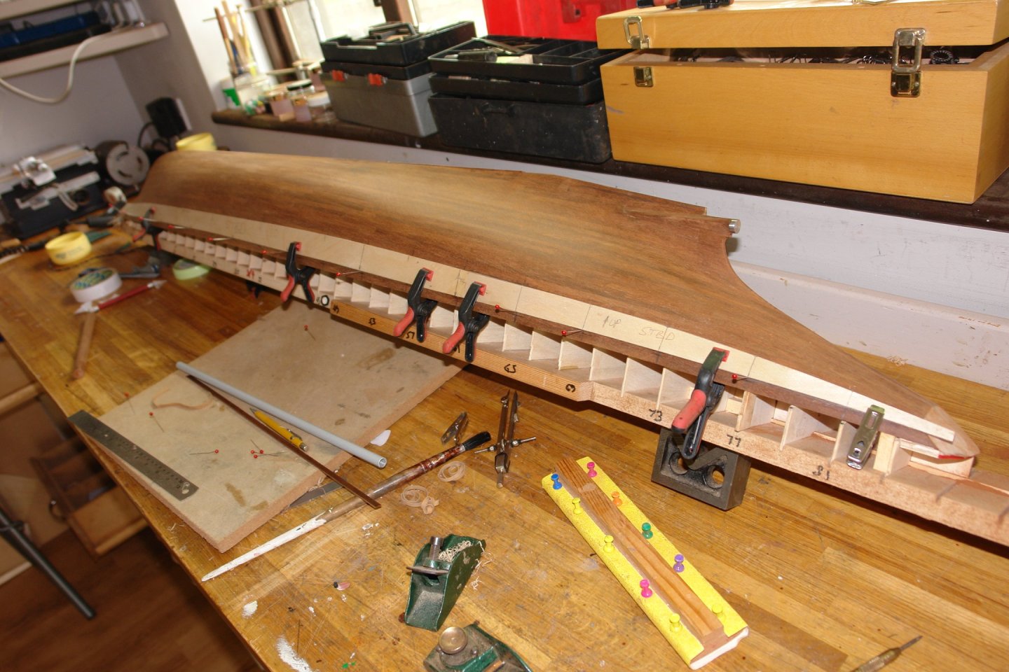
Because of the more pronounced vertical curvature of the hull at the stern the compensation plate plank wouldn't fit flush to the hull. I therefore needed a different approach to marking the shape of the plank. Hence both top and bottom edges were marked directly on the hull.
The bottom (or is it top) edge of the front plate was then marked. I like to draw the curve by putting pins through at the marked out points and then pressing a flexible stick up against the pins to define the curve. I find the cork mat very useful. Many years ago it was a feature off the bathroom floor.

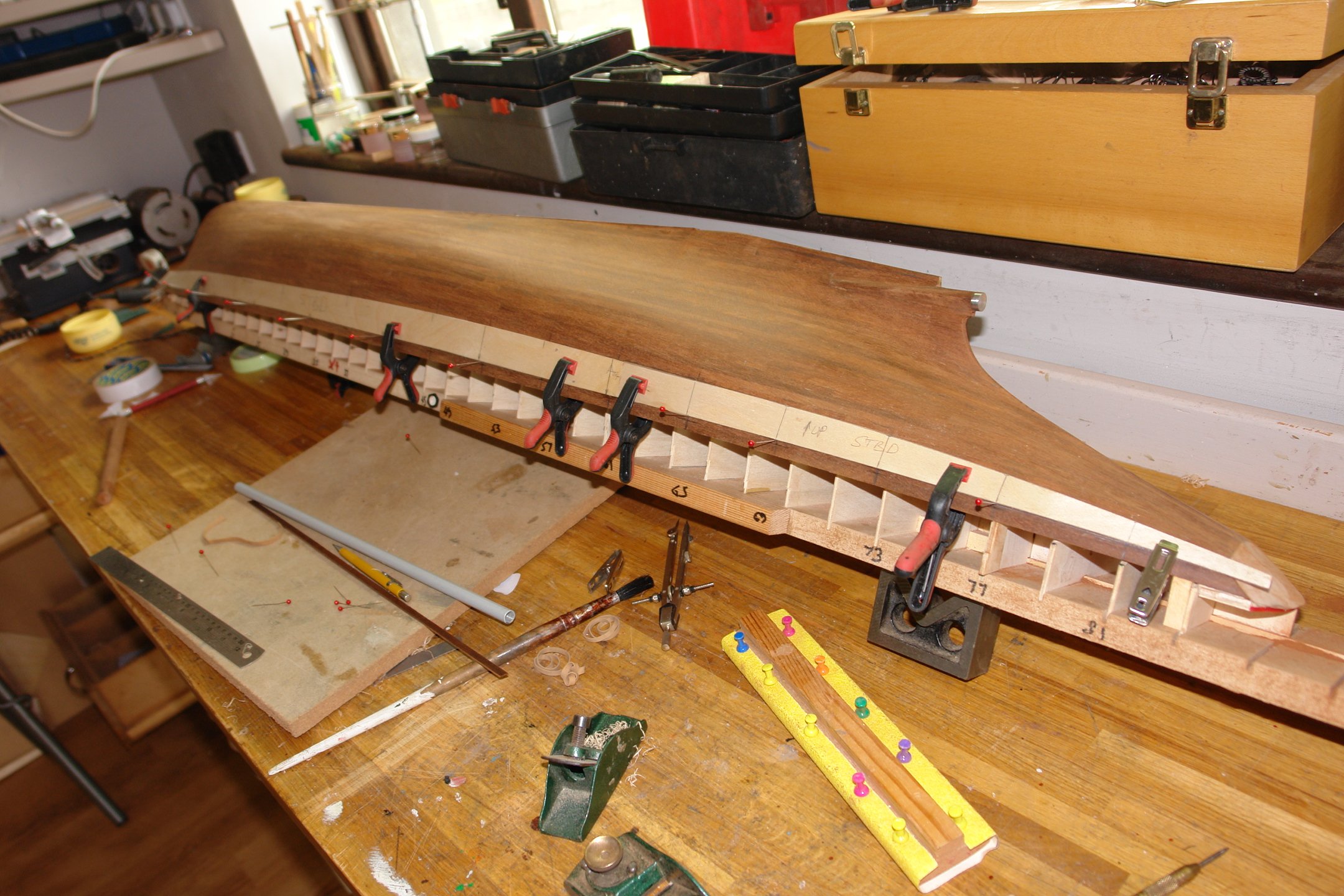
The following shot shows the shaped plank held in position by clamps.
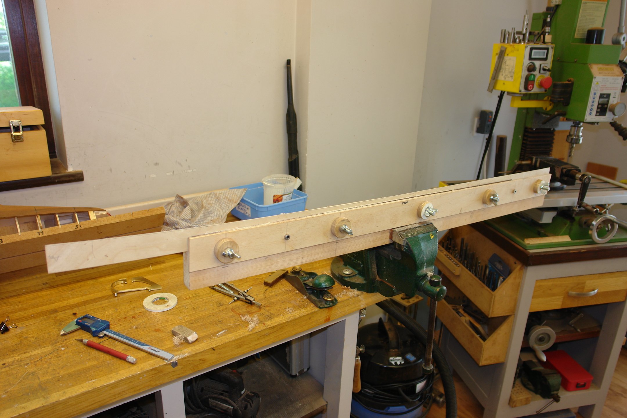
The stern compensation plate was manufactured in the same way as the bow one and offered up to the hull. I took some time taking off fine slivers to get the upper and lower edges flowing together nicely at the join.

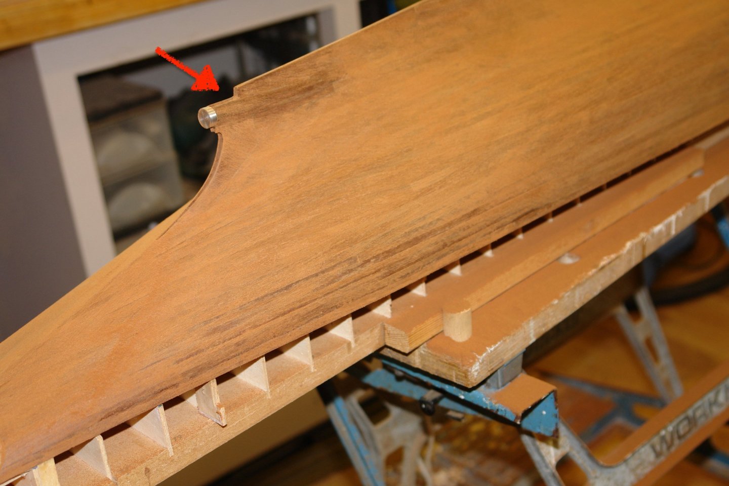
The port side plates were then made using the starboard side as patterns.
The vertical curvature of plate at the stern is going to be a challenge, it just don't wanna flex that much!!!!!!!!
That's all friends.
-
18 hours ago, Javelin said:
I believe @KeithAug is talking about stability rather than keeping the ship level.
That is correct Roel. I was thinking about those very long beams and steam plant sticking up above the deck in combination with that very narrow beam.
It obviously works but the plans posted on Keith B's answer don't provide a lot of comfort. Not a vessel to take out in a blow!🙂
1 hour ago, Keith Black said:My poor ole Tennessee is sitting there with that 'what about me' look on her bow.
She will be ok - she has Ole Bob for company.
- tmj, Glen McGuire, mbp521 and 3 others
-
6
-
-
-
10 hours ago, Ras Ambrioso said:
Regarding the ladders, Ken Kenny's system uses a long piece for the sides of the ladder and then sets the miter gage to the stair angle.
Ras - yes I had previously viewed that video. The main difference is that Mr Kenny's method has many more operational steps and hence more opportunities of errors to creep in. By attaching the side strips to a backing block at the correct angle and then setting the saw to half the depth of the side pieces both sides and be cut (identically) in one pass of the table saw. The only thing that then needs to be set for each cut is the moving the fence by the distance between the steps.
Nice clean bends on the pipework. Well done.
-
2 hours ago, Keith Black said:
Keith? That hull is drop dead gorgeous, are you absolutely sure it's gotta be painted? I know it the Cangarda's hull is painted but geez.
Keith - the plan is white stripe at the waterline. Green above waterline. Clear varnish below the waterline. I think that is the best compromise. The green above the waterline can't really be avoided for reasons that will become obvious over the next couple of weeks.
Rick / Craig - thank you for your comments.
- FriedClams, Bedford, Keith Black and 4 others
-
6
-
 1
1
-
Paul. I am finding her surprisingly aesthetic given her quite angular lines. This probably owes a lot to the build quality you are achieving. All in all a very engaging build.
- Paul Le Wol, robert952, Keith Black and 2 others
-
4
-
1
-
On 7/17/2024 at 3:00 PM, FriedClams said:
I've popped in and out of your previous builds, but this will be first I've got in on from the beginning.
Ditto
-
Well you seem to be speeding through this build Keith. Do remember however that I am expecting you to take decades to finish it. No dashing for the finishing post for you old boy!🙂
- Keith Black, Canute, FriedClams and 3 others
-
2
-
 4
4
-
Well young Eric that turned out rather well. I think the deck cargo really adds to the realism and the weathering just lifts the whole boat to another level. I particularly liked the coal impregnated deck boards. I had assumed that the normal practice for river boats of this era would have been to fuel them with wood, but that clearly shows my lack of knowledge. I probably watched too much "Casey Jones" (Cannonball Express) as a child. Probably before your time🙂. Casey always seemed to burn wood.
Really looking forward to your next project - assuming you do a build log?????
-
Good progress Ras. Here is a variation on the method of making steps if you are interested.
- Canute, mtaylor and Ras Ambrioso
-
3
-
-
1 hour ago, scrubbyj427 said:
Just popped up on eBay this morning:
And popped out equally quickly!
- mtaylor, catopower and Ryland Craze
-
1
-
 2
2
-
Thank you Druxey, Gary, Keith, Andy, Steve.
So onward and upward. Now if you thought planking was mind blowingly boring, just draw up your seats for sanding time!
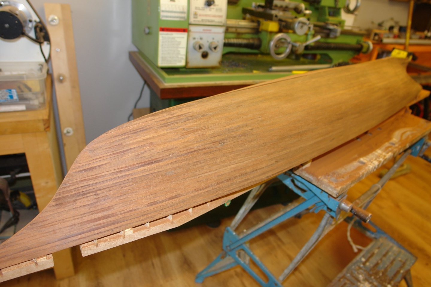
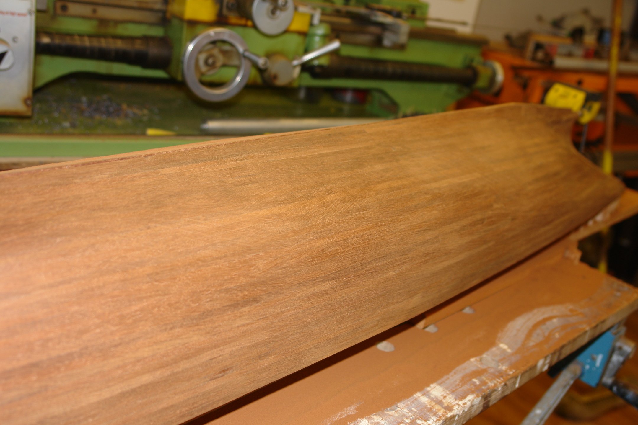
Firstly though, the excitement of the week was breaking off the fragile keel end piece (red arrow). No it didn't break off neatly, the neatness comes from a bit of fettling. You can see the plank edges beginning to disappesr with the application of 80 grit aluminium oxide paper and a lot of elbow grease. I use a cork sanding block 2"x3"x"1" and one 8"x2"x3/4". No electric sanding aids for this old luddite. Note the copious amounts of dust collecting on the B&D Workmate.
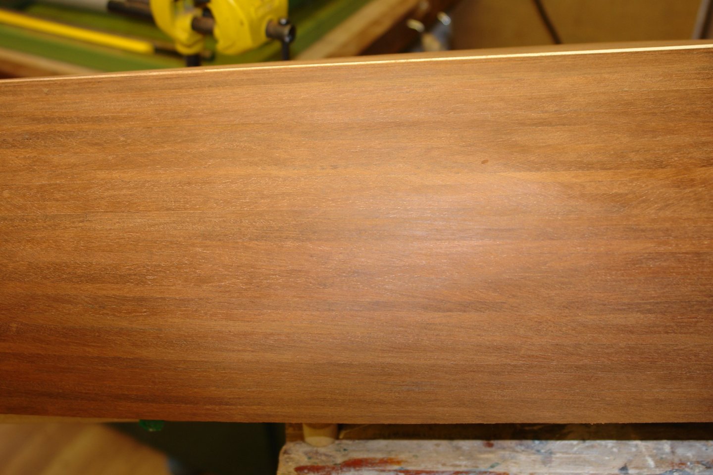
To feel that I am making some progress I work my way around the hull progressively.

The planking job seems to be handling the reveal quite well for the moment. The "sanding through the planks tension" builds just like electric car range anxiety. I comfort myself by starting to draw pictures in the sanding dust.
To break the excitement I pick up the broom and do a bit of dust mountain creation on the workshop floor. it was about here that I wandered into the kitchen for a cup of tea only to be thrown out because I apparently looked like the dust monster.

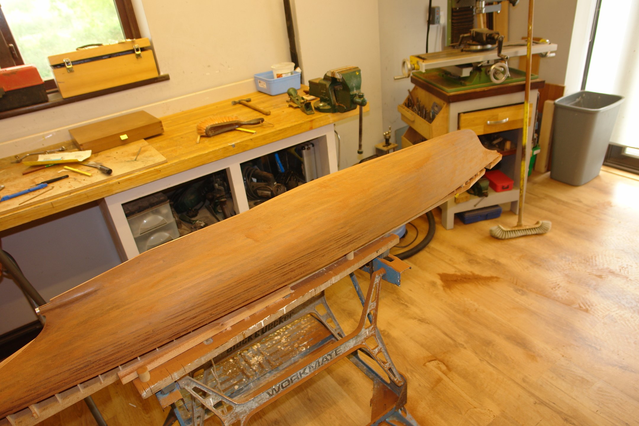
At this point "thickness anxiety" overcame me and I switched to 120 grit.
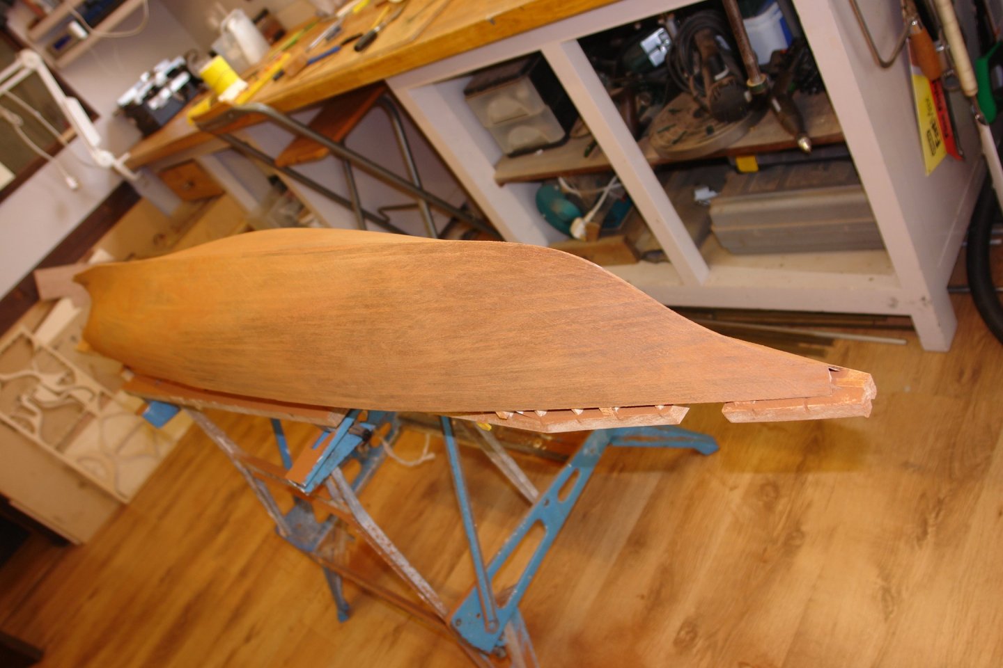
In my backward construction world it now seemed about the right time to retrofit the rabbet line. The pointy but at the front was sanded flat revealing the bow frame.
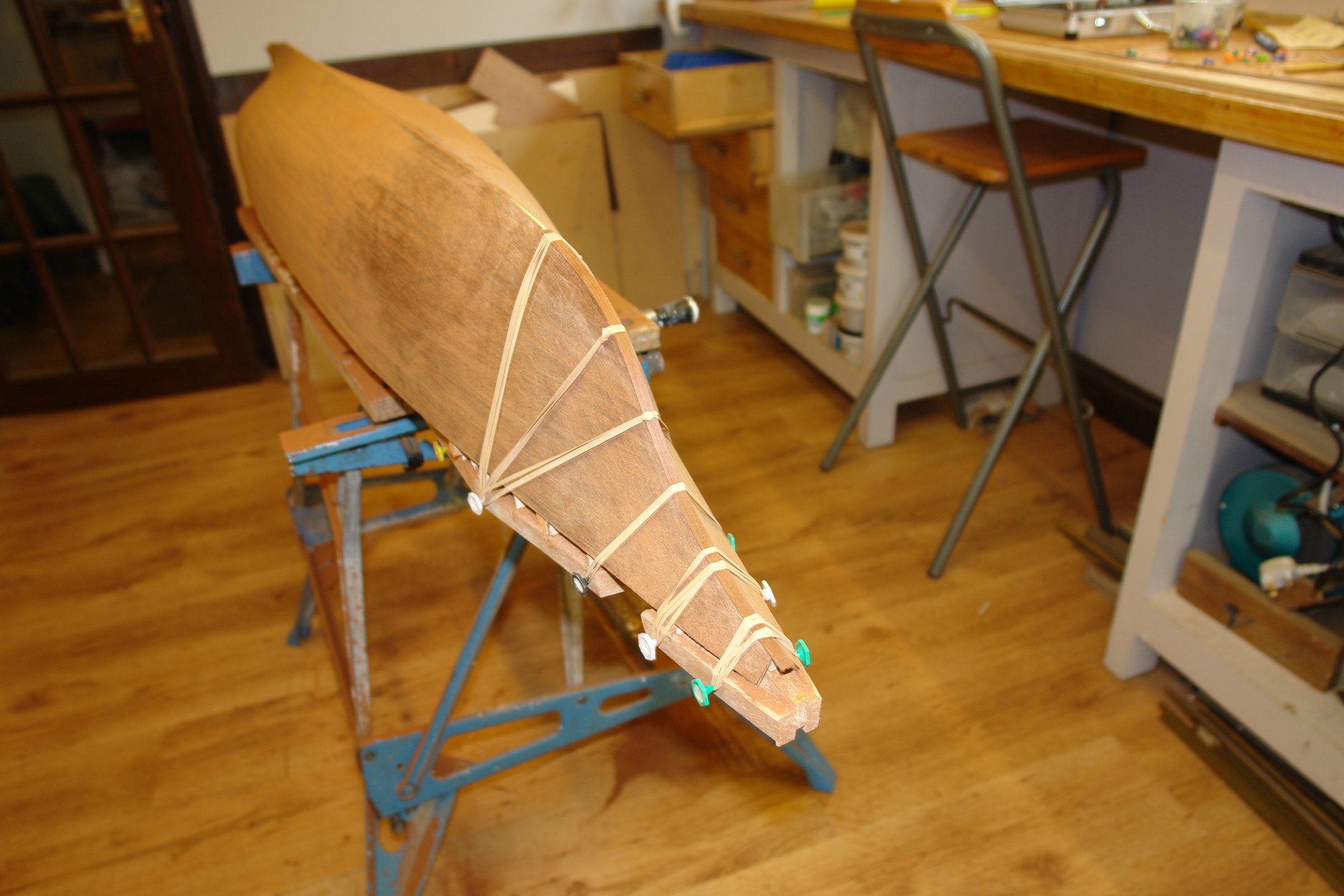
 This was then overlayed by a longitudinal plank over the bow and along the keel. Held in place by PVA glue, elastic bands and the "Mother of All Board Pin" (MOABp) missiles.

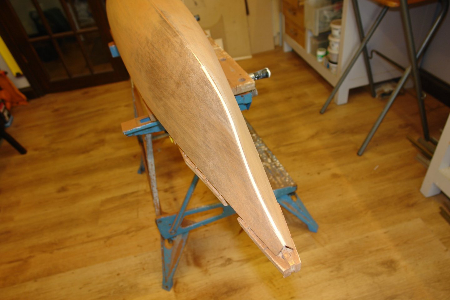
Then along the keel with more rabbet planks. The sanding stick isn't being glued on, it s just evening out the pressure on the plank being attached below.

A second rabbet plank was then attached over the first.
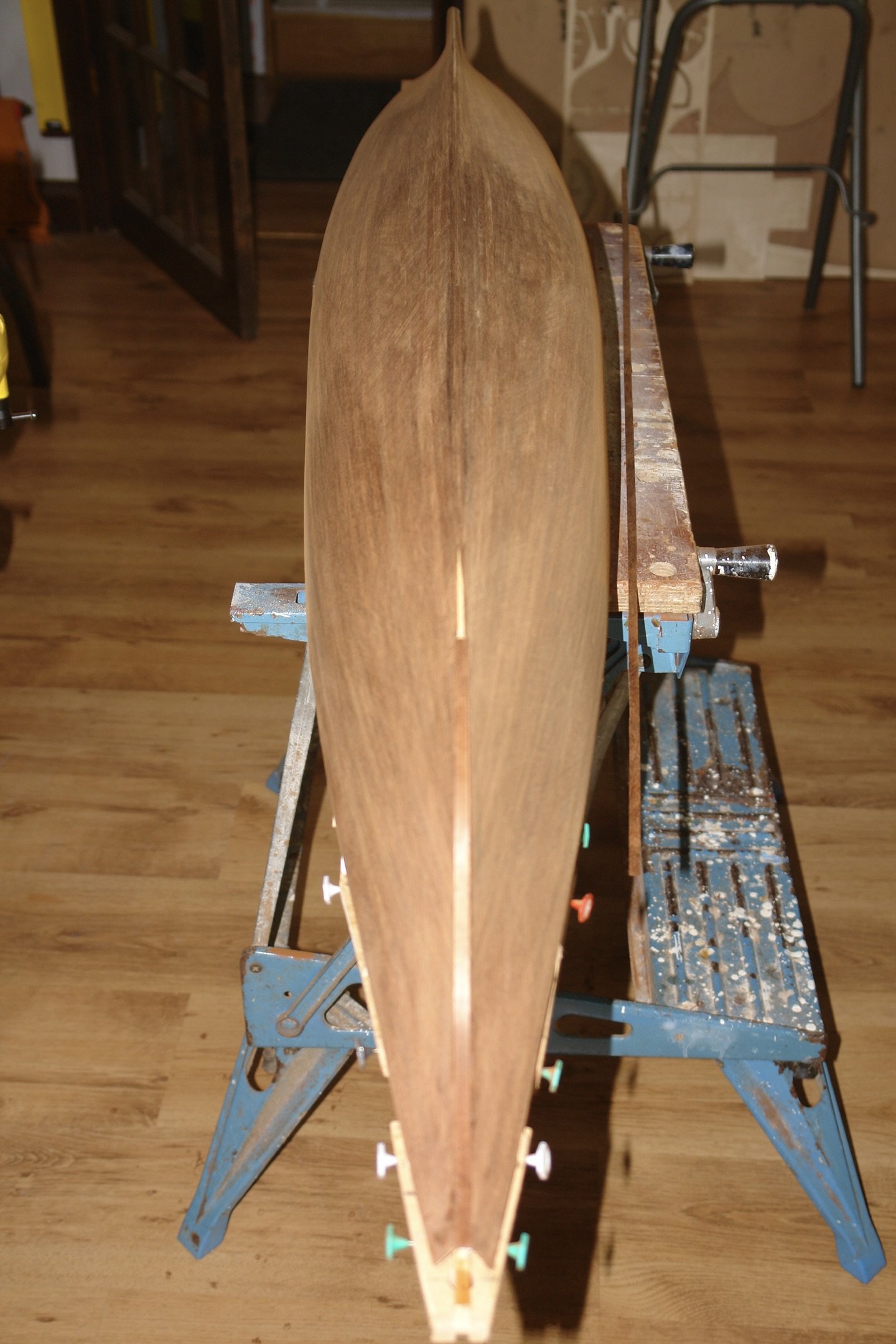
I then cut 1/10" strips of card and pasted these along the rabbet strips as a sanding guide. The keel has yet to be attached and this will be 1/10" wide and will fit on to the landing defined by the paper strips.


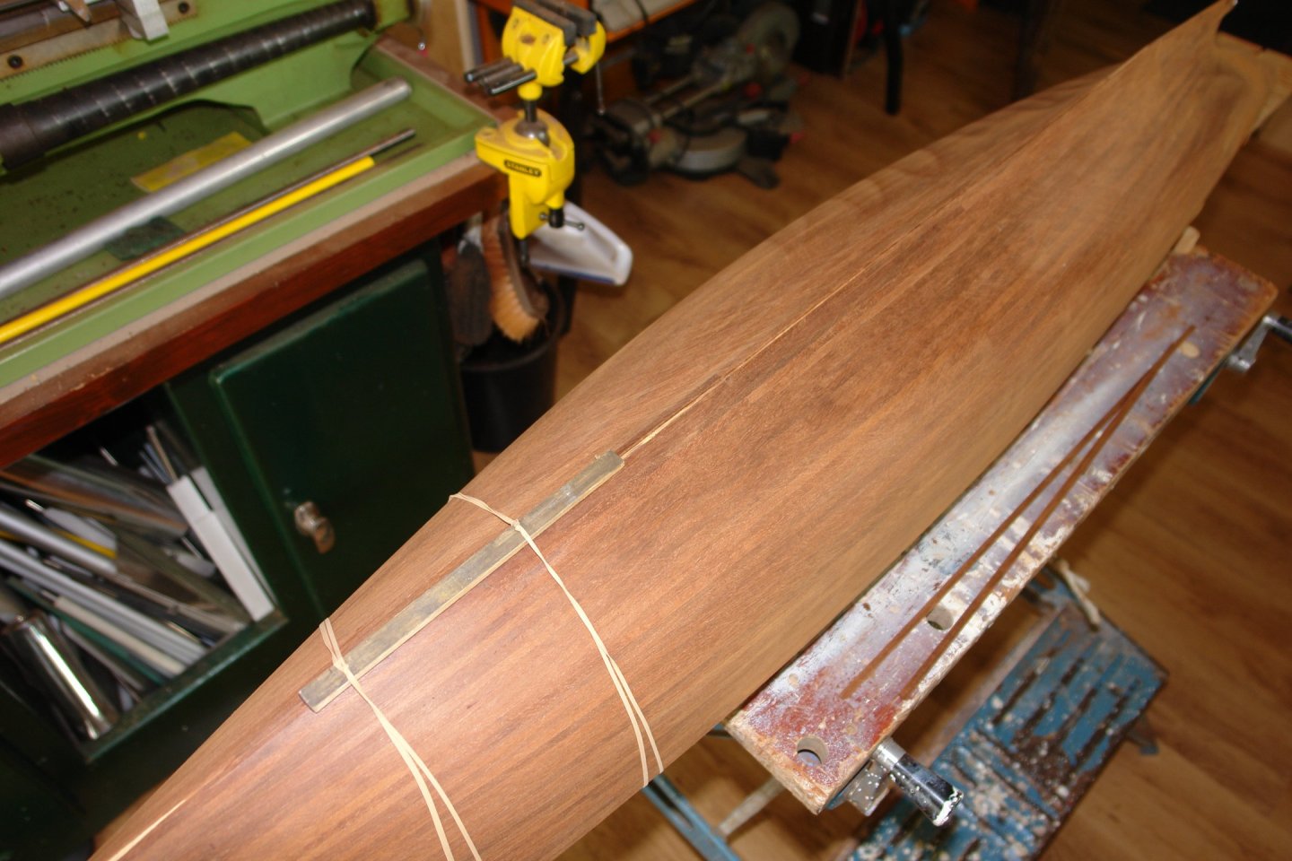
Then some more 120 grit sanding the fair in the rabbet strips and further smooth the hull. The planking is now of indeterminate thickness but holding up for the moment. No major planking gaffs discovered as yet.
Now the detached "keel end blunder" needs to be attended to. But that is a job for next time. The skeg block is finally starting the blend into the hull.
Thanks to everyone who managed to stick with it through that turgid story.
That's all for now folks!
-
16 hours ago, tmj said:
Hard brass is a pain, period! I hate working with the stuff unless I am forced to do so. Soft brass is soooo much easier to deal with!
It must be a personal preference thing. My preferred metal for machining operations is brass. I never like working with soft brass for any machining operation. Hard brass cuts beautifully and produces an excellent finish. Soft brass tends to push away from the cutting tool leading to binding and poor surface finish. This can be mitigated to an extent by keeping the tools very sharp. I only ever soften brass to ease bending operations.
-
-
18 minutes ago, Keith Black said:
I've not enough sand left in the glass to justify buying a lathe now.
Boys are never too old for new toys. And I bet in your head you are still young! Ask Bob his advice.
- mtaylor, Keith Black, FriedClams and 7 others
-
5
-
5
-
8 hours ago, Mark Pearse said:
The last part of the hull is the shaped piece that completes the propellor cutaway.
Nicely done Mark.
-
40 minutes ago, FlyingFish said:
But I'm not, so I did it using trial and error with some card, and then lots of back and forwards to the sander.
This luddite thought that was the only way to do it.
43 minutes ago, FlyingFish said:Vigilance into little 'models' of her to help raise funds for their rebuild at a local country fair.
Very good cause Andy.👏👏👏.
- FriedClams, Keith Black and AJohnson
-
3
-
-
On 4/21/2024 at 1:52 PM, navarcus said:
I have a 10" piece of 1/2" by 1/8" hard brass as a skeg for a Hartman Bunker Boat.
And it needs to be 3/4" lower at the middle to clear the prop -- sort of a short in height,
but long in length "Z". Is there a trick to how I bend it?
I think I recognise the picture immediately above.
I know that this may be a little late but to answer the question "how to bend hard brass"?
Brass is quite easy to bend but needs to be treated as follows.
Heat the area you want to bend using a blow torch until it glows cherry red.
Let the brass cool down to room temperature (no need to quench it).
Now start to bend the brass (you may need to create a jig to bend it round)
As you work the brass it will start to harden again - this is called work hardening.
Repeat the process of heating to cherry red followed by cooling - the brass will soften again and you can continue bending.
Repeat the heating / cooling / bending process until the desired shape is achieved.
-
1 hour ago, Keith Black said:
Craig, congratulations on the successful bow surgery.
Yes a nose job often improves the look.
Craig - The hull is looking very smooth and blemish free - clearly you build process worked very well. I guess from your comments she is going to be both a working and display model. I hope she doesn't get bashed up during playtime.
- Keith Black and mtaylor
-
2
-
Exciting Rob. She is a very handsome vessel but looks like quite a challenge. I'm sure you will make a treasure out of her.
- Javelin, druxey, FriedClams and 1 other
-
4


Vigilance of Brixham (BM 76) by FlyingFish - 1:32
in - Build logs for subjects built 1901 - Present Day
Posted
Handsome little fleet Andy. Let's hope they sell well. Presumably the buyer gets an authentication certificate?