


Cathead
-
Posts
3,522 -
Joined
-
Last visited
Content Type
Profiles
Forums
Gallery
Events
Everything posted by Cathead
-
Welcome! I just finished that half-hull kit and found it very useful. I'd strongly recommend going back and forth between the instructions and the official build log, as each have details and insights lacking in the other. Have fun!
-
 Everything looks crisp and consistent. I like how the red fits into the overall color scheme, too.
- 109 replies
-
- 1
-

-
- Finished
- Artesania Latina
- (and 1 more)
-
These are things they taught in the builder's yard, father to son, master to apprentice. Most of us are trying to make a shortcut across hundreds of years of accumulated skill and knowledge.
- 341 replies
-
- 3
-
-
- Sophie
- Vanguard Models
- (and 1 more)
-
The era is similar, so it seems reasonable to assume the engines followed the same general concept. Probably a lot bigger, though, given how large that vessel is. If you want to build engines, I strongly suggest getting a copy of The Western Rivers Engineroom Cyclopœdium by Alan Bates. It's rare but you can find it used in places, or you could always put in an interlibrary loan request. His companion volume The Western Rivers Steamboat Cyclopoedium would also be an excellent resource, and has some basic information on engine design and layout. You can also find some good visual resources on various websites by a basic Google search.
- 238 replies
-
- 1
-
-
- Robert E Lee
- steamboat
- (and 3 more)
-
Please tell me there's more than just that page!
-
Very late to this party but just have to add my awe and thanks for sharing this. It's giving me some inspiration for future projects.
- 189 replies
-
- 12
-
-

-
I can't tell if it's a trick of the lighting, but did you add a little color on the tarps beneath the ropes? Or is that just a shadow? Because it would make sense for the ropes to leave a little staining under their run. I can only echo the others in saying how fantastic that all looks, and that I want to remember that boat tarp technique.
-
Nice upgrades! Planking actually sounds easier to me, in terms of getting a nice smooth run through difficult curves, than trying to achieve that through sanding. And the result looks great. I definitely agree with adding the planking, too, there's little way to hide that plywood grain across scribing. I know what you mean about the architecture, the superstructures on these are so different from sailing ships and so much more complicated. This is certainly a more complex vessel than I've ever attempted. Looking forward to seeing how it comes together.
- 238 replies
-
- 1
-
-
- Robert E Lee
- steamboat
- (and 3 more)
-
I would've said the one on the right, but the middle is good too. Least of all the left-hand one.
-
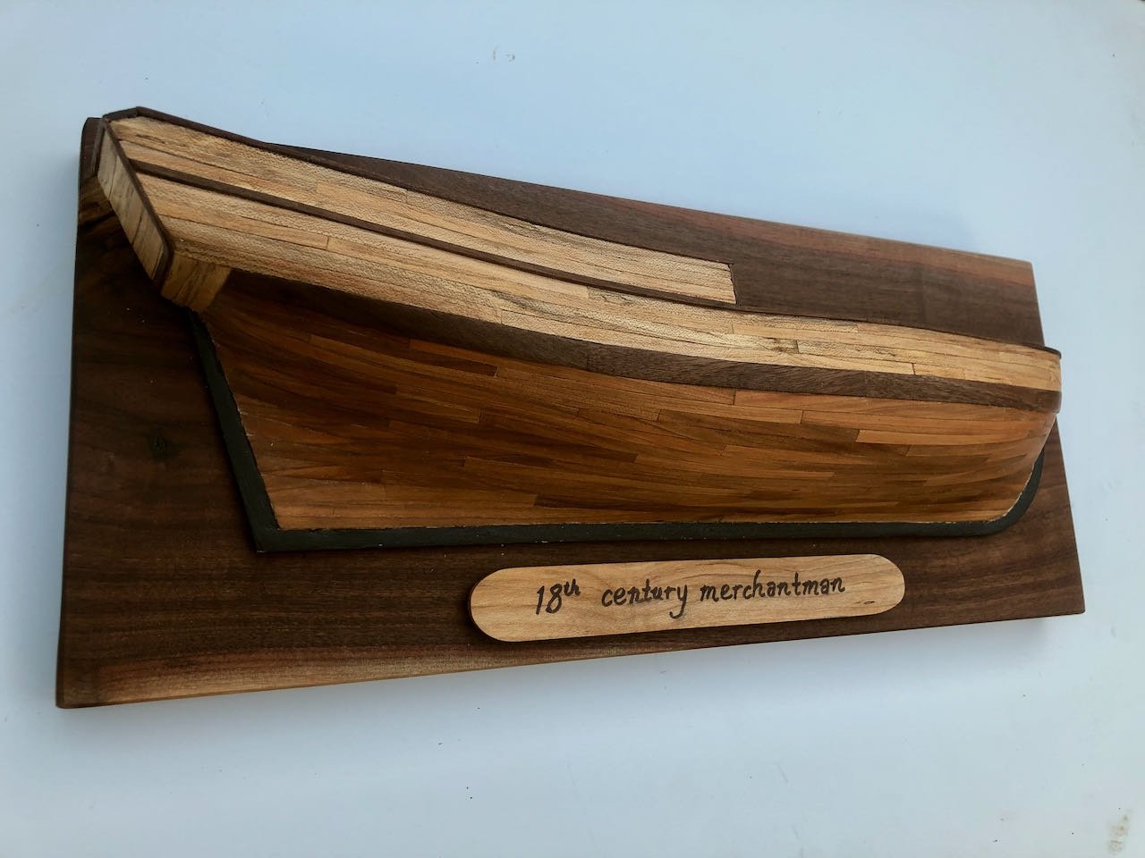
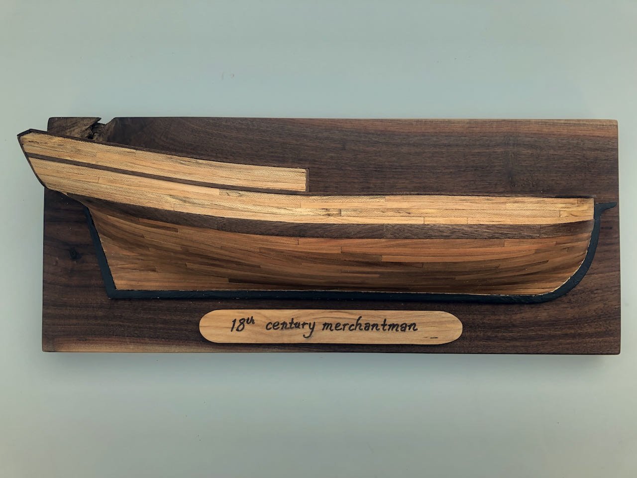
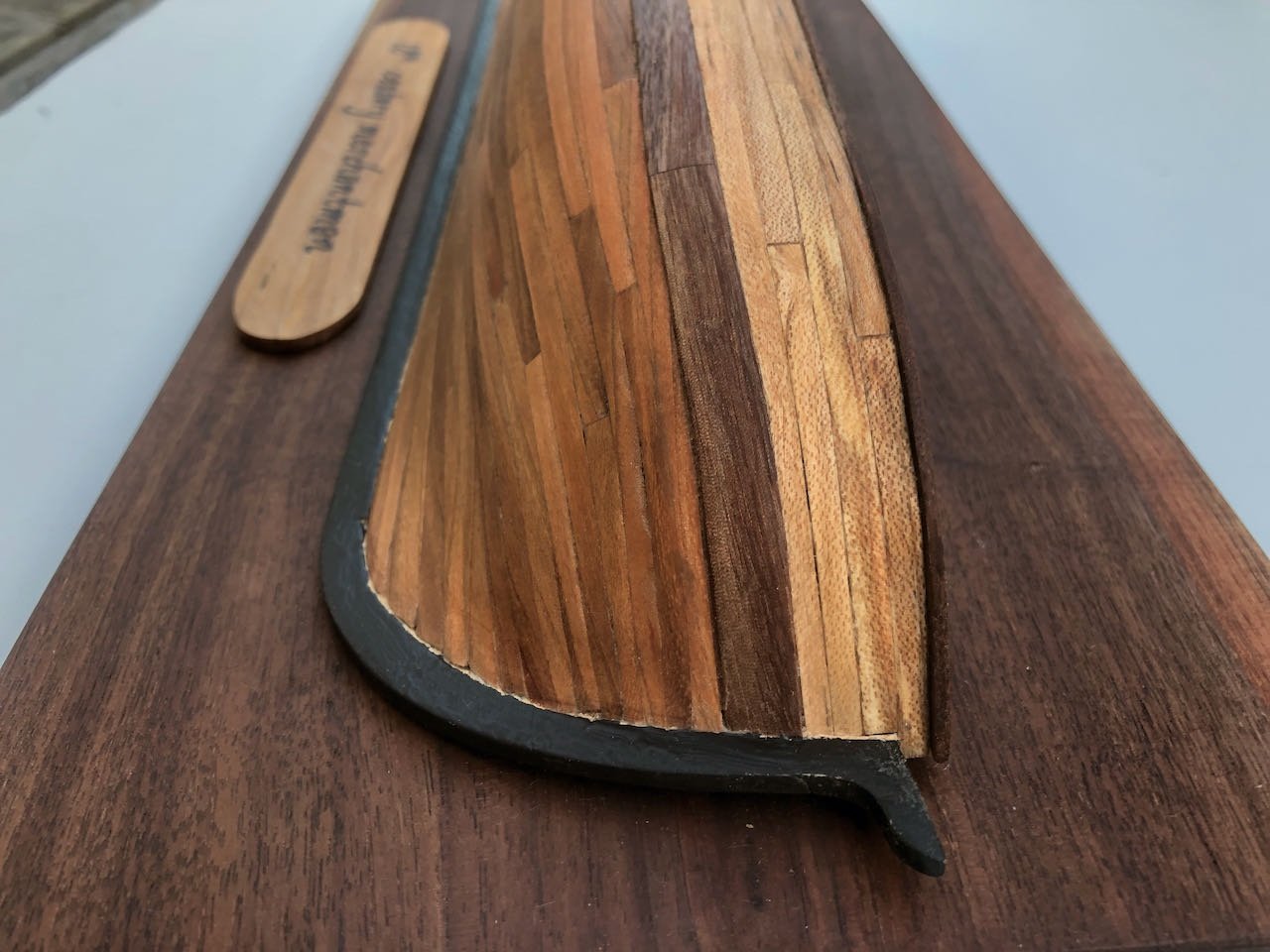
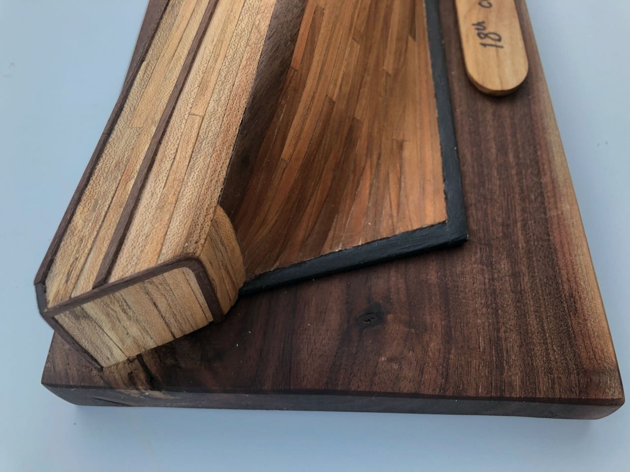
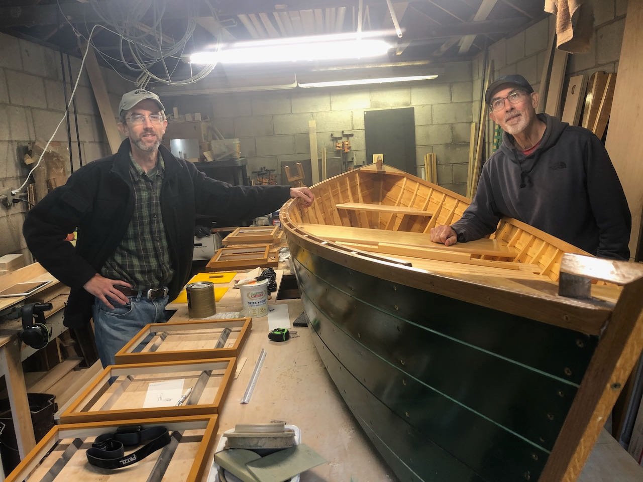
Surprise! The model is finished. I got wrapped up in finishing it and kinda lost interest in documentation along the way. I'm actually pretty pleased with the result, some serious sanding and multiple coats of wood oil really brought out the colors and contrasts in the walnut, maple, and cherry. I painted the exposed basswood keel black since it didn't look right raw against the nicer woods. The maple had some really interesting patterning that adds a lot of visual interest. For mounting, I dug out a slab of walnut from my wood shop with an interesting fault at one corner, and used a hand planer and orbital sander to smooth its face. It has a strong cup to it that I couldn't quite remove, meaning that the model doesn't sit quite flat against it, but this is only noticeable at close range and I don't really care. I glued some thick blocks between the model's framing and then screwed the hull to the mounting board from the back. I made a nameplate from maple, had my wife hand-letter it since she's better at that than me, and attached it using several small magnets. This way, if the model ever gets remounted, the nameplate can go with it. Here are a few more photos: This is a gift for my stepfather, now in his 70s, who has been a woodworker his whole life and is a true artisan in wood. I learned what skills I have, along with a love for building in wood, from him. He loves boats and fishing, and recently built his first wooden boat. The photo below shows us with that vessel in his small woodshop, where he still builds beautiful frames and other creations for sale at various art shows. He's never done model work and is fascinated by my projects, so this gift is pretty meaningful for me to give back to him. I shipped it off today (he's ~900 miles away in rural Western New York), since I won't be traveling for Christmas. Looking forward to his reaction when he opens it. The model wouldn't win any awards for pure craftsmanship, I can see its flaws as much as anyone, but it's attractive and interesting and will look great on his wall. Thanks for reading this log. It's probably not been the greatest resource for others who want to do this project, but I do recommend the kit as a great way to learn and practice planking skills. Making the wood myself had a serious learning curve that I hope to draw from in future, but I'm not sure how to convey those lessons in a way that would be useful to others (other than that a thickness sander or other way to ensure plank thickness would have been very helpful). Thanks to Toni and the NRG for developing this kit; my next project will be its cousin, the scratchbuilt capstan, for further practice in making and using my own wood.
-
Happy to follow along, this will be an interesting step up from your current project.
- 146 replies
-
- 1
-
-
- Harriet Lane
- Model Shipways
- (and 1 more)
-
That's a lot of shaping! Always up for another riverboat build.
-
This is a cool project, regardless of where it falls on the fanciful-real spectrum. Will be great to see how this progresses, as others have said.
- 341 replies
-
- 3
-
-
- Sophie
- Vanguard Models
- (and 1 more)
-
Nice start to what should be a neat model! Put very simply, the rabbet is where the lowest plank intersects the hull, usually defined with a groove carved into the keel so that the plank is slightly inset into the keel rather than just touching it. This thread here on MSW will give you some additional insights and resources, including a video on what this looks like in real life. MSW also has a whole section devoted to questions about planking, which includes this page with links to tutorials. Planking is a specific skill and is well worth studying up on if you haven't done it before; usually kit instructions aren't sufficient to teach the basic skill set and context needed.
-
Nice job, thanks for sharing. She looks lovely in her case.
- 127 replies
-
- 1
-
-
- Bowdoin
- Arctic Exploration
- (and 3 more)
-
This fits into a long-running theory of mine, that accuracy is not the same as realism in model-building. In other words, what is right isn't always what looks right. For example, a bright shiny railroad locomotive model almost never looks "real" even if the actual loco was that shiny. Making a model look "right" generally requires some concession to the human brain. Fantastic figures, as always. I forget if you've answered this, but what's the basis for the shoes? I've read accounts of sailors going barefoot at times, and wonder what you know about practices in this period.
-
Yes, as Mark says, that's the entire purpose of its existence. Moreover, since it isn't a "finished" model (few other details), any mistakes you make aren't really relevant to the final presentation. I would say that, for a teaching kit, I've found the instructions a bit confusing or incomplete in places, even though this is not my first planked hull. There's a lot of what in education we call "curse of knowledge", meaning the teacher has difficulty remembering and addressing the gap between what they take for granted and what the student actually knows. But that's true of virtually all normal kits, too, which tend to have it more strongly. I think the ideal approach would be to use this kit to learn or practice planking, but also to read/consult other references and guides on technique as well, using the physical kit to practice approaches rather than relying solely on its internal instructions. If nothing else, the original build log for this project has quite a few useful photos and details that aren't in the official instructions. But I would definitely recommend it as a learning or practice tool. For anyone who's wondering, I haven't given up, in fact I've made a lot of progress. But I haven't felt like taking photos and don't feel like what I'm doing really adds anything to the literature compared to all the other logs out there. I'll get some photos posted eventually but right now it's felt better just working on it in "silence". Using my own wood has been a major challenge and I'm not entirely pleased with the outcome, but it's certainly acting as the intended learning experience.
-
2021 NRG CONFERENCE
Cathead replied to kurtvd19's topic in NAUTICAL RESEARCH GUILD - News & Information
Just in case, here's the email I received: I'm sad to say I'll have to miss this live due to a commitment that's coming up. I assume it'll be recorded and offered for later viewing? -
I have nothing intelligent to add but feel the need to thank all the smarter people out loud for such a fascinating discussion.
-
Thanks for sharing that, I didn't know about it, but then I rarely make it to St. Louis being more of a Kansas City person. My wife, a former research scientist, was working on the Missouri when a barge broke free during high water and headed downstream, threatening various bridges as well as the research vessel. It was a scramble to corral the thing since the Missouri has very little navigation traffic and so very few resources available for such an effort.
- 1 reply
-
- 4
-
-
Congratulations! May you enjoy many years of gazing at it.
- 53 replies
-
- 1
-
-
- rattlesnake
- model shipways
- (and 1 more)
-
This might be crazy, but would it be possible to avoid the need for drilling and simply apply external details on either side of the planking? No viewer will ever be able to tell whether each rivet lines up through the plank if reasonable care is taken on spacing. This would potentially let you prefabricate roves and simply glue them in place, removing the need for complex clenching in tight spaces.