


Roger Pellett
-
Posts
4,519 -
Joined
-
Last visited
Content Type
Profiles
Forums
Gallery
Events
Posts posted by Roger Pellett
-
-
I have some old Floquil paints too that I would like to use. Does anyone know what solvent to use as a thinner as I assume that the “official” thinner is no longer available?
Roger
-
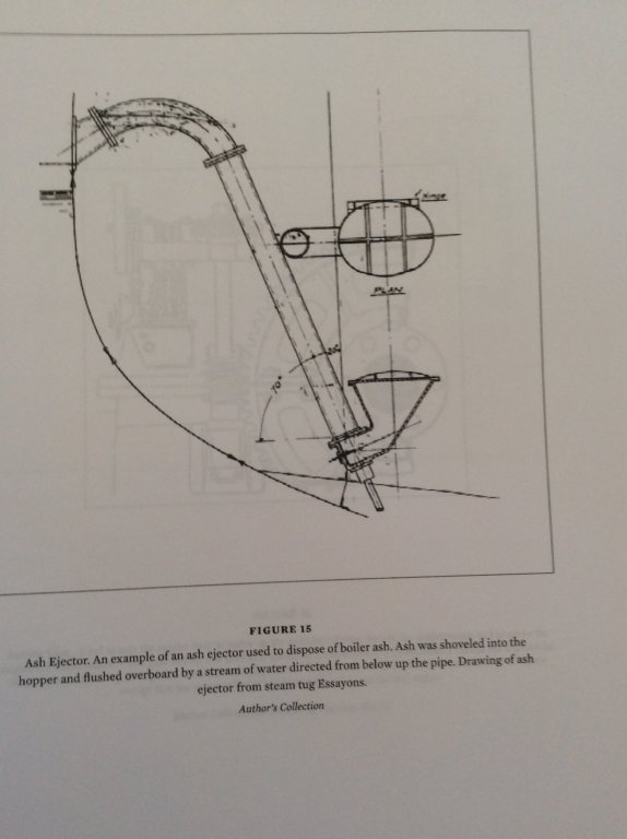
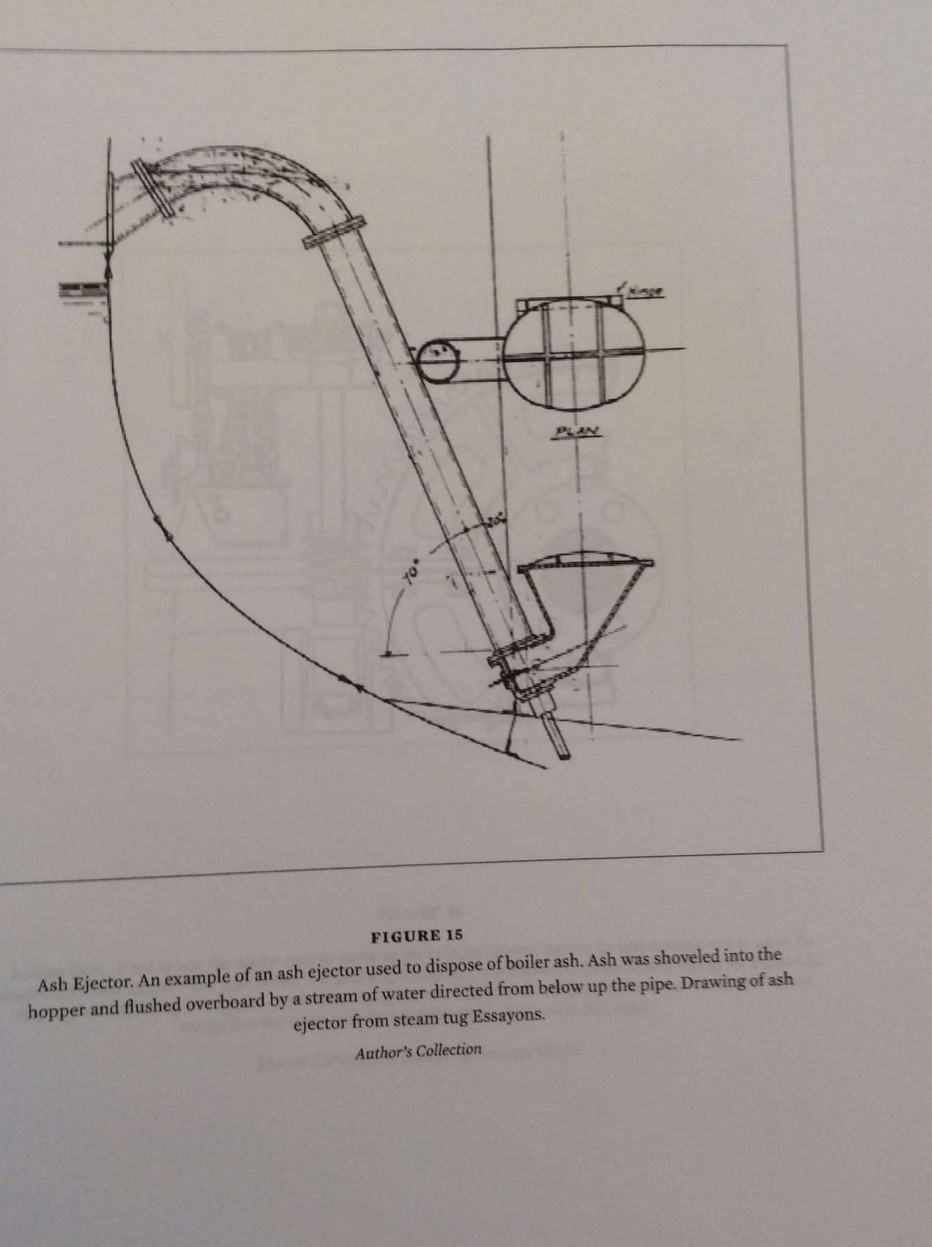
Ash and clinkers from the boiler fire pits would not have been stored on board due to the fire hazard. The usual practice on coal fired steamships would be to periodically rake out the fire from one furnace at a time on to the floorplates in front of the boiler, separate the clinkers, and then rebuild the fire. This was necessary as the clinkers would plug up the furnace grates and kill the draft. The clinkers would be hosed down and immediately discharged overboard. Where boilers were located below the waterline hydraulic “ash guns” were installed lift this refuse over the side. Illustration below.
This is functionally how how things worked. For the ordinary river steamer with the boilers on the main deck and the vessel’s sides open there is no reason why ashes could not have been dumped overboard from a wheelbarrow. For these gunboats, I don’t know what technology was available. I do know that the area in front of the boilers would have been plated over possibly on top of brick layer to withstand the heat from the hot clinkers.
Roger
- Cathead, Keith Black, mtaylor and 2 others
-
 5
5
-
In the coal fired pre-dreadnought and dreadnought eras coal was loaded from lighters into large cloth bags and hoisted on board. There are photos of sailors using hand carts to wheel these large bags of coal to the coal scuttles.
Roger
- Keith Black, mtaylor, Cathead and 1 other
-
4
-
If you have a small air compressor, an inexpensive “air eraser” (mini sand blaster) does a great job of preparing non-ferrous metals for blackening. It also adds some “tooth” to surfaces of metals that you plan to paint. I got mine at Harbor Freight and it seems to be surprisingly well made.
Roger
-
An easier and more accurate method for making open boats is to make and carve them inside and out in halves. The two half hull shells can then be glued and pinned to a central keel piece.
Roger
- Canute, mtaylor, SawdustDave and 1 other
-
4
-
On the model that I have been building I have been mixing my own paints from artist’s acrylics- the stuff that comes in tubes. Nothing very scientific, I don’t understand chroma, use of a color wheel, etc.
I start with a few basic pigments, bright red, van dyke brown, white, black, and grey. Combinations of these colors make attractive muted colors typical of the eighteenth century earth tones. I then mix these with matt medium (again by eye) and thin with water until thin enough to pass through my air brush. To work in my air brush, the paint must run freely from a mixing stick. If it dries in blobs it’s too thick.
Many (maybe six) coats are required to cover and to produce a good finish. Acrylics can be hard to brush as the paint must be flowed on. Brushing it out tends to leave streaks with the previous coat showing through.
Roger
- Canute and thibaultron
-
2
-
-
What were these vehicles used for? The large antenna looks like some sort of RDF unit. Is this so?
Roger
-
-
-
I bought my drill press 50 years ago and have never felt the need to replace it. The entire tool is built from cast and machined steel the only plastic parts are the adjustment knobs. If I was looking to replace it I would try to find a well built used one like a Delta.
Although the Morse tapered spindle will not tale side loads, I was able to buy an inexpensive collet chuck that locks onto the spindle via a threaded nut. With that accessory the drill press is perfectly capable of operating router bits.
Roger
-
This thread started while my wife and I were recovering from bad colds. Although the colds resulted from a Thanksgiving visit to our grandkids, they did highlight the importance of resporatory health.
I have been using power tools for 50 years and grew up in a house where my Dad used them. In fact after his marriage my Dad designed and produced model airplane kits to supplement his income during the depression. According to my father they were kicked out of the house that they rented because of the volume of dust produced by sawing up rough cut balsa wood into strip stock. (Making model airplane cement by dissolving cellulose plastic in acetone did not help their case either.)
Over the years, I have made half hearted attempts to control dust. I bought a good shop vac and I have one of those suspended Jet air cleaners. Neither is very satisfactory for serious dust removal from operating power tools. The problem is that dust quickly plugs up the filters, and it seems that whenever I want to use this equipment I don’t have the filters.
looking at the equipment above it appears that all of them feature some sort of separation device before the shop vac and according to the internet reasonably priced cyclone separators are now available. Using the shop vac to provide the vacuum in conjunction with a separation device to remove the big chunks before they can plug up the filter appears to be the key. My next shop upgrade.
Roger
-
In building these tools Preac would have used standard industrial bearings. Pop out one of the bearings, take it to your nearest bearing distributor and I bet that they can match it. Here in Minnesota we have branches of a company named Bearings, Inc but industrial supply houses like Grainger Supply also carry bearings.
Roger
-
-
Try this, Schooner Sunset: The Last British Sailing Coasters. Look it up on Amazon. I don’t have a copy but it would appear to be the British equivalent of the Chapelle fishing Schooner book mentioned in Frank’s post above. According to the review the book was written by a working sailor and includes much detailed technical information.
Roger
-
Another of Chapelle’s books not mentioned above is The Constellation Question, a published debate with Len Pollard on the authenticity of the relic vessel as one of the first US Navy frigates vs a Sloop of War built in the 1850’s with Chapelle of course arguing that the relic was built in the 1850’s not the 1790’s.
Recent scholarship has proven that Chapelle was right on target permitting a historically accurate restoration of the vessel. Fans (like me) of Chapelle, his work, and his writing will want to include a copy of this book to include in their collection.
Roger
-
According to the ASME historic landmark program the steam forging hammer was invented in France in 1839. They do not say when it migrated to the US but you are right the trip hammers used to forge anchors certainly could have forged this sort of ironwork.
My biography of Webb unfortunately says almost nothing about his yard operations, except that he did not build the machinery for the steamships that he built. After launch they were towed to an engine builder to be fitted with machinery.
Roger
-
A neglected topic in books and articles about wooden ships in the age of sail is the ironwork required to make them work.
Your posts do a great job of bringing this neglected topic to light.
1/8in at 1:72 scale equates to a real life dimension of 9in, so this was a large piece of ironwork.
It would seem that this would have been way beyond the capability of a shipyard blacksmith. If forged, would it have been within the capability of the water powered drop hammers of the time? Or would it have been an iron casting?
Roger
- EdT, Landlocked123, RichardG and 2 others
-
5
-
This model is someone's impressionistic idea of a ship, and its value is its unique style created by the builder. The more that you remove and replace the more that you destroy that style that you cannot replicate because you have your own style. I would avoid replacing anything unless absolutely necessary.
Roger
- Elijah, thibaultron, Canute and 1 other
-
4
-
Hi Eric, Yes, looking more carefully I see what you mean. The third frame could use a small shim. No worry, you did a great job and produced a model that you should be proud of.
Roger
- thibaultron, mtaylor, Cathead and 2 others
-
5
-
-
Three nice lobsterboats!
Eric, I don't believe that the reverse curve three frames forward of the transom is incorrect unless your kit actually included a lines drawing showing something different to compare your model to.
These boats require a wide stern and rather flat hull form at the after end to avoid trimming by the stern when carrying heavy loads and "squatting" under power. They also favored a rather deep hull form forward. Had this deep hull form been carried all the way to the transom, drag under way would have been greatly increased and flow to the rudder and propeller restricted. The reverse curve that you are seeing is the transition between the deep V foreody and the flat, shallow, afterbody.
Roger
- Canute, mtaylor and thibaultron
-
3
-
Some professional restorers claim that human saliva, not water on a Qtip is the best solvent for cleaning surfaces such as decks, deck furniture, and the small boats.
Roger
- mtaylor, thibaultron, John Allen and 2 others
-
5
-
Not just in the Phillippines! A good friend of ours wanted a "no frills" cabin on her Minnesota lake property. She contracted with someone in Ohio who transforms shipping containers into tiny houses. When the cabin was finally delivered she was unhappy with what she felt was a sloppy job and had to hire someone local to redo it.
Roger
USS ST LOUIS by thorn21g - 1:24 - POF - Civil War Ironclad - Gateway Model Shipcrafter's Guild
in - Build logs for subjects built 1851 - 1900
Posted
I realize that you are trying to make this model as accurate as possible but these details may defy solutuon. It would seem that two courses of action make sense regarding ash disposal.
To avoid misinterpretation by future museum visitors don't show any ash disposal system.
Or use Howard Chapelle's system of providing something in use at the time elsewhere. In this case, a mechanical hoist and an overboard sluice like Eric shows on his Bertrand model could have been used. The ash gun drawing that I posted comes from a drawing of the steam tug Essayons built in the early 1900's and I don't know if these were available during the Civil War era.
Incidently, the last coal fired steamship on the Great Lakes is the ex railroad car ferry SS Badger which ferrys passengers, cars, and trucks across Lake Michigan. The people that own and operate the vessel have been arguing with the EPA about the obvious problems of operating a coal fired ship with 1940's pollution abatement technology. To avoid dumping ash in the lake they recently installed conveyor system to move the ash to a shipping container on the car deck which can be removed and dumped ashore at the end of the trip. Different technology to solve the same problem 250 years later.
Roger