


Roger Pellett
-
Posts
4,501 -
Joined
-
Last visited
Content Type
Profiles
Forums
Gallery
Events
Posts posted by Roger Pellett
-
-
Kieth, A great project beautifully executed! Your deck structures are particularly impressive. For many years I have been thinking of building a 1:32 scale model of a Royal Navy Steam Pinnace. The bright finished cabin aft presents a particular challenge but your deck structures are an inspiration. I have several chunks of Mahogany salvaged from an old chair. It is at least 75 years old, tight grain and deep colored that I have been thinking of using for this purpose despite model building book advice that Mahogany is not a good choice. Your work proves the exception to the rule.
Roger
-
Charlie: Deck Finish. Several possibilities come to mind. The most obvious is Testor's Dullcoat, available at hobby shops and big box craft stores. This stuff comes in a spray can and is foolproof. You might also look into hardware store spray can clear finishes even though they may be branded as enamels, they behave and smell like lacquers. Further afield, on his USS Essex CA-9 post, daddyrabbit is discussing use of a sprayable floor finish. We recently had a maple floor installed in our family room. It was finished with a matt finish floor finish. I believe that this is a water based polyurethane. It is perfectly transparent. I think that this would be similar to the material that daddyrabbit is talking about.
Roger
-
I have never used Minwax Poly and have never used any wipe on finish so I can't comment. As discussed elsewhere, an advantage of a true laquer is that it dissolves itself. That is a second coat actually dissolves the coat beneath. Varnishes, either polyurethane and alkyd resins cure and become chemically resistant to the next coat. These very different characteristics are either a good or bad thing depending on what you wish to accomplish. If you are trying to repair a minor Boo Boo, an over spray with laquer will blend in to the previous coat. On the other hand, when using laquer based paints, you do not want adjacent colors to react with each other.
See Julie Mo's build log for the J Boat Ebdeavour for a discussion of laquer.
My model was unrigged and built from three naturally finished woods- pear, box, and holly. When I finished building it, I hung it from a hook and sprayed it all over with clear flat laquer. It has just passed 1/3 of its 100 year lifetime and is holding up well.
Roger
-
Charlie
Deck finish: The decking on my model of the New York pilot boat Achilles/ Express is 35 years old. It is holly that a co-worker gave me after pruning a tree in his yard. It has "no finish." Just a light coat of flat laquer sprayed on with an air brush. I had a paint store mix mu up some but Dullcoat would work as well. I don't remember how I simulated the caulking. The planks are 1/8in wide and the fastenings are bamboo. Roger

- mtaylor, CharlieZardoz, coxswain and 2 others
-
 5
5
-
Julie,
Your J Boat at 1:35 is a large model and unlike a square rigged craft you will only have four sails; a main and three headsails. You will also have relatively little rigging Compared to a square rigger. Your mainsail will be huge. Therefore, no matter how skillfully you model the sails you risk having your model looking like a pond yacht.
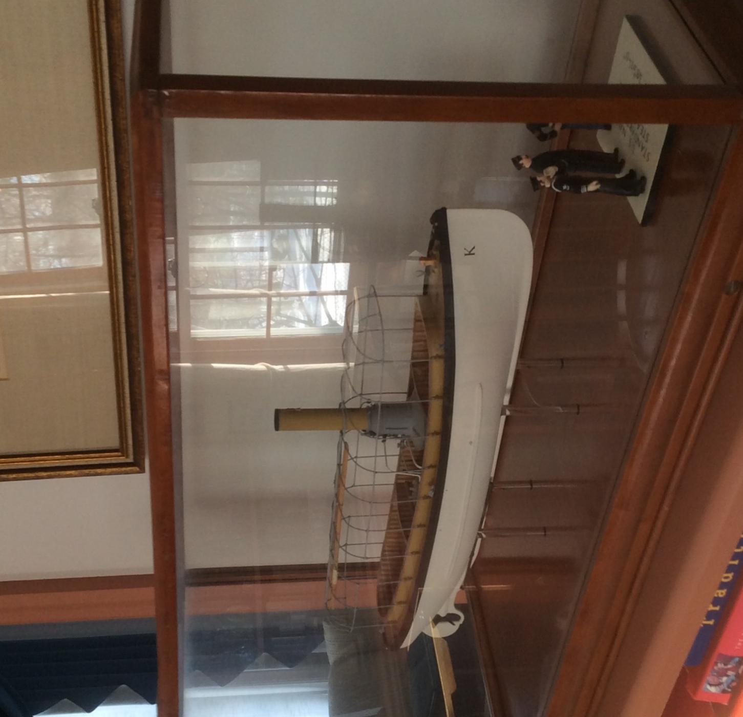
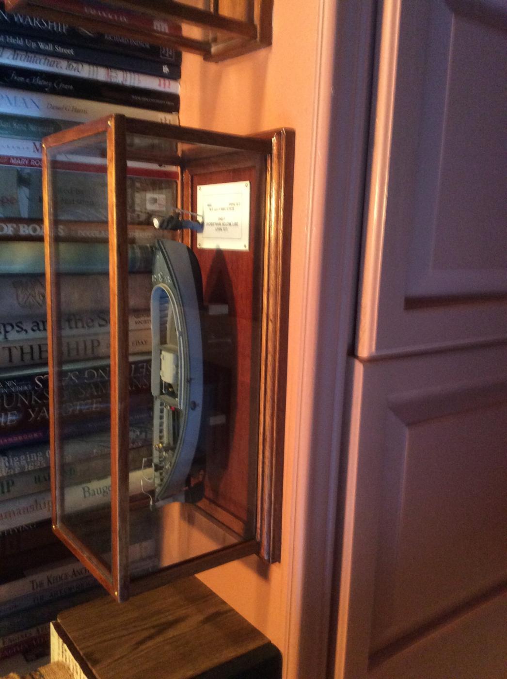
I have seen the models in the Herreshoff Museum and the New York Yacht Club's model room as well as a stunning J Boat model that was offered for sale in the Mystic Seaport's model gallery. In all cases, the models were without sails. In these cases, a lack of sails accentuated the rigging and spars. Much of this detail would have been hidden by sails.
Roger
- Julie Mo, thibaultron and mtaylor
-
3
-
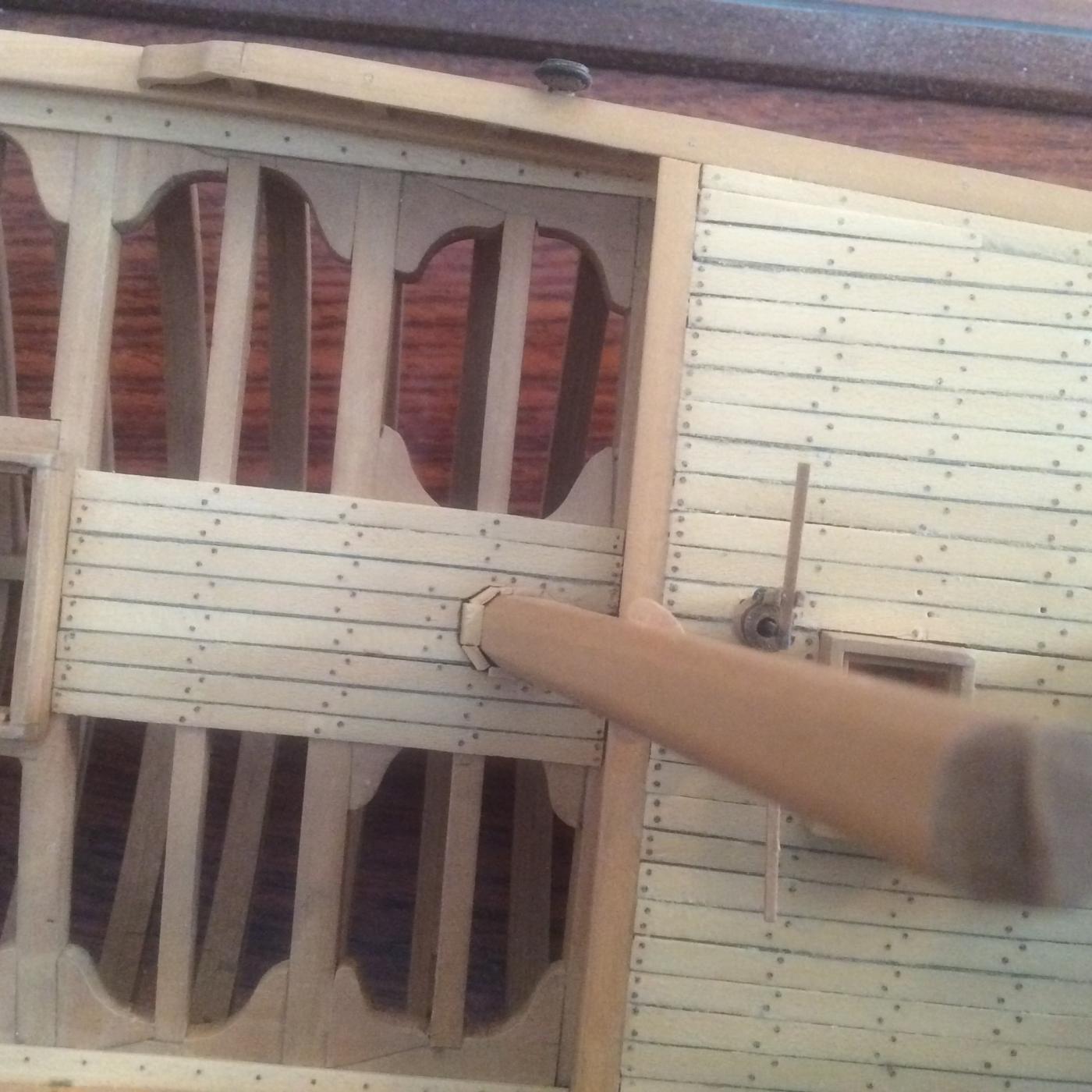
Copper sheathing was nailed on with flat headed sheathing tacks, not bolted. The large wart like bumps shown above appear to be way over scale. I con't know exactly how large the heads of a sheathing tack were but a 1/2in diameter head at your scale would only be 1/128in. A more realistic representation would be a row of tiny impressions.
Roger
- mtaylor, Canute, EricWilliamMarshall and 1 other
-
4
-
Kieth
I'm not doubting that it is a model of the Tennessee. I think that the builder had no idea what the hull actually looked like.
The book includes quite a bit of text regarding this class of high speed cruisers, their condemnation by the Navy and the rebirth of some of them as large, slower frigates. Specifically, the book includes a lines drawing and inboard profile of the Tennessee. It does not include refit by refit photos.
Roger
-
Volume 1 of Canney's "Old Steam Navy" has material on Tennessee and her predessor Madawasca including a lines drawing. The hull of this model bears little resemblance to the hull of the actual ship. It would seem that the builder of the model had a distorted perspective of the actual vessel like some of the early paintings of Western warships by Japanese artists.
Roger
- Keith Black, Canute and mtaylor
-
3
-
-
Assuming that this thread can be broadened to Western Rivers Steamboats, I would include the HO scale kits of upper Ohio River craft sold by ???. I can't remember the name of the vendor but he was at the Mystic NRG conference. I thought that these models were highly accurate especially the model of the small "pool boat." Similar but smaller than the W.P. Snyder preserved in Marietta, Ohio. Hopefully someone else can identify the vendor.
Roger
-
I have two sets of tweezers, surgical forcips, and sissiors from trips to the emergency room. One from a not so near miss table saw accident and one from a kitchen knife accident that my wife had Thanksgiving a year ago while visiting our son out-of-town. Each time, the surgeon asked if I was a fly fisherman. Apparently, some hospitals throw them out, others autoclave them for reuse.
I realize that I am the only accident prone ship model builder on this forum, but If you just happen to be in this situation, it never hurts to ask.
Roger
-
Re: Spencer Mast
Readers interested in this topic may wish to refer to the "American Warships for which there are no plans....." Thread in the Nautical History section. On the next to last page there are two old photos of the deck of the frigate Santee. These show Spencer masts on mizzen and main masts. One appears to be seated into a gooseneck fitting. The fitting itself is unfortunately not visible. The main mast Spencer appears to be seated into a boss protruding from the fife rail that runs behind the mast. Good views too of the Spencer mast hoops.
Roger
- Canute, Stuntflyer and mtaylor
-
3
-
-
Maury,
If you have not already done so, Google "anchor hoy". You will find a photo of a model of the anchor hoy that you are building sold by American Marine Model Co. This model was built by Eric Ronnberg, an excellent model builder and maritime researcher. On this Model the spencer mast runs clear to the deck where it is secured into a hole in a block of wood. That is also the simplest solution and simple is usually better.
Roger
-
My models are generally built from laminated lifts layed up from buttocks. I build two half models and then put them together using pre drilled locator pegs to ensure accurate alignment. I have built one plank on frame model, the NY pilot boat Express using the Hahn method but the rest of my models have carved hulls. The plank on bulkhead method does not appeal to me.
The little spokeshaves are perfect for carving and fairing these models.
Roger
- PeteB, keelhauled, Canute and 2 others
-
5
-
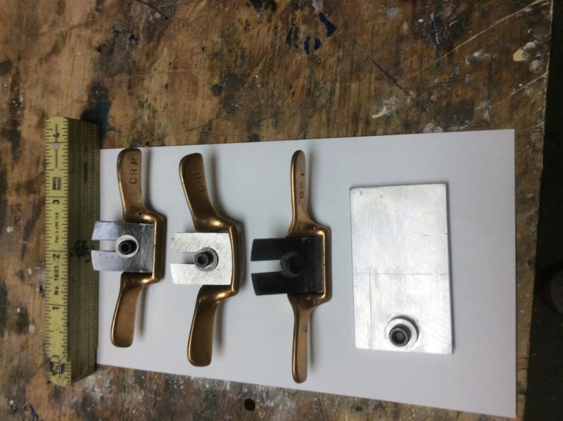
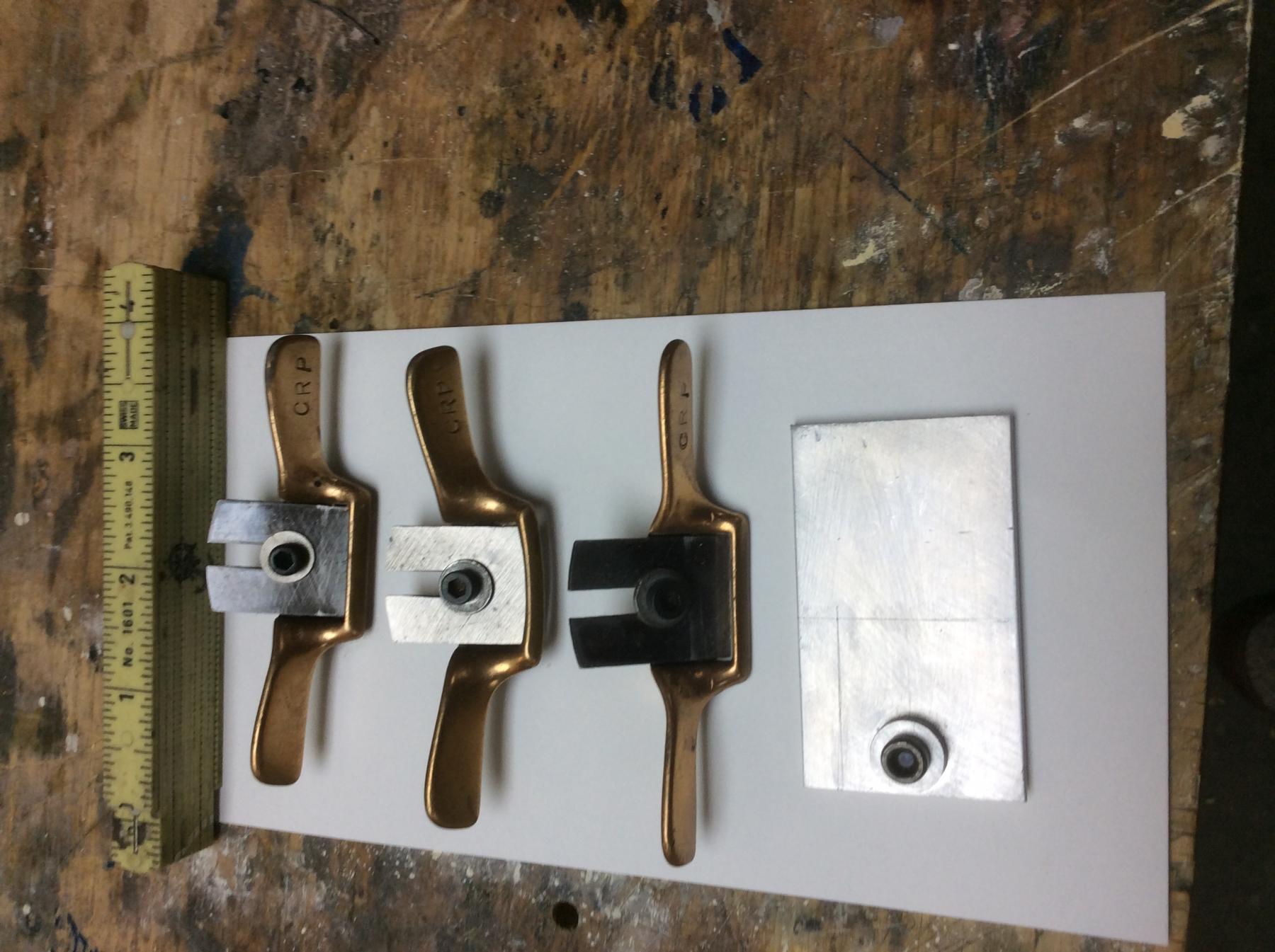
For me, the two fingered holding approach would be difficult. In general, tools with larger handles are better for me as I have lost some strength in my hands due to a complex health problem and maybe just getting older.
The attached photo shows a set of miniature spoke shaves that I do find useful. They are gripped between the thumb and forefinger- both hands and pushed or pulled. I bought them in 1965'after seeing them used by professional model builders at the University of Michigan''s Naval Architecture Towing Tank. I believe that the set cost less than $5. They are no longer available new but occasionally show up on EBay. I made the simple aluminum fixture ho hold the small blades in my honing guile.
Roger
- Mike Y, CaptainSteve, Canute and 8 others
-
11
-
The chisels are finely crafted tools, but I don't see the point. The chisels are not miniature in width. Unless I am missing something they are offered in standard widths- 1/8, 1/4, 3/8 in. As reklein points out the small handles make them awkward to use ( at least for old guys like me) lengthen the handles and they're just short shanked full sized chisels.
Can anyone explain?
Roger
-
Actually, there is a lot of published information available on the rigging of the Fair American. The Nautical Research Guild published a series of articles twenty years ago or so on this topic. My recollection of the articles is that the Naval Academy's model was rerigged in the 1920's by Charles Davis who included many anachrostic features such as a dolphin striker not used at the time when the ship was in service. Therefore, if you are making a model of the Naval Academy model the rigging doesn't represent actual practice anyway. Reprints are cheap. Look on their web site.
On the other hand at one time the MS model kit included a monograph written by Eric Ronnberg. Eric is a thorough and meticulous researcher. And if your kit still uses Eric's plans and instructions I would be surprised if a lot of information is missing. If not, you might want to track down Eric's monograph and plans.
Roger
- Gregory, thibaultron and mtaylor
-
3
-
Some time ago as part of a build log of the USS Constitution, someone was building one of these "cages" and doing a beautiful job of it. Actually, I believe that these are frames for supporting canvas canopies for bad weather. He left them as bright brass as they are on the real size USS Constitution today. These ships had very large crews with plenty of time on their hands to polish the brass.
Roger
-
A "must" attachment for the Sherline mill is their Sensitive Drilling Attachment useful for drilling holes with very small wire sized drill bits. This is particularly useful for making blocks and deadeyes and essential if you don't have a drill press. I don't know if the other mills that you are considering can be used with such an attachment.
Regarding size of milling cutters. With the Sherline mill and the right collets you can always use the smaller mills (1/8in shank) but with the smaller mills you can't use the larger ones.
Roger
-
If the Proxxon milling machine is limited to cutters with shaft diameters 3.2 mm and under that is a major limitation. I have a Sherline Milling column that converts my Sherline lathe for milling. I have a 3/8in tool holder that (I think) came with the column and a set of milling collets that I bought. This allows me to use standard 3/8in and 1/4in spiral end mills available from any local industrial supply house.
Roger
-
I agre with Chuck, I just made some thimbles from standard hobby shop K &S brass tubing although I used a somewhat different method- I hadn't seen his post at the time. From some solid brass round bar I machined male and female dies. The male die was just a cylinder with a nipple machined on one end. The diameter of the nipple a slip fit for the id of the brass tube thimble stock.. I left a small radius between at the shoulder between the nipple and the round bar. As long as the diameter of the round bar is larger than the of of the brass tubing the actual diameter is unimportant.
The female die was just the same round bar stock with a hole center drilled. The diameter of rhe hole a slip fit with the male die nipple.
To make,a thimble,I first chucked the tubing in my lathe's head stock with only a sixteenth or so protruding. I chucked the male die in the tail stock. After turning on the lathe I fed the male die into the hole in the tubing. When the shoulder between the nipple and the round bar came in contact with the tubing it flared it. I then parted it off with a razor saw.
I then reversed the piece of tubing on the male die so that the flared end was pointing towards the lathe headstock, and I chucked the female die in the headstock. I started up the lathe and fed the male die into the female die, flaring the second end.
It was much easier than it sounds.
Roger
- mtaylor, Canute and Bill Tuttle
-
3
-
-
Altair 1931 by KeithAug - FINISHED - Scale 1:32 - schooner
in - Build logs for subjects built 1901 - Present Day
Posted · Edited by Roger Pellett
The name Mahogany, at least here in the US, is used for several different tropical hardwoods. Some if the stuff is pretty poor, stringy and course grained. I believe that the real stuff is Honduras Mahogany, very difficult to find today. Mahogany salvaged from old furniture is therefore like gold.
Roger