


Roger Pellett
-
Posts
4,519 -
Joined
-
Last visited
Content Type
Profiles
Forums
Gallery
Events
Posts posted by Roger Pellett
-
-
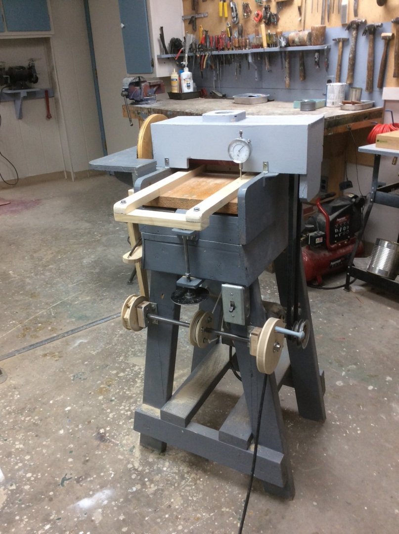
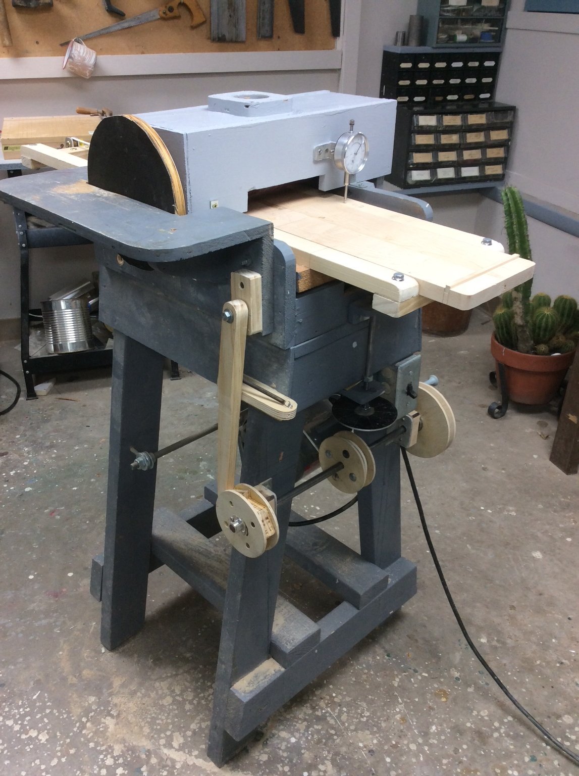
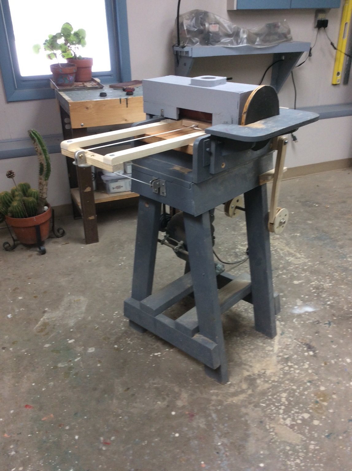
The machine upgrade is finished and works well. The piece to be sanded rides through the machine on a sled. The hand wheel on the right hand side turns the drum on the shaft, winding the white cord to pull the sled through the machine. The sled can accommodate wood up to 15in long. This means that I can sand a 40 to 60 ft piece at the scales that I usually work to. Kickback protection is provided by the ratchet and pawl on the left hand side of the machine.


- Ron Burns, Canute, Keith Black and 1 other
-
 4
4
-
My longboat model built to plans in May’s book includes three fixed thwarts; one in the bow, one at the mast partners, and one just forward of the stern sheets. These fixed thwarts are each fastened with knees into the rising strake. The other thwarts are loose. Both the NMM “Medway” longboat model and the longboat model in the Krigstein Collection are arranged the same way.
By the 1840’s navies had switched to launches instead of longboats and the US Navy specified that all thwarts In launches be loose. The ends of the thwarts were to be reinforced with iron plates and were to be secured with removable iron pins through holes and passing into iron brackets.
-
According to what I read, during a subsequent excavation project in the ‘60s they did make a fiberglass cast of part of the ship. That might have been what you saw.
- thibaultron and mtaylor
-
2
-
Art,
I hesitate to post this since you’ve already spent $100, BUT, here goes.
A number of years ago, I got involved rebuilding wood canvas (Old Town) canoes. These involve a lot of steam bending. After jury rigs outdoors I finally set up a system that would be safe to use indoors.
Your steam generator will work well. I used a Wagner PowerSteamer wallpaper steamer that is the same thing that you have, just a different color scheme.
After trying PVC pipe as a steam box I found that it would not withstand the heat from the steam. It sagged badly. I replaced it with a wooden box made from 4 1”x4” boards nailed together. With a hinged lid on one end and a block of wood capping the other. A galvanized threaded flange was fastened to the bottom and a threaded nipple was screwed into the flange that mated with the hose from the steam generator. A small hole was drilled into the bottom as a drain.
The hinged door allowed me to quickly open the box to pull out wood. The steam can burn you quickly so you will need some sort of tongs. Another advantage of the wooden box is that it leaks! This allows circulation of hot steam within the box and ensures no buildup of pressure within the system.
If you have adequate circulation in and out of the box, I don’t see a need for either pressure or temperature gages. Water at atmospheric pressure boils at 212F, and you don’t want a closed system.
Roger
-
We watched it last night too and enjoyed it. After the show, I dug out A Nautical archeology book and found out that the site was excavated again in the 1960’s.
- mtaylor and thibaultron
-
2
-
Mr Bluejacket’s Red Jacket! Wonderful work!!
-
Everybody’s work habits differ, but I scratch built several models while managing a demanding career with constant business travel and helping my wife with our two children. Some tips:
Unlike remodeling your bathroom with relatives expected to visit next month, there’s no schedule. If it takes you twice as long to build the model than you think it should, no problem.
Work in small blocks of time; an hour or even a half hour. If your kids are young enough, nap time becomes your modeling time.
The number of hours you spend building the model don’t matter. This is not a business. What does matter is that you manage your time so the things that you and your wife agree need doing get done.
A key to all of this is a dedicated work space where the model can sit undisturbed between work sessions.
At least when you are working on the model you’re home. You’re not spending 4 hours with three buddies on the golf course. When I was a toddler, over 75 years ago, my father built a model of the Clipper Ship Flying Cloud. Watching him work on it is the only memory that I have from that age. Although he died many years ago, I have the model. I cleaned and restored it and built a glass case for it. By building it he inspired me to follow him and to get the education that would serve me for a lifetime. If you have children, don’t underestimate the effect that your model making activity could have on them.
Roger
-
Yes, industrial and hospital applications use autoclaves to contain pressure above atmospheric thereby raising steam temperature. Simple steam boxes do not do this.
The temperature difference between dry and moistened wood is also striking.
- mtaylor, thibaultron and Canute
-
3
-
Steam Temperature: Water at standard atmospheric pressure boils at 212F (100C). If you live at a high elevation like Denver, Colorado the boiling point is less. There are two ways to increase steam temperature both used in power plants but impractical for ship model builders:
Increase the pressure at which the water boils. That’s how a pressure cooker works.
Heat the steam after leaving the pot that it boils in. This is called superheating.
That’s it, you can’t fool Mother Nature.
Steam coming out of a pot of boiling water contains more heat energy per unit mass than the steam water mix still in the pot but the temperature of the boiling water in the pot and the steam coming out of it are the same. Heat transfer is driven by temperature difference, and conductivity. Water has better conductivity than steam. A small piece of wood in a pot of boiling water will heat faster than one held in a jet of steam.
Roger
- Bob Cleek, thibaultron, Canute and 1 other
-
4
-
Boat and color looks good, Brian
- Cathead, J11, Keith Black and 1 other
-
4
-
Steven,
The Boat turned out well!
Roger
- mtaylor, Keith Black, egkb and 2 others
-
5
-
Consider the customers likely to use hardware store stains like Minwax. Most woods that they are likely to come into contact with are open grained Woods like softwoods and red oak. These stains are often used by do it yourselfers trying to make these
 cheap woods look like something more expensive. These stains are good enough to satisfy these customers.
On the other hand, anyone using stain on a scratch built model is using high end woods; maple, cherry, holly, apple, pear, and yes boxwood, Castillo or the real stuff. The reason that these woods are used is the same reason that they don’t take the mass market stains. They are hard and dense with a
tight closed grain structure.
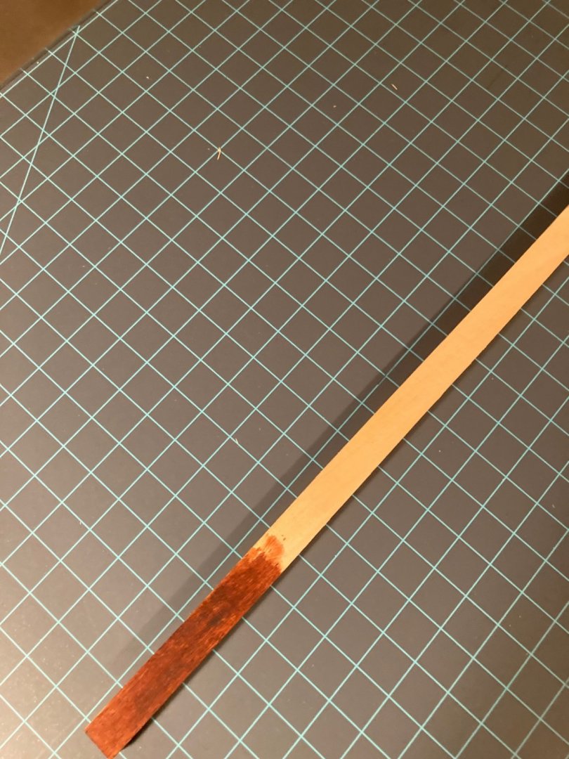
If for some reason you want to stain these, something that will penetrate this tight grain structure is required. The picture above shows a piece of boxwood stained with Fiebing Dark Brown Leather Dye.
Oops, picture showed up in the wrong place!
-
The wood that Tony is using is not the same as that sold commercially today.
Old wooden drafting tools were manufactured from “real” boxwood. I’ll leave the scientific nomenclature to others. This is light yellowish tan wood, very dense and hard. When cut with a sharp blade it takes on a polished surface. This wood is commercially unavailable today. Since wood stain needs to penetrate the surface, it’s not hard to understand why Tony is having trouble staining it.Today, model builders eager to build “boxwood” models are using Castillo a different species that the trade calls boxwood. I have no experience using this wood.
The typical mass market stains are ground pigments suspended in a liquid, often linseed oil. These work on open grained woods but do not penetrate hard, dense, tight grained woods. A better choice would be a dye. For a recent project, I stained pear wood blocks with dark brown leather dye, obtained from a local shoe maker. True boxwood might be harder to stain.
Roger
-
Jaager,
Thanks for your clarification. My post was intended to introduce Neophytes to the mysteries of ship drafting and was based general principals. My Naval Architecture education occurred in the early ‘60s, prior to the dawn of CADD. We were still required to manually make a lines drawing from a table of offsets with the finished drawing India ink on vellum. What a mess! The ship in question had a steel hull and if lines drawing sections were a multiple of frame spacing we had no way of knowing.
I certainly agree that there were many framing conventions in the wooden ship era most of which were certainly connected to construction techniques, a subject usually ignored. I agree that many ships were built by lofting a minimum number of frames and then adding filler frames between, all dubbed to produce a fair hull.
This may account for differences in performance of sister ships built to the same lines.
-
Two out of three plots, waterlines and body plan shapes plus bow and stern profiles, define the shape of the hull. Modern naval architects add buttocks and diagonals to check the fairness of the hull.
Do you plan to redraw the lines? Relying on the downloaded image without making a new drawing is unlikely to yield a set of frames that will produce a fair hull.
-
OK! Naval Architecture 101
The hull’s shape Is defined by a specialized drawing called a “lines drawing.” If you’re familiar with mechanical drawings, the lines drawing is an orthographic projection showing the hull in three views; the top view is called the “half breadth,” the side view the “sheer,” and the end view the “body plan.” To save drafting effort since the hull is symmetrical only one side of the hull is shown on the half breadth drawing. The body plan appears to be odd to some as one side shows the view looking forward and the other looking aft.
The hull’s shape is further defined by contour lines that appear as curves in one view and straight lines in the other two. The half breadth shows a series of curves known as WATERLINES running fore and aft. The body plan shows the SECTIONS as curves, and the sheer shows a series of curves known as BUTTOCKS. Buttocks often do not show on very old drawings so they need not concern us.
For hull classic Eighteenth hull forms, the waterlines are (mostly) convex arcs that come to a point at the bow and stern. It therefore stands to reason that there is a point where the waterlines are at their widest point. The section at this point is called the “deadflat.”
It is also possible that the hull shape will feature an area where the body plan sections are identical. This would naturally happen at them widest area of the hull. Modern day Naval Architects call this a parallel midbody. This would mean that there is more than one deadflat section.
Roger
-
Are these EU regulations that will be relaxed by Brexit?
-
AP and FP stand for after perpendicular and forward perpendicular. They define the dimension, length between perpendiculars or LBP. In simple terms LBP is the “length that floats the boat,” although there are hull forms where this is not true. In making a lines drawing, the naval architect first draws a baseline, then the FP and AP. The space between is then divided into stations. These stations do not necessarily match frame locations as frame shapes were developed from the full sized lines layed out on the mold loft floor.
Roger
-
Hi Bill,
My parents lived in the Vermilion Lagoons from 1979- 1986. Looking down the lagoon from their kitchen, the Inland Seas Museum was atop a small hill across theVermilion River. My father and I visited the museum when they still had the original ink on linen drawings. There was also an attempt in the 80’s to start a model ship club there, but I was living and working at the other end of the state in Marietta and only attended one meeting.
Your plan catalog was quite a project. It’s a shame that it is not more widely distributed. While volunteering for the Whaleback Steamship SS Meteor Museum, I had them buy the two microfilm rolls of American Steel Barge drawings from BGSU. We then had them scanned and saved on CD’s. In 2007? I wrote an article cataloging them that was published in the Journal.
Fraser Shipyard in Superior, Wisconsin recently donated their stash of obsolete drawings to the Superior Branch of the University of Wisconsin. A young lady who worked with me on my Whaleback Ship Book, has cataloged them and published an article recently in the Journal. They may have some drawings of Edna G. Edna G. Still exists afloat in Two Harbors, MN just up the North Shore of Lake Superior from where we live. She is owned by the Lake County Historic Society and appears to be in good shape. She is currently painted in the Maroon and Yellow colors of the DM&IR railroad, a subsidiary of US Steel that owned the Ore Docks where she worked.
I build my hulls as two half models. Benjamin Noble’s hull was actually built by constructing each parallel mid body half as a U shaped box with bow and stern added as laminations.
Roger
- Blackreed, Keith Black, mtaylor and 1 other
-
4
-
Yeah, that would give you some abrasion resistance pulling it over a beach.
-
Do you have to fiberglass the outside of the hull? It will add considerable weight. If you can avoid it several coats of good quality marine paint should be more than adequate. If you are concerned about leakage, put a light inside of the hull, turn off the lights inside the garage and mark any areas that need sealing up.
-
I spent the week making parts, now all finished except the 1/2 in steel shaft that has to be drilled to accept cotter pins. I splurged and bought the four 12mm Id flanged collars about $20 delivered from Amazon. I used two of them so have two left over for something else. The 12mm bore was easily bored out on my drill press to fit a 1/2in shaft. I should have it assembled in the next couple of days
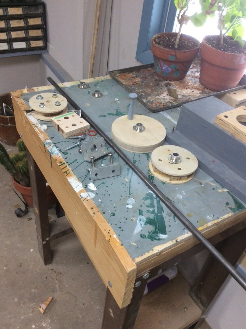
the disc disc in the foreground is a rachet, a precaution to prevent the machine from eject the sled into the operator. To back up the sled the pawl (not made yet) is disengaged.
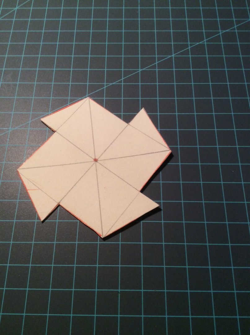
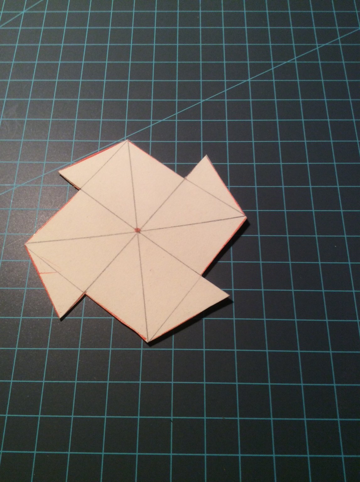
The cardboard pattern for the ratchet.
- bruce d, Canute and Keith Black
-
3
-
I second Bobs recommendation for Ansel’s book. I also recommend “To Build a Whaleboat” by Eric Ronnberg, and “Whaleships and Whaling” by Albert Church.
Church’s book is especially interesting as he either furnished cameras to whaling crews, sailed himself, or both; I don’t remember which. The result is a remarkable series of photos detailing the entire whaling process. The pictures show whaling under sail during its final days.
Ronnberg’s book describes whaleboats from an earlier period, mid Nineteenth Century. It includes both history and construction of the Model Shipways kit. If buying the kit, see if it is included. Ronnberg’s book includes many details not covered by Church or Ansel. He has spent a lifetime researching the New England fishing and whaling industries.
Roger
-
I have a bottle of “Blacken it”. If I take reasonable precautions- file surfaces to bright metal, a short soak in a small tin of acetone or lacquer thinner, then immersion in the blacking solution I have never had it fail to work. It will not blacken solder so I touch up those areas with a dab of flat black model enamel. To prevent later damage to the blackened surface I seal it with a spray of Dulcote.


Improving a Homemade Thickness Sander
in Modeling tools and Workshop Equipment
Posted · Edited by Roger Pellett
In the event of a kickback, the ratchet rotates backwards, counterclockwise and the pawl engages the teeth stopping movement. The pawl is pinned at the top, so is in compression only; no shear or bending. There is a spring that keeps the pawl in contact with the ratchet teeth.
To retract the sled, the machine is turned off, the pawl is rotated by hand counterclockwise to disengage, and the sled is pushed back by hand.