


Chuck
-
Posts
9,724 -
Joined
-
Last visited
Content Type
Profiles
Forums
Gallery
Events
Everything posted by Chuck
-
 Beautiful work. You are making some fantastic progress. Well done!!!
 -
New 1:48 scale POF kit of the Cutter Alert from Trident Models in China
Chuck replied to MSW's topic in Wood ship model kits
They dont have a website to my knowledge and usually sell through EBAY and Amazon.....as well as some other similar sites. They dont have any available at the moment but should have some soon. -
Thank you..... I try my best to make some great quality rope!!! Its easy to make once you get the feel for it. I encourage everyone to try it as well.
-
Yes that nylon stuff is brutal. chuck
-
Justin.....I am actually cutting more Medway longboat kits this week. I am already about half way done with another six kits. So sooner than later..... Chuck
- 66 replies
-
- 1
-

-
- Finished
- Model Shipways
- (and 1 more)
-
No as I cant open up ordering on my site for one person internationally. I will email you. Chuck
-
It looks really great actually. I wouldnt worry about the lower counter. That looks really good. The curve of the upper counter can be adjusted visually by slightly tweaking your molding so the upper counter is consistent in width and the curve on top and bottom is the same.....or at least closer to being the same. So dont worry about that too much. You need to buy chapter 3 of the project in Cherry? Of that is all you need to buy at the moment I may use you as a test to see how the international mail is running. If you want to give it a go....send me a PM so we can discuss the details.. Chuck
-
They have some nice pieces. Very expensive however. I wonder if the ship to the usa?
-
Looking good so far!!!! Take your time with those qgalleries. They are tricky buggers.
- 642 replies
-
- 3
-
-
- winchelsea
- Syren Ship Model Company
- (and 1 more)
-
really nice work.....I am glad you enjoyed the project. You did an exceptional job on it!!!
- 46 replies
-
- 3
-
-
- medway longboat
- Syren Ship Model Company
- (and 1 more)
-
Great to see your build log Shawn. We have all been there with those bulkhead extensions. Its usually an easy fix thankfully. Looking forward to seeing more and refreshing to see another cherry version being made. Chuck
-
ancre Coureur by cafmodel - 1/48
Chuck replied to cafmodel's topic in - Build logs for subjects built 1751 - 1800
Beautiful work Tom!!! -
Posting kit instructions?
Chuck replied to Gaffrig's topic in Using the MSW forum - **NO MODELING CONTENT IN THIS SUB-FORUM**
I just looked and the other ship in bottle instructions are there but unfortunately not for this particular kit. So yes by PM only please. -
Posting kit instructions?
Chuck replied to Gaffrig's topic in Using the MSW forum - **NO MODELING CONTENT IN THIS SUB-FORUM**
No I dont think so.....Amati is still around. I am sure they have it on their website. Chuck -
Looks great Mike. That is coming along wonderfully.
- 607 replies
-
- 2
-
-
- winchelsea
- Syren Ship Model Company
- (and 1 more)
-
Well done. But just as an FYI, that molding across the transom, it really shouldnt be there. That was never a detail on these small boats. In fact.....take a look, the rudder cant actually move now. And internally strapped blocks....probably not used. Just a stropped block with a thimble. But you did a fine jon making them. Chuck
- 87 replies
-
- 1
-
-
- Model Shipways
- 18th Century Armed Longboat
- (and 1 more)
-
ancre Coureur by cafmodel - 1/48
Chuck replied to cafmodel's topic in - Build logs for subjects built 1751 - 1800
Tom that is looking really good. Nice touch on the triangular eyebolts. -
I am sure you can make another. Rich that looks pretty darn good. Those came out great. I know how tiny they are and that makes it even more impressive.
- 109 replies
-
- 1
-
-
- model shipways
- kate cory
- (and 1 more)
-
Its always open.......still time to jump in.
- 1,784 replies
-
- 2
-
-
- winchelsea
- Syren Ship Model Company
- (and 1 more)
-
That looks excellent. It must feel good to be making sawdust again.
-
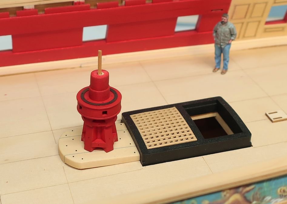
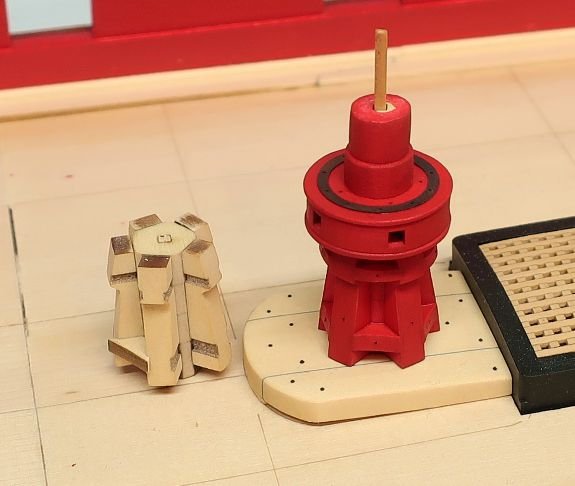
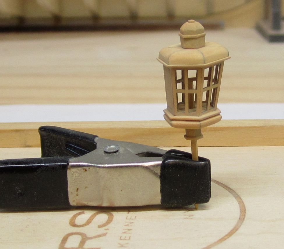
Capstan experiment one. I got bored and burnt out making inventory items. So I decided to test out my parts for making the lower capstan. I have had the parts laser cut for a while. I didnt take any construction photos as this was just a test but keep in mind this is way before we will actually need it. I am always just a little ahead with the design stuff. So I will make another and document each step. I want to make the center spindle a bit heavier that goes between decks above the capstan drum. So I will tweak that before I make a new one. But what I wanted to show you guys is how I did it. I tried a new design for fitting the chocks into the whelps. Below you can see my very first proof of concept testing to see if I could laser etch notches on both sides of the whelps. It worked beautifully. So all you need to do is slide the chocks in after test their fit. This was a challenge even at this scale because these parts are still pretty tiny. The other parts including the capstan drum are all built as usual in layers on a 1/16" x 1/16" stick to register them. Very similar to the way I designed the stern lantern mini-kit for the winnie. This was a fun mini kit to build and will look great painted or left natural. I will detail its construction in Chapter 5.....sorry to jump the gun. I couldnt help myself. These will be made available as stand alone mini kits in 1/4" scale and 3/16" scale as well.
- 1,784 replies
-
- 26
-
-

-
- winchelsea
- Syren Ship Model Company
- (and 1 more)
-
Cant see why it wouldnt work. Although I prefer to start at the top of the wales. This way, if I screw up and have to shift some of the lower planks it wont be as noticeable.