DONATION DRIVE - SUPPORT MSW - DO YOUR PART TO KEEP THIS GREAT FORUM GOING!
×


Chuck
-
Posts
9,693 -
Joined
-
Last visited
Content Type
Profiles
Forums
Gallery
Events
Everything posted by Chuck
-
 I have already sprayed them so you are good to go. BUT you may want to lightly spray again if want. Use a matte spray fixative is best. Hairspray is a last resort.
- 221 replies
-
- 2
-

-
- queen anne barge
- Syren Ship Model Company
- (and 1 more)
-
That is turning out terrific. Nice job with the painting. You are gettin close now.
- 221 replies
-
- 1
-
-
- queen anne barge
- Syren Ship Model Company
- (and 1 more)
-
Its all a learning process. If you can get through planking this hull I am sure your next project will be even better.
-
You mean the etched lines and letters. That is done by running the laser at very low power and a higher speed. The laser doesnt cut all the way through. It just lightly scores the surface and it shows up because it burns a Light line in the wood
- 1,784 replies
-
- 2
-
-
- winchelsea
- Syren Ship Model Company
- (and 1 more)
-
Its really coming together Glenn. Looks really good so far.
- 778 replies
-
- 3
-
-
- cheerful
- Syren Ship Model Company
- (and 1 more)
-
Yes...very nice. Its looking vey good
-
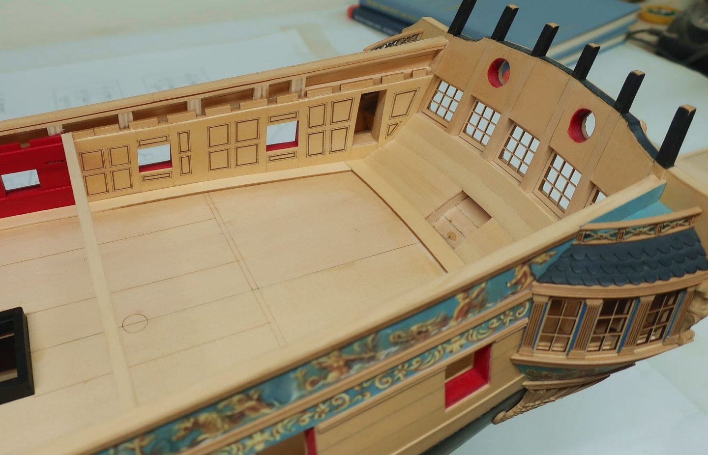
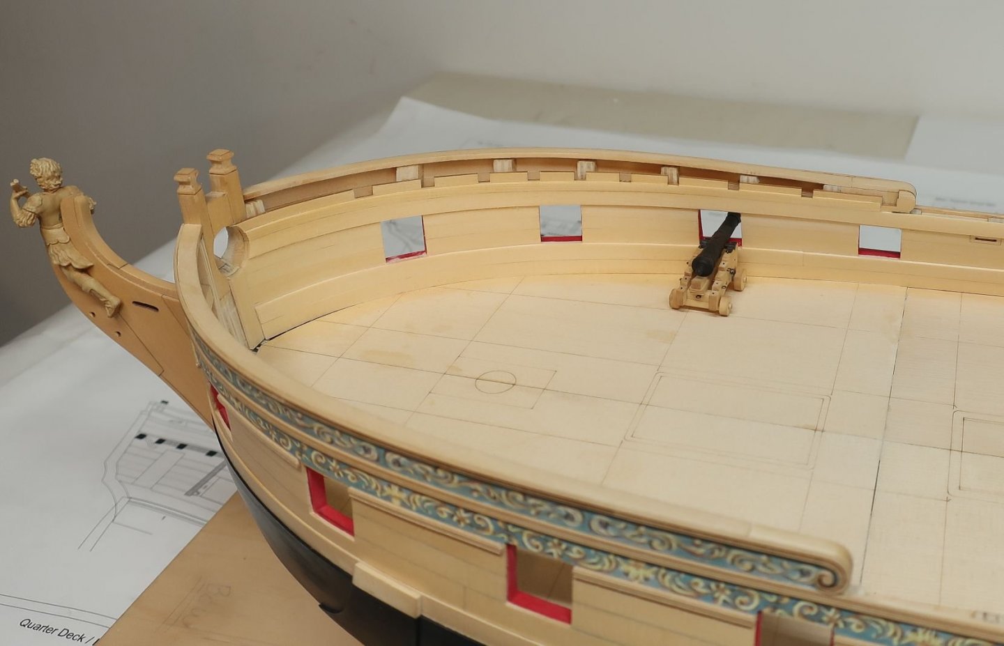
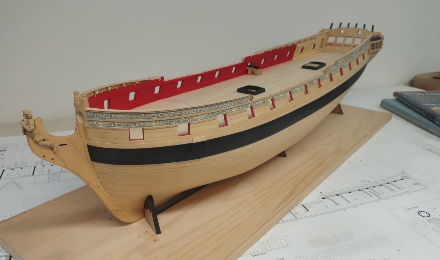
Today I planked the inboard stern. There are five strakes. They are all laser cut with the proper curve. Note that I started with the top plank so it would be flush with the bottoms of the windows. We will be adding a thin sill and some molding later on top of this to finish it off. Excuse the dust!!! But each new addition does clean every up a bit and make it look nicer covering up all of the frames and bulkheads. I also decided NOT to high light the seams between these planks as I think they would look too busy. It will look cleaner this way with the paneled rudder trunk and benches in front of it. Also not how the bottom three planks dont span the entire width of the stern. The center will be left open for the rudder and this whole area will be covered with the paneled rudder trunk. In fact we will be adding the rudder real soon. But first I want to get the deck planked. So next up was adding the margin planks. These are also laser cut with scarfs. But be aware that it is unlikely that these will fit your model perfectly. There will be so many differences in the way each of you fair inboard and create the inboard shape of the hull. So some of you will no doubt have to use them as a starting point to trace them and cut new ones to fit your model. Its not very hard to do. They are 3/64" thick. The aft section against the transom was positioned first. The aft edge was beveled to fit snug against the transom. Then I started adding each of the four sections along each side. Starting at the bow and working my way aft. Next up I will add the waterway which will be a 1/16" x 1/16" strip that is angled on the inboard side. You know the drill. Its the same way as done with all of my projects. Once that is done I will start building the platforms and coaming down the center of the deck so I can plank around them. Here is how she looks now. Testing the deck beams too!!!

- 1,784 replies
-
- 39
-
-

-
- winchelsea
- Syren Ship Model Company
- (and 1 more)
-
Dont get ahead of yourself. I will be making the ships boats too. But prob a pinnace. It looks better. But thats down the road. They will be stored on spare topmasts in the waist.
-
They are just spares....I had extra room on the sheets so I figured why not add some. It is looking very good.
-
No but keep in mind that the contemporary model doesnt match the original draft in many cases. So I went with the original draft for my measurements. In the end it wont matter. It will just look a bit different. You could actually go with either way depending on what you like best.
- 1,784 replies
-
- 1
-
-
- winchelsea
- Syren Ship Model Company
- (and 1 more)
-
HMS Winchelsea (1764) 32 gun frigate GROUP PROJECT INFO
Chuck replied to Chuck's topic in Group Projects on Model Ship World
You guys should try.....to get started with little investment I recommend cutting your bulkheads by hand. If you could complete chapter one without too much trouble then you can absolutely build it. Its no more difficult then building and planking any frigate kit. Its just that this time you will be learning how to plank properly as opposed to the "creative" methods suggested by most kits. AND although most who do a good job planking the lower hull will want to leave it so folks can see it, the Winnie was copper plated and that would be a an option if its the planking that scares you. -
That looks so much better. So well worth the effort. Well done.
-
That looks good. Best to have all laser reference on the bheads facing forward for the lettered bheads. Its the opposite for the numbered bheads.
- 778 replies
-
- 2
-
-
- cheerful
- Syren Ship Model Company
- (and 1 more)
-
The kit is indeed pirated. The plans were stolen from an author who produced them for a ship model magazine in the 1990's. The plans were stolen from the author without permission. No legitimate kit exists from the plans BUT....it is a relatively easy subject to build. The plans are available for sale in copies of the magazine you can find online. I own a set of these plans and they are so easy to use to scratch build it with some simple tools. They were drawn by Peter Danks for Model Boats magazine in 1993. It was the March issue. Much like Model Shipwright magazine, this magazine routinely printed and inclused full sized plans in many issues. These are easy pickins for slimey pirates. Many of the kits these companies pirate are based on such plans froms the 70's, 80's and 90's. I might also add that I have received official permission to use these plans to create a kit in the future if I choose to. Its such an easy and attractive project I might just do that. Although I would use my design for the skeletal and frame parts. Its a little dated. It is a model of a water Hoy.....You should build it from scratch!!!! Chuck
-
Ken that looks really good. A really nicely planked hull!!!
- 238 replies
-
- 3
-
-
- sloop
- providence
- (and 1 more)
-
Remember...Cheerful isnt an all-in-the box kit like the longboat or barge. More scratch parts etc. Not a kit at all. It is a semi scratch project with some fittings and parts lasercut. I really do wish more would try scratch building some of those fittings as well. Everything you need is listed on the website including a list of rope and blocks. But you may need a few odd pieces of wood for some stuff not seen like the false deck and rabbet strip. You can simply buy basswood for this other stuff. Chuck
- 778 replies
-
- 7
-
-
- cheerful
- Syren Ship Model Company
- (and 1 more)
-
Looking good so far. Just remember to keep you nails cut short and keep your hands clean while using the cedar. Once you get used to it, its a wonderful wood to use.. Chuck
- 778 replies
-
- 8
-
-
- cheerful
- Syren Ship Model Company
- (and 1 more)
-
Im going to leave the panels natural. Just some poly. But as I mentioned in the instructions...a shade very close to the contemporary model can be achieved by using Old masters fruitwood gel stain. No masts or rigging sorry. But those can be added on your own if you like. Its pretty standard stuff. My hull will end up this same color when done. Its what I prefer. But you can use whatever finish you prefer if you build her. I should have my store back open next week sometime. It depends on whether or not the post office has gotten their act together. I may send a few test orders out just to be sure before opening up.
- 1,784 replies
-
- 7
-
-
- winchelsea
- Syren Ship Model Company
- (and 1 more)
-
Yes the ports around the panels were touched up before the panelled sheets we glued in place. As far as the other planks....no I waited to trim back those planks and then apply wood filler if need. Then those gun ports were cleaned up and painted at the same time as the inboard bulwarks. Chuck
- 1,784 replies
-
- 3
-
-
- winchelsea
- Syren Ship Model Company
- (and 1 more)
-
That looks good. No i did t mess with those. Its the same as on my model.
-
ancre Coureur by cafmodel - 1/48
Chuck replied to cafmodel's topic in - Build logs for subjects built 1751 - 1800
Beautiful work Tom!!! You have been busy. -
Thanks Jeff Its the usual Grumbacher Crimson acrylic paint from a tube. I have a lot of clean up to do and many more coats before its all finished.
- 1,784 replies
-
- 5
-
-
- winchelsea
- Syren Ship Model Company
- (and 1 more)
-
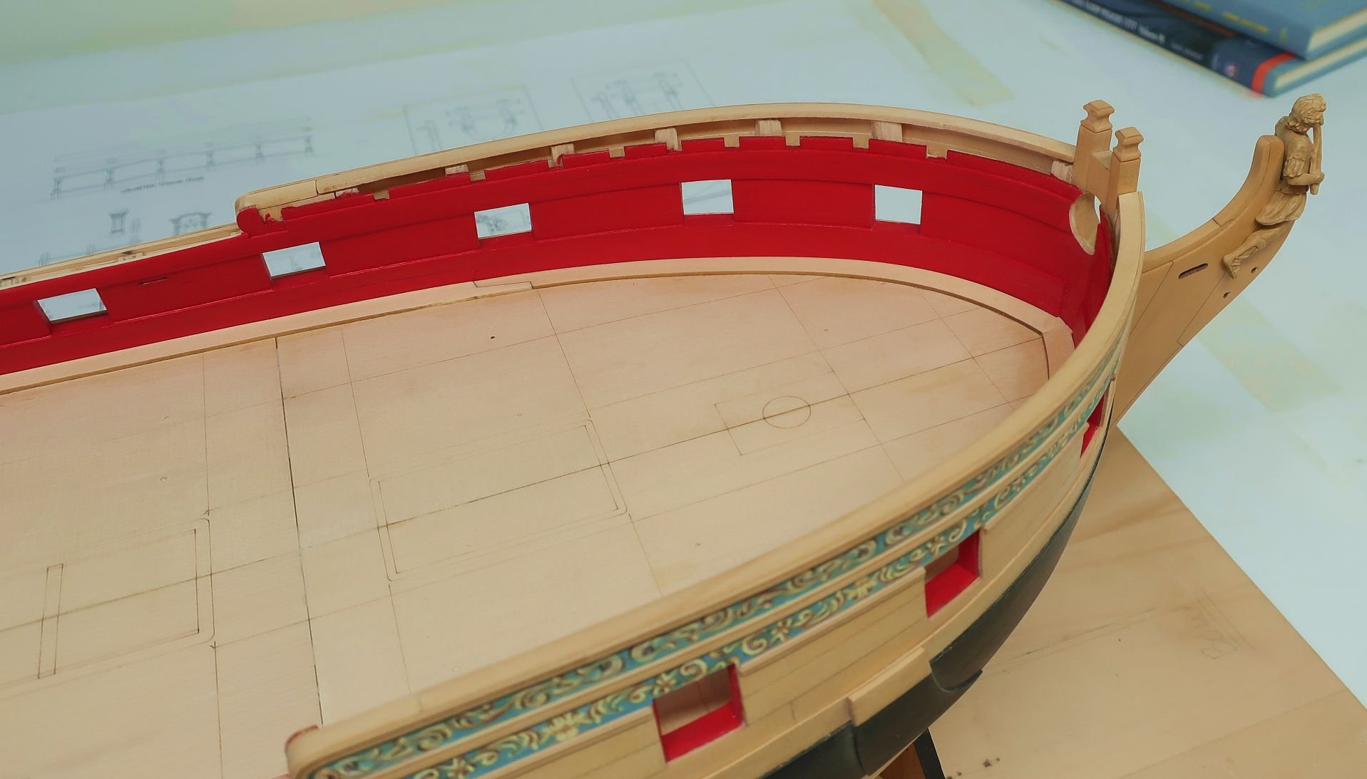
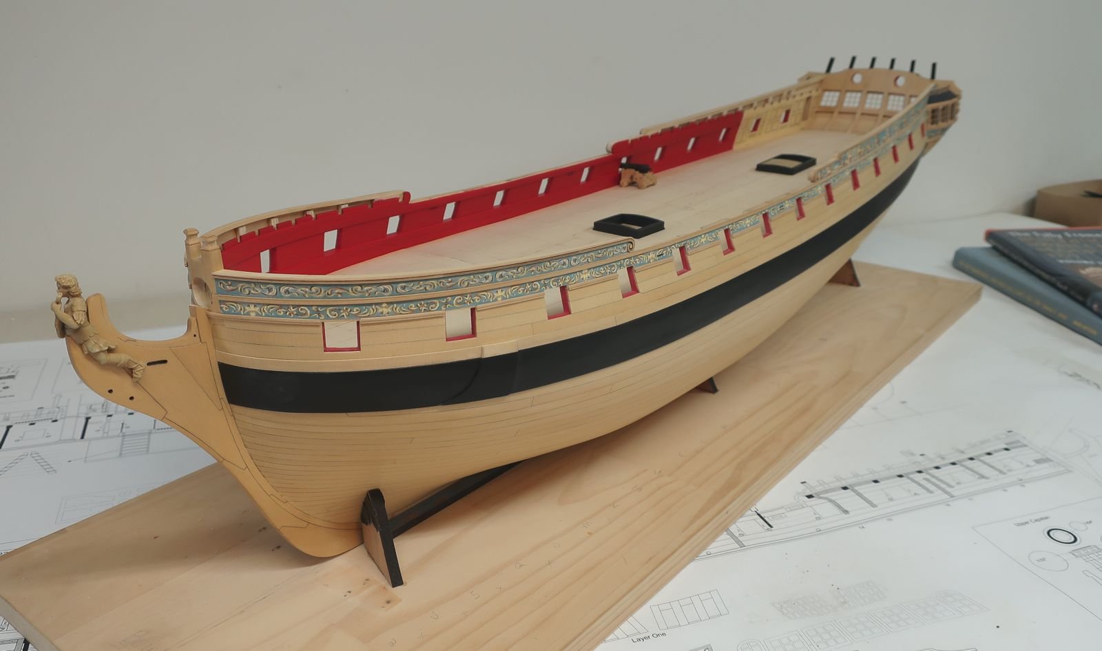
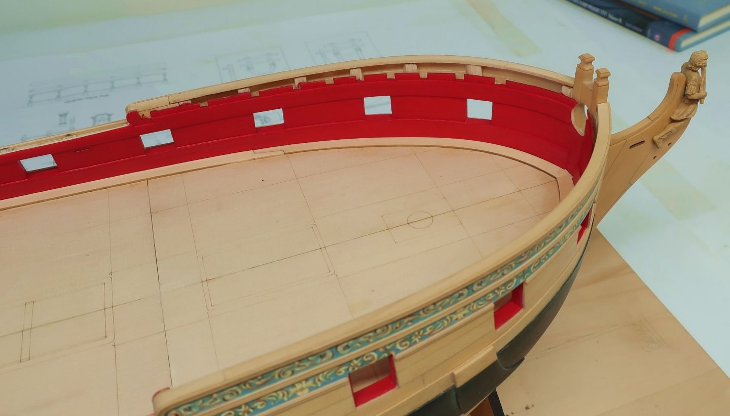
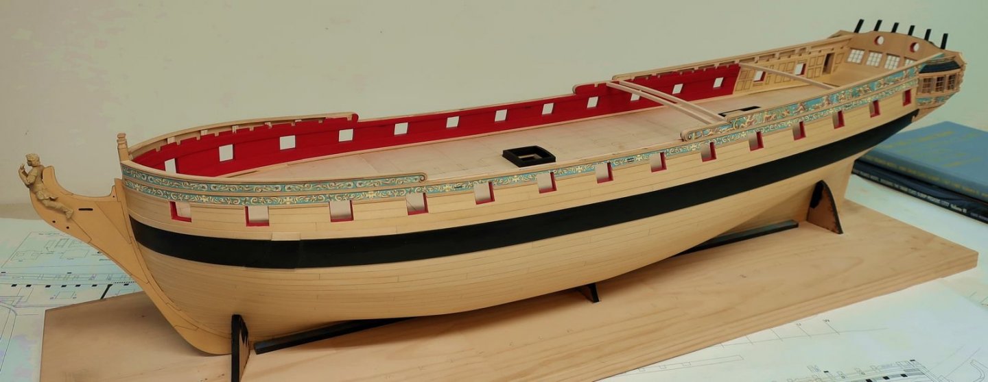
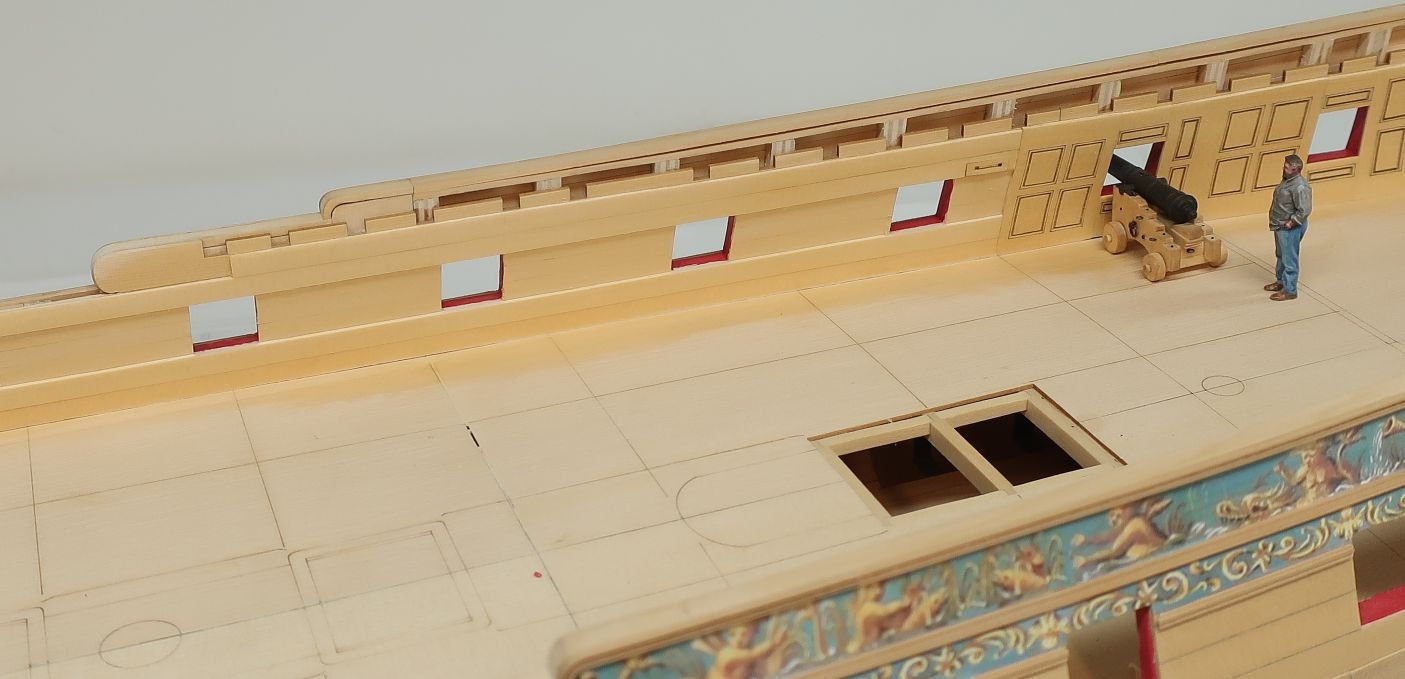
Next up it was time to add the second layer of spirketting (the lower two strakes) and the 7/32" wide plank above the ports. I used planks that were the same width but just 1/32" thick. You can even sand them thinner if you like. I also added the aft shell for fixed block. See it forward of the panelling? This should be added at this stage so you can plank the second layer around it. Note how I also added one more 1/32" second layer strake above that 7/32" wide strip. The top edge follows along the bottom of the notches in the deck clamp. I use various width strips because you will need to taper it. It is not a consistent width. Just make sure the top edge is flush with the bottom of the notches in the deck clamp. MOST important....look at the forward end of this additional trip. Notice where it starts in relationship to the first notch in the deck clamp. This is important because it will aid you later when we build the platforms for the gangways. Here is a view of the bow area. Same things apply. Notice where the aft end of the plank ends in this instance. Once again it is even with that first notch. Sand everything smooth and prep the bulwarks for painting. Then paint it red. But dont paint the fancy panels aft. Here is what my model looks like at this stage. I still have to complete the port side....havent started planking that yet.
- 1,784 replies
-
- 35
-
-
- winchelsea
- Syren Ship Model Company
- (and 1 more)
-
That is the science museum model of the 74 gun Warrior. Also note the deck beams painted red on each side. I may be doing this on our model. Its a very common feature although in some cases just the knees are painted red.
- 1,784 replies
-
- 1
-
-
- winchelsea
- Syren Ship Model Company
- (and 1 more)