HOLIDAY DONATION DRIVE - SUPPORT MSW - DO YOUR PART TO KEEP THIS GREAT FORUM GOING! (Only 68 donations so far out of 49,000 members - Can we at least get 100? C'mon guys!)
×


michael mott
-
Posts
5,200 -
Joined
-
Last visited
Content Type
Profiles
Forums
Gallery
Events
Everything posted by michael mott
-
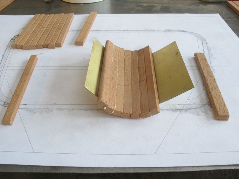
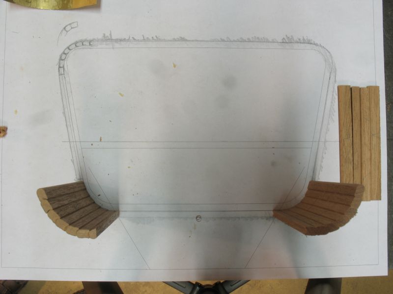
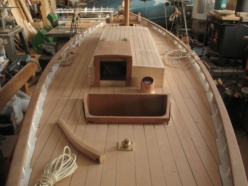
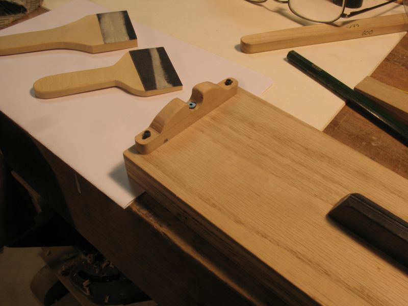
 New Cockpit Part 2 The second cutter was not quite a successful as the first so a bit of handwork was needed to clean up the round, Basically I made it a bit too small. I shaped a piece of .008" shim-stock to the aft curves on the deck hole to act a a platform to lay the boards while they set. After they set one edge was trimmed on the disk sander . This method is working well enough so on to the forward curves. Michael
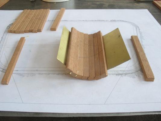

-
The juxtaposition of the superbly clean model and the workspace was amazing! I work in a similar manner. Michael
-
Bob my chair is right next to Elia Michael
-
Low speed power drill
michael mott replied to grsjax's topic in Modeling tools and Workshop Equipment
I just started to salvage an old broken Dremel 750 minimite cordless after seeing the fine pencil like drill Ed Tosti was using. Getting the chuck off the motor was a devil , however they assembled it it was powerful enough to pull the spindle out of the armature windings on the little 4.5 volt motor. Then I added a flywheel and will fix it to a 12 volt Sagami can motor from the world of model railroads. I will use the telescoping brass tubes to form the body. The motor does not have a lot of power but with the brass flywheel it will have enough torque for small drills. I got the idea from Gerald Wingrove a few years ago he used a small model locomotive motor for a mini drill. Michael
-
Budget Lathes in UK; Advice please!
michael mott replied to Phoenix_63's topic in Modeling tools and Workshop Equipment
Looks like a very nice lathe, 20mm spindle bore is better than my Myford ML7. Michael -
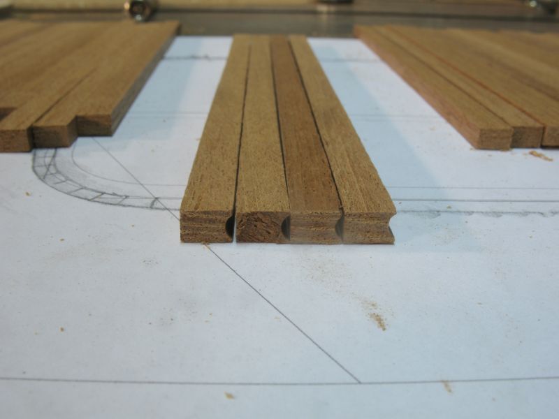
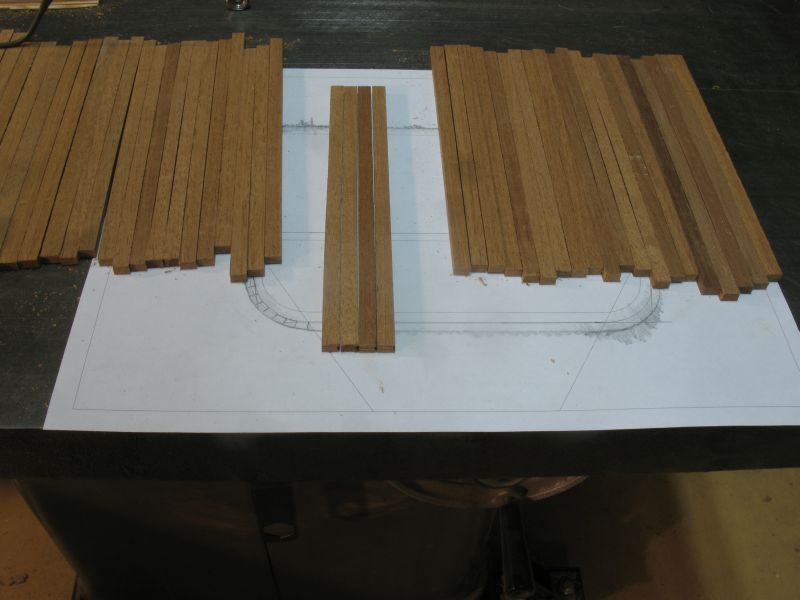
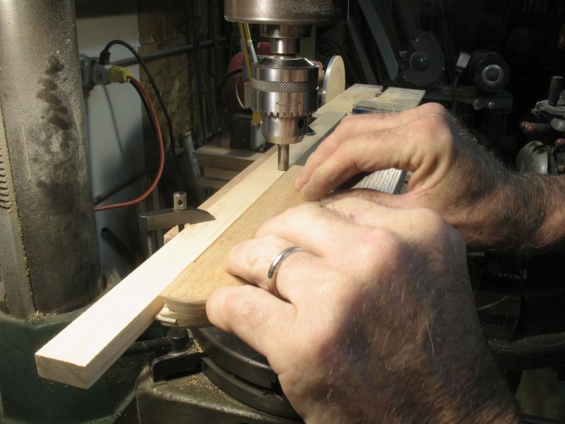
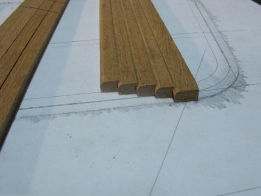
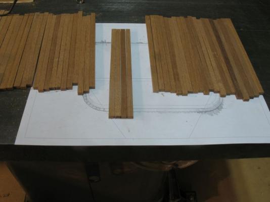
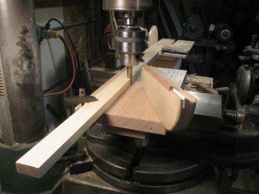
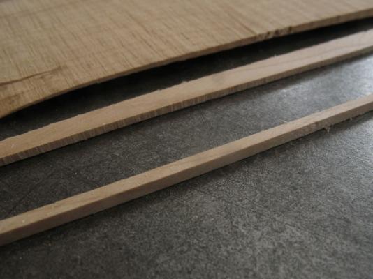
New Cockpit part 1 I have begun building the new cockpit, the first task is to prepare the mahogany boards that will form the walls of it.I have chosen 1 1/4 inch as the thickness of the boards and the widths will vary slightly from the corners and the straight sections. The first picture shows the new boards rough cut to double the length of the depth of the cockpit over the tracing of the opening in the deck. The second picture shows the first shaping of the corner boards these will be similar to the edge planking that some cedar canoes are made with a matching convex and concave edge to wrap around the curve. I turned a convex shape on the end of some 3/8 drill rod then rough ground the cutter edges I made it a four flute then hardened and tempered it, honed the edges with a carbide stone in the Dremel tool. The set up was done with the mill, in order to push the board I used the push board from the table saw by cutting a slot in the push board that was the same set up as the thickness of the boards I slipped a strip of 1/16th styrene into the slot and added a strip of 10 thou sheet to make it tight. This allowed me to add good even pressure and keep my fingers away from the cutter and the best thing was only having to make one pass. I will cut enough for all the corners then make a corresponding cutter for the convex side of the corner boards. I will tongue and groove the straight boards Michael


-
Yambo thank you for your thoughts, it prompted me to ask a question in this thread. Daniel thank you very much for your very informative reply to the cockpit coaming issue, as a general designer I sometimes wonder why a design that looks good in some respects nudges my intuition with "Something isn't right though thought" As I have been working through the various elements on this model I end up taking a break to get a long view of what is needed and why. this Cutter model is and has been very important to my own learning with regard to ships and boats in general. I am beginning to be able to see some things of nautical design that I would have missed earlier but now I understand, I think that this is why I am not reticent to change or redo something on this model, because it is also about the journey for me and not the destination. Hopefully I will end up with something I am pleased with overall. Michael
-
Yambo I am looking at these examples of various cockpits. When I started building this model I knew a lot less than I do now and I still don't know very much about these boats but I am learning. My next model cutter will be of an actual cutter which will make some aspects a lot easier no doubt. As for this build it is a mixture of aesthetics and my own knowledge of sailing full size sailboats that are helping to guide my decisions, alongside examples of new and existing pilot cutters. If that makes any sense then you are less confused than I am. http://www.sandemanyachtcompany.co.uk/uploads/439/Birdseyeview.jpg http://images1.hellotrade.com/data2/NJ/CD/HELLOTD-1823938/HesperAlongs_500x500.jpg http://www.pilotcutter.co.uk/sites/default/files/stern.jpg http://newimages.yachtworld.com/resize/1/63/80/4476380_20131210043953740_1_XLARGE.jpg?f=/1/63/80/4476380_20131210043953740_1_XLARGE.jpg&w=606&h=467&t=1386679453000 http://mahasagarboats.com/pilotcutter/images/92pict07.jpg Michael
-
Tom, I would guess from all the cockpits that I have looked at that there seems to be no hard and fast rule for this dimension. Michael
-
Sailor, thanks for your thoughts Tom, in a word NO, I don't do heights. I see what you mean John I will mock it up first now anyway I will need to make it a little larger all around in any case. Michael
-
She is really taking shape now, I am enjoying watching this come together. Michael
-
Great to see you have finished this fine model and now .... the Howard? Michael
-
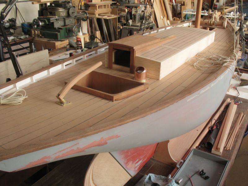
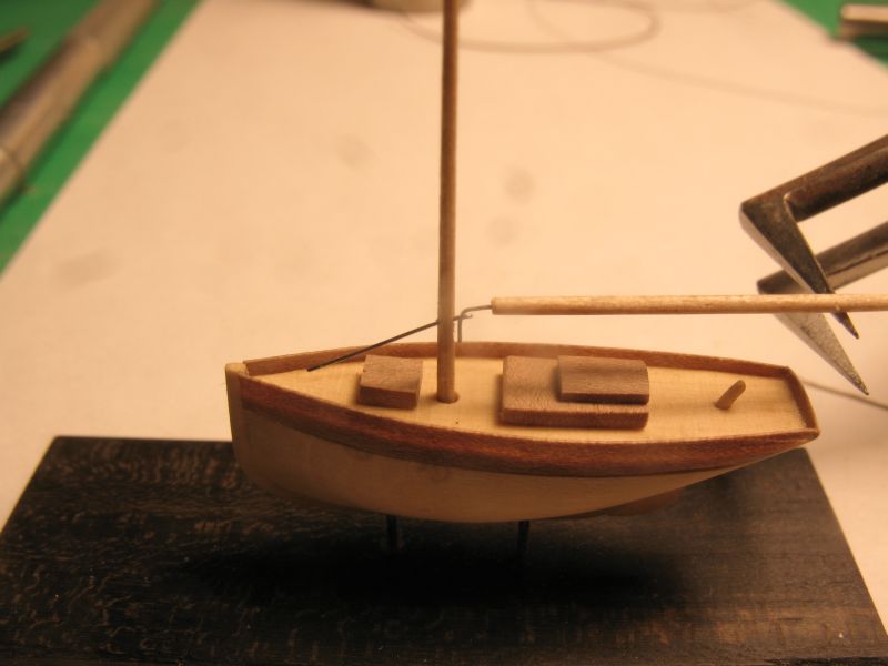
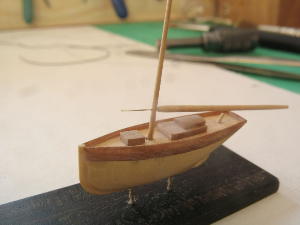
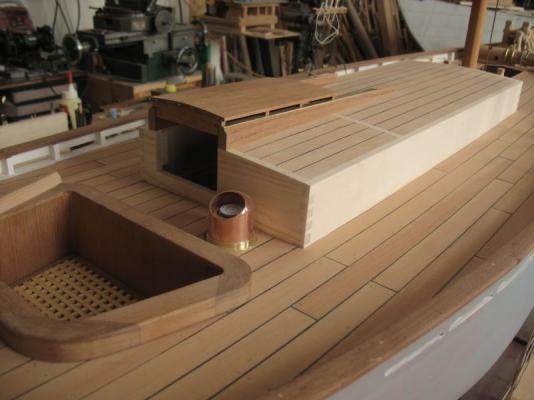
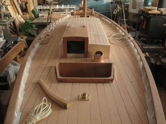
Tim, John, Sailor, Denis, Greg, bob, and Tom, thanks for your feed back on the change. and for the likes. Regarding a place to sit I was thinking that something along the lines of this cockpit on Mascotte would be good. I notice that Olga alongside has a similar set up. There is a seat across the aft end of it and for standing the walls are a little higher which I would think will support one a little better with the slightly higher walls and better for keeping water out. My original thinking was to have a gasket under the edge of the top of the cockpit so that I could seal it. I am now thinking that if i rebuild it the same basic style as the one on Mascotte then I can fix it solidly to the hull with a lift out bottom to access the lines to the rudder control. But I can fit a clear lid into the top when I put it into the water. The picture that shows the reshaped cockpit that I have already made shows the fact that it was a loose fit into the hull. This change will allow me to use narrower planks and fit to the curves in the deck better with a caulked seam around the joint between the cockpit and the deck which would also look better I think. Michael
-
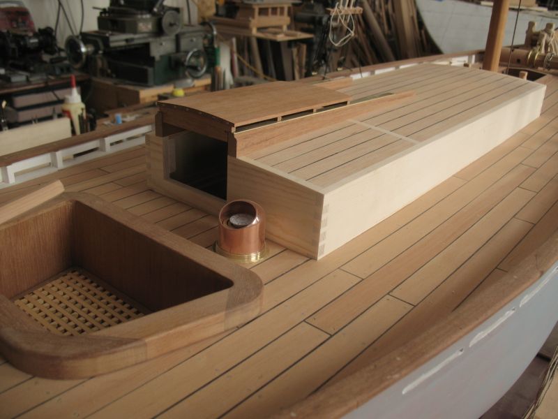
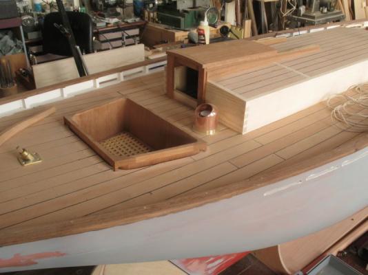
First I would like to thank you all for your kind remarks and all the likes, I can see the merit of the likes button these days and have started to use it myself. Well working tiny has its limits and so I am back on the bigger cutter for now. As I have been working on the cabin structure the mahogany surround of the cockpit has been troubling me I kept looking at the wide surface and the large diagonal sweeps of the corners and it kept nagging me. In order to resolve this issue I just gave it a bit of a trim. I think the narrower look is much better. I think this will mean building a new cockpit with a more narrow wall that sticks above the deck about 8 inches in scale. I am beginning the trim for the closure of the companionway. Working through the pros and cons of doors or boards. Michael

-
I have one that I never used much, the belt wandered a bit and they were expensive mine was a pedestal model a craftsman. I cannot remember how I came by it even The disc sander is ok, however I did not like the way the table was mounted (basically a shaft sticking out of the cast base. I prefer a more solid table. I used it for rough work when I did used it. The drums at each end of the belt part are slightly barreled in shape to keep the belt centered. I converted mine to a pedestal table that has a bench grinder and at one end and a wire wheel and buffing wheel at the other I took off the disc. Not a very positive recommendation for sure, but they are useful for some applications I would not recommend it for modelmaking though, it is a bit of a brute. This is of course just my opinion, I am sure there are those who use them all the time for general woodwork. Michael

-
Antony, your skill is evident with the fact that you can hold up that deck and it is just good joints that are holding it together. Beautiful workmanship. Michael
-
They look very sharp. I am curious as to the reason that they exist, is it simply to deal with the knees coming from opposite ends and this is where they meet? Michael
-
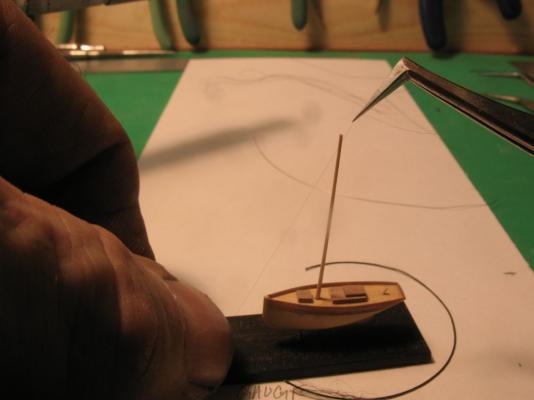
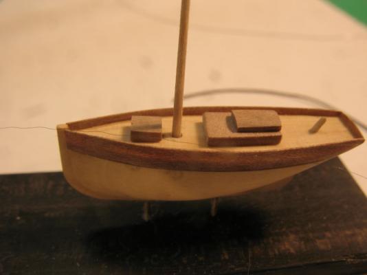
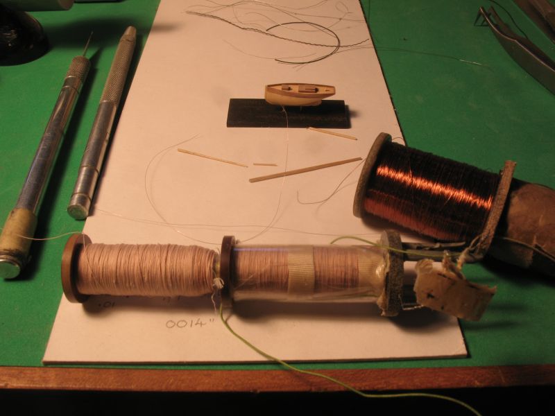
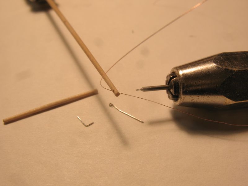
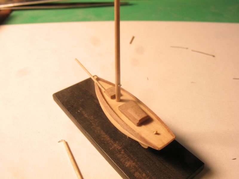
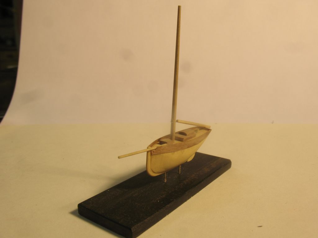
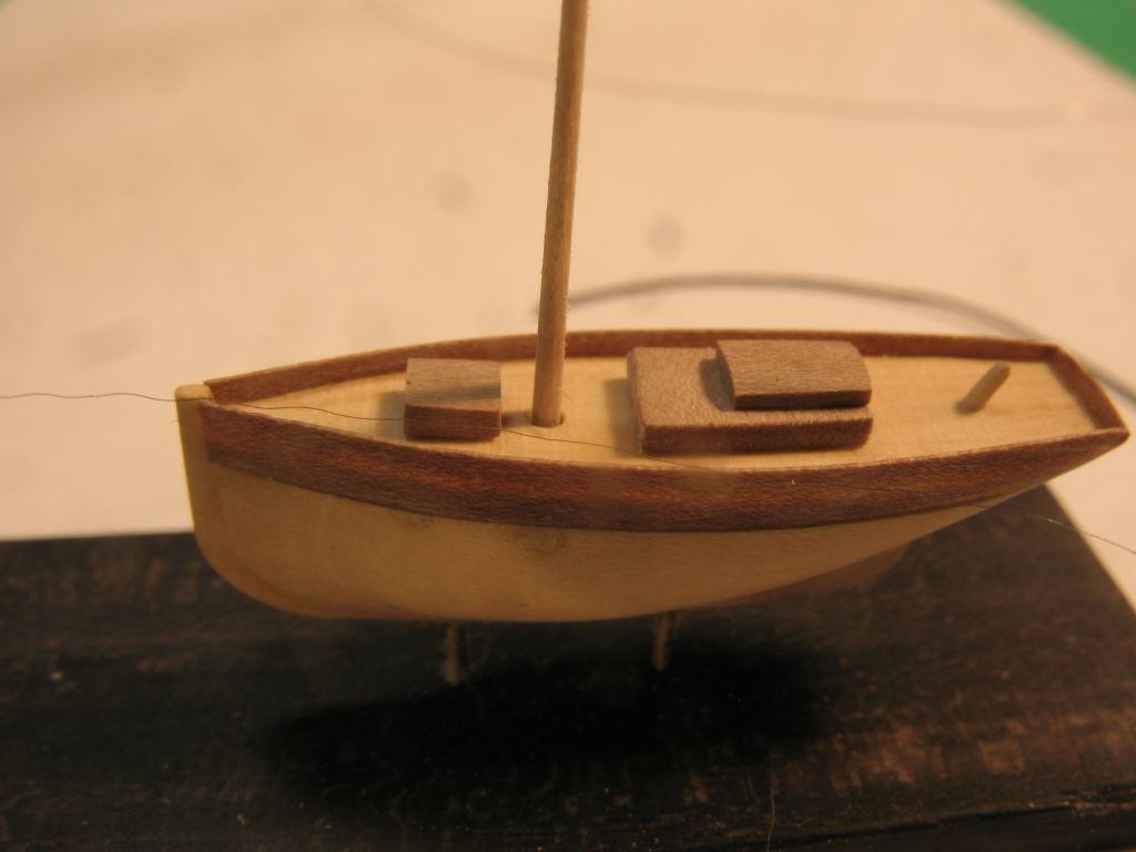
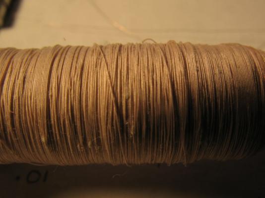
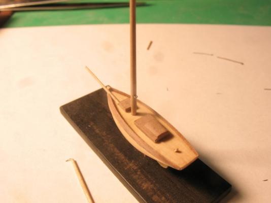
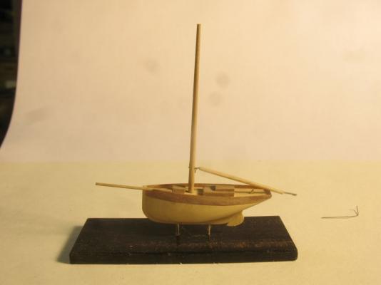
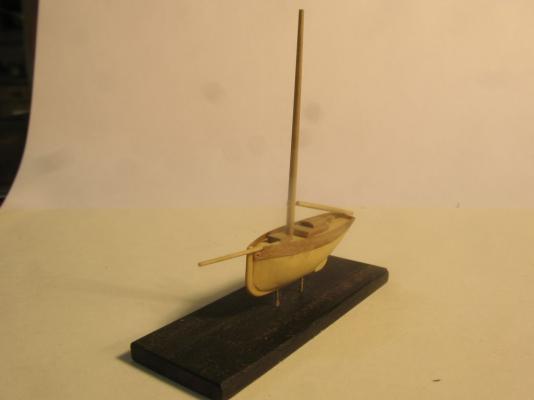
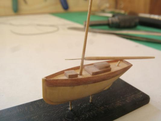
Dave, thanks for the tip regarding the hoop and pegs. Bob, I am pleased that you are following along. I did look at the windings on a couple of very small motors today both were a larger Diameter than the telephone coil wire, which is .0028" Early this morning while reaching for a piece of wire I caught the top of the mast and snapped about 1/4 inch off, so I had to make a new mast. I decided to use some of the Lilac so stripped off a 1/16 x 1/16th square of it, then filed it round in the new mini dowel filing jig. next is a shot of the telephone coils And a close up of the wire with the thread coating. I needed to make a modification to the filing jig so that I could also use it as a drilling jig, to that end I added an adjustable saddle for the pin vice with an elevating screw to counteract the taper on the mast or other spars. there is also a second V groove for the initial shaping. for the shaping of the mast I made a couple of paddle sanding sticks so that the taper was even they are 400 and 600 Drilling the .008' holes was a bit nerve wracking, I pushed the mast down onto the v groove which stopped it from rotating while I drilled the hole with a watchmaking pivot drill in another pin vice. the next picture shows the .0028 wire through the hole at the top of the new mast the diameter at the top is .030 which is a bit heavy but looks OK. the next picture shows filing down the shoulder on the mast to fit the hole in the deck. I really like the way this new jig works. The next **** shows the goosneck fixed into the mast the wire is 36 gauge wrapped around some .011 hard wire then closed up a little more with a couple of pairs of pliers. the next two show the current state of the build, with the old mast being salvaged and being used as the bowsprit. I am going to take a break from the micro it is hard on my nerves, and get back to the Bristol cutter for a bit. Michael


-
Pete this build is getting really interesting, I am enjoying your developments, I am also looking forward to the planking. Michael
- 153 replies
-
- 1
-

-
- musongus bay
- sloop
- (and 1 more)
-
Druxey thanks for that I will check what I have tomorrow, I do have a bunch of old telephone switching coils, That i remember having some very fine wire. Mark thanks for the usb and ear bud ideas I did have an old set of buds and just measured the wire in them and the strands are 39gauge or. 00351inches, which translates to 1.75 inches, did check fly tying wire and the ultra fine Nano wire is .1mm or .003937inches. I looked at the wire on one of the old telephone coils and it is .0028" which is 41 gauge, I think that this might be just the ticket. I will see what I can do with it in the morning. it works out to 1.4 inches in scale which is still large by real life standards for a boat this size. I will see what I have in the way of small transformers and even the coil in a cheap quartz clock mechanism might be thin enough. I did find this source for fine wire which tells me that it is available Michael
-
Thanks John. I think with a little bit more fiddling I can get this goosneck looking reasonable. definitely need a visor. michael

-
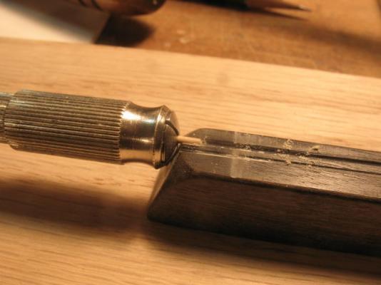
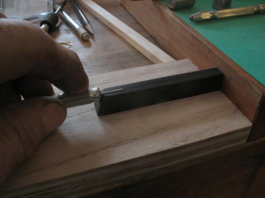
Bob, it is funny you should mention that, I was wondering about the amazing work of some of our companions on the wonderful journey through life as I was working out how to get really small threads. John I just found some 36 gauge copper wire and it looks pretty fine, I am wondering if there is a smaller diameter wire easily available. it would definitely be easier. Druxey, thank you very much. Today I sorted out a new filing jig for working with very small diameters, taking a cue from the world of watchmaking I made a small guide to rest the dowel in and using a sanding stick with 600 grit am able to easily work on the wood. some of course will recognize the salvaged black key. lovely ebony that no doubt was part of some wonderful music in its earlier life. twirling the boom in the pin vice at the same time as using the sanding stick. A fair way to go yet, drilling the hole in the mast was a bit fiddly I really must get one of those magnifying lights or a good visor. the pin in the end of the boom is some 38 gauge hard wire basically .004" I am thinking that I need a better mast and then I can bend the wire in the end of the boom and drop it into a goosneck formed from a couple of wraps of wire on the mast. That's it for now. Michael

-
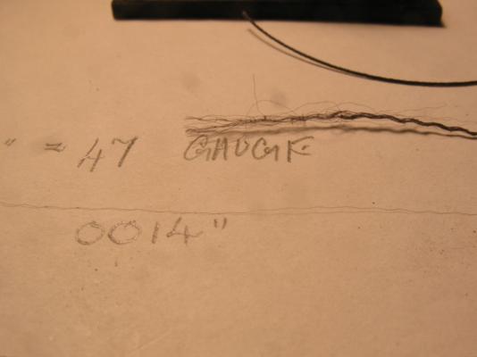
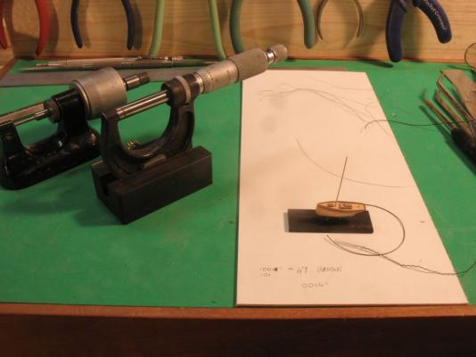
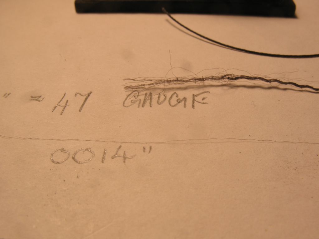
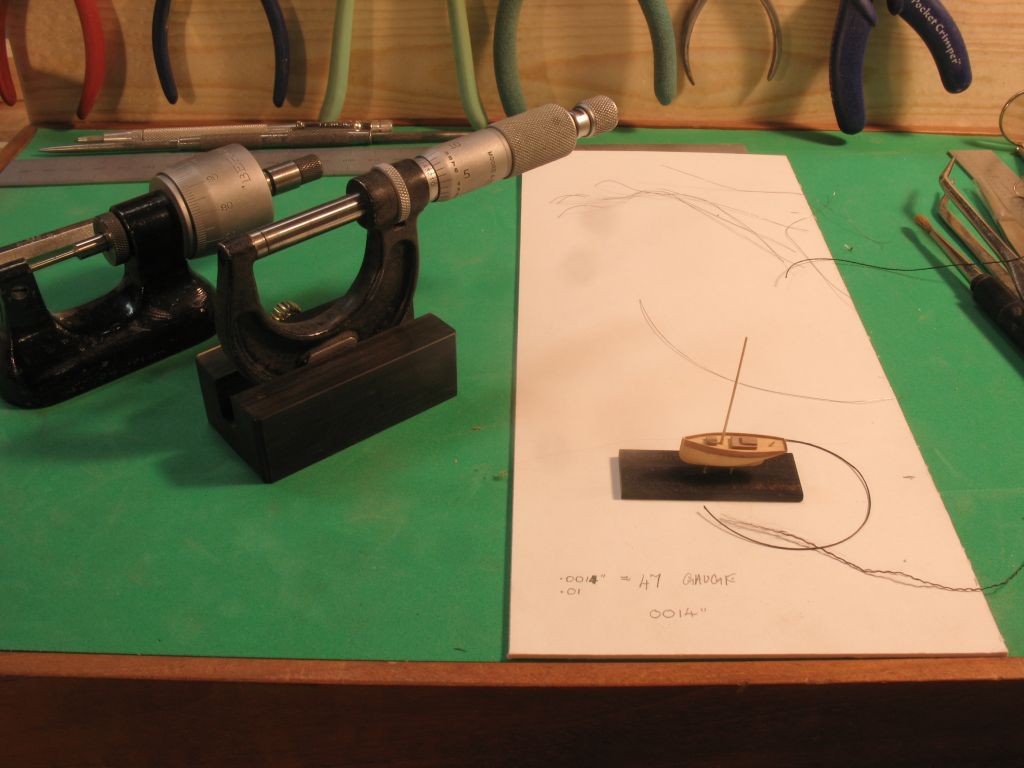
Adeline, the pencil is a regular full size drawing one. your comment reminded me that I did make a couple of yellow pencils for a customer survey station about 15 years or so ago, My son has those pencils now they are about 5 feet long about 3 inches in diameter. Thinking about fine line for rigging it occurred to me that most threads are made from a number of smaller strands. I first took some .025mm nylon canvas thread and unraveled it (tricky) but once the end is spayed you can pull out a strand with a pair of fine tweezers. the brown and sharp gauge puts the .0014 at 47gauge I have a bench micrometer that is metric but the charts I have for wire gauges are all in imperial so I made a small stand for my imperial Moore and Wright 1" micrometer I need a fixed micrometer to measure the tiny stuff this way I can adjust the micrometer until the thread just slips between the anvils. The metal strands in the background are 35 gauge. I laid one of the strands on the deck and it looks right for the fine standing rigging plus 500 times .0014" is .7 of an inch at full size so it is still a tad on the large size. The key will be tying a knot. I have not tried that yet. Time for some shut eye. Michael