HOLIDAY DONATION DRIVE - SUPPORT MSW - DO YOUR PART TO KEEP THIS GREAT FORUM GOING! (Only 72 donations so far out of 49,000 members - Can we at least get 100? C'mon guys!)
×


michael mott
-
Posts
5,200 -
Joined
-
Last visited
Content Type
Profiles
Forums
Gallery
Events
Everything posted by michael mott
-
 Bedford welcome to the "you cannot have too many clamps club" no matter how many clamps you own, no matter how many different types and sizes you have, ask me how I know.... you will never have enough, there will always be that moment if I just had one more ! Your planking looks very nice. Michael
 -
Excellent job on the hatch Rusty. the rest is not to shabby either ;>) Michael
-
Jesse, thanks you and welcome, I suppose I really must do a little work on the model before it gets completely buried in dust. perhaps today I will squeeze in an hour or two. After all it is something I can work on in the warm comfort of the kitchen table now that I have a small portable workbench. Michael
-
John, yes I was very happy to hear from Roger. Dan, I just make time and my wife is very understanding, I do all the maintenance and building and do the dishes. I did not get much sleep last night because I was out putting wood in the stove every 2 hours, a better wood stove would be good. Pete thanks and welcome. Ed, Thanks for looking in, The method will be proved one way or another, your own dedication to research and accuracy has been one of the things that has inspired me to have a go at making an accurate model of a real existing classic boat. I am looking forward to finding out a number of various sizes and distances from Roger. I am particularly interested in the sizes of the frames, beam width, free board and the shape of the stern under the waterline. One of the things that I am most interested in regarding the build, is bending the frames inside the ribbands rather than over a solid form., I might have to pre bend some but I will find out soon enough. Roger informed me that the planks are affixed with iron nails, so copper will work on the model as a substitute. It will be interesting to see if the nails are bent or were fixed with roves. Tom, Yes I agree good and bad but I have not given up hope of hearing from the owner of Floss yet, the good news is that the hulls are identical and were built at the same time, the only difference being the engines, there does seem to be a good deal of info about the Buffalo as well. The engine will certainly be a bit of a challenge but I can be like a "dog with a bone" sometimes. Regarding a visit to the real boats it is on the other side of the country and travel here is not cheap, it would definitely make a great holiday destination next summer though. Michael
-
Mick I think the red looks good. I have noticed that the dark colours show up minor imperfections in surface finishes more than light colours, so a dark primer is best for doing the fine finish sanding. Michael
- 170 replies
-
- 1
-

-
- thames barge
- billing boats
- (and 1 more)
-
Well I did not get to work on any models today see my post about Maria. However I had a wonderful conversation this afternoon with a Roger Dyment who is the owner of Skipjack the sister to Floss, the boats are identical except for the engines, and since i have not heard from the owner of Floss I think I will be building her sister. Roger told me that he would be happy to give me any assistance, and take photographs of the hull as she is out of the water for winter. Roger told me that about 70% of the hull timber is original, and although the Buffalo Engine is not it is the correct vintage here is a link that roger passed on about Skipjack Michael
-
SS Vinal Haven by TBlack - FINISHED
michael mott replied to TBlack's topic in - Build logs for subjects built 1851 - 1900
Terrific work Tom. Looks like you are getting pretty cozy with the brass work as well. Michael -
Speedy and good looking work there sir. Michael
-
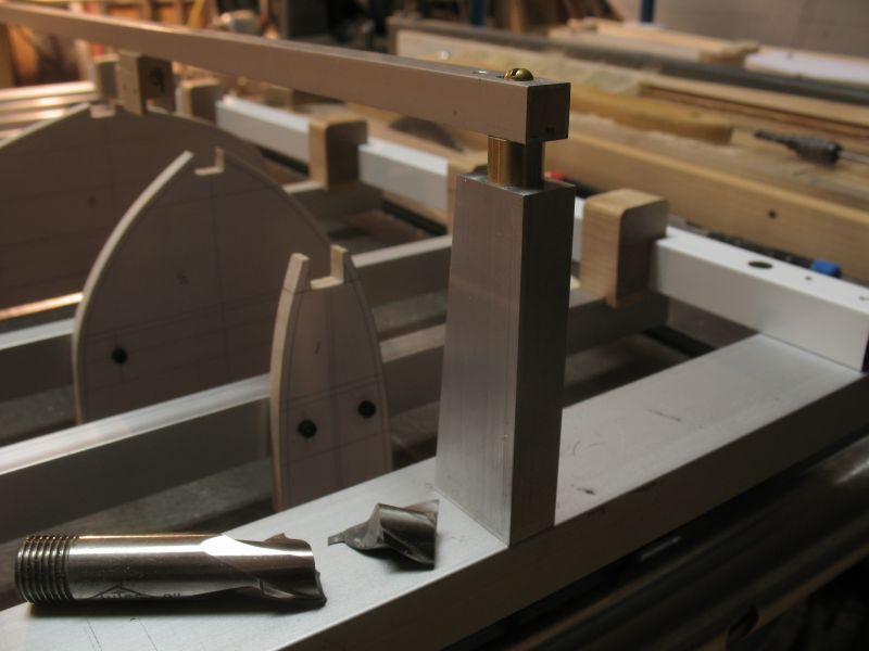
Bob thanks, I can tell you that fiddling around with this frame has given me a whole new appreciation for all the builders out there building the fully framed models I would be forever turning the thing over to shake out something I dropped into the depths. John, not a chance that this will take away too much from the cutter, I just wanted to get a bit of a start building the board and doing some tests while researching the launch. Floss Part 4 Made one of the classic mistakes today, I measured off one of my prints and not a dimension, and the scale was off on the print. hence the brass spacer. I kept looking at the keel clamp next to the drawing, and the keel itself all were fine it was a different print that the spacer stand was on. The other screw up today was breaking this 5/8ths end mill while making the aluminum keel clamp supports that were too short. I had used a piece of aluminum the same thickness as the piece being machined so the piece was not tight enough in the vice. I was using a climb cut and as soon as the cutter began it started to pull the metal toward itself and before I could turn off the mill the end mill snapped. The wooden keel clamps are made from a piece of white Lilac that I cut in 1974 lovely wood. The keel test piece is maple and the width is 11/32 The gripe is balancing on the rest of the test keel Michael

-
Papegojan 1627 by mati - FINISHED - 1/48
michael mott replied to mati's topic in - Build logs for subjects built 1501 - 1750
Matt, Thank you for your prompt explanation. Michael -
Papegojan 1627 by mati - FINISHED - 1/48
michael mott replied to mati's topic in - Build logs for subjects built 1501 - 1750
Forgive my ignorance but what is "Microcristal Wax" ? Michael -
I just cannot imagine it Tom. She is looking a lot better now though. The walls behind the model look like they are plastered stone? Michael
-
Mark, Pete, Tom, thanks for looking in. Mark, some of the building boards that I have seen on this forum were my inspiration, there are some nice rigs out there. Pete, I am hoping that this set up will be flexible enough to use for a number of small boat hulls. Tom, Yes you are correct the drawings I have done so far put the hull at 28 1/2 inches with a beam of 7 1/2 inches and 2 1/2 free-board at midships with a draught of 1 11/32. these dimensions are subject to change as I get more accurate information hopefully from the present owner. My other route would be to contact the owner of Skipjack which is the sister boat albeit with a bigger engine, a Two Cylinder Buffalo. Michael
-
Very nice work Rob. Michael
-
This is an intriguing build, I am looking forward to seeing how you "pull it all together" Michael
-
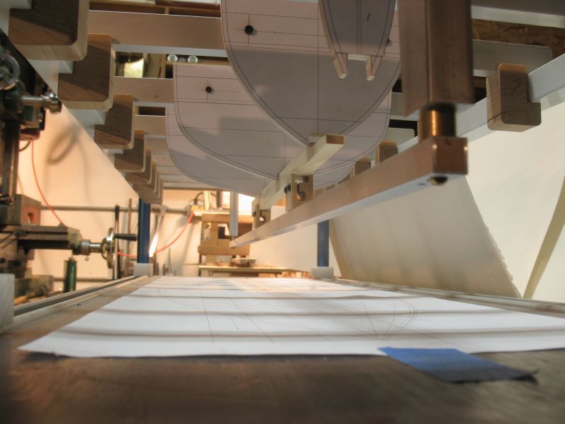
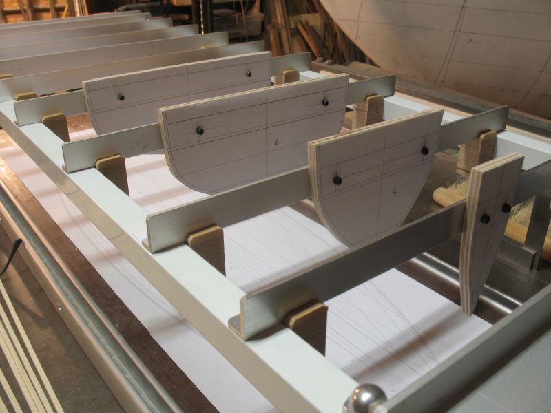
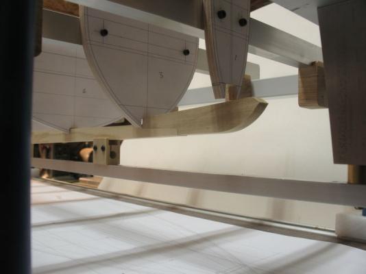
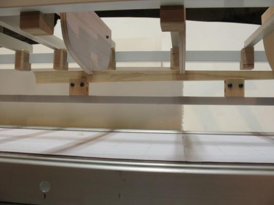
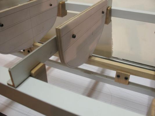
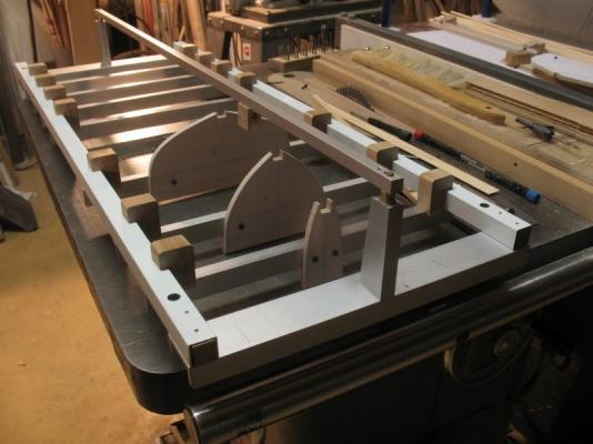
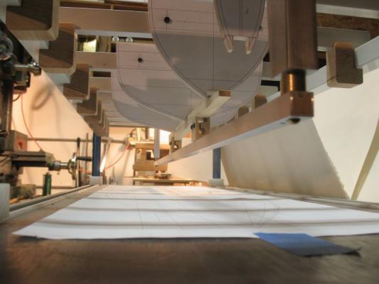
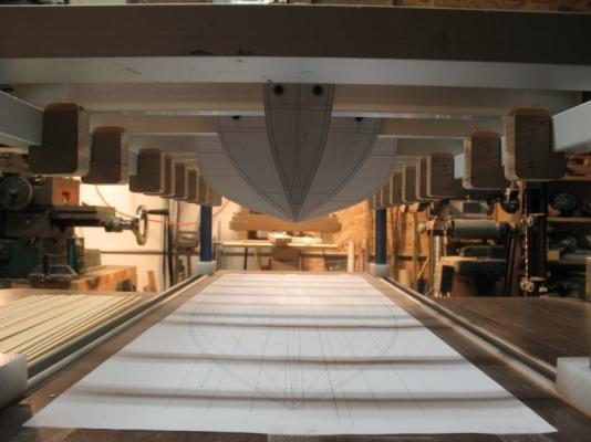
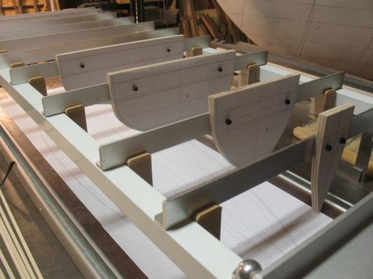
Floss Part 3 For the first test I am setting up 4 moulds and the stem, gripe stem knee and a section of keel. The moulds are bolted to the cross beams with 4x40 cap screws, The strips are 1/8th by 1/8th white pine that I will try as ribbands for the first test I have discovered that I need to add a little side to side movement to fine tune the moulds to the centreline. The moulds on the cross beams are positioned using some small engineers squares. Michael
-
What a graceful shape, she is looking good Tim. Michael
-
Ed, thank you for your detailed explanation, yes windows XP is a stable platform simple but good enough for me, I think our desktops are similar. I also have a large screen, I cannot see the small screens clearly enough. Michael
-
Pete, this looks really interesting I will be following along, Nice looking drawings you have there. Michael
- 296 replies
-
- 1
-
-
- herreshoff
- buzzards bay
- (and 1 more)
-
Symiaki Skafi by stelios
michael mott replied to stelios's topic in - Build logs for subjects built 1851 - 1900
Stelios, it looks like you are almost finished and she looks great. Michael -
Ed I am learning a great deal working through your comments about how you are designing and Lofting your plans. I am curious about what programs you are using. I am familiar with Corel Draw 11 and Autocad Lt 2000 and I have been applying some of the same techniques to my own drawing based on your lead. Michael
-
Piet the model is looking great. regarding small nut bolt and screws check this site their prices are quite reasonable and good quality. Michael
-
Great work Neal I like the added metal work, it is great when one can use real nuts and bolts. Michael
-
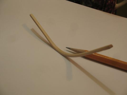
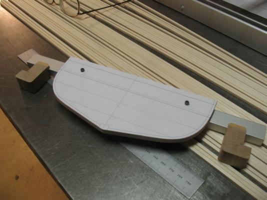
Mark, Crackers, welcome. I hope that I can contribute some interesting methods for others to try, although I'm guessing that most of this will have already been done by somebody else. I will be setting up three mould forms and a stem to test the principle of working with this frame. 1. To see what sort of dimension and strength that the ribbands will need to be. 2. To determine if the temporary attachment method will in fact work. 3. To find out if the method of placing the planks to the ribs will also work satisfactorily. 4 To test the mould and stem clamps. The picture shows frame number 17 test this was done using the pins on the homasote board, it is clear Fir with the grain laying flat across the width of the frame. I will need to choose carefully the wood and the grain direction for maximum strength. I have been able to get an email forwarded to the present owner of Floss, and am hoping it proves to be fruitful. Michael