gjdale
-
Posts
4,894 -
Joined
-
Last visited
Content Type
Profiles
Forums
Gallery
Events
Everything posted by gjdale
-
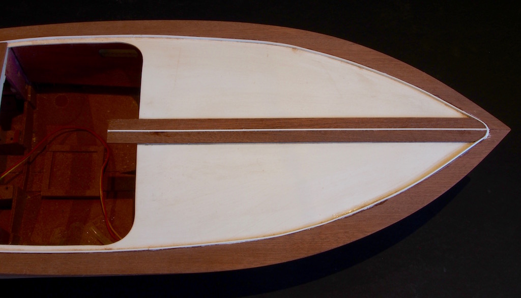
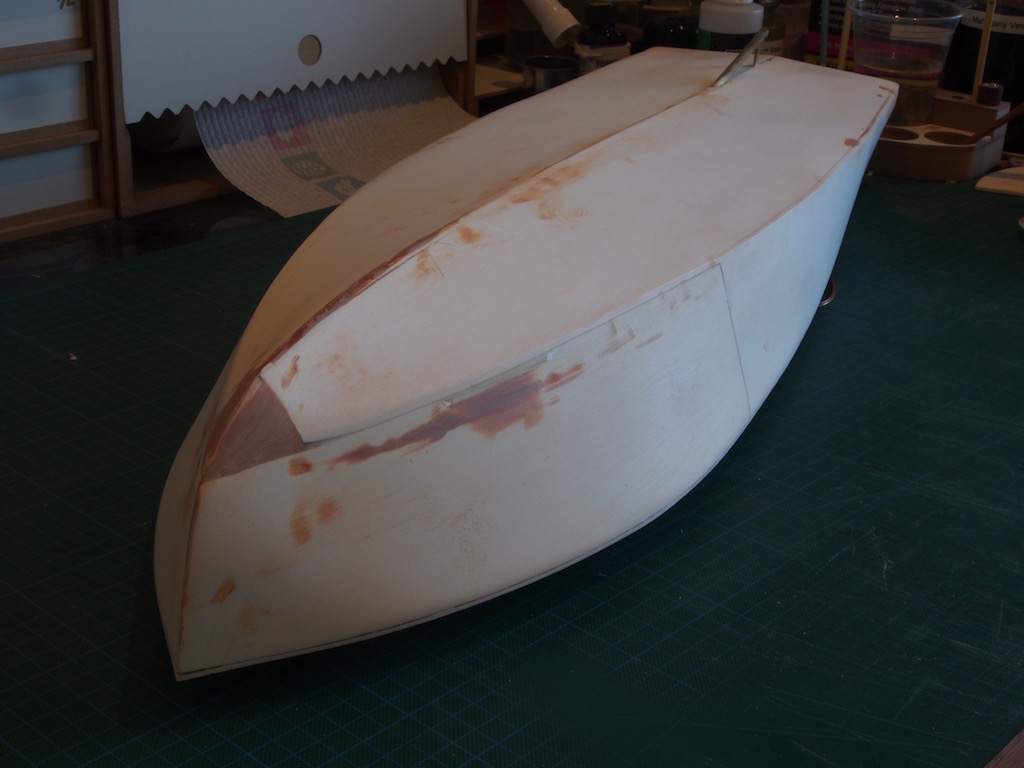
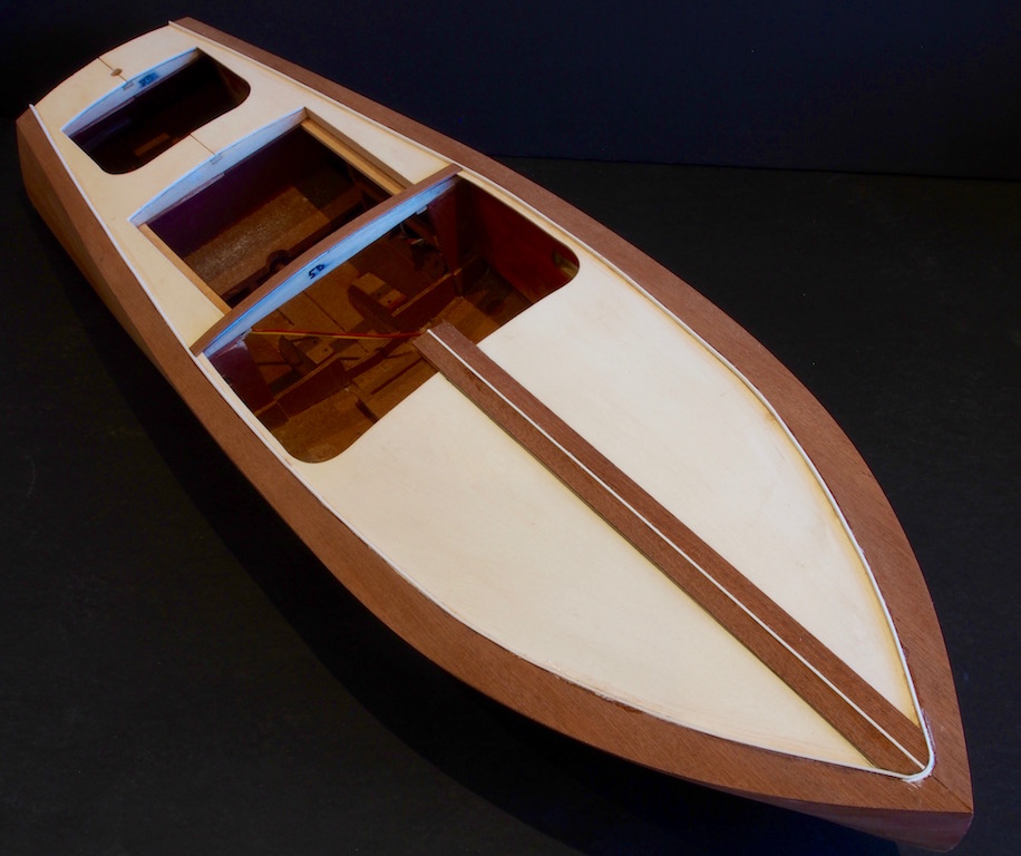
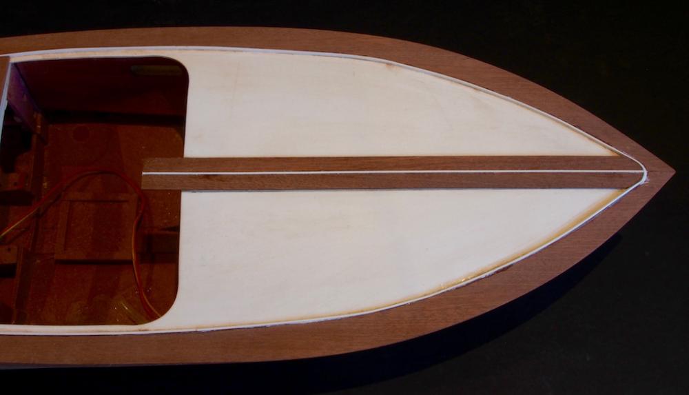
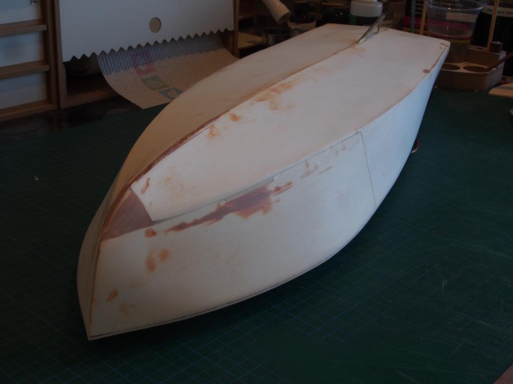
 Planking Planking the hull turned out to be a little trickier than anticipated, and included a “near disaster”. Planking the first side, I followed as closely as I could the lining out marks, having first tapered the planks to fit against these. The problem was in the lateral bending of the planks. Ideally, they should have been spiled. However, the planks provided are not sufficiently wide enough to spile (and I didn’t have any sheet stock that I could substitute). The kit planks are also wide enough that edge bending is very difficult, if not impossible. The result was a less than even surface. On the second side, I decided to adjust the lining out marks to allow the first (chine) plank to fall naturally – which took it exactly one strake higher on the lining out marks at the bow. This meant that I had to insert a wedge shaped piece below this plank, but the remaining planks on that side went on somewhat more easily than the first side. The result also meant that I managed to maintain alignment of planks on either side at the bow. The near disaster came when I went to give the hull an initial sanding to even out the surface. Following the lead of others who have gone before me, I broke out the powered mouse sander and set to. I must have been a little too aggressive in one place because I suddenly noticed that I had sanded through the entire thickness of the planking and could see the white plastic showing through. Oops….. I also discovered that on the other side, one plank had developed a hole – not sure how, but the timber is very dry and brittle. Hmmmm, two repairs to make! My first thought on repairing these was to use epoxy putty, but one of them was quite a large area and was going to look dreadful. After sleeping on it for a couple of nights, I decided that I would remove a section of the planking and patch it with new planks. Another few days to consider exactly how to achieve this, and I finally gave it a crack yesterday. I used a mini circular saw blade held in the Proxxon rotary tool and gently made some “stop” cuts at the extremities of the section I wanted to remove. I was then able to insert the blade of a No.11 Exacto knife and prise the damaged planking free. A quick clean up with the drum sander in the Proxxon to remove the residual glue and it was ready for the new timber. I took my time in shaping in the “patch” parts, and even managed to spile some thinner sections to get a very close fit. I also used some epoxy putty (Milliput) to blend the area at the bow where the timber transitions to the plastic sheeting of the hull bottom. After a careful HAND sanding, I was quite pleased with the results. Here are a couple of views of the completed repair job (forgot to take pictures of the “before”). And here is a close up of the bow, showing the alignment of the planking. The stem is not perfect, but as it will be covererd later by the cutwater, I’m happy with it as is. Then, at last, it was time to start on the deck planking. The process starts with the attachment of the edge or margin boards. These are die cut parts, slightly oversized, and are relatively easy to fit. Once in place, the outer edges are sanded back flush with the sides, and a strip of white “caulking” (.04” x .08” styrene) is applied to the inboard edge. The next step is to place the centre plank on the forward deck. This requires that a length of caulking be sandwiched between two planks (3/8” wide mahogany), then shaped to fit the bow and fixed in place down the centreline. Compared to the hull side planking, this was dead easy! The remainder of the deck planking will follow a similar pattern, with a plank being glued to a strip of “caulking” before being shaped and affixed as a pair. I’ll be back when the deck planking is complete.
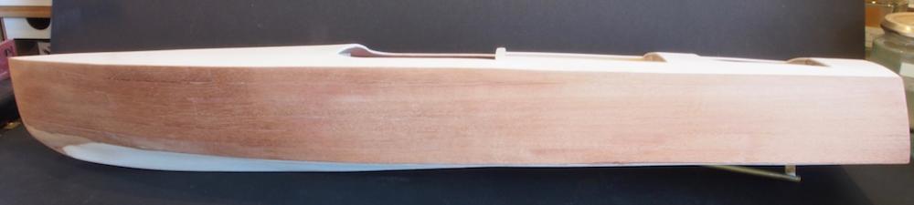
- 339 replies
-
- 19
-

-
- dumas
- Chris-Craft
- (and 3 more)
-
Glad you found that info Gary. It seems a long time ago now, but I do recall B.E. providing some extra info.
-
That's a great looking sail there Mobbsie. I think the seamstress deserves a double grog ration!
- 129 replies
-
- 7
-
-
- armed launch
- panart
- (and 1 more)
-
Granado is looking splendid Bob. Sorry to hear about Cheerful, though I have no doubt you will manage her repairs so that no one will ever know. Now, about that case...........
-
I've encountered a similar issue JP. My solution was similar to Jay's - insert something of slightly smaller diameter in the other end of the collet (eg a drill bit, or piece of brass/steel rod), and then GENTLY tap the end. It doesn't take a lot of force to free the bind. Sometimes just tapping the inverted "assembly" on the workbench top is sufficient.
-
I'm finding this a really interesting read Slog. Thanks for taking the time to share so much detail and your techniques learned through experience. Your "traps for new players" comments are particularly useful. One day I will have a crack at one of these..........one day........... So many models, so little time!
- 244 replies
-
- 5
-
-
- borodino
- dom bumagi
- (and 1 more)
-
That's a bummer Kevin. Welcome to the club, which has a very large membership!!! Many of us have shared your pain. I hope you manage to work out a fix to your satisfaction.
- 1,319 replies
-
- 4
-
-
- caldercraft
- Victory
- (and 1 more)
-
Thanks for looking in Lawrence, To answer your question, a brass rod links the horn of the servo to the rudder arm on the rudder post. It's a very simple affair. I'll try to remember to take some pictures of it next time I connect it all up.
- 339 replies
-
- 3
-
-
- dumas
- Chris-Craft
- (and 3 more)
-
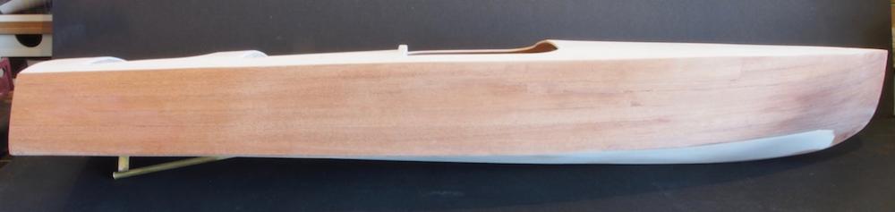
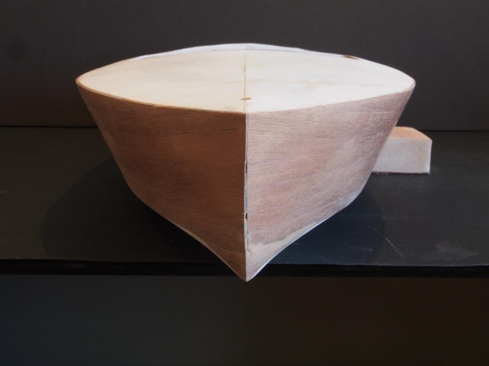
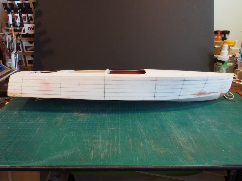
Once again, many thanks for all the kind words and to those who hit the 'like' button. Progress has been slow lately due to other commitments, so only a mini-update this week. Installing the sub-decking was straight forward: Took the opportunity to fill some of the dings in the hull using a two-part Epoxy putty (Milliput Terracotta) and she is finally ready for planking. The instructions would have you just lay complete planks the length of the hull, from the chine up to the sheer. I tried that on one side and wasn’t happy, so ripped it all off again. Then I lined-off the hull using tick-strips in an attempt to do better by tapering planks fore and aft and having the same number of strakes throughout. Here is the lined-off hull: So far, the tapering seems to be working quite well. I've been using a miniature plane to taper the planks and have to say, it beats the pants off sanding! Much easier and far less mess. The supplied planks are not wide enough to spile, so I will likely use some shorter plank lengths in addition to tapering, to cope with the bow curvature. I got as far as laying three strakes the second time around before I ran out of CA kicker – a real must for this process. So, it’s back on hold until I can pick up some more supplies. More pics once substantial progress has been made with the planking.
- 339 replies
-
- 19
-
-
- dumas
- Chris-Craft
- (and 3 more)
-
Count me in for two Chuck! (One for me and one for my Dad).
- 269 replies
-
- 6
-
-
- Queen Anne Barge
- Syren Ship Model Company
- (and 1 more)
-
Welcome back Gerhard. Nice to see your Baby taking shape.
- 72 replies
-
- 6
-
-
- bootlegger
- speedboat
- (and 1 more)
-
Wonderful work, as always, Nils.
- 2,625 replies
-
- 6
-
-
- kaiser wilhelm der grosse
- passenger steamer
- (and 1 more)
-
Don't forget Mark, that Sherline offer the "sensitive drilling attachment" accessory. A very useful offering.
-
Ah! Proof of life! Nice to see an update Wayne. Planking seems to be going very well.
-
That's kinda what I had in mind Mark. I think Ed's were more like a miniature version of a "Gunter Batten" if I remember my damage control training correctly. Oh, and let me add a vote for the Sherline mill. You won't regret it!
-
Looking great Slog. I'm really enjoying following your work on this.
- 244 replies
-
- 5
-
-
- borodino
- dom bumagi
- (and 1 more)
-
Nice work on the jigs Mark. Those spales have come in handy a number of times - you'll wonder how you ever got on without them. Re your first jig in your post, I wonder whether some telescoping brass tubing (round or square) might achieve the same aim?
-
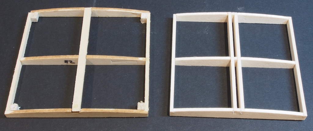
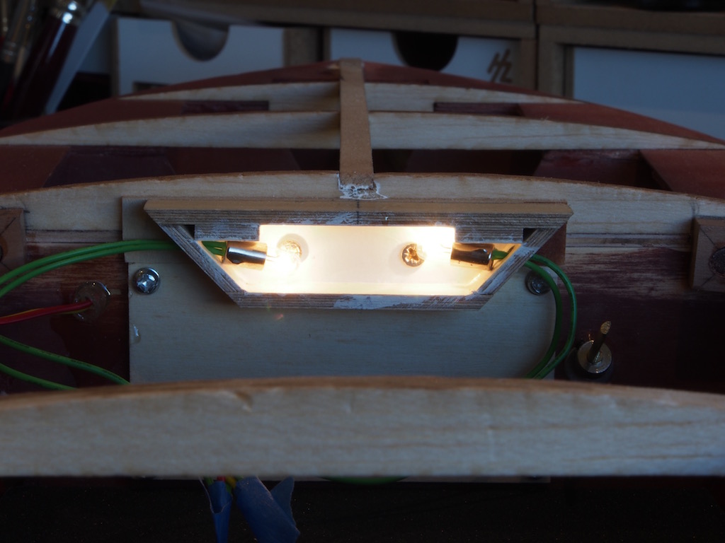
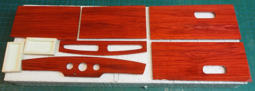
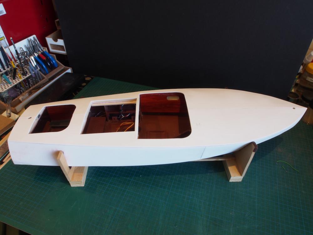
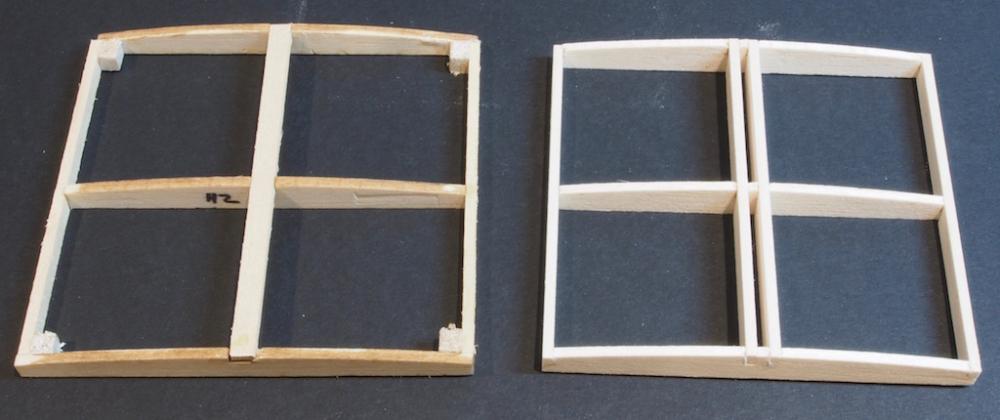
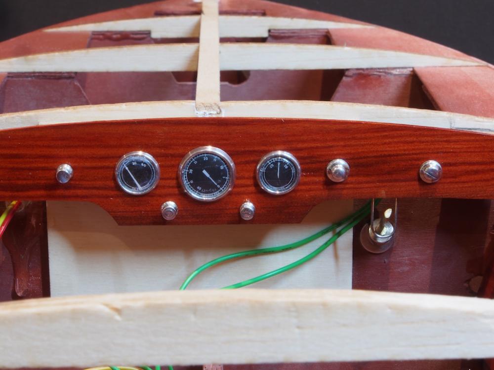
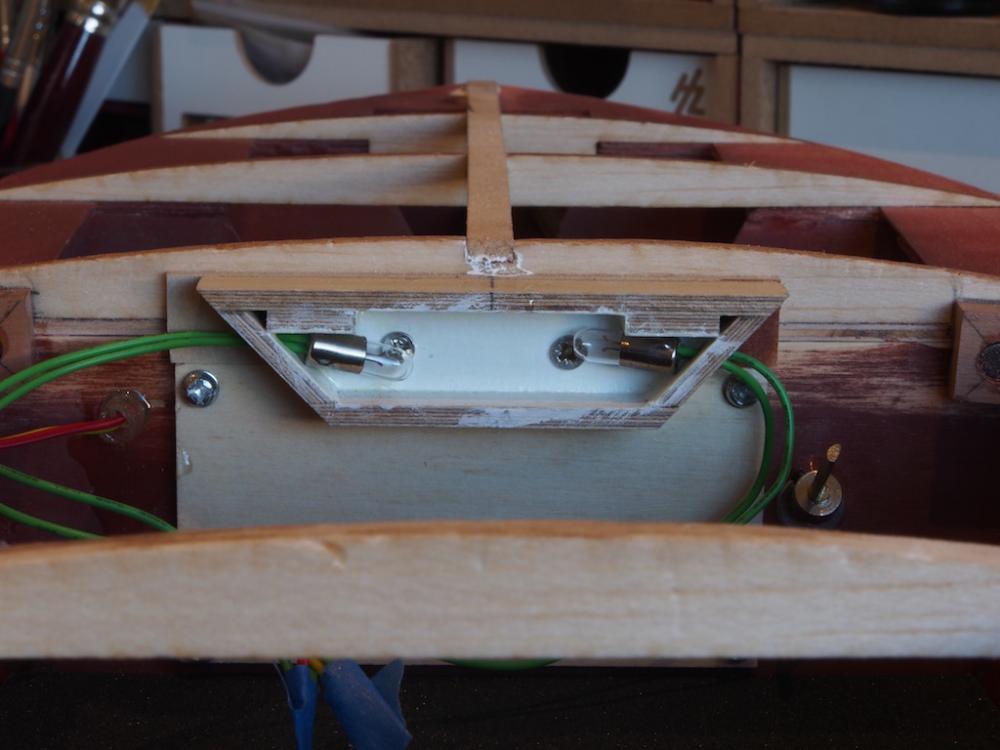
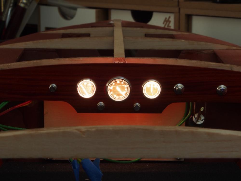
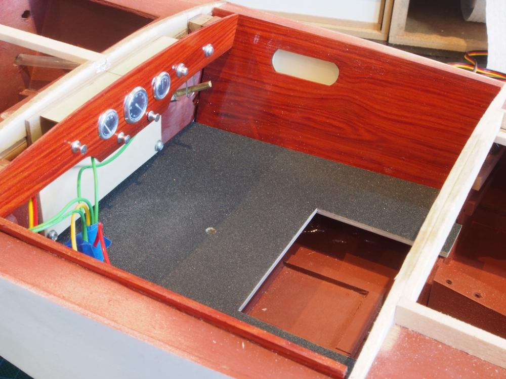
Thanks very much Mobbsie, Popeye and Bug, and to all who hit the 'Like' button. Some more progress this week, and a major milestone achieved (I think). As mentioned previously, I have decided to attempt a two-piece hinged engine hatch. I started by re-designing the hatch framing using TurboCAD and then cut and assembled the new pieces. It needed to be slightly smaller in each dimension to allow for the hinges and for some trim at a later stage. In the photo below, the original kit-supplied hatch is on the left, and the new hatch on the right. It has been built as one piece initially and will be separated into two pieces after the planking has been done. I then moved back to completing the dashboard by installing the gauges and switches. The gauge bezels are the ones that I turned Aluminium at the start of the build. The gauge faces are decals provided by a fellow modeller, glued onto a clear plastic backing. Gauge glasses are made from “googly eyes”. The knobs and switches are from MACK products. It’s not perfect, but I think it looks a heck of a lot better than the simple decal dash provided in the kit. The next job was to test the lighting for the dash. The two 3-volt lights in the light box were temporarily connected up to the power and tested – successfully! Lights off: Lights on: And with the dashboard in place: I also fitted the cockpit woodwork and floors. The floors are plastic (Sintra) and the kit instructions say to paint them grey to represent the non-skid flooring. I decided to use some wet and dry sandpaper to give a textured surface. It has been coated with a waterproof matt varnish. Here’s a couple of pics of the two cockpits. I think that I am at last ready to install the sub-decking and close this baby up in preparation for planking!


- 339 replies
-
- 21
-
-
- dumas
- Chris-Craft
- (and 3 more)
-
Thanks Mobbsie, I have some miniature piano hinge for the alternate hatch covers.
- 339 replies
-
- 4
-
-
- dumas
- Chris-Craft
- (and 3 more)
-
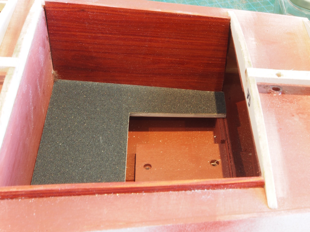
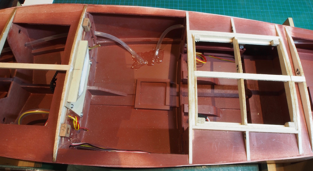
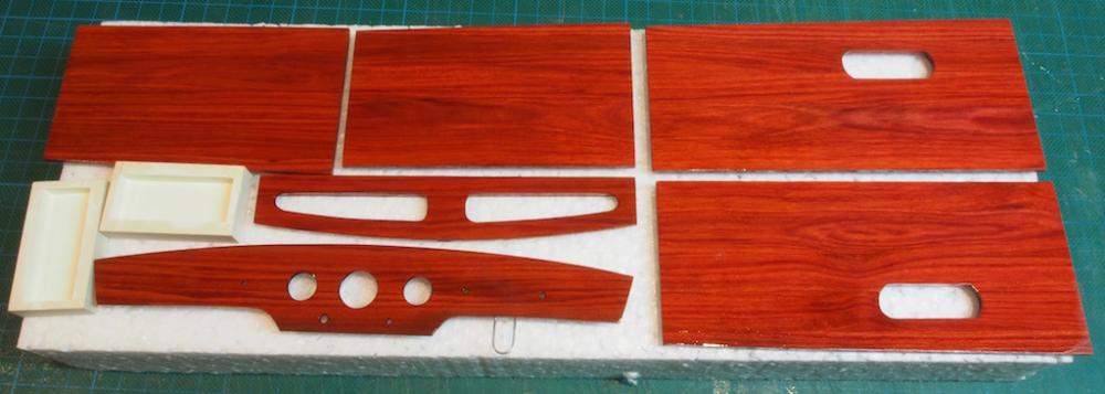
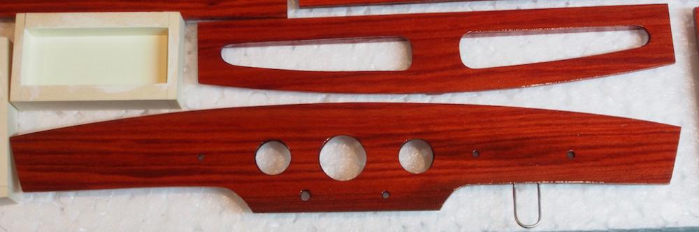
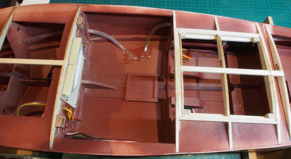
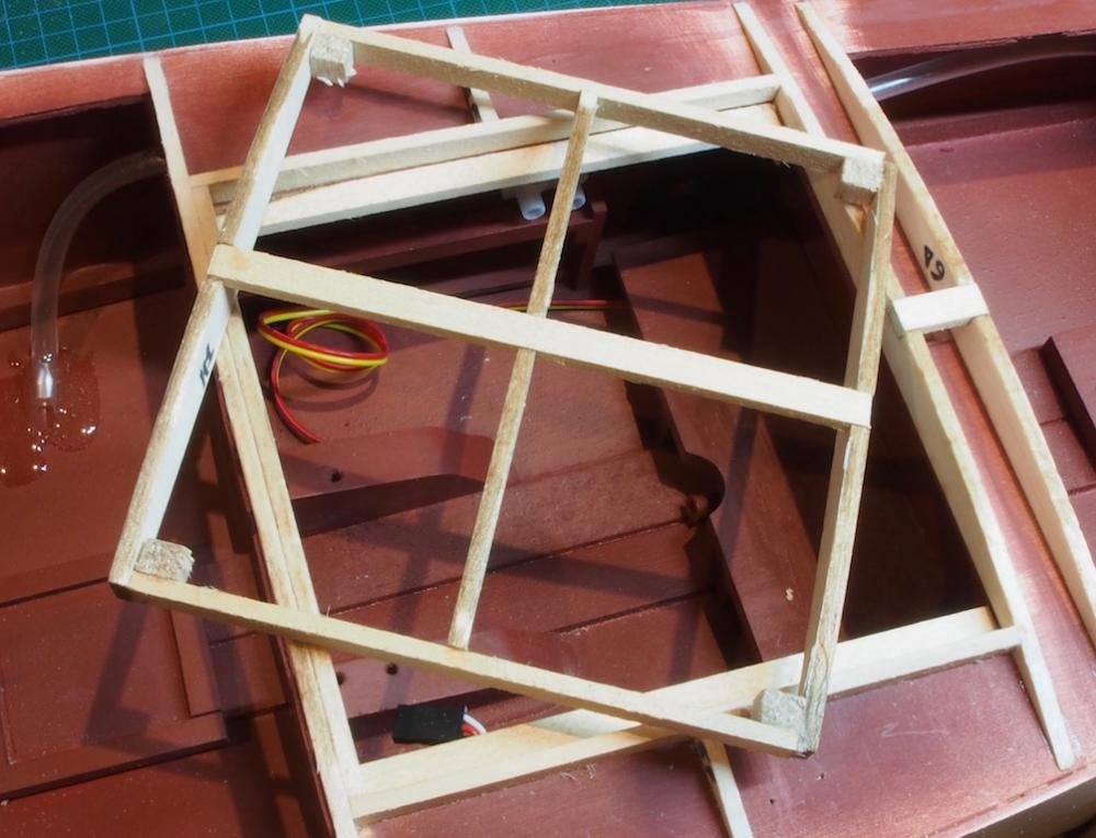
Thanks Mobbsie, Mark and Glenn for your kind words, and also to all of the 'likes'. A minor update this week: Cockpit and Engine Hatch As mentioned previously, I decided to replace all of the cockpit woodwork with Redheart. I used the kit-supplied parts as templates and cut new pieces. I also decided to follow the lead of another builder and make small glove boxes in the front cockpit sides. I cut the holes in the side panels and made up some boxes to sit behind them. The insides of the boxes have been painted with an off-white (Valejo Ivory). Once satisfied with the fit of the panels, I began applying a finish using Feast Watson Spar Marine Varnish. In the picture below, the parts have just had their third coat of varnish, but already the beauty of the timber is coming through and I think will be a nice improvement over the stained plywood from the kit. I plan on doing at least four and probably six coats of varnish on these. Here is a close up of the dash panel: I have also been continuing to plod away at the wiring. I have cut the conduit on the starboard side and epoxied the ends to the cockpit floor. This will allow some excess wiring to be pulled through under the cockpit floor. I have also run some extra conduit on the port side to take the wiring from the dashboard lights through into the bow compartments, and then down the port side, under and behind the battery, and back over to the starboard side where it will connect to the terminal post. This will ensure that the wiring for the dashboard lights is kept well away from the steering gear in the cockpit and bow compartments. I also made up the framework for the engine hatch as per the instructions. This sees the hatch as a single piece that is removable. I plan on making another hatch, in two pieces that will be hinged on the sides, as per the real boat. More on that later…. The hatch is built up in place to ensure a snug fit. Once the pieces are glued together, the completed assembly is removable. A short break now while I visit the LHS to get some more wiring, and other supplies before continuing with alternate hatch configuration. The kit-supplied hatch will remain as a 'stand-by' option. And of course, more varnishing.........
- 339 replies
-
- 21
-
-
- dumas
- Chris-Craft
- (and 3 more)
-
Chuck wrote that Practicum for Phantom, and he also wrote one for Sultana, another solid hull model. It's worth reading both as he offers a couple of different techniques as well as a host of additional information and instructions. The Sultana Practicum is available here in the NRG database of articles: http://modelshipworldforum.com/ship-model-build-and-practicums.php