
Baker
-
Posts
4,111 -
Joined
-
Last visited
Content Type
Profiles
Forums
Gallery
Events
Posts posted by Baker
-
-
-
-
6 minutes ago, Louie da fly said:
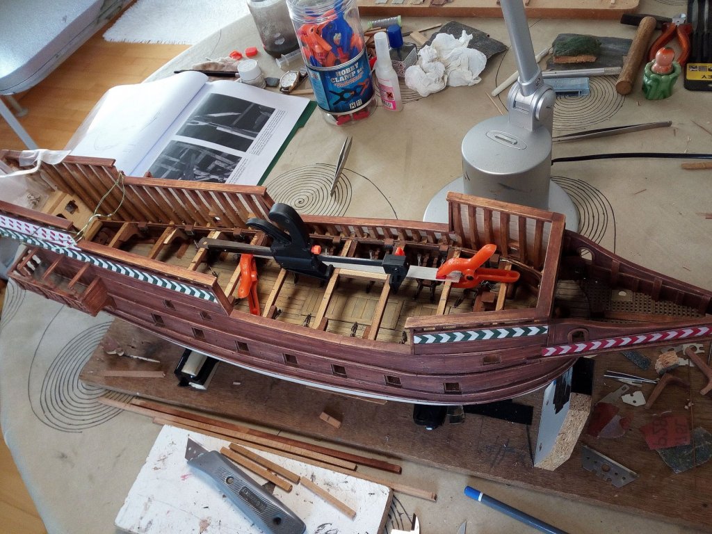
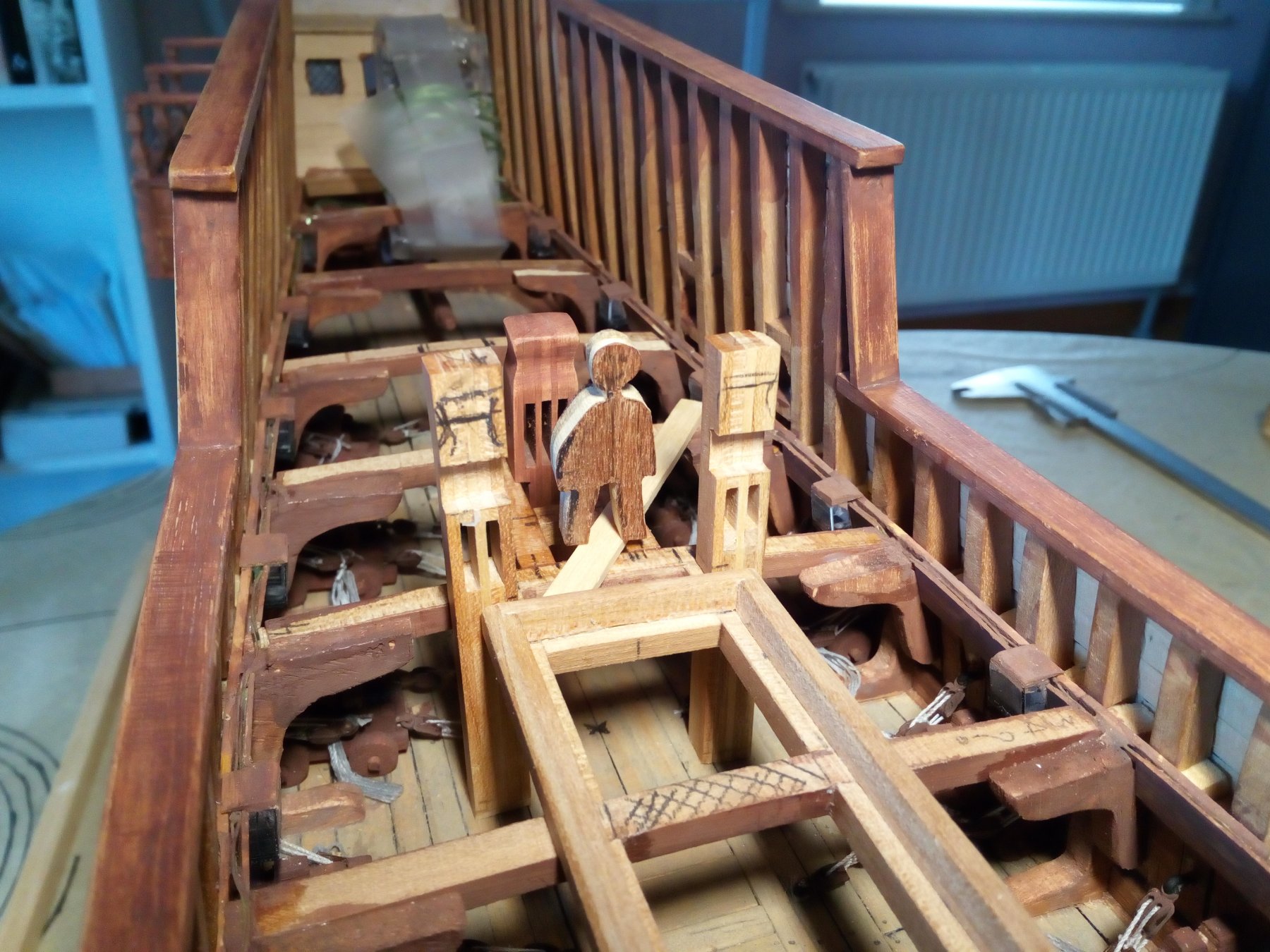
Just out of interest, how tall is that "crew member" in your last photo?
Thanks steven.
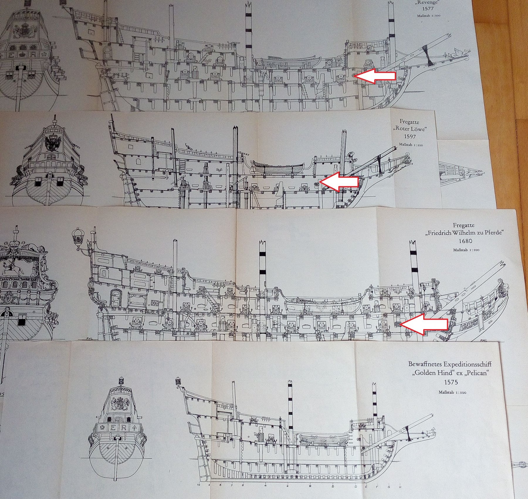
The average length of a man in the 16th century may have been 160 cm.
160 cm : 45 = 3.6 cm to scale -

Greetings Patrick
-
-
-
Hello,
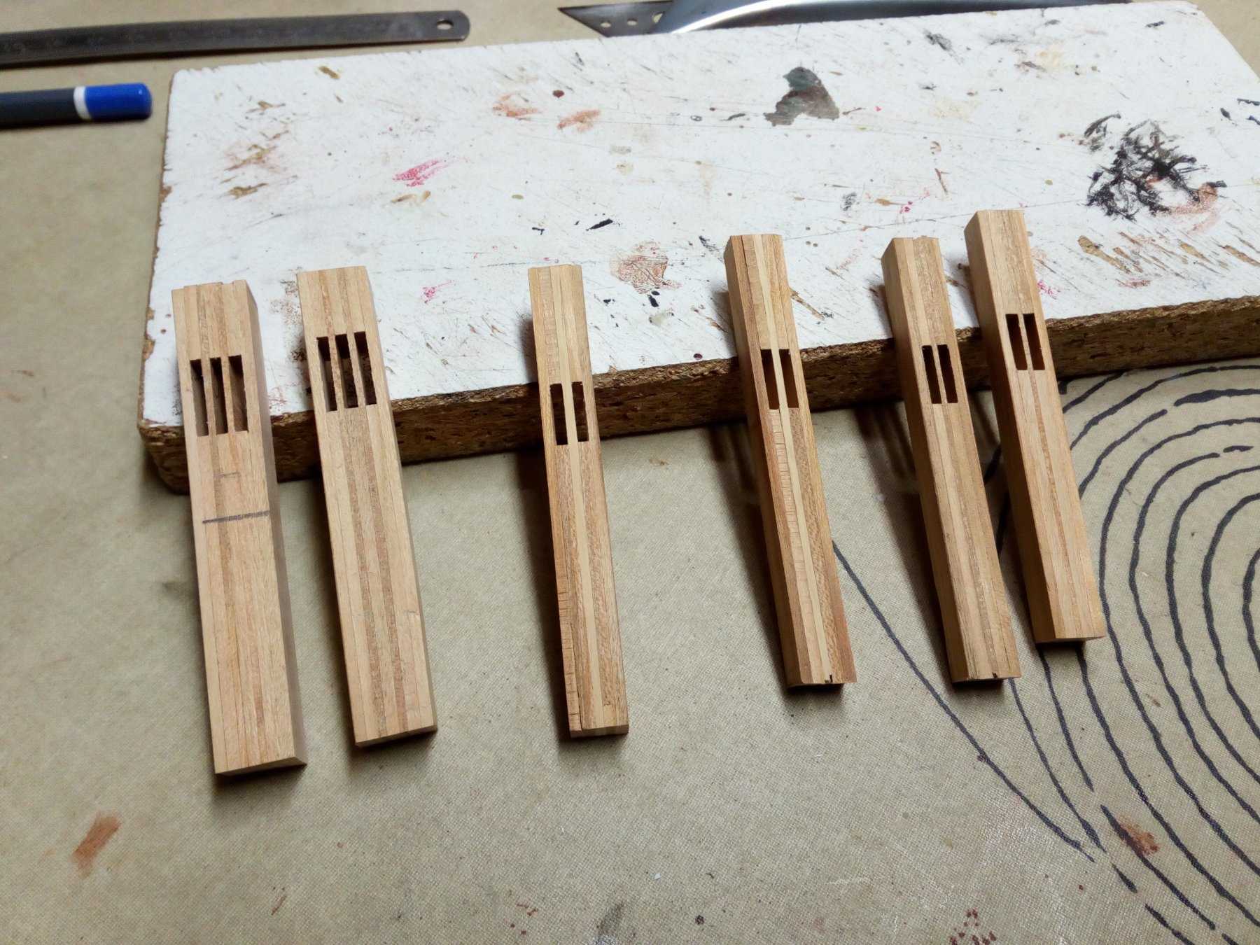
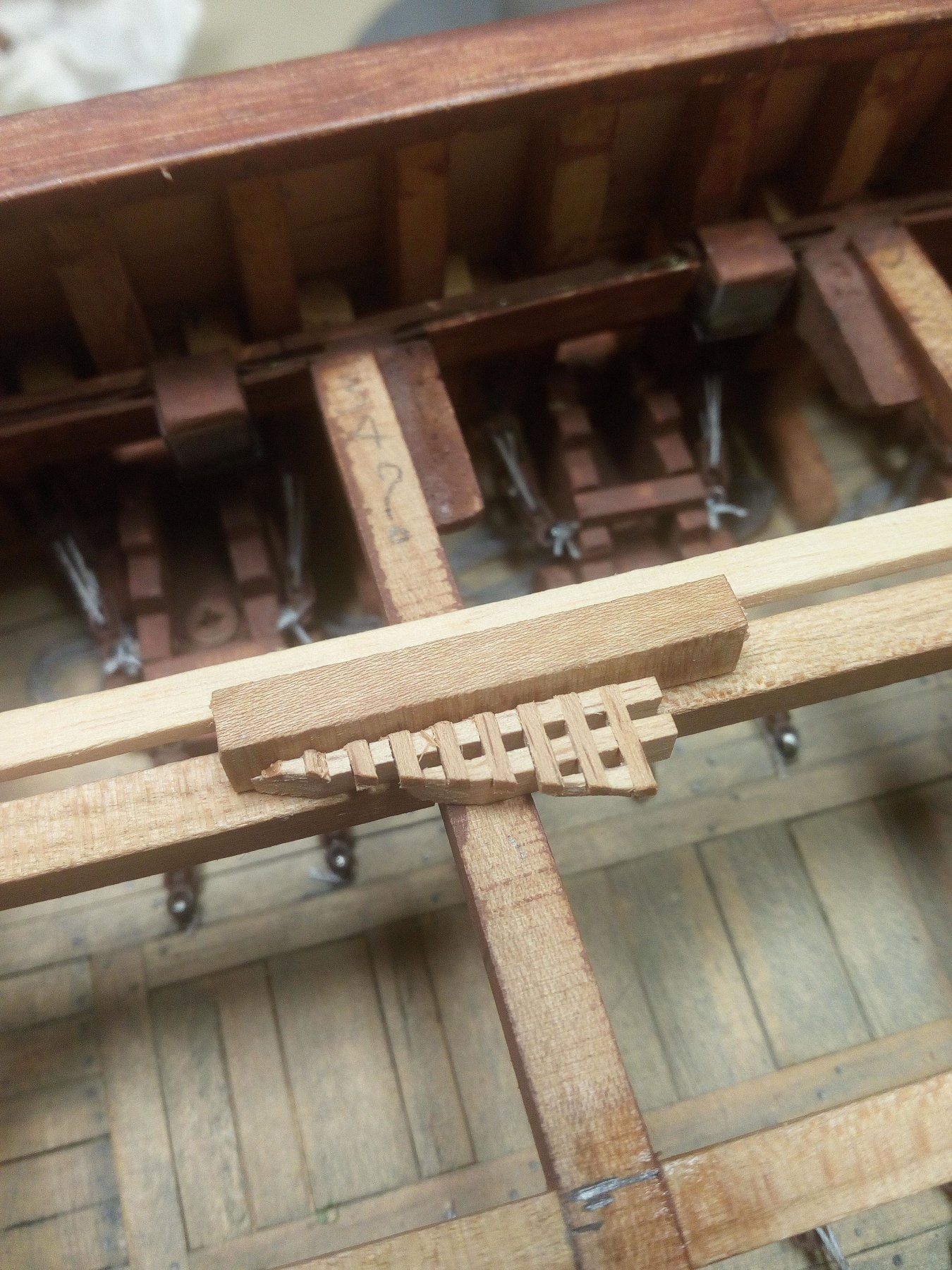
I made these pieces last week. Everything looked good, but I felt something was wrong.
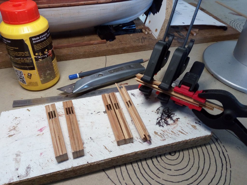
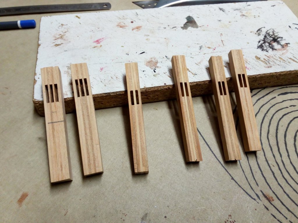
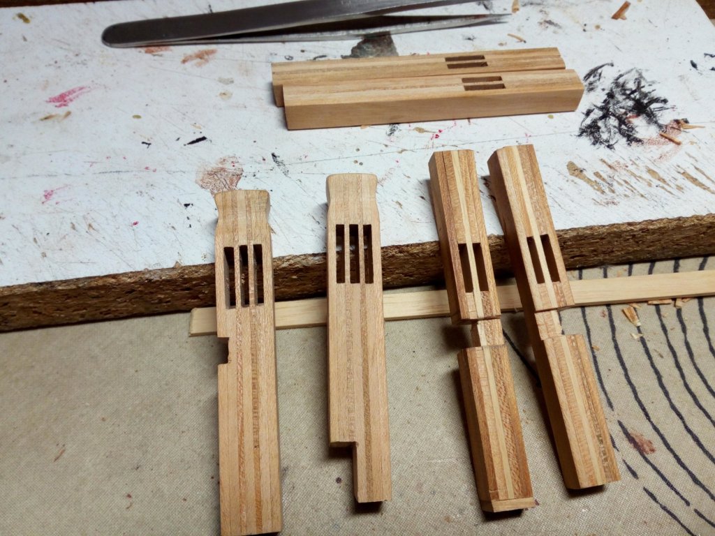
I made the pieces too big. They are not in proportion to the model.

I also discovered that my cherry wood is not suitable for this application. The wood differs too much in color
So redo. Better and smaller next time


-
-
-
-
-
Oeps
too late with my advice
-
At home now and looking on my computer (big screen) instead on my small smartphone.
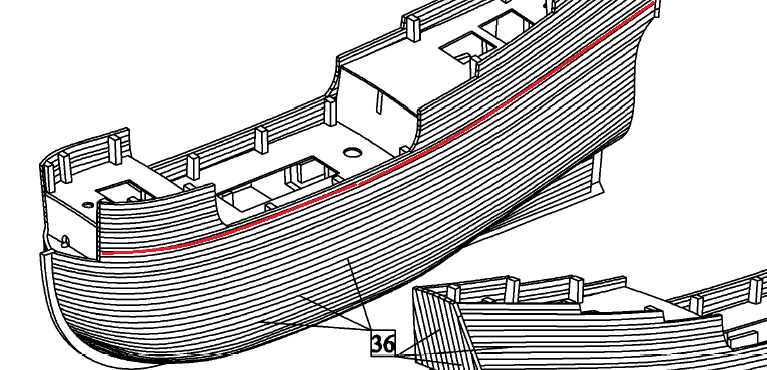
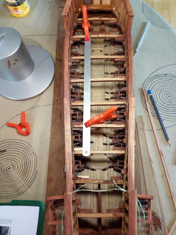
If this is your first plank. Then you can get into trouble on your forecastle and maybe on your rearcastle
On the Dusek drawings this plank stops on the forecastle and not on the bow. (Dusek drawing is from the dusek website)
ps
Nice planking on the stern
-
Best is to use filler blocks at the bow
- Shipyard sid and keelhauled
-
 2
2
-
-
-
-
-
A build log of a Golden Hind is always interesting for me.
I hope you can start soon with your model. -
Welcome back Michael.
The quality of the brass cannons looks better for me.Great work!
- EJ_L, popeye the sailor and md1400cs
-
3
-
-
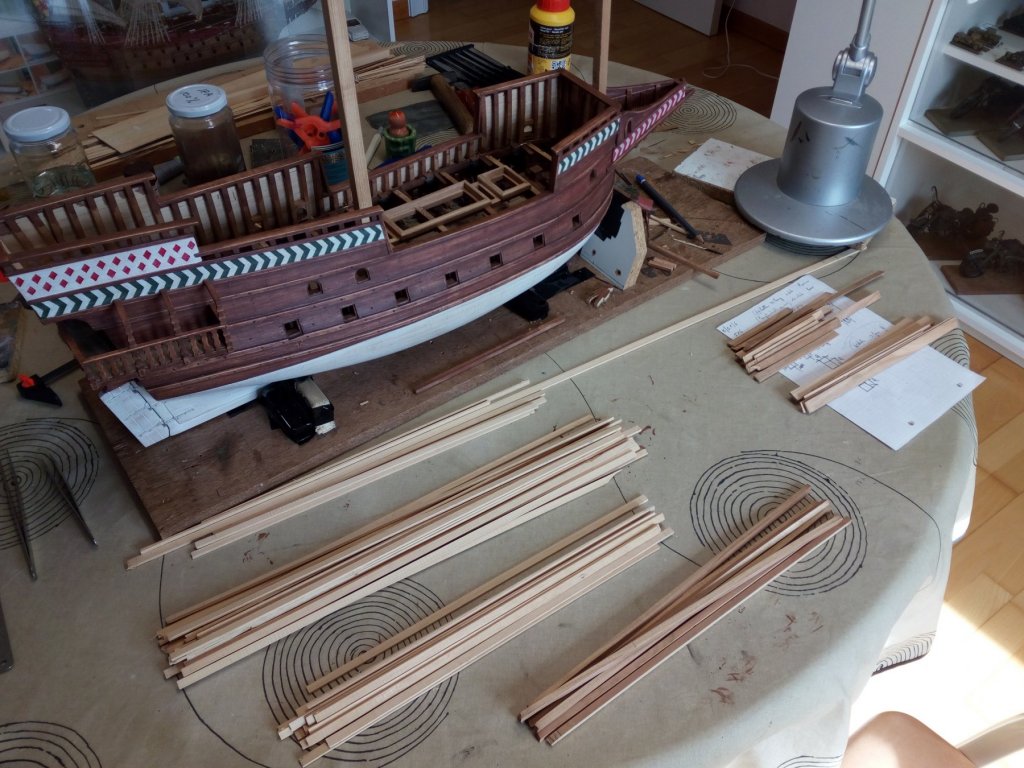
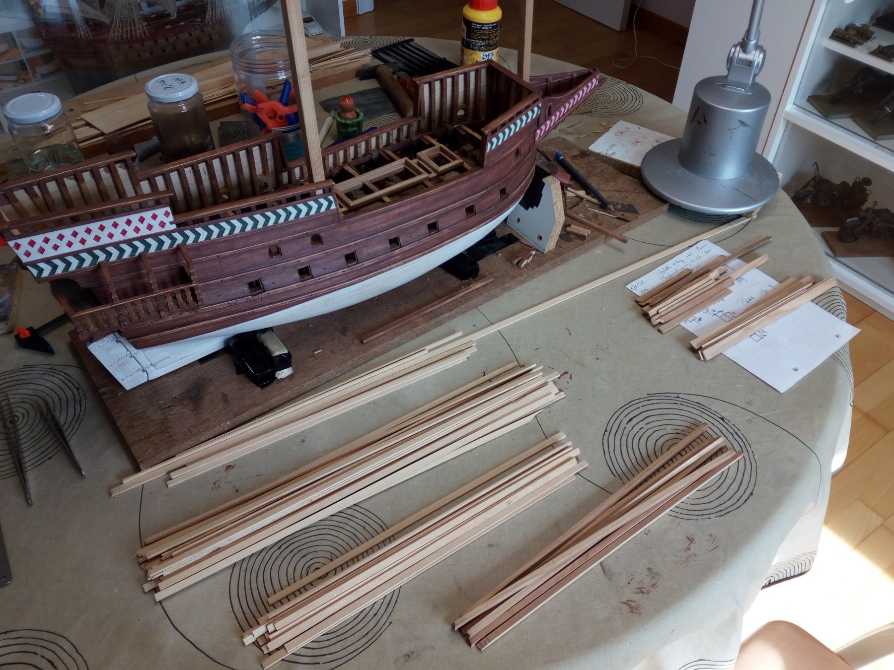
Thank you all for following and comments.
It was a productive weekend. Wood has been sawn so that I can continue to build.
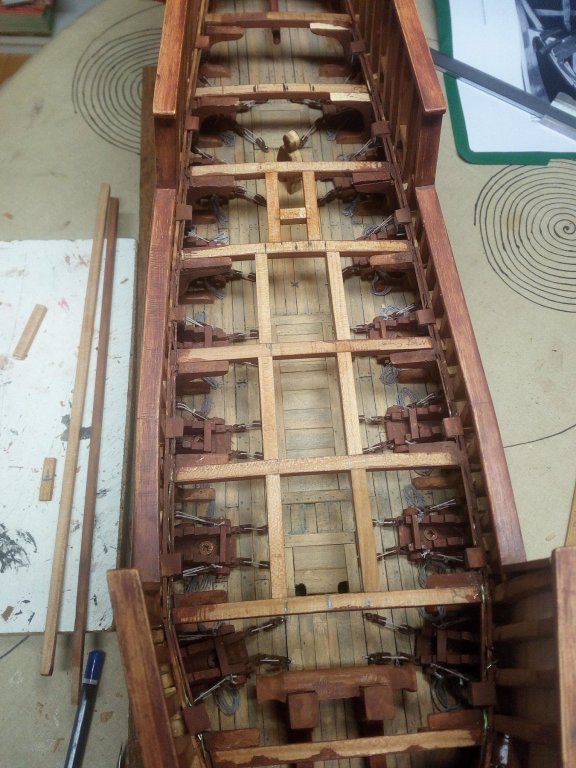
Further i thought about stairs to the underlying deck. And discovered that on some plans no stairs are provided at all.
Forget something? A mistake?Fortunately there is something provided on "my" Golden Hind

Thanks for following
-
-
Hello everybody
@Carl : Have it asked at Jan. We have the same opinion.
@ Marcus and Steven : Thanks for the comments.
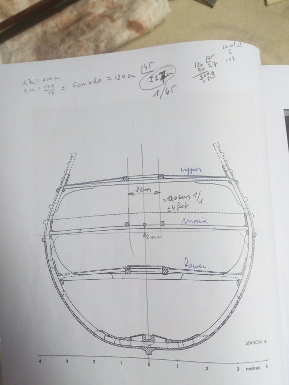
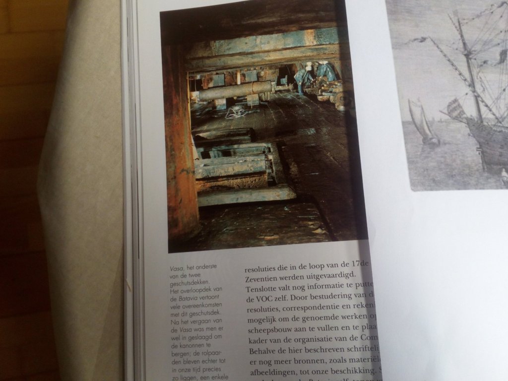
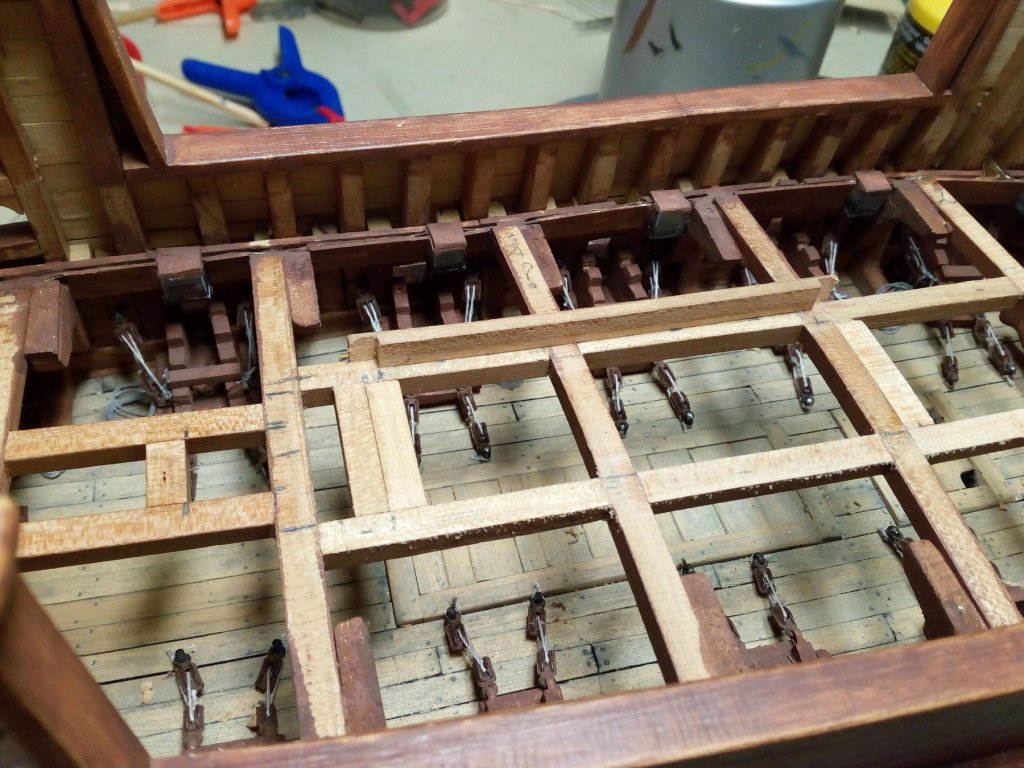
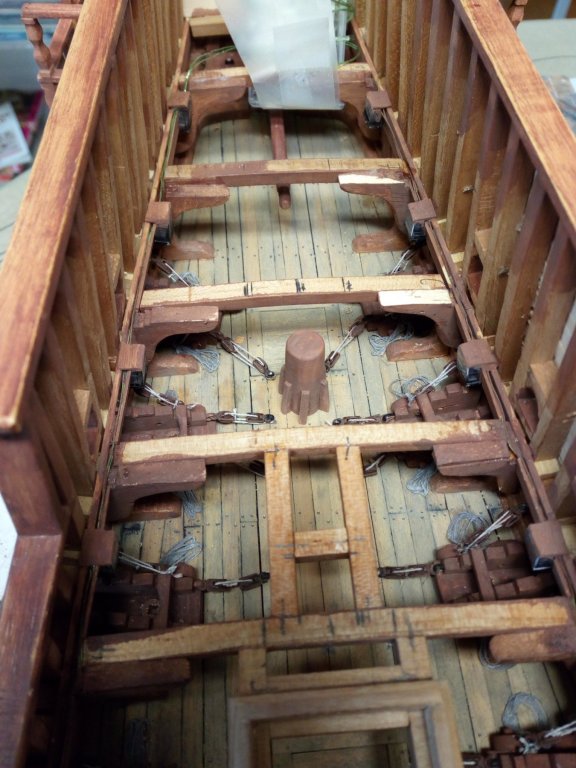
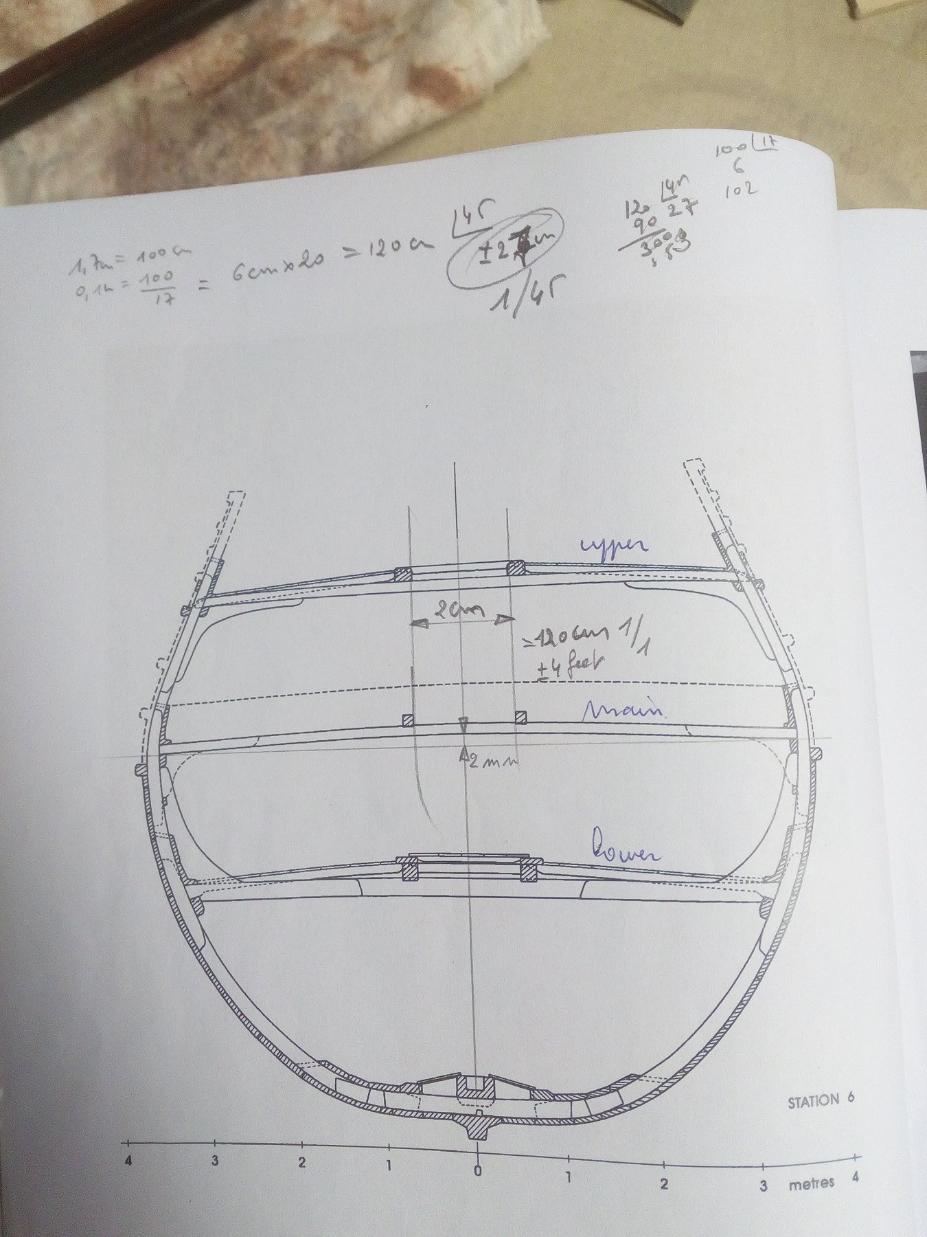
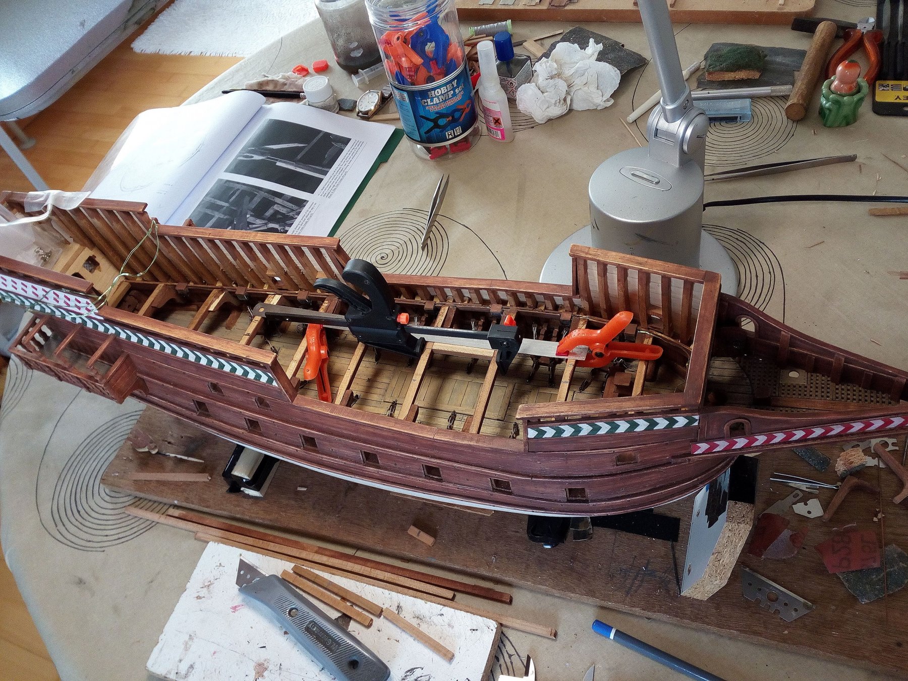
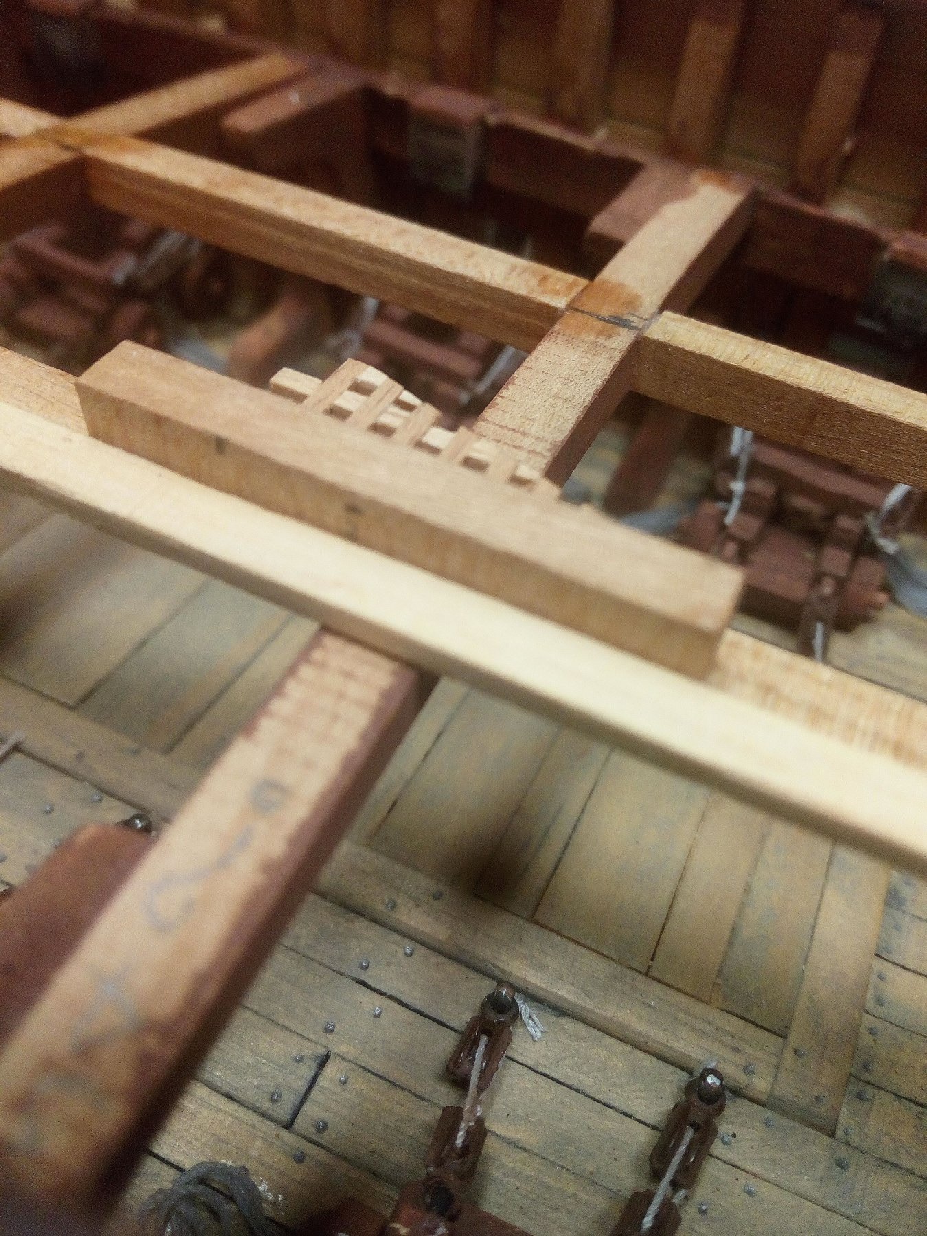
After installing the rudder are all deck beams in place. And i started with the holes for the hatches. The width is approximately 120 cm (about 4 feet) on scale 1/1
Work in progress
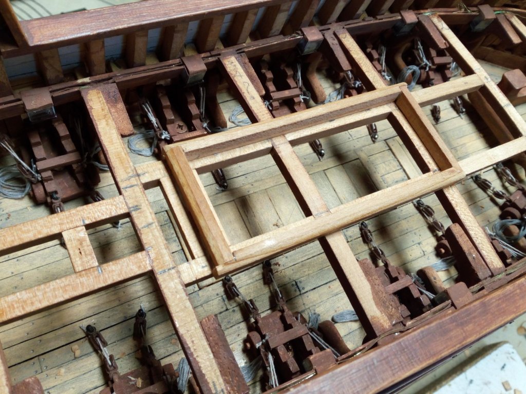
A first test to see what it will look like. The thickness of these deckplanks will not be visible later
I make it too thick, this will give extra strength to the deck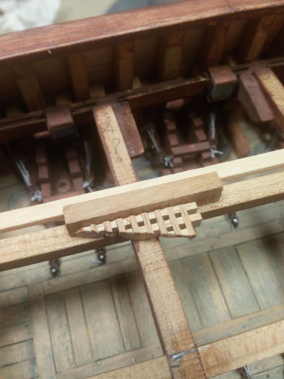

Further finishing, the deck beam in the center of the hatch will later be removed later on
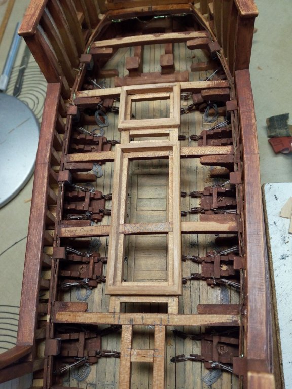
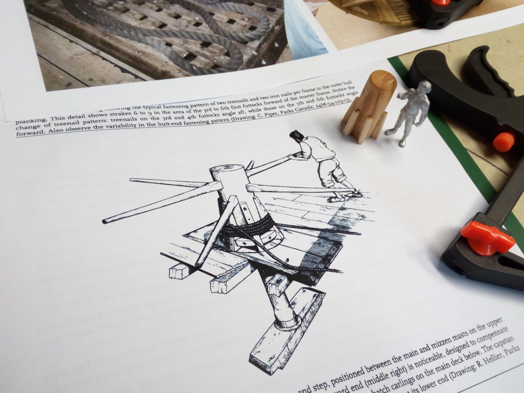
To be able to lift the anchor there must be a capstan on this deck.
The capstan is build very basic. And is placed at the only place where there is still enough room left .
Thanks for following


Santisima Trinidad by md1400cs – FINISHED - OcCre - 1/90 - cross-section - bashed
in - Kit build logs for subjects built from 1751 - 1800
Posted
As always, beautiful work Michael