

Baker
-
Posts
3,663 -
Joined
-
Last visited
Content Type
Profiles
Forums
Gallery
Events
Posts posted by Baker
-
-
G.L.
For the gun deck simple softwood.
Easily processed and will be almost not visible on the finished model.For all of the visible decks and planks of the hull.
Ramin wood.These are remnants of when we built our house 25 years ago.
I dont know the correct English word. But they are "plinten" (plinths,)( The finish plank between the wood floor and the wall)
The ramin currently being sold is very soft and does not look at what was sold 25 years ago.
I do not think the real ramin is still available.
For the upper frames and other parts : cherry wood.
From a cherry tree that is cut down two years ago.
-
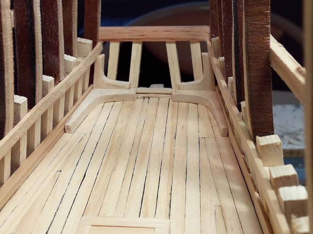
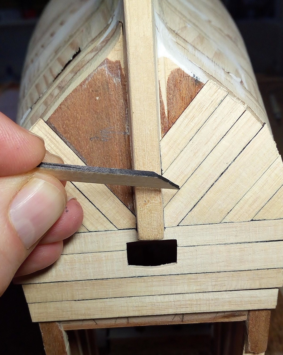
Planking the lower part of the transom
As can be seen, the planks are not equal in width.
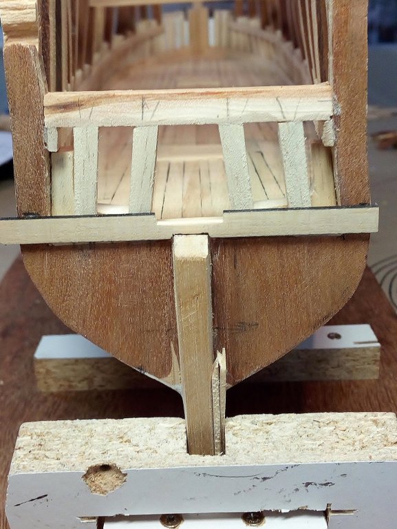
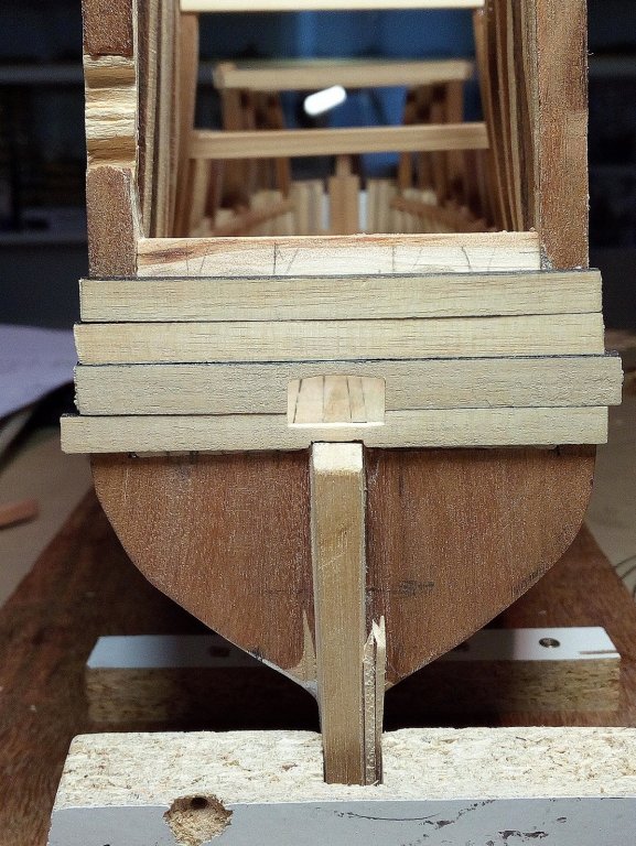
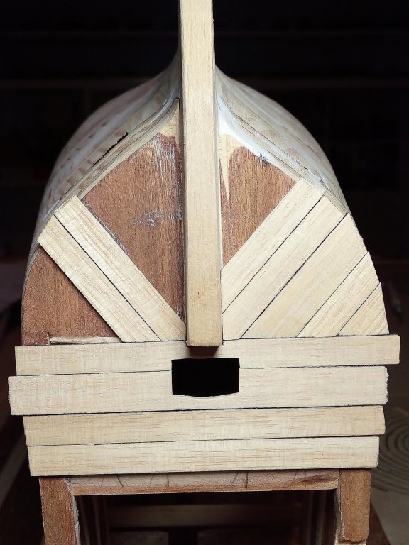
The side edges of Planks are blackened
And the lower planks are bent around the corner.
This was done for more strength at this part of the hull

This lower space has now been left open.
I will try to make these planks when the hull is planked.
Additional details are for later when the hull is planked
as always
thanks for watching, comments and likes
-
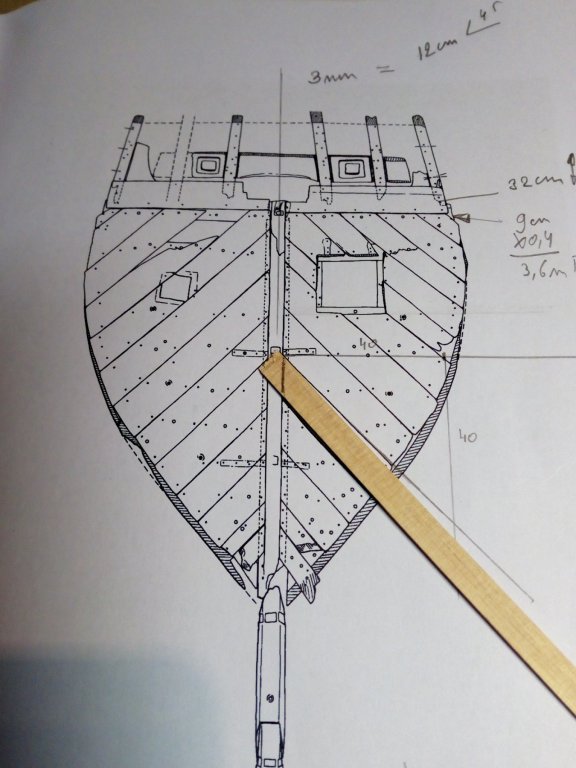
"frames" on he transom
When I started the construction of this model. Replicas of 16th century ships, built or under construction, were first used as an example to determine the thickness of the keel and stempost.
For some reason the keels and stempost on these ships are always very wide.
A Golden Hind in the 70ths

A Mayflower in progres
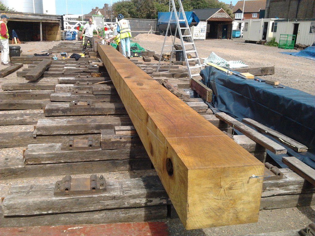
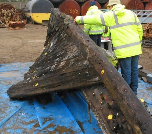
In contrast to the keel and stempost found at shipwrecks.
Gresham ship
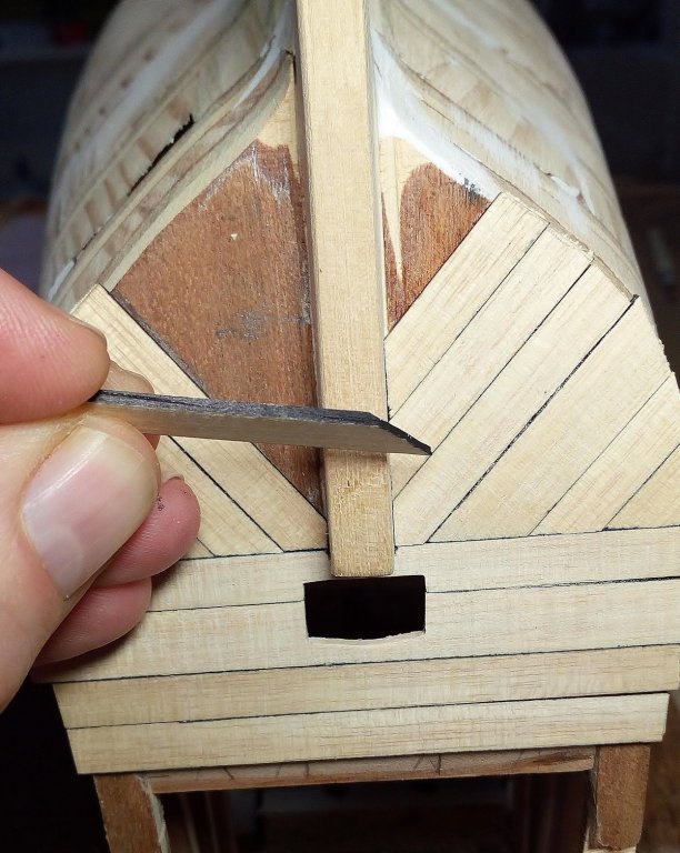
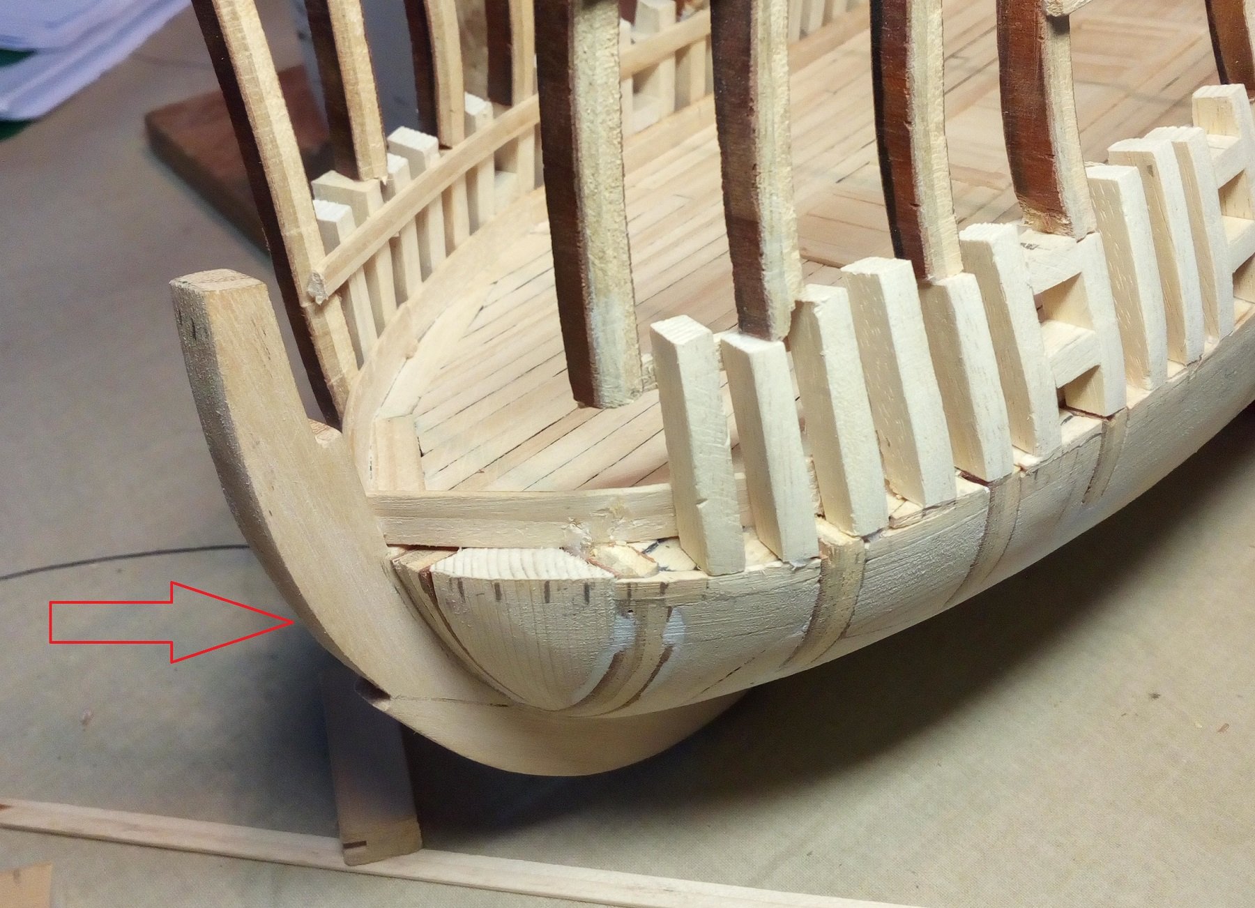
Therefore, stem, stern and keel are first made thinner 1 mm on both sides.
This gives a better view.

After planking of the hull they will be further sanded into their final shape.
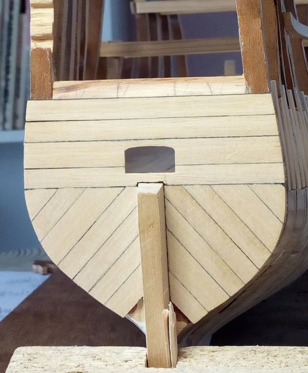
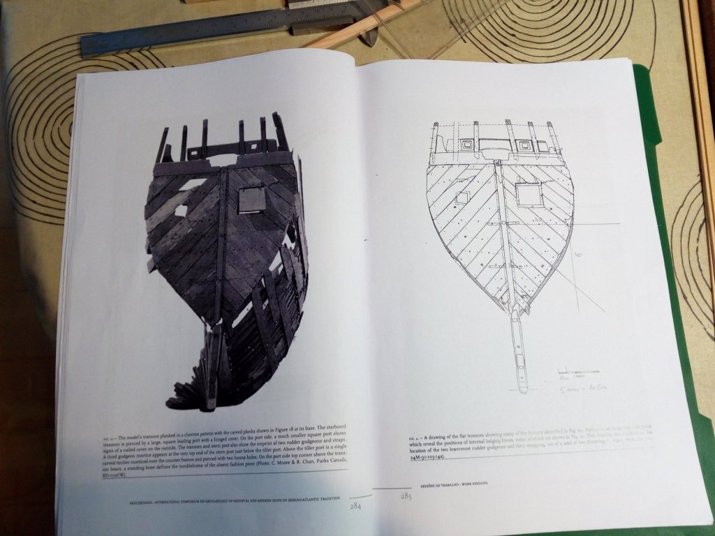
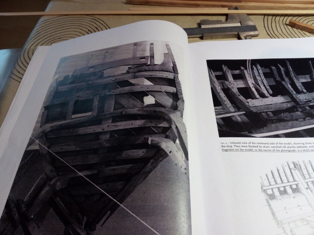
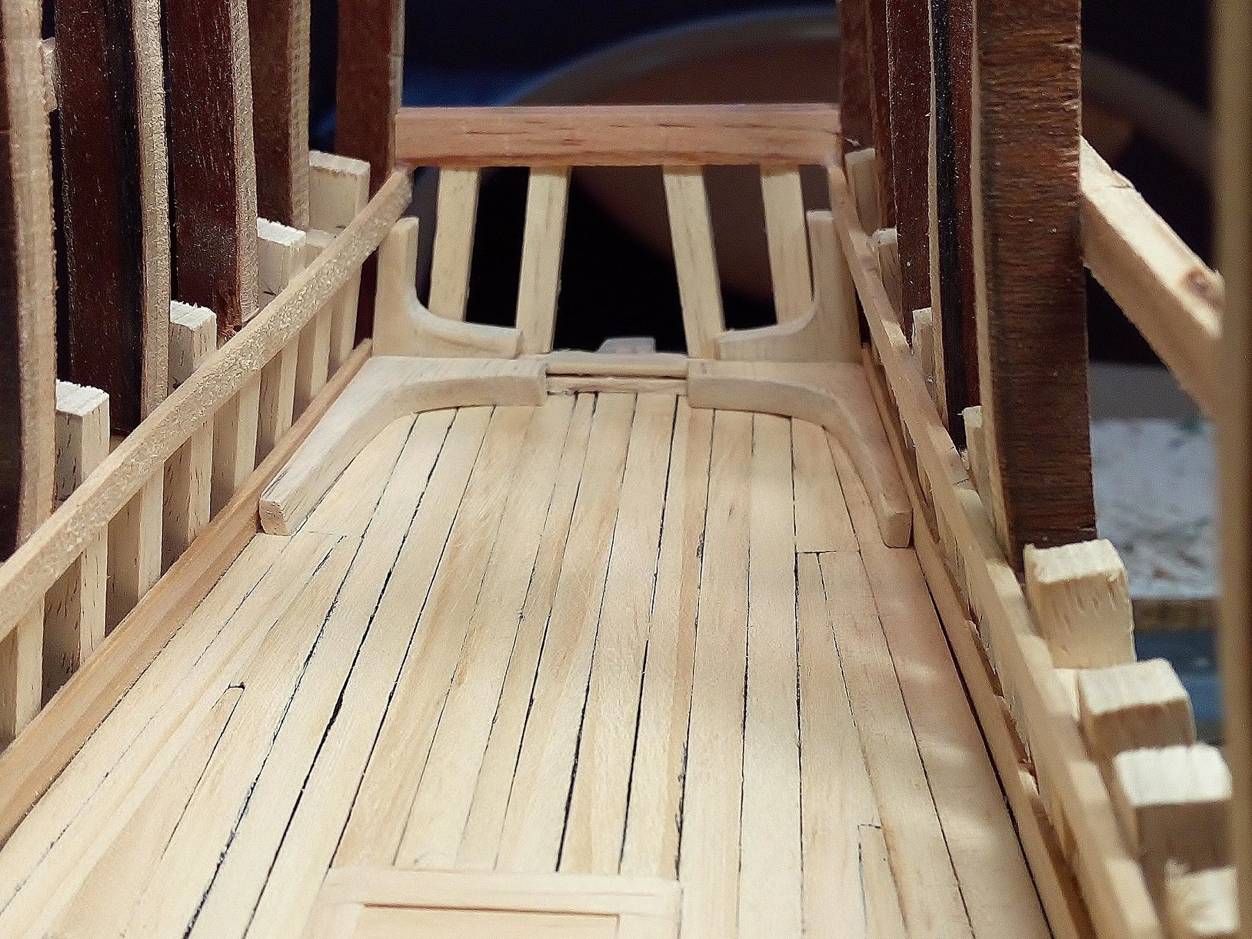
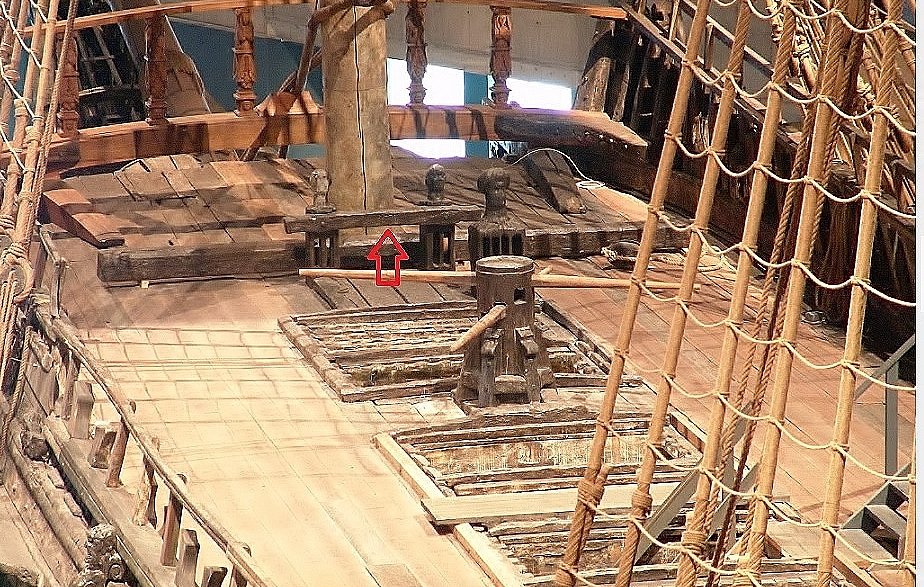
Beams are placed to attach the planking on the transom
As well as 2 standing knees and 2 lodging knees.

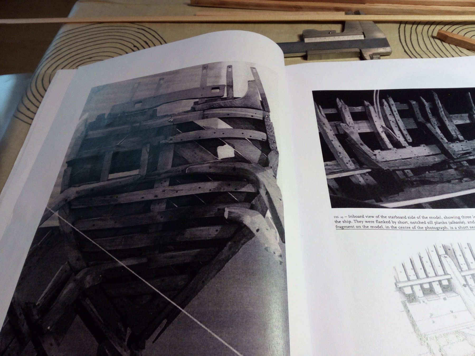
An example is the transom of a 16th century Spanish galleon. Found in Red Bay.
Maybe not entirely correct. But perhaps the only transom from this time that survived
- Louie da fly, BETAQDAVE, archjofo and 3 others
-
 6
6
-
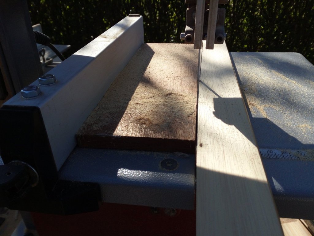
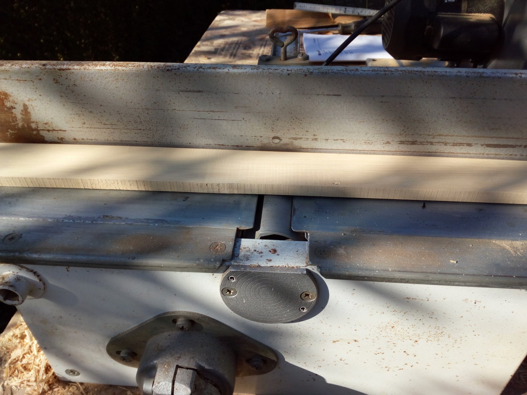
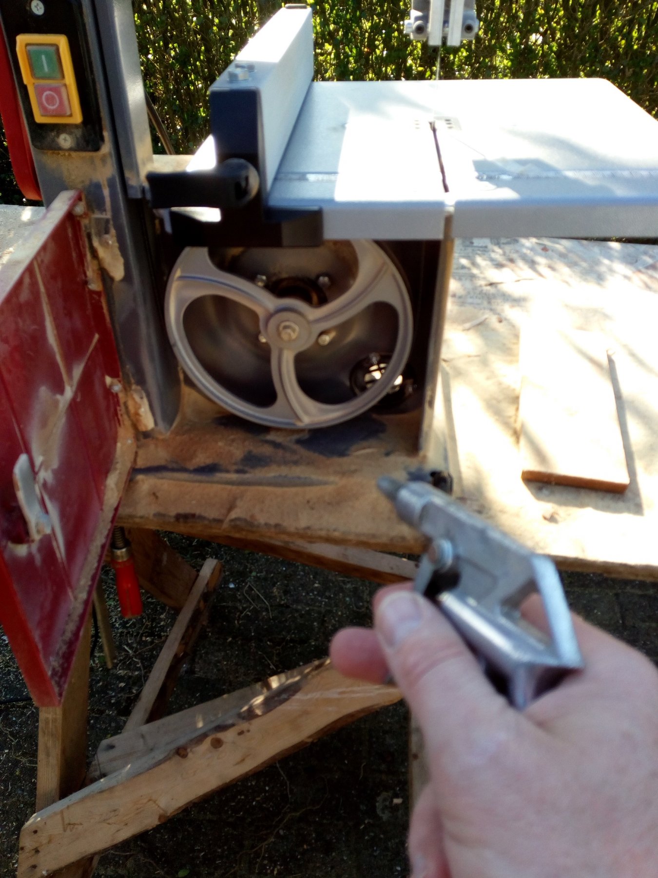
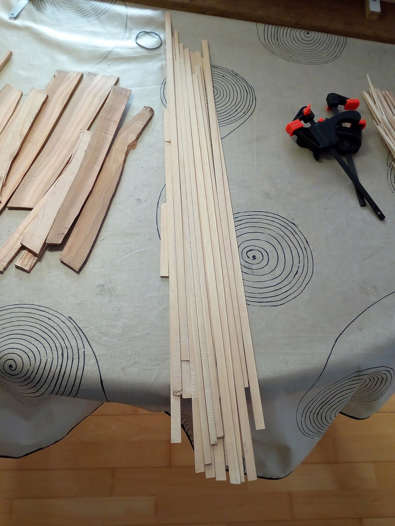
I'm out of wood now.
So, first saw timber for planks and beams.
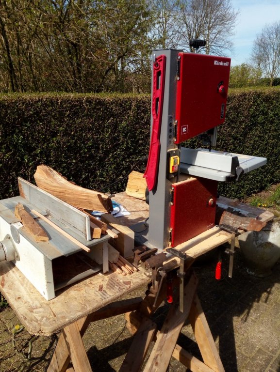
Of cherry wood pieces are made for the upper frames and beams.
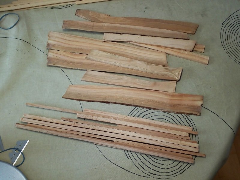
Of the( real) ramin planks are sawn.

Cleaning

A first "batch" is ready.

And,
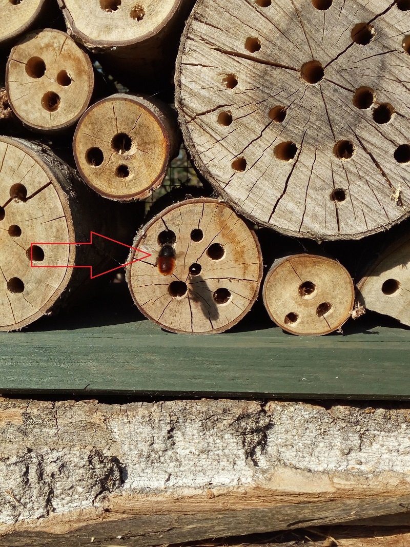
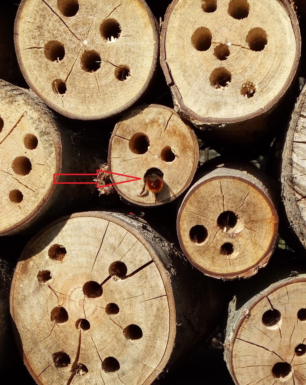
(Has nothing to do with ships. But nature is beautiful
") )
)
My bee hotel, made last year and see post N° 6, welcomes its first guests.
https://en.wikipedia.org/wiki/Insect_hotel


-
Hallo,
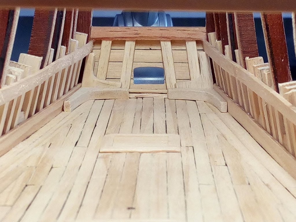
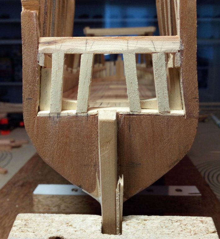
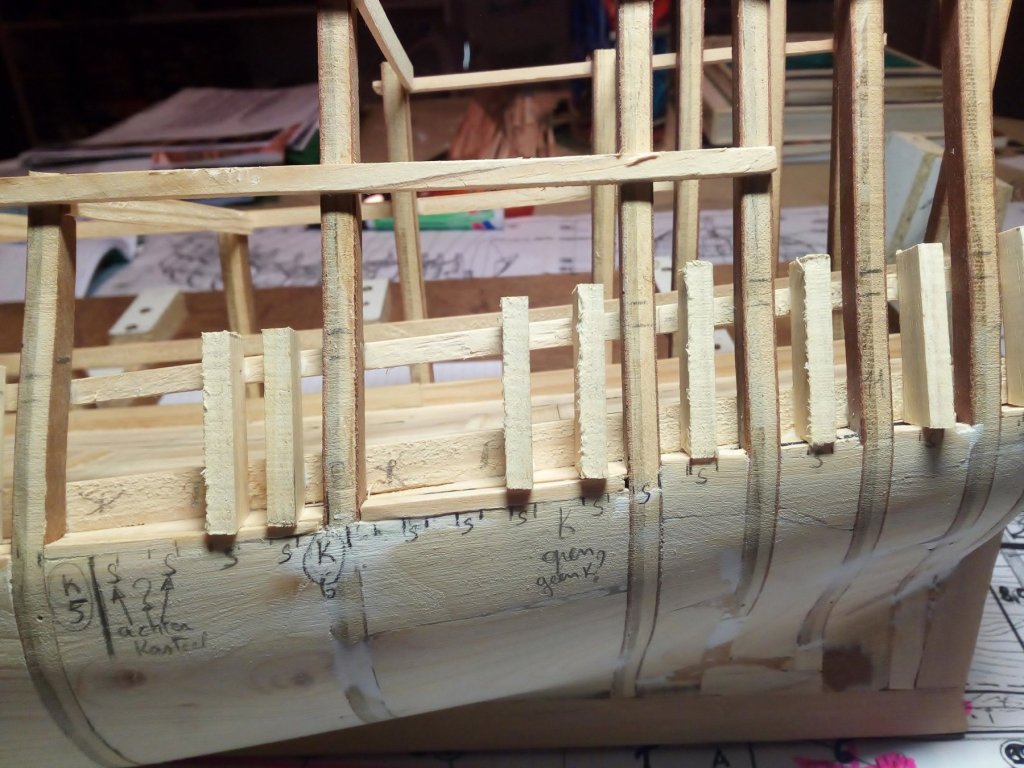
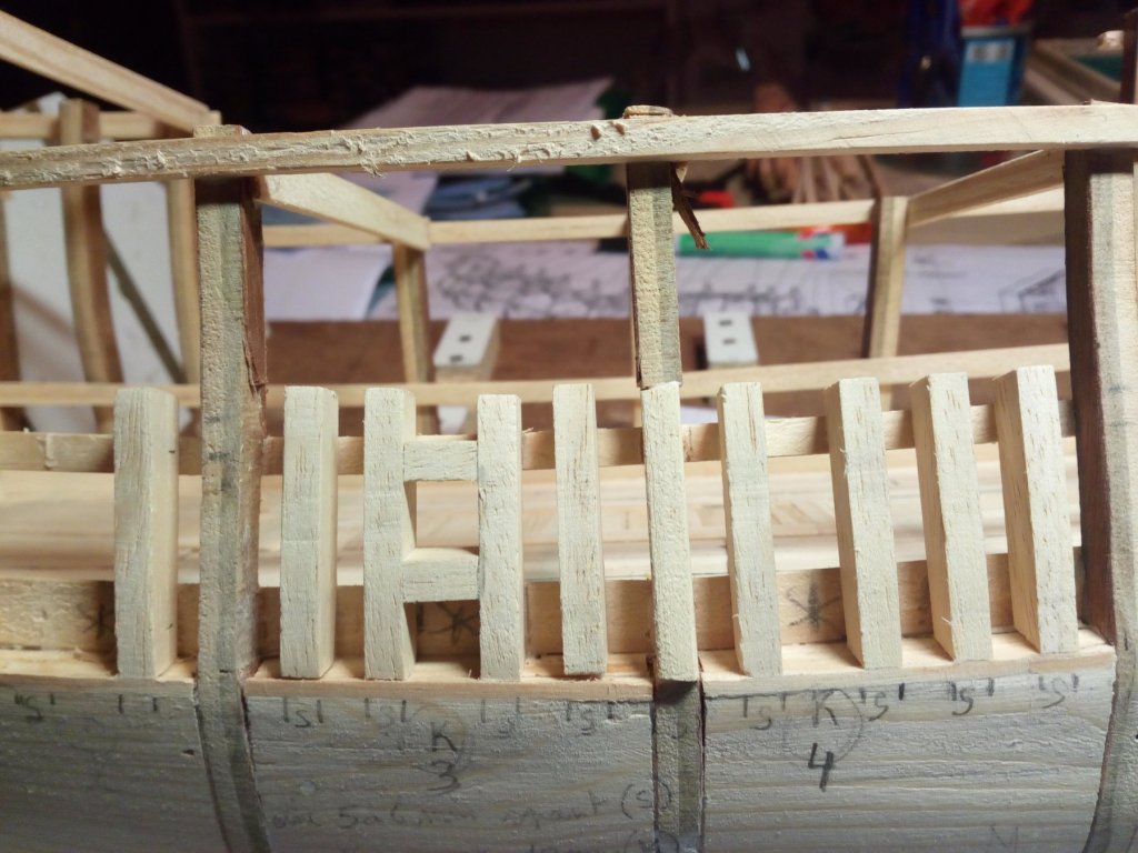
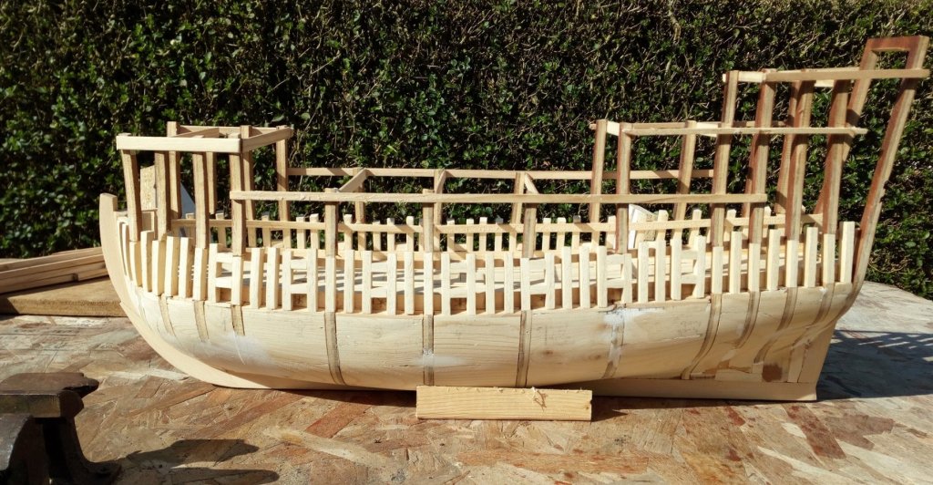
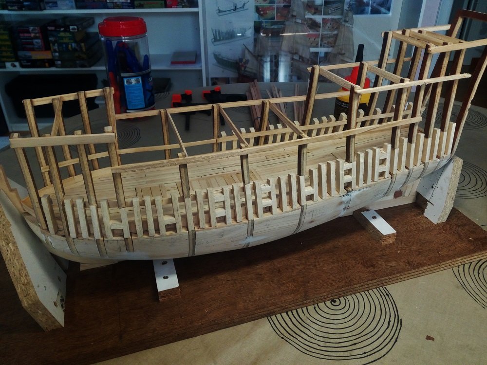
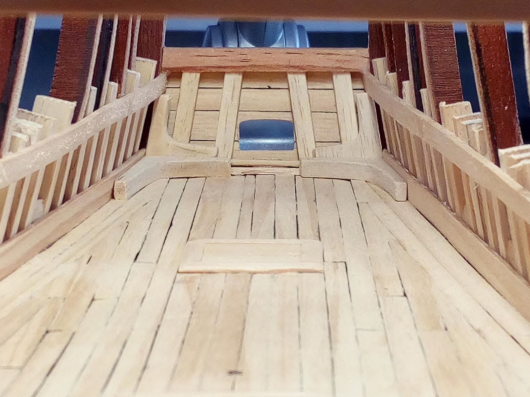
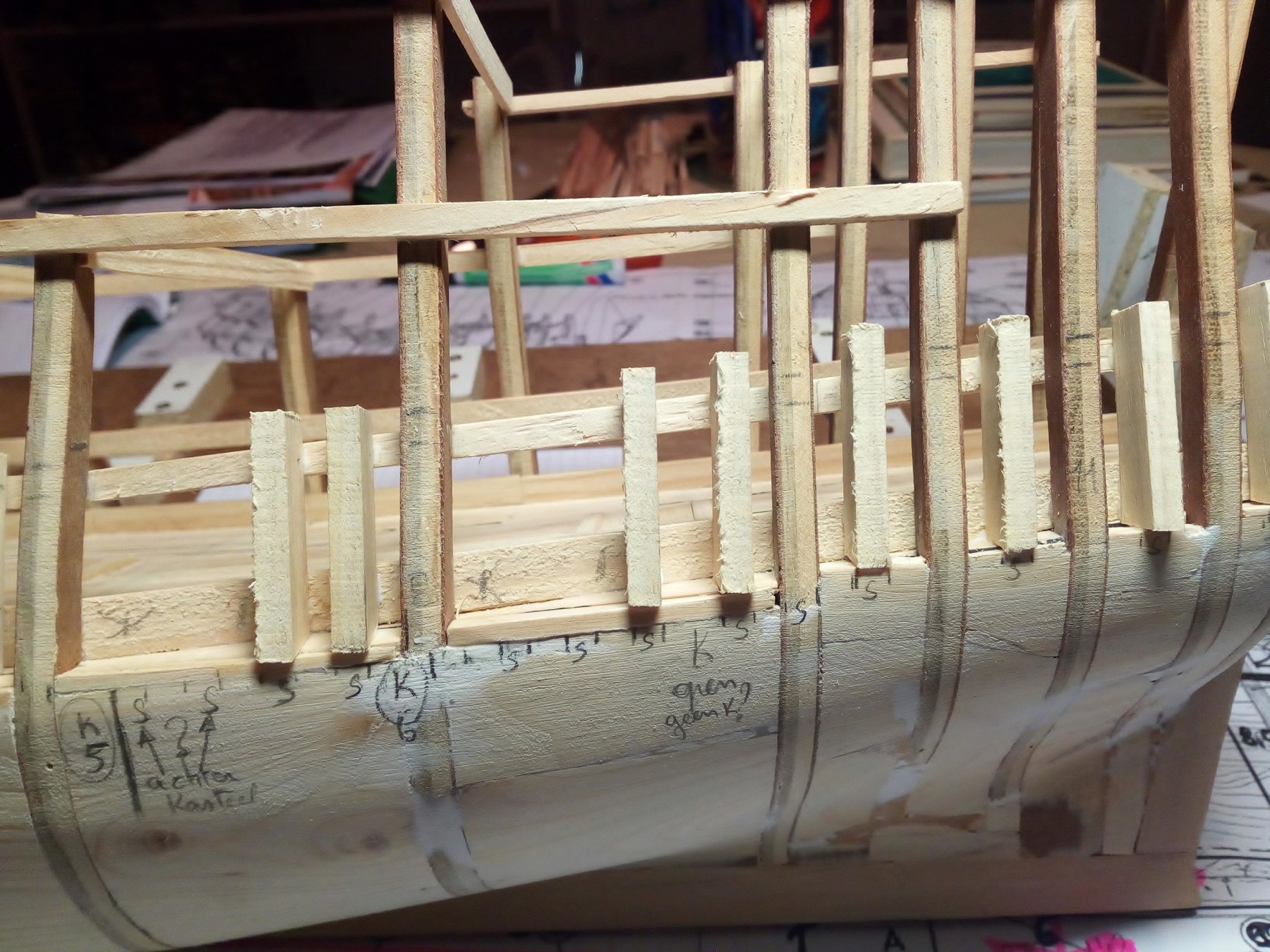
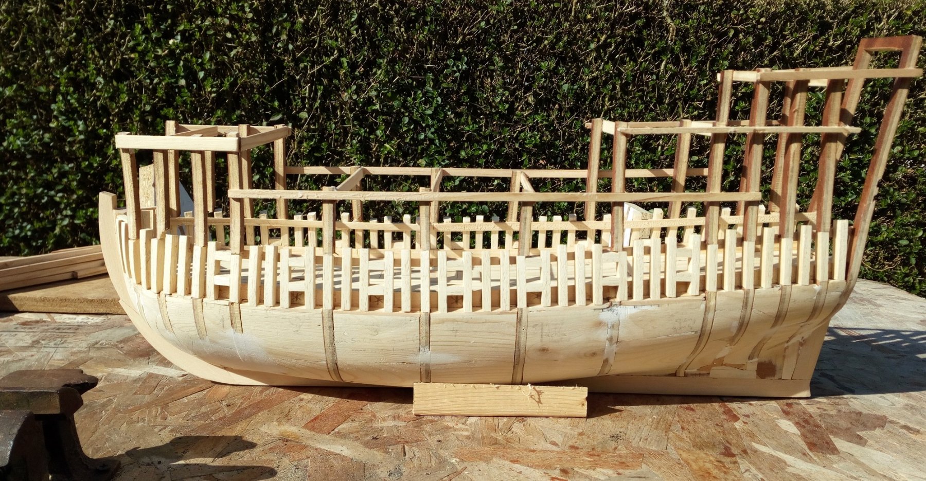
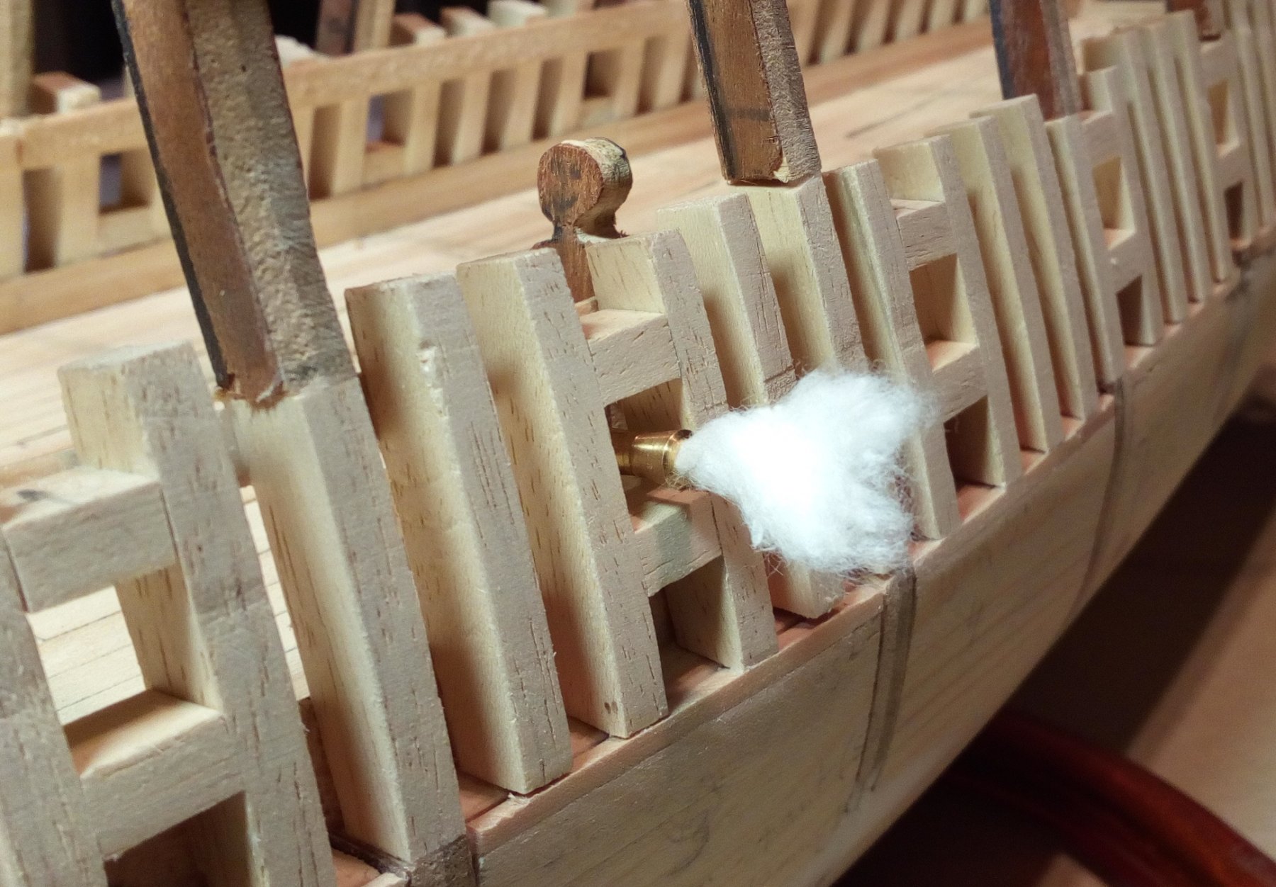
Frames (futtocks) and gunports .
The aim is to have a better detailing of the gun deck when looking through the gunports.
If needed, there may be applied more detail later
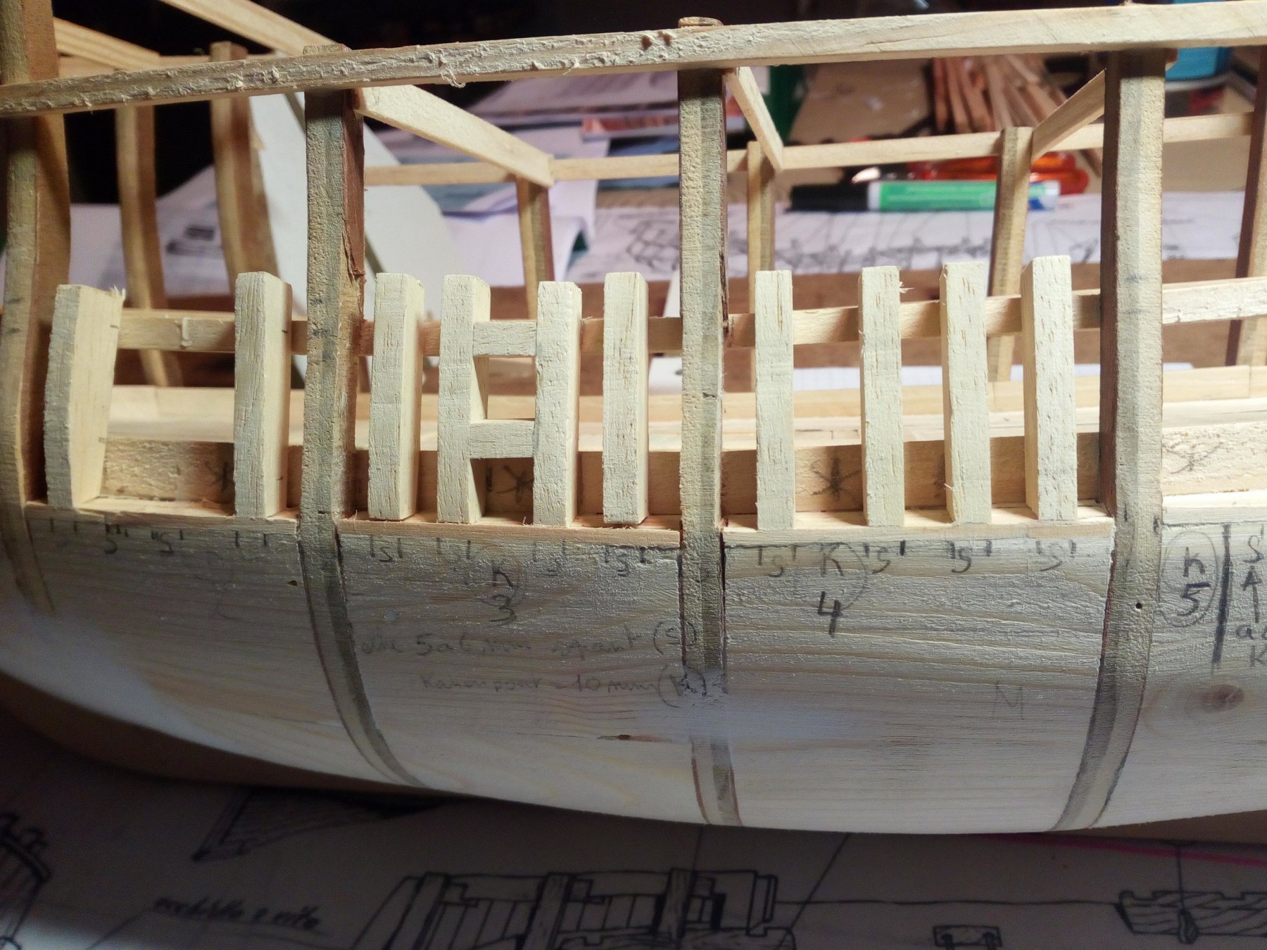
It seems that this time periode the inside of the frames were not fully planked.
Frames (futtocks) are finely finished only where they have to fit together.
The other sides are rough sawn or cut out with an ax.
But on a finished model this seems sloppy.
Therefore, my futtocks are sawn and sanded
And,
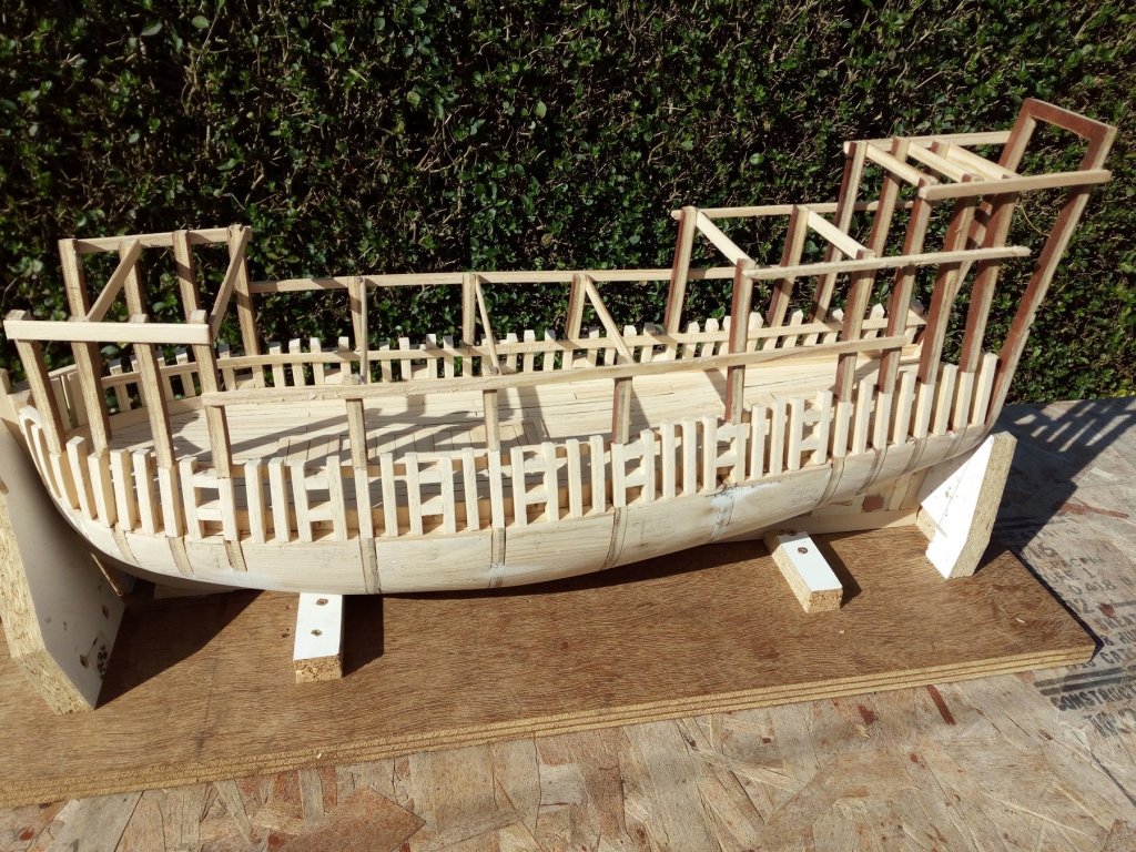
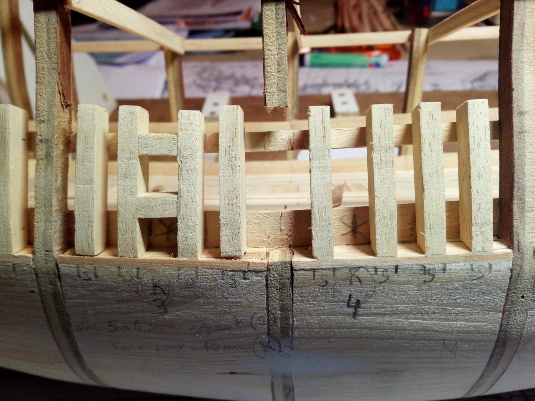
It is quite possible that the frames were farther spaced. Or not.
Maybe the gun ports were smaller or larger on some ships.
And maybe some ships were planked inside.
Who knows.
All of this will be barely visible when the upperdecks are placed
More information is available via this link.
http://www.wessexarch.co.uk/files/PMA41.2Auer-Firth.pdf
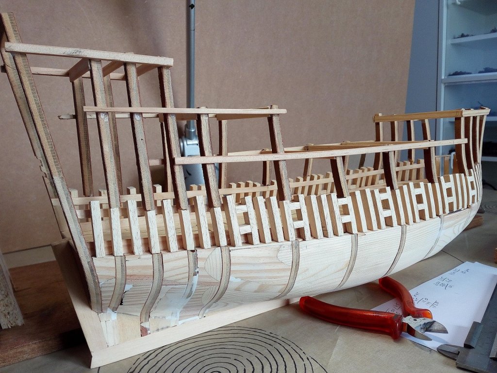
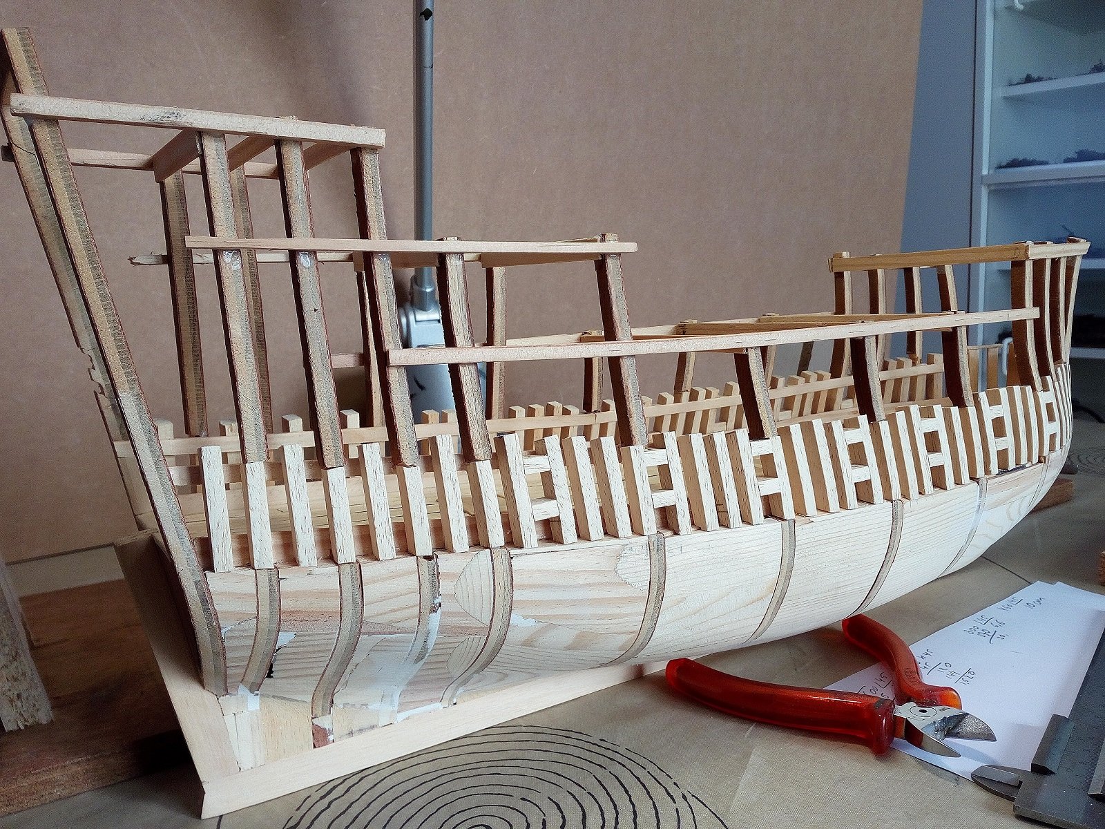
First it is determined where the frames and gun ports should be
Then between the plywood frames solid pieces wood are glued.
Softwood “ramin” was used here. Saws and sands easily.
There is a remarkable difference in the Ramin pieces that are on my attic for 25 years (very hard)
And "ramin" which I bought last year in the wood shop (very soft).
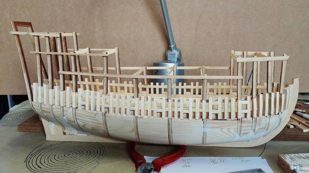
The frames are then equal sanded.
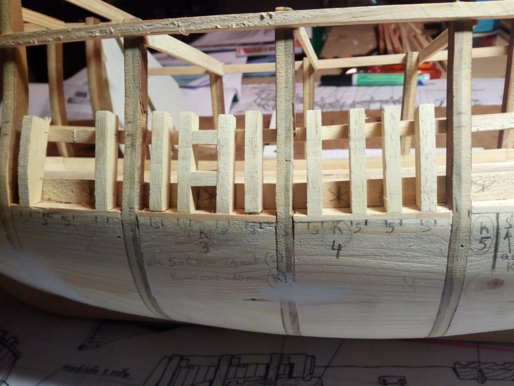
The plywood frame is removed and replaced with a solid piece of wood and sanded.

Work in progress
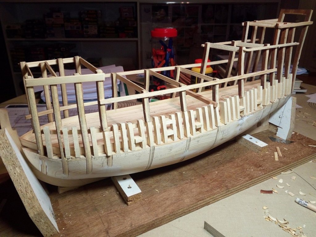
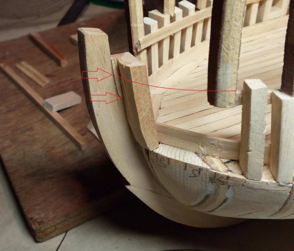
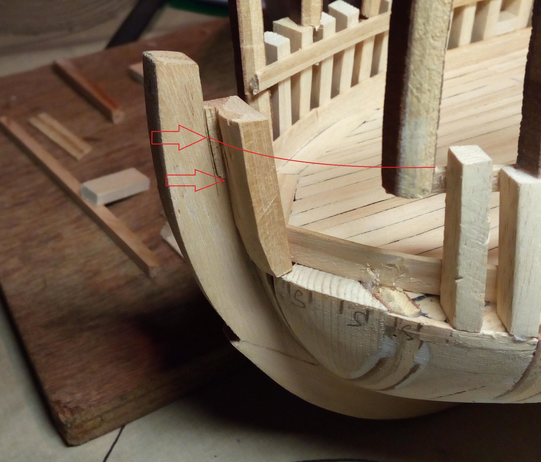
A piece of the bow is removed.
In a later stage, an adjusted piece will be placed back

This should be higher. Otherwise, I'm not at the same height with my deck.
The seam will be covered by the planking of the hull.
Finish.
My "employee" just had to celebrate this.
From the partsbox he made this gun.
He don’t understands that the wheels of a British crusader tank really do not belong under a medieval cannon.
Installing the cannon
 .
.
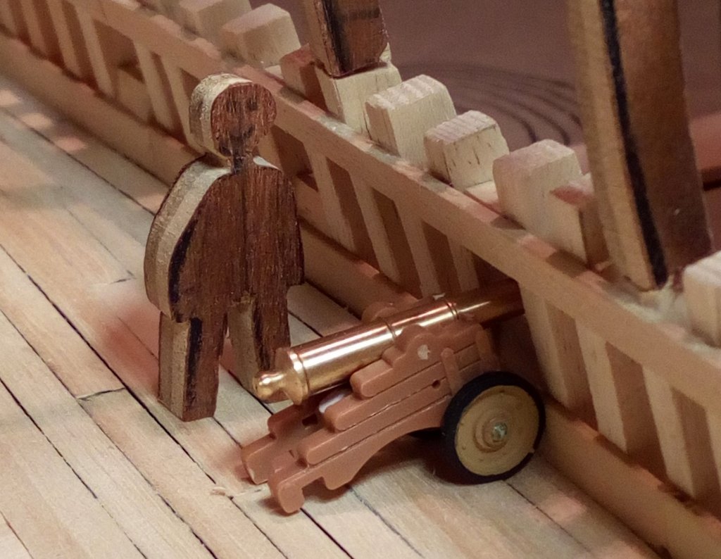
Fire.

Test succeeded.
Everyone happy
.
LOL
-
I'm glad I could help.
Another BB Vasa without the pinoles
")
- zoly99sask, md1400cs, coxswain and 4 others
-
7
-
-
Thanks for the positive comments.
Have you used this approach before?
Scott,
No. This was my very first lantern on my first ship.
It is made in plastic because I have most experience with this material from my military modeling
But I remember this advice when I make a lantern for my Golden Hind.
-
Michael,
I did fair the bulkheads before installing the filler blocks.
Since I did not have good drawings. I had to draw my own bulckheads (frames)
These filler blocks have saved my model.
For me it is like the first planking on the hull. But with more space for sanding away any errors
- Canute, mtaylor, thibaultron and 1 other
-
4
-
If I understand it correctly (i hope), the question is about filler blocks.
This way I made my blocks.
Be careful with the grinder. Sanding goes quickly.- thibaultron, Canute and mtaylor
-
3
-
Thanks for the positive comments and likes.
In English and Flemish.
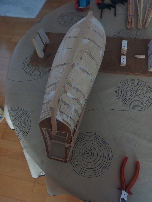
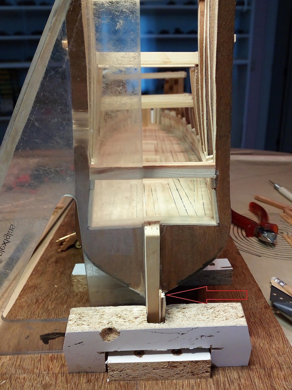
Just seen on the picture
On the stern there is still an error of a few mm.
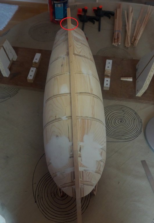
Building a hull without proper drawings and with my limited experience is not easy
But, sometime we will get it to the finish with this model (in a few years....)
-
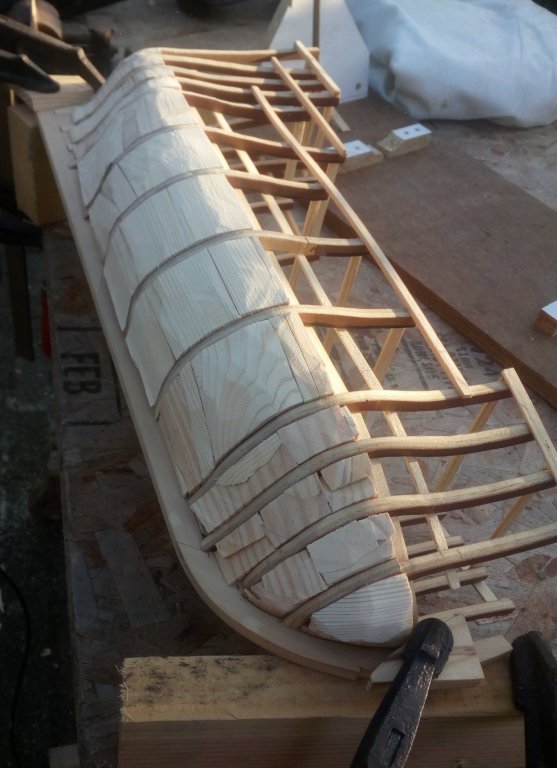
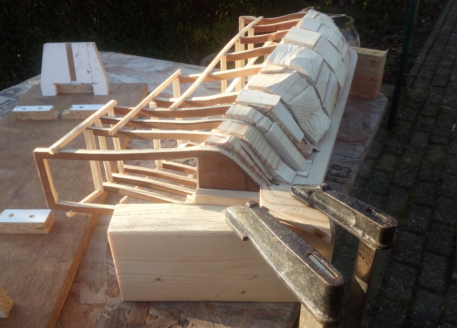
Hallo,
The filler blocks are placed on the starboard side.
Because sanding with the sanding machine is faster the blocks are not made in advance in to the proper shape.
This is now probably the most ugly hull ever shown MSW…..

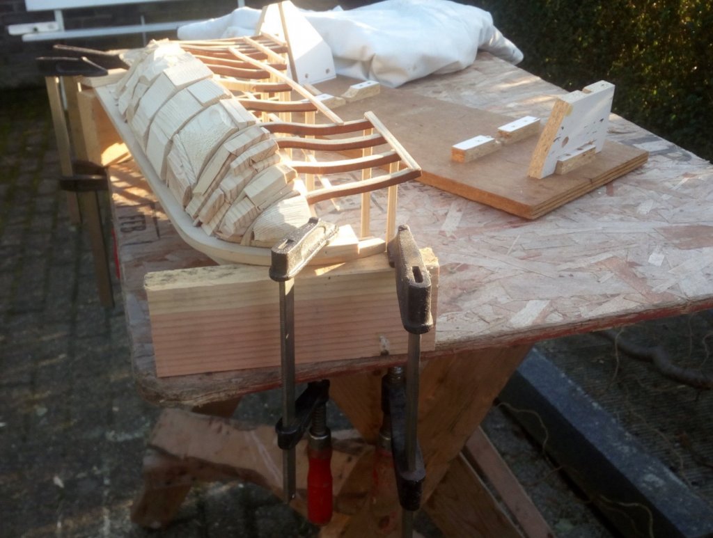
A few minutes of sanding and the shape is already better.
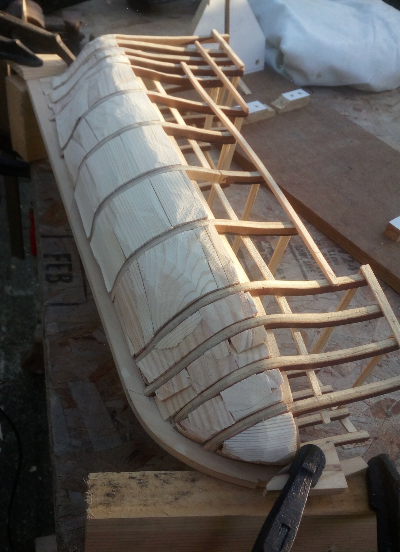
If you want to do this in the same way
Do this outside. This makes a lot of dust ....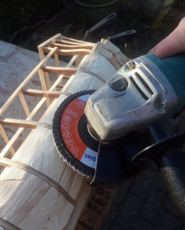
Now further filling and sanding until the desired shape has been achieved.
The lower part of the hull is ready for planking.
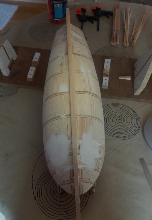
My first goal was to try to build a hull that has probably the right shape
Below the waterline it looks to be in order
next update : frames and gunports on the cannondeck
- Tadeusz43, zoly99sask, hexnut and 11 others
-
14
-
-
Good luck with the small jobs
Do not you think this is a dangerous place to put a ship model (even temporarily.)
Hopefully it does not fall.
That would be really pityIn dutch :
Dat zou zeer, zeer jammer zijn.
-
Thank you for restart this buildlog.
I follow
- mtaylor and Blue Ensign
-
2
-
I have to now only focused on English shipbuilding late 16th century (for my Golden Hind).
Even the early 16th century building method looks to be different from this.
perhaps there is no general correct answer to this question.
What type of ship?
What time period?
which nation?
Maybe even on which shipyard the ship is build?Each time period and country apparently had its own rules and habits.
-
- thibaultron, jud, druxey and 1 other
-
4
-
Lorne,
I will never use them.
So you can have these parts.Shipping costs will be your biggest expense
Send me a message where you live (or just which country you live).
Then I can see what the price will be.You can then decide whether you still want them or not.
Groetjes
Greetings
- Ondras71, mtaylor, chris watton and 1 other
-
4
-
-
-
-
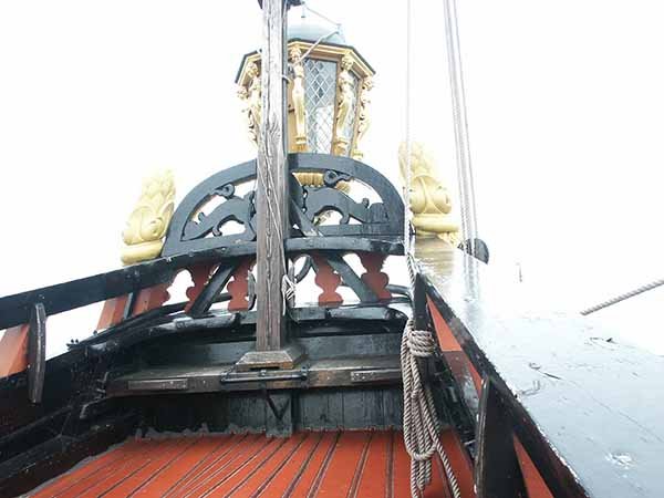
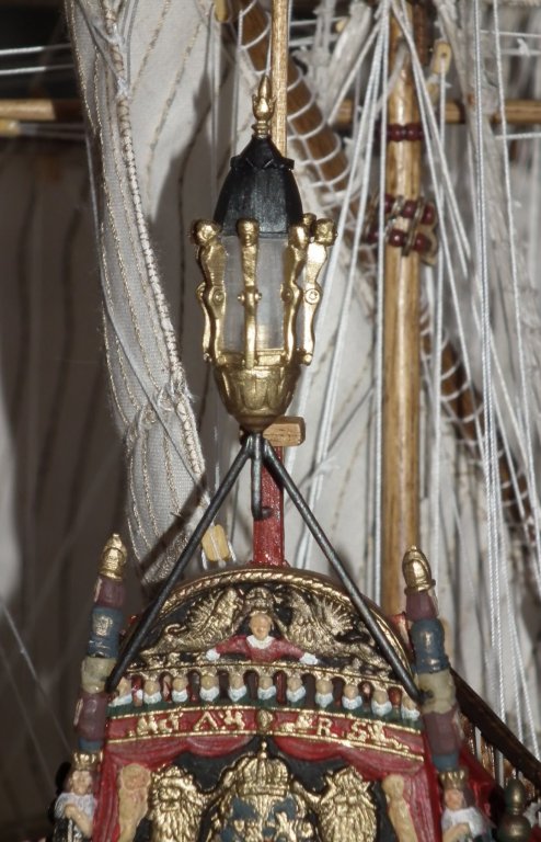
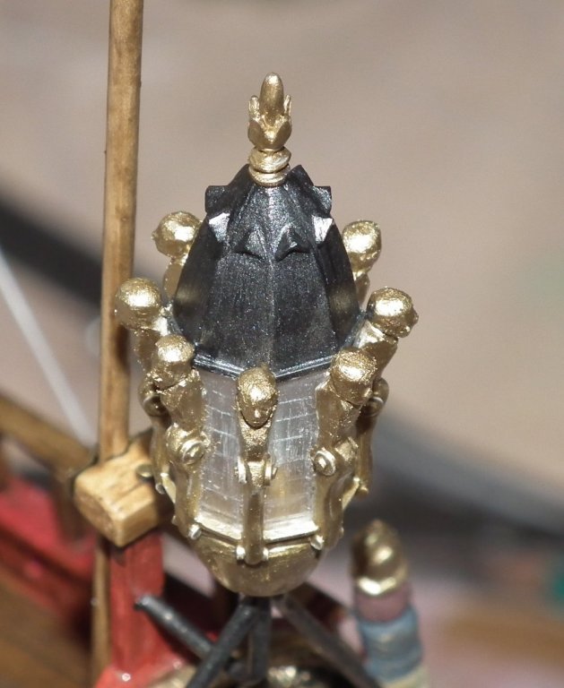
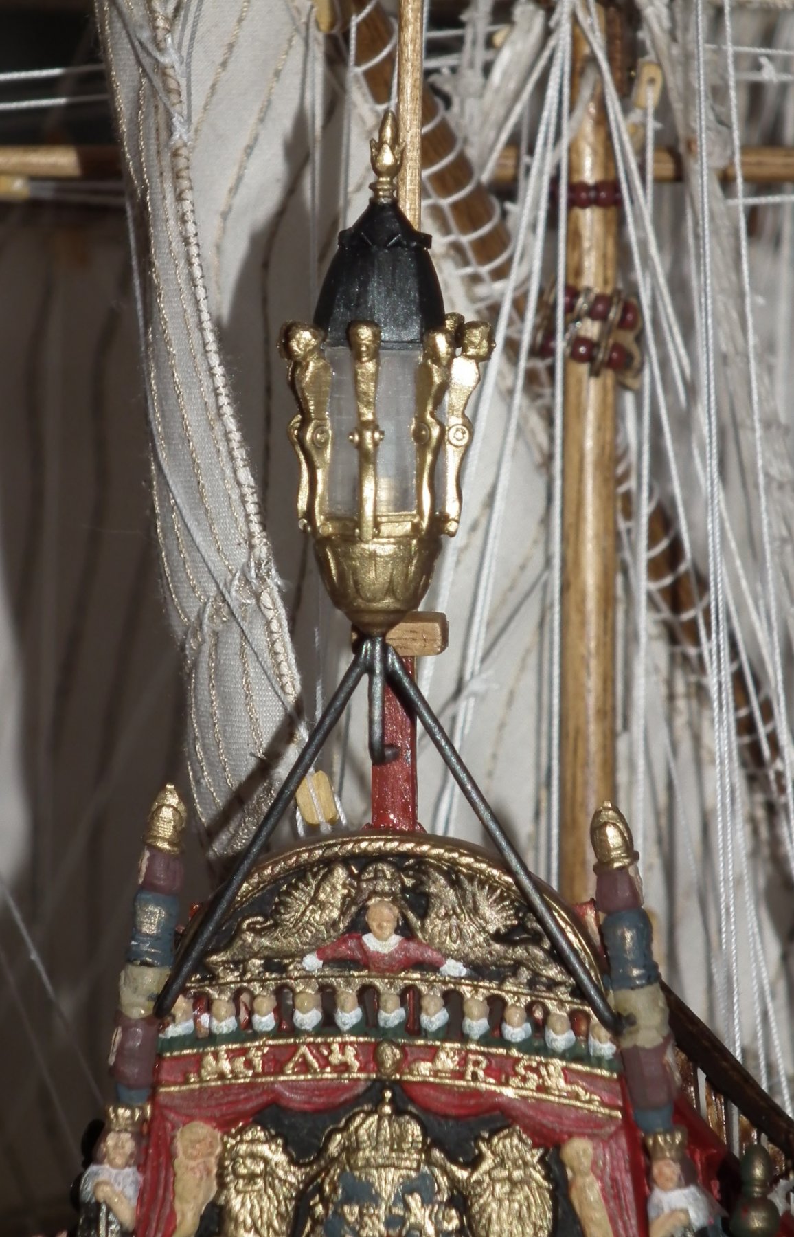
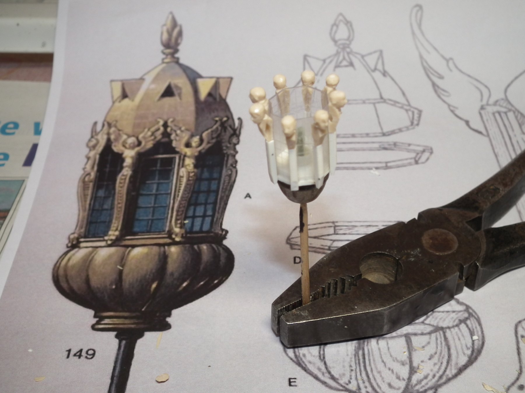
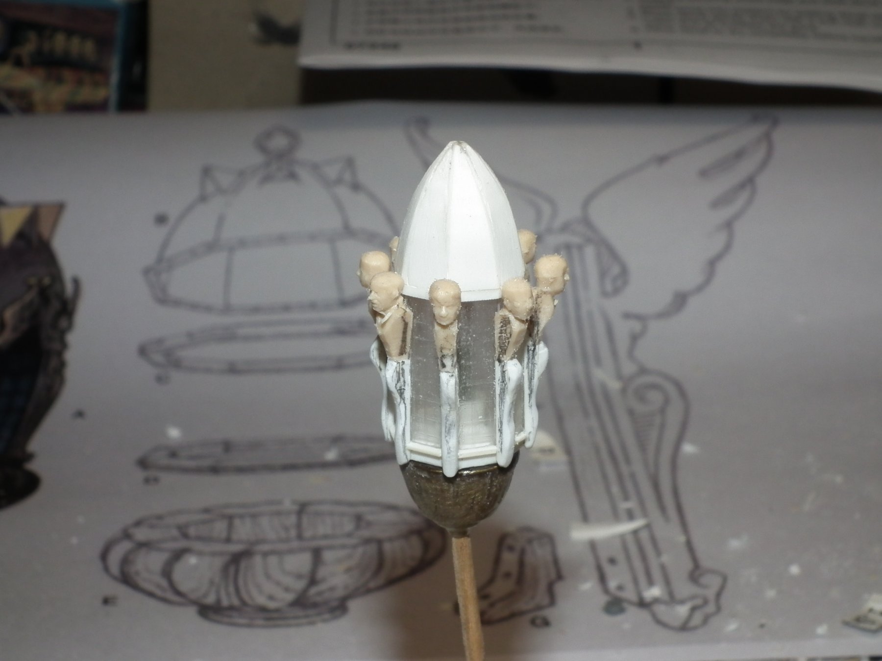
The making of an early 17th century ship lantern
writing English texts is not my best side.
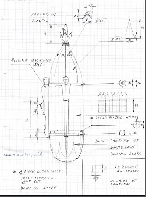
I hope that the photographs and the drawings are sufficient.
Here's the method of how I made my lantern for my Wasa Billing Boats.
A lantern of this type is also found on the Batavia replica.
I have attached a pdf with a drawing
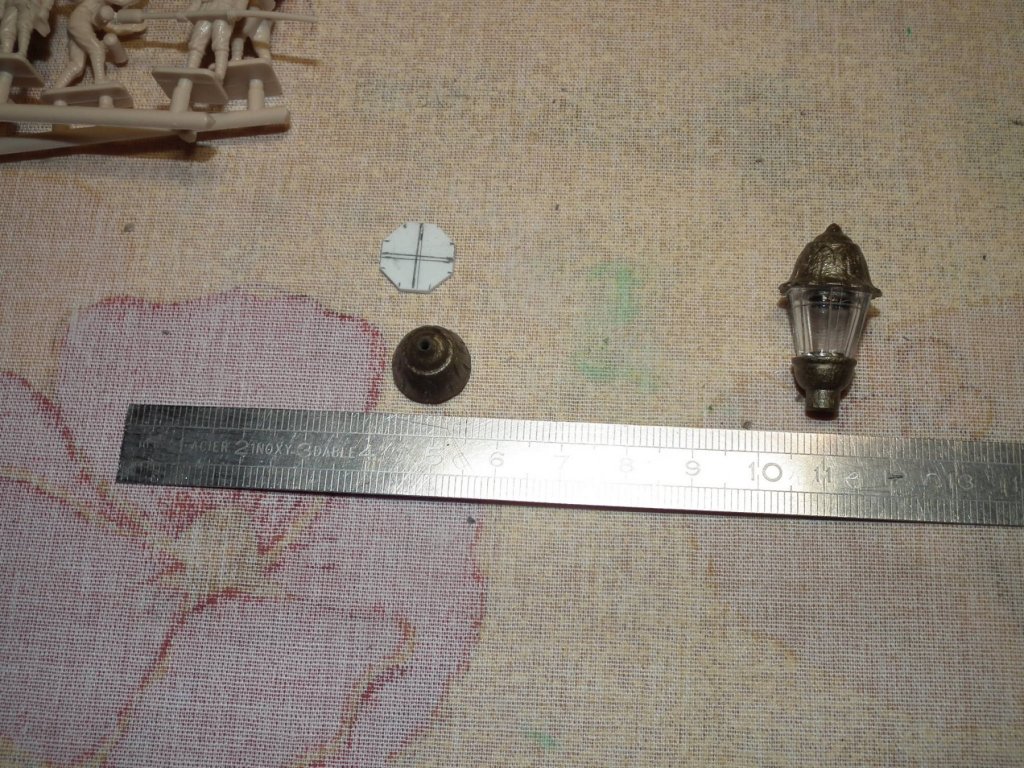
Dimensions are in mm (1 millimeter = 0.0393700787 inches)
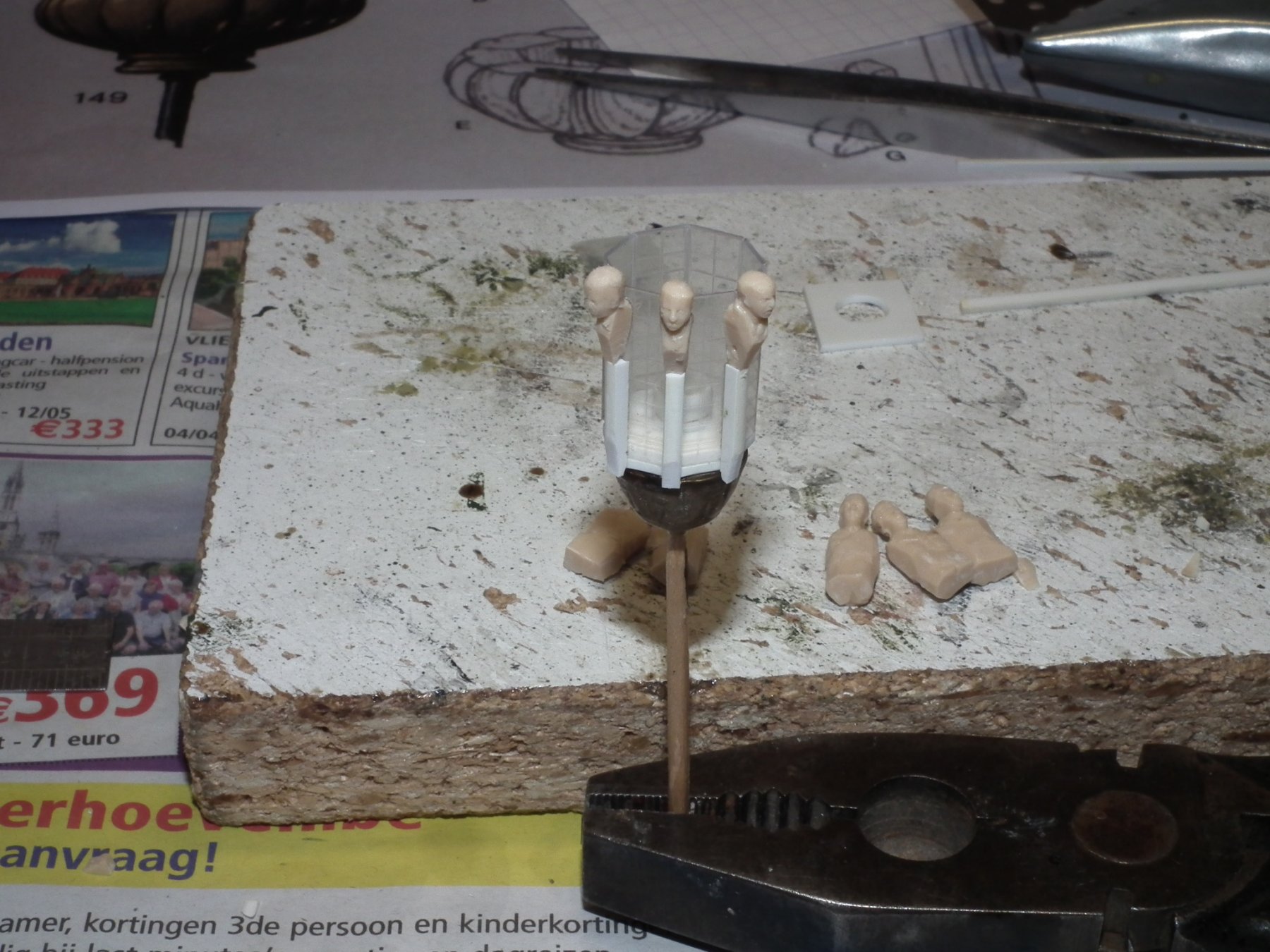
(Extra small details in plastic strip are applied on the lantern)
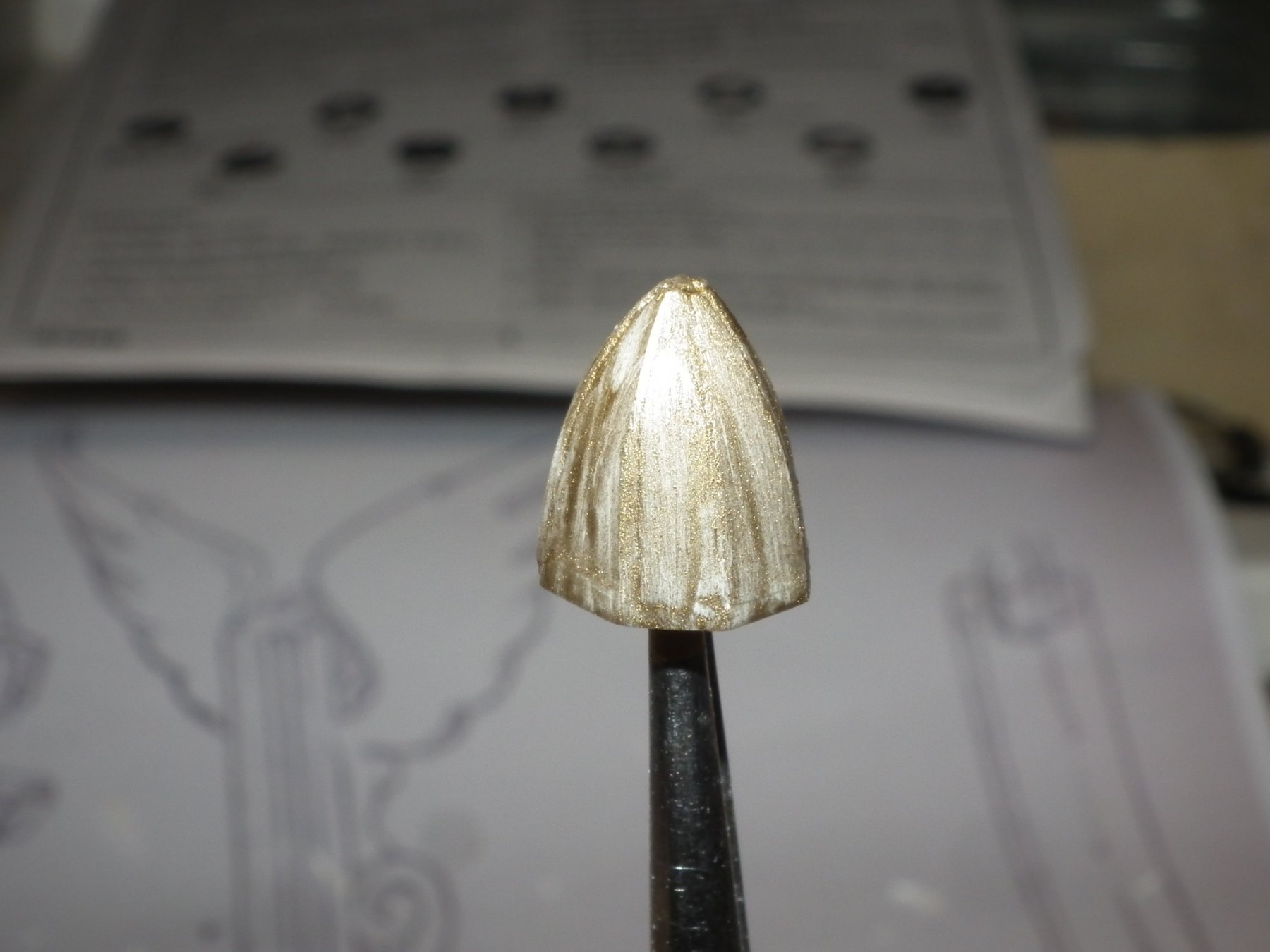
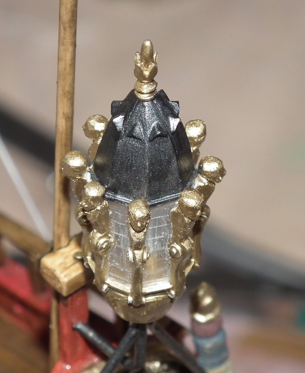
Painting is gold and gun metal)
The base came from lantern From Billing Boats
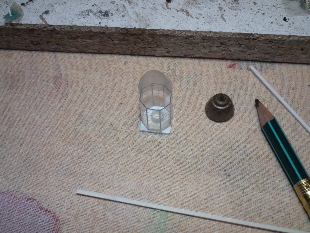

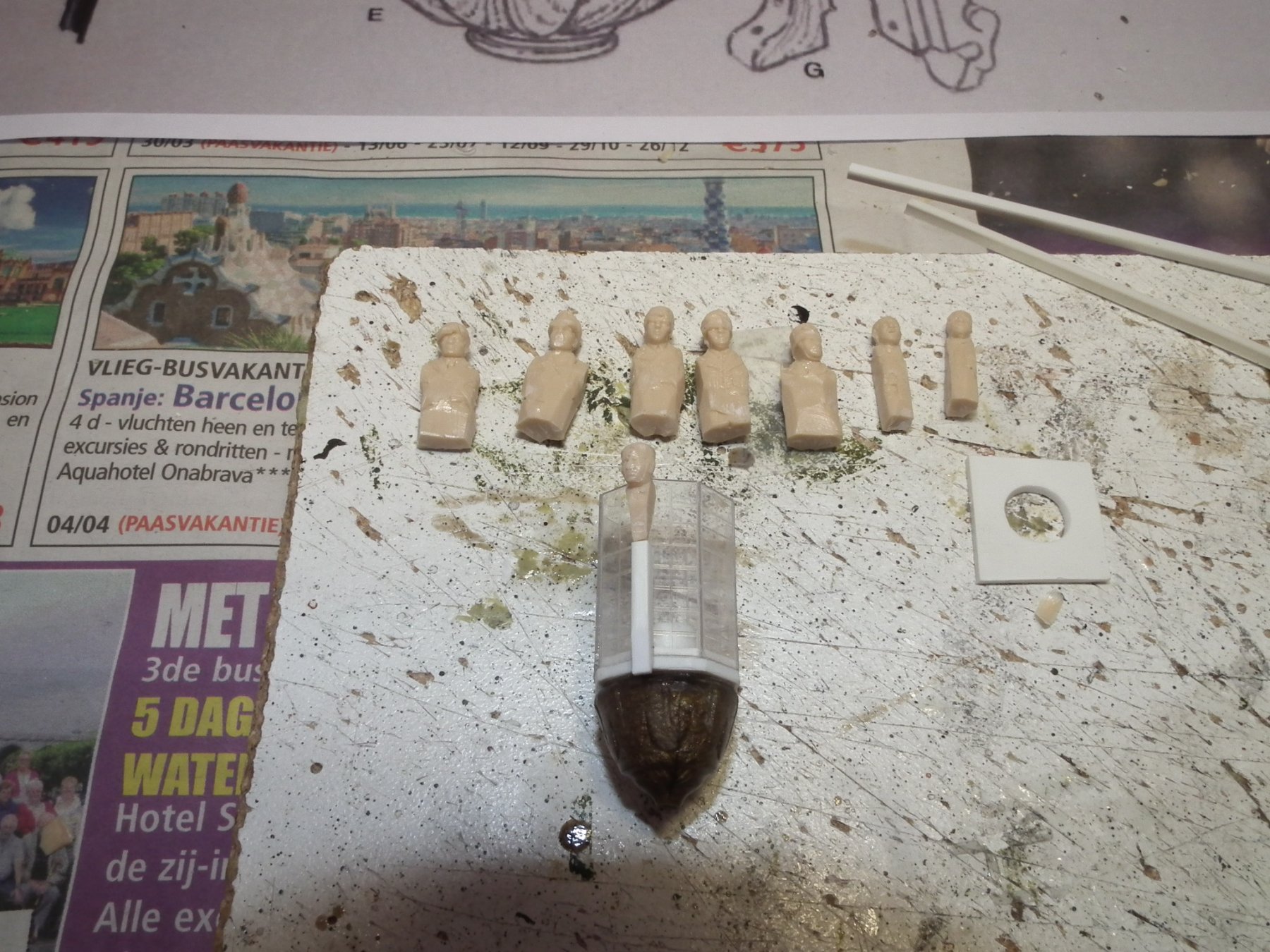
eight volunteers from the 1/72 parts box
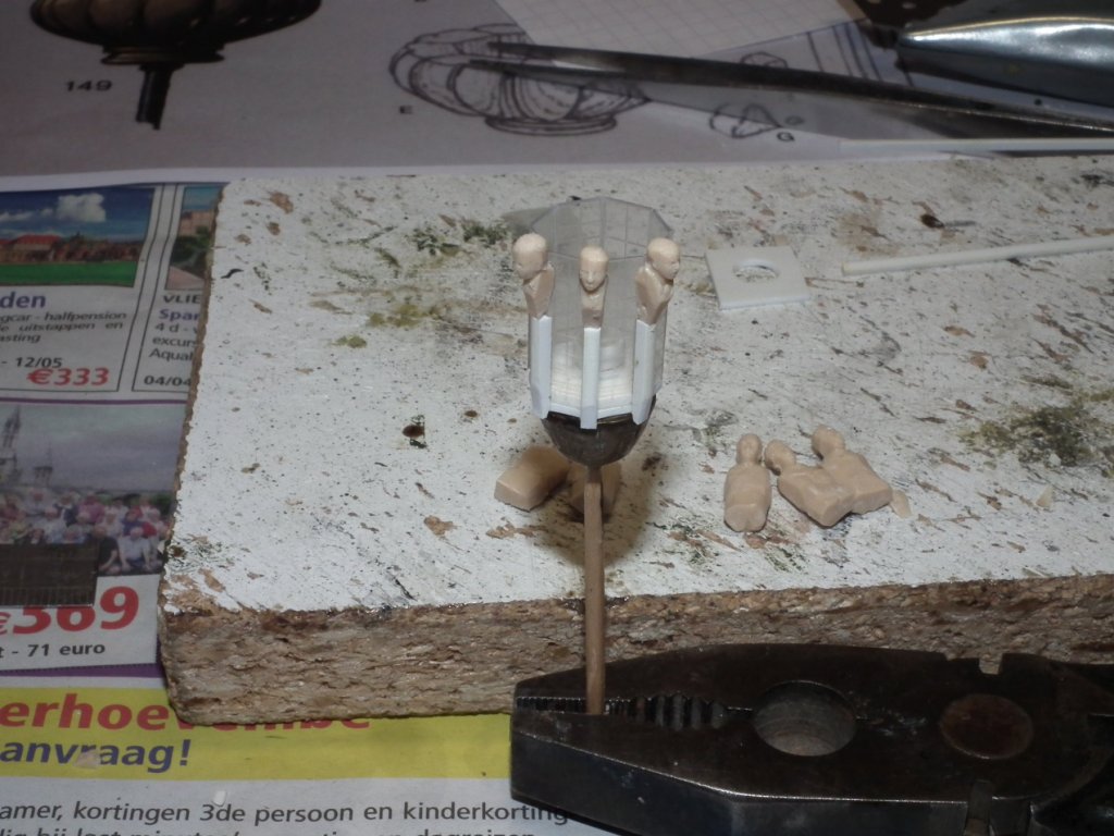


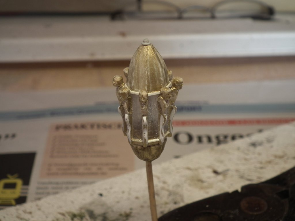
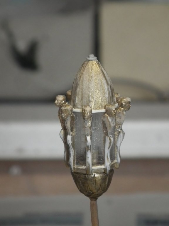
ready
Each question will be answered as good as possible
Groetjes
Greetings
- VACorsair, mtaylor, Chuck Seiler and 8 others
-
11
-
-
thanks Michael and Cristian and everyone watching this
When the fillerblocks are ready on both sides. I will start with building up the frames. ( It is my intention to make the inside partly visible through open doors and windows)
Before I can do this, I first need to determine the final shape
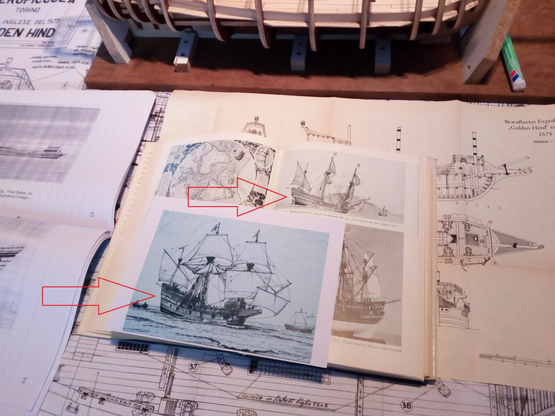
I now have plans and images for 4 different Golden Hinds….( Yes 4 )
The final shape will probably look like this

Groetjes
Greetings


Golden Hind (ex-Pelican) by Baker - FINISHED - scale 1/45 - Galleon late 16th century
in - Build logs for subjects built 1501 - 1750
Posted
Hallo,
The next step is the planking of the hull.
Before I start with this, I have a question.
Should the lowest wale lie above the waterline.
Or may he lie on the waterline or below the waterline.
I have no idea whether there are Rules for this.
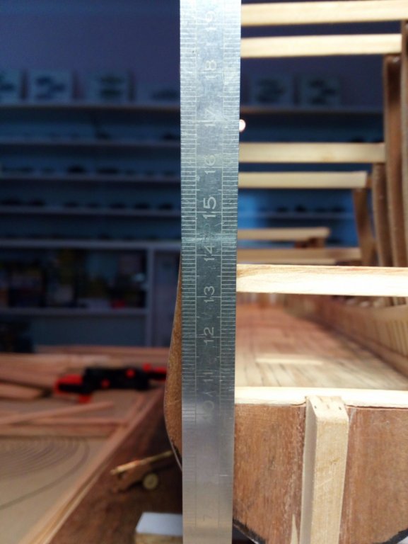
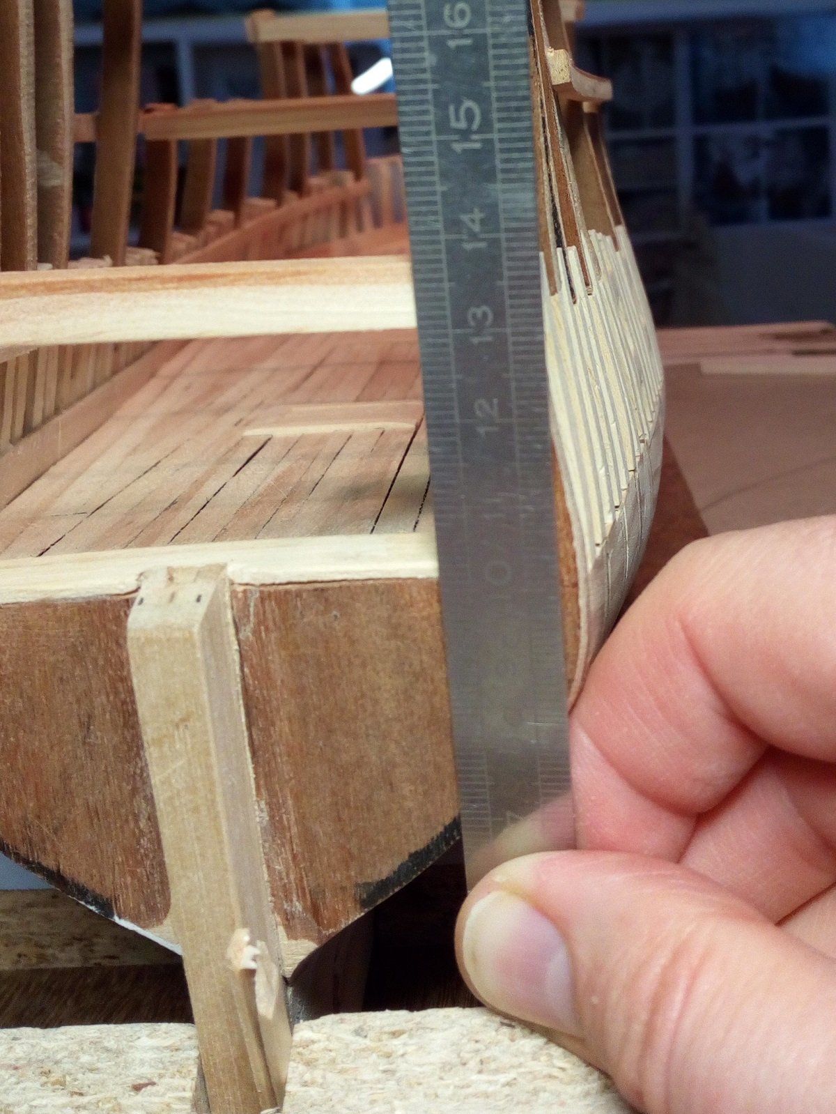
The height of the water line is half of the width of the largest frame
15 centimeter : 2 = 7.5 centimeter (See post with explanation about the possible size of the ship)
The waterline stays where it is now ( at 7.5cm)
Only the height of the wale can be changed
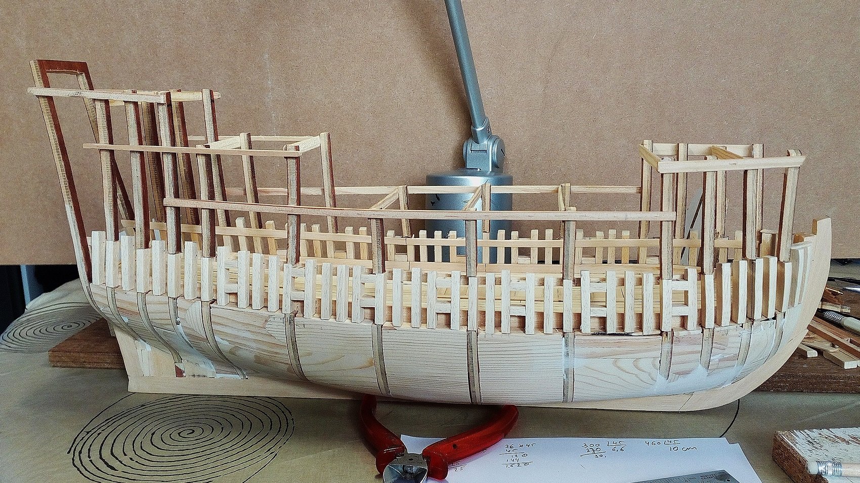
There has been made a trial set-up.
2 wales below the gun ports
1 wale above the gun ports
Like on drawings of ships from that era.
2 wales below the gun ports
1 wale above the gun ports
And a shipwreck
index