

Baker
-
Posts
3,663 -
Joined
-
Last visited
Content Type
Profiles
Forums
Gallery
Events
Posts posted by Baker
-
-
-
-
Well done.
Enjoy the beer
Cheers.groetjes
Greetings
- mort stoll, Barbossa and mtaylor
-
 3
3
-
Thanks,
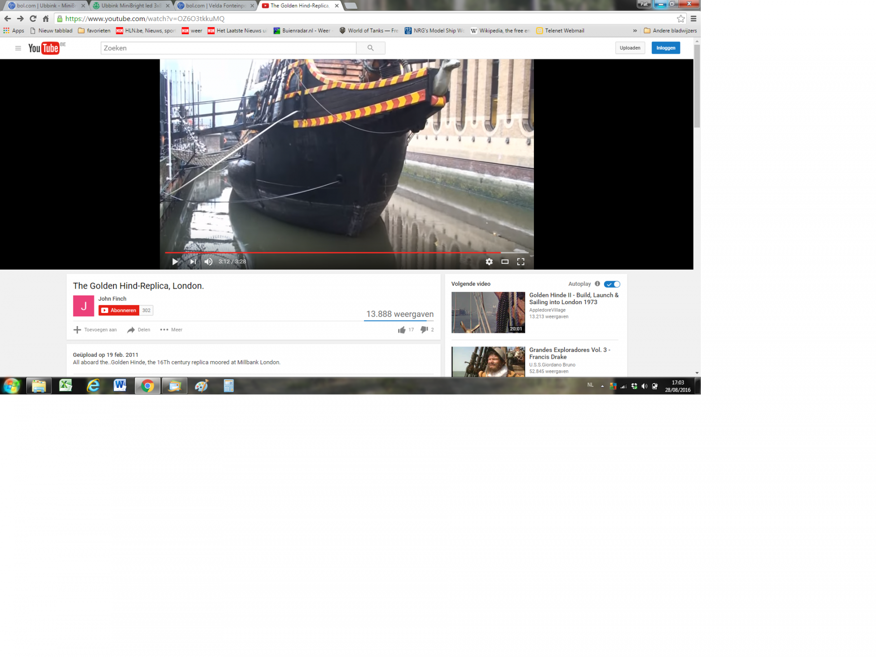
I think that this is the replica that now lies in London. The hull is widened Build in 1973 i thinkWork on the first side is going wellAnd the badly made frame at the stern is almost in correct shape.
index see post 1
Groetjes
Greetings
- zoly99sask, Barbossa, mtaylor and 1 other
-
4
-
-
-
-
A few examples are there in "The art of shipwright" from Matthew baker.

 http://nautarch.tamu.edu/pdf-files/Myers-MA%201987.pdfWhy this is so. Who knows.But Matthew Baker was very respected as a shipbuilder.
Groetjes
Greetings
- druxey, Captain Poison and mtaylor
-
3
-
Normally I give your posts a "like This"
 .But your post N° 368 is the first one i should give a "dont like"
 .Ik zou zeggen
- kin omhoog
- borst vooruit
- en ... nieuwe blokken maken.
- Rome is ook niet op één dag gebouwd
In English :I would say- chin up
- chest forward
- and ... make new blocks.
- Rome was also not built in one day.
Good luck with the new blocks
ps,Actually, I also had to laugh a little first (sorry)Groetjes
Greetings
-
Thanks everyone for the repliesSo we can safely say that this wood is not suitable for ship modeling.And is dangerous firewoodGroetjesGreetingsPatrick
- mtaylor, thibaultron and Canute
-
3
-
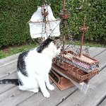
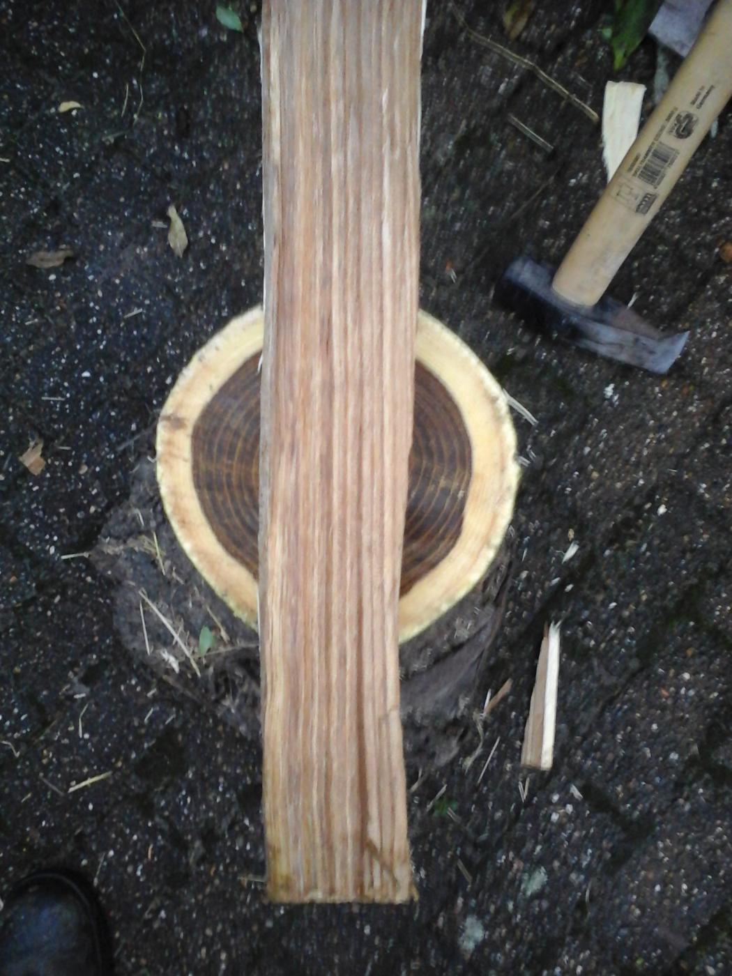
Hello
One of our trees was blown down during a small stormIt is a Laburnum anagyroides or golden chain, golden rain.During sawing this beautiful brown wood appeared.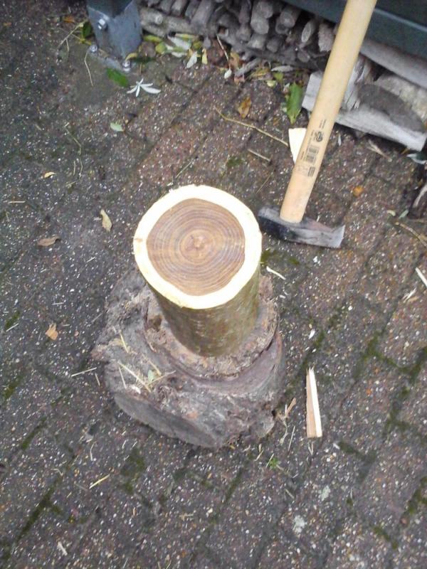
 Does anybody have experience with this?Would it be useful for modeling ??Otherwise, it's firewoodGreetingsPatrick
- thibaultron and Canute
-
2
-
Gewoon toppie Robin !!This can not be translated into English.It just means : fantastic,great job Robin (in Flemish or Dutch)GroetjesGreetingsPatrick
- EJ_L, Robin Lous and mtaylor
-
3
-
Hallo,
First.
A replica is build of the Spanish galleon San Juan.
Great site and beautiful work
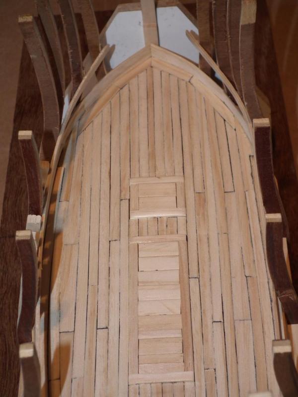
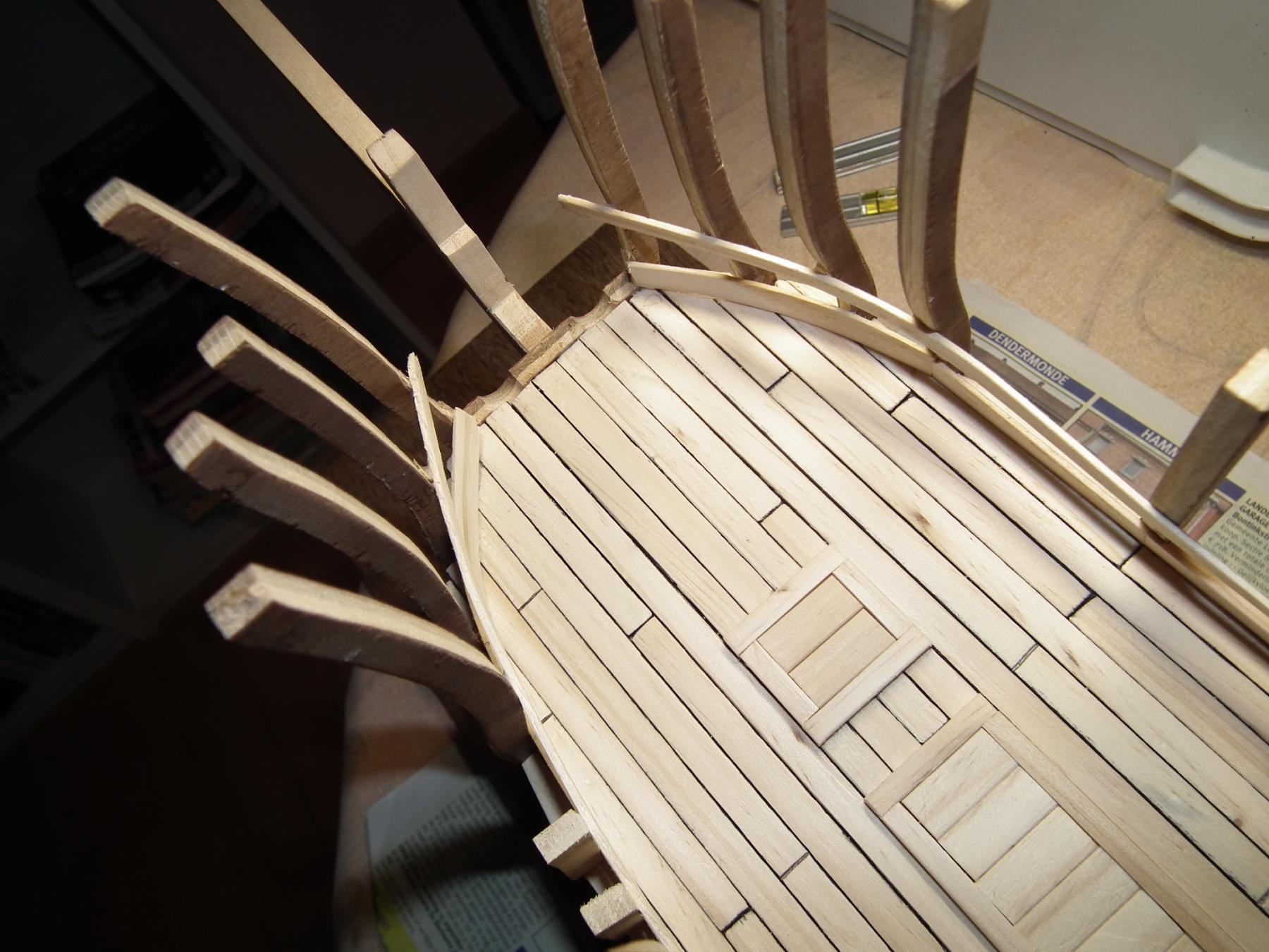
Now : The orlop deck, planking and hatches
Most of this deck will not be visible when the ship is ready.
I see this work as an exercise to gain experience in deck planking.
And if someone looks through a cannon port or a hatch. This will give a better view.
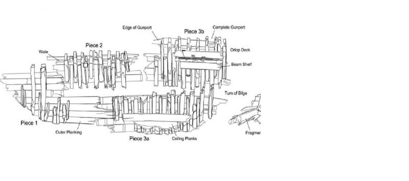
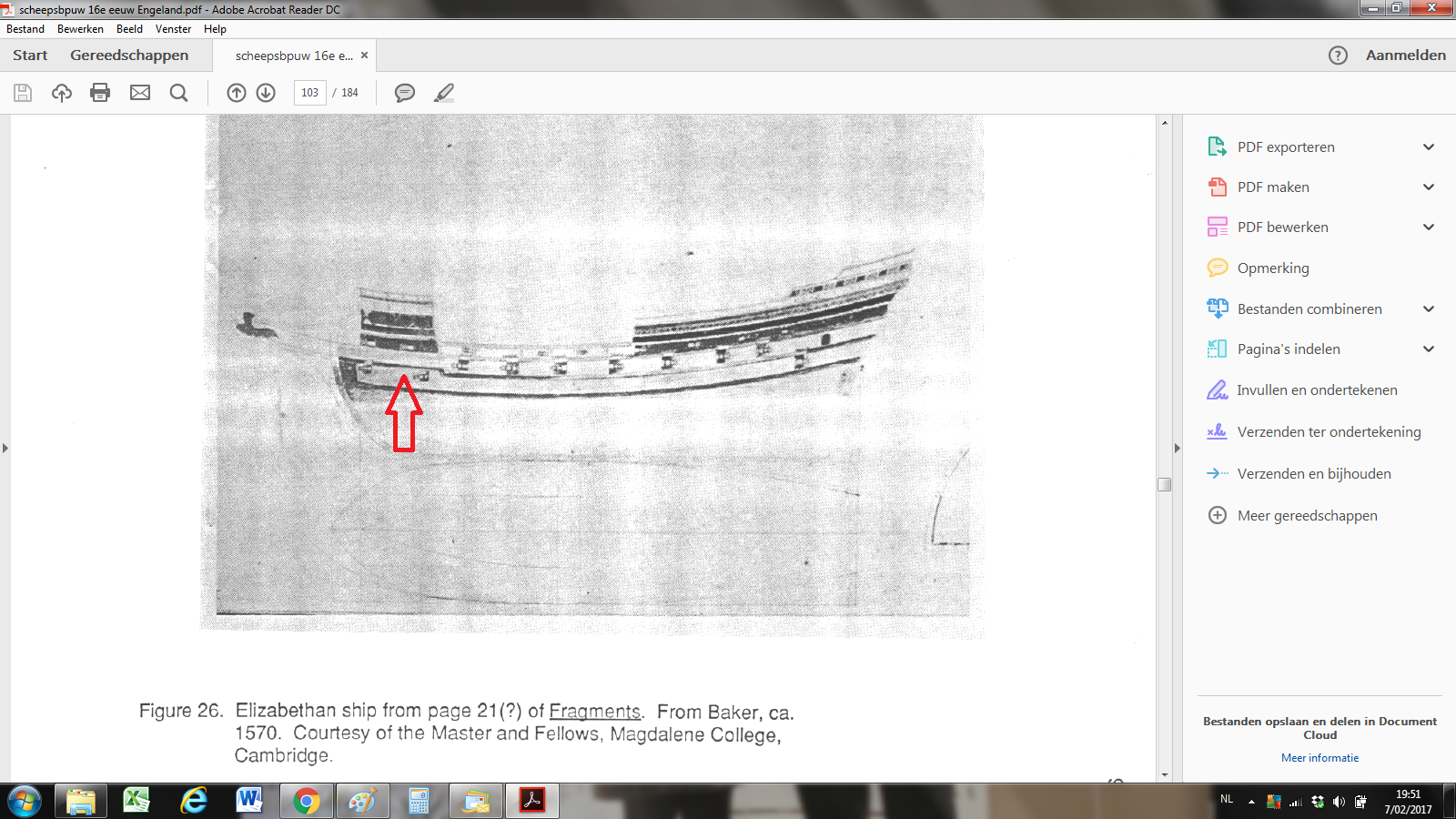
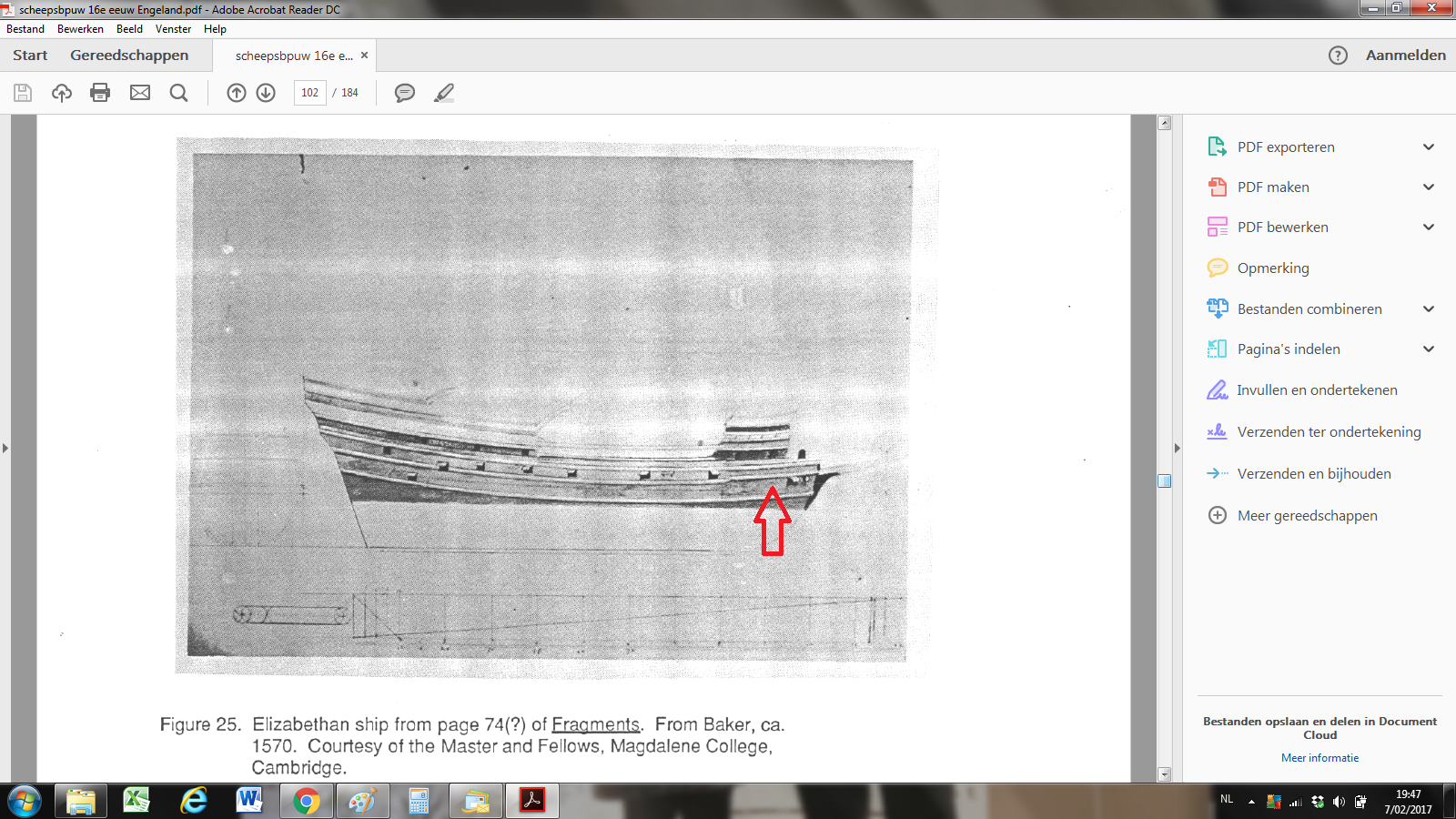
There are little or no archaeological finds of decks from English galleons.
Only from one ship wreck.
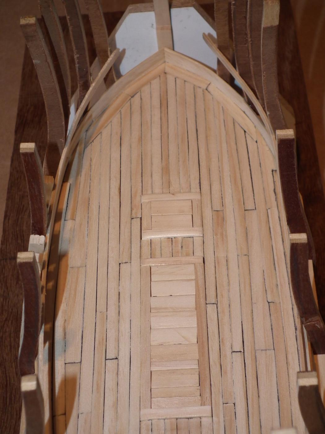
One frame was cut out to low. this was adjusted.
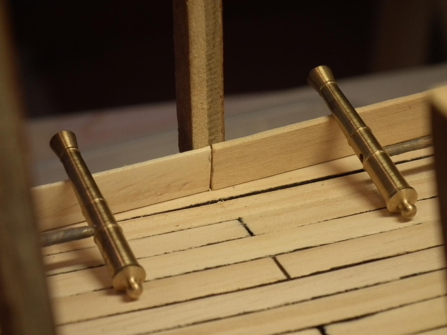
A first layer of planks is laid and sanded. In order to obtain an even surface

The waterway is been placed.

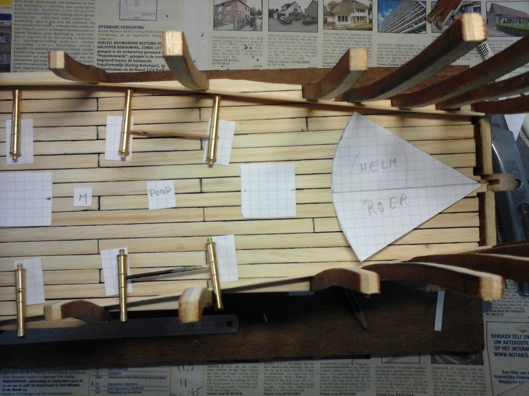
A possible layout of the deck
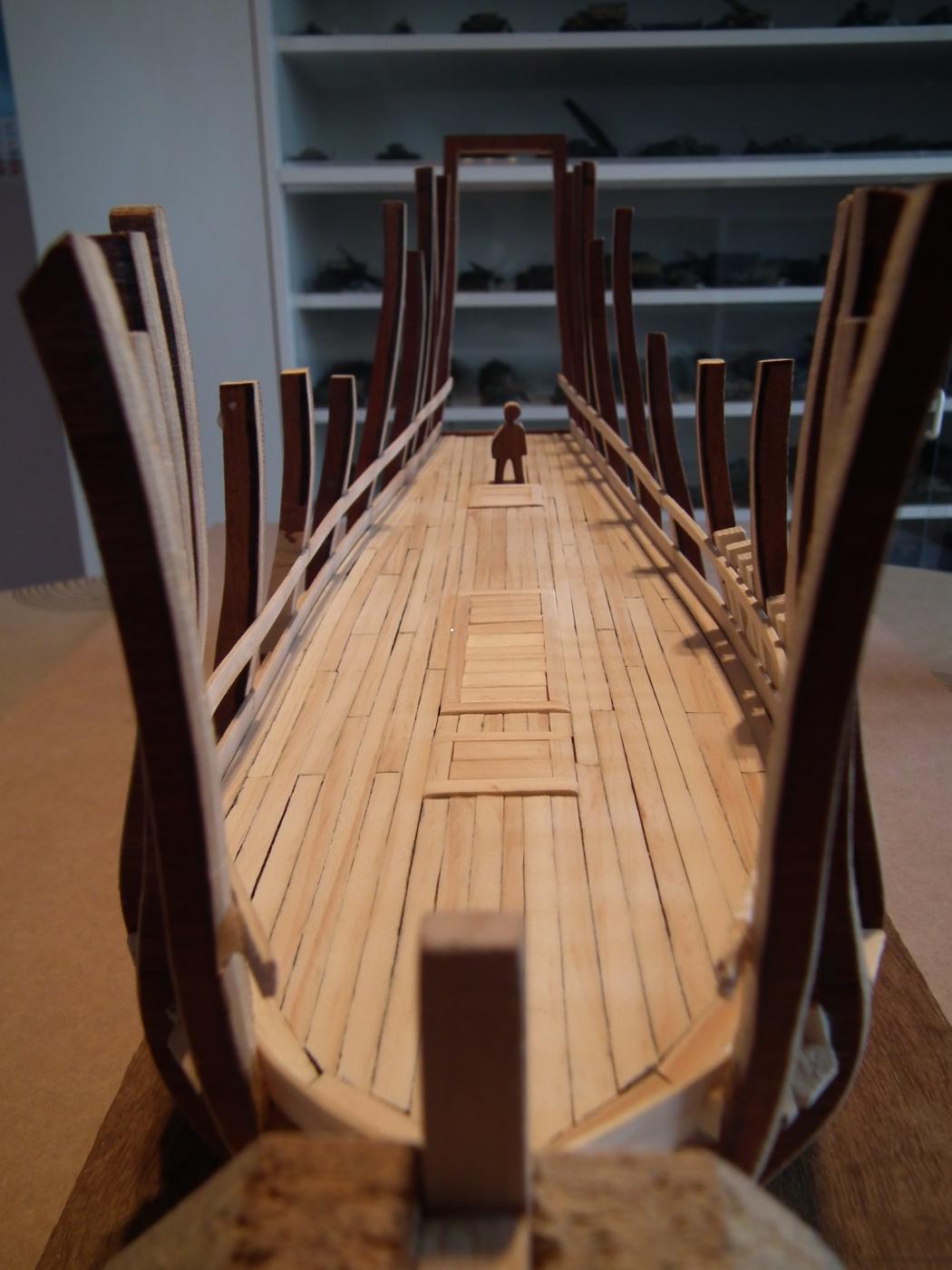
There may be only 12 cannons installed instead of 14 (the helm can possibly be in the way)
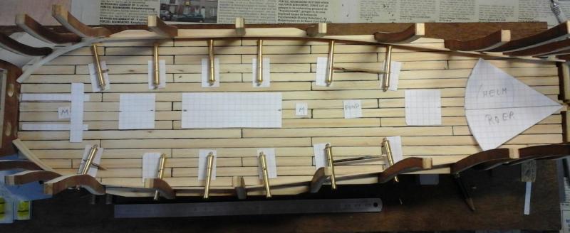
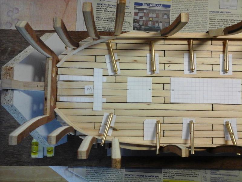
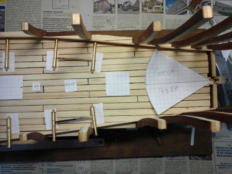
hatches to the lower cargo space
Every time I looked at frame 1. I got a headache
 ....
....
So frame 1 was improved.
Much better now. No more headache

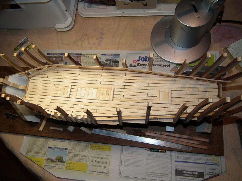
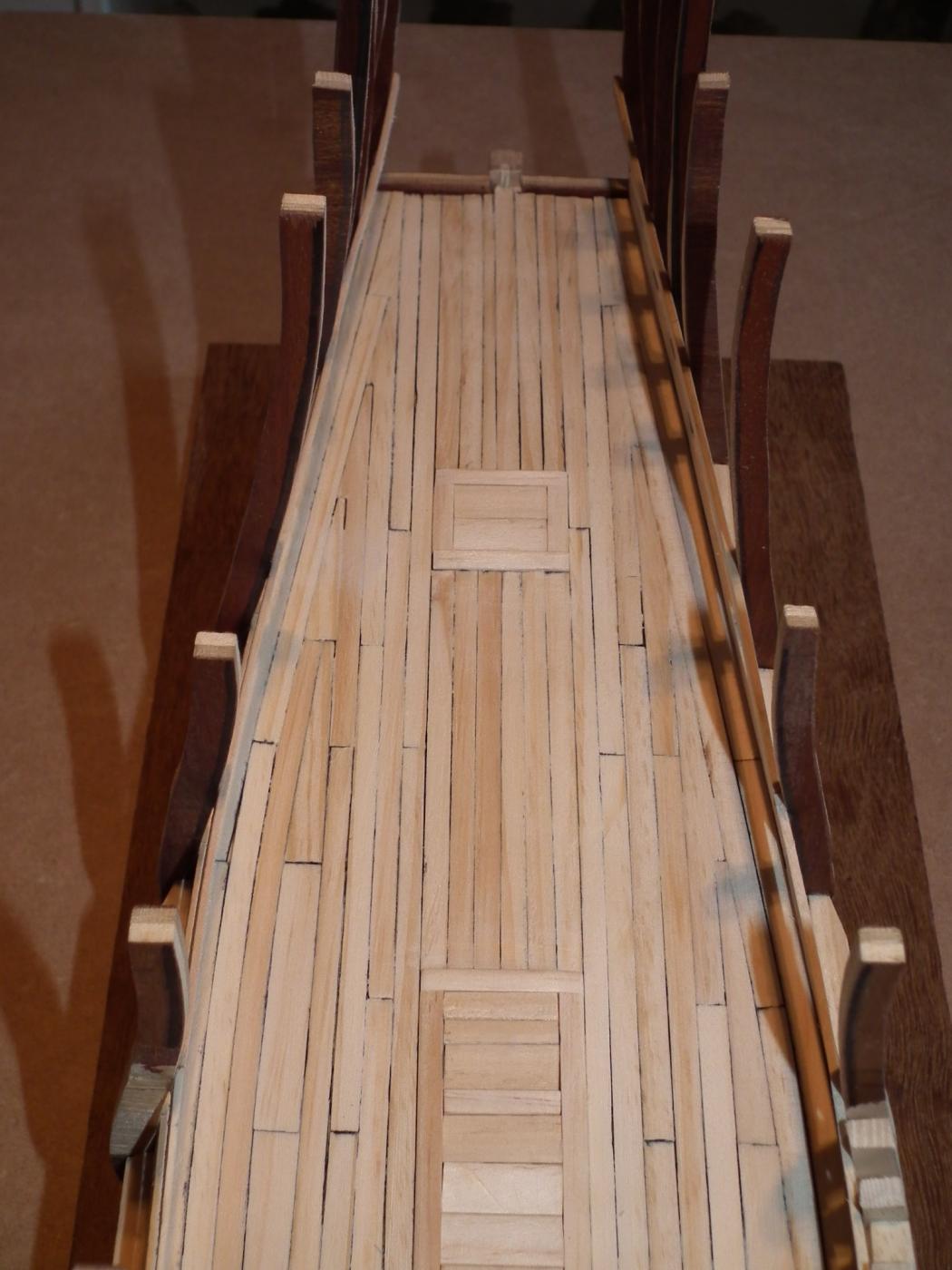
The second and final layer of planking is placed and sanded.
I was so absorbed in this work that I forgot to take pictures while planking the deck
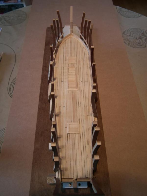
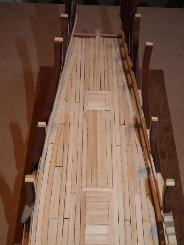
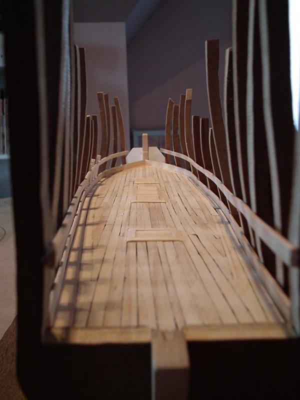

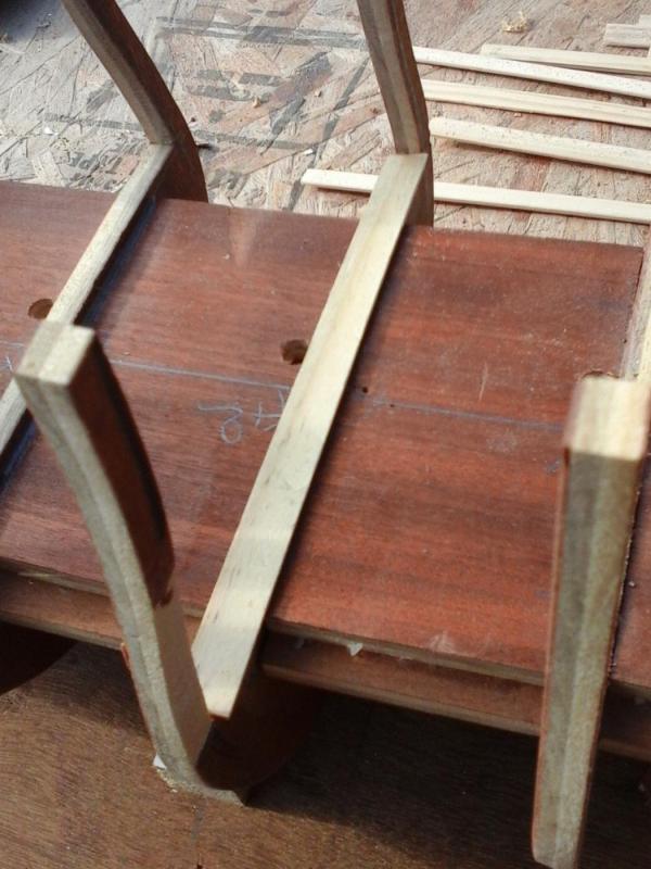
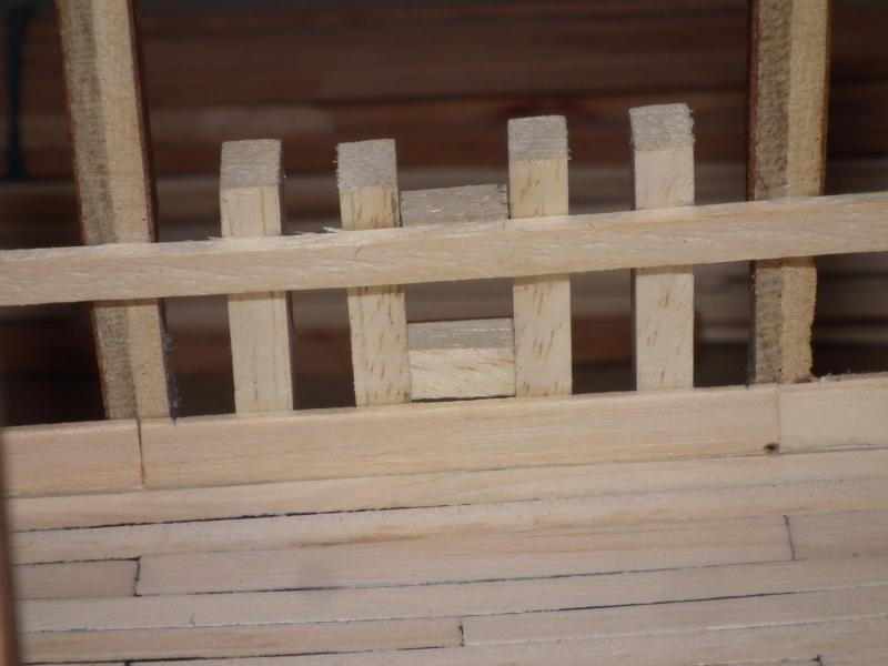
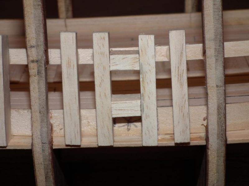
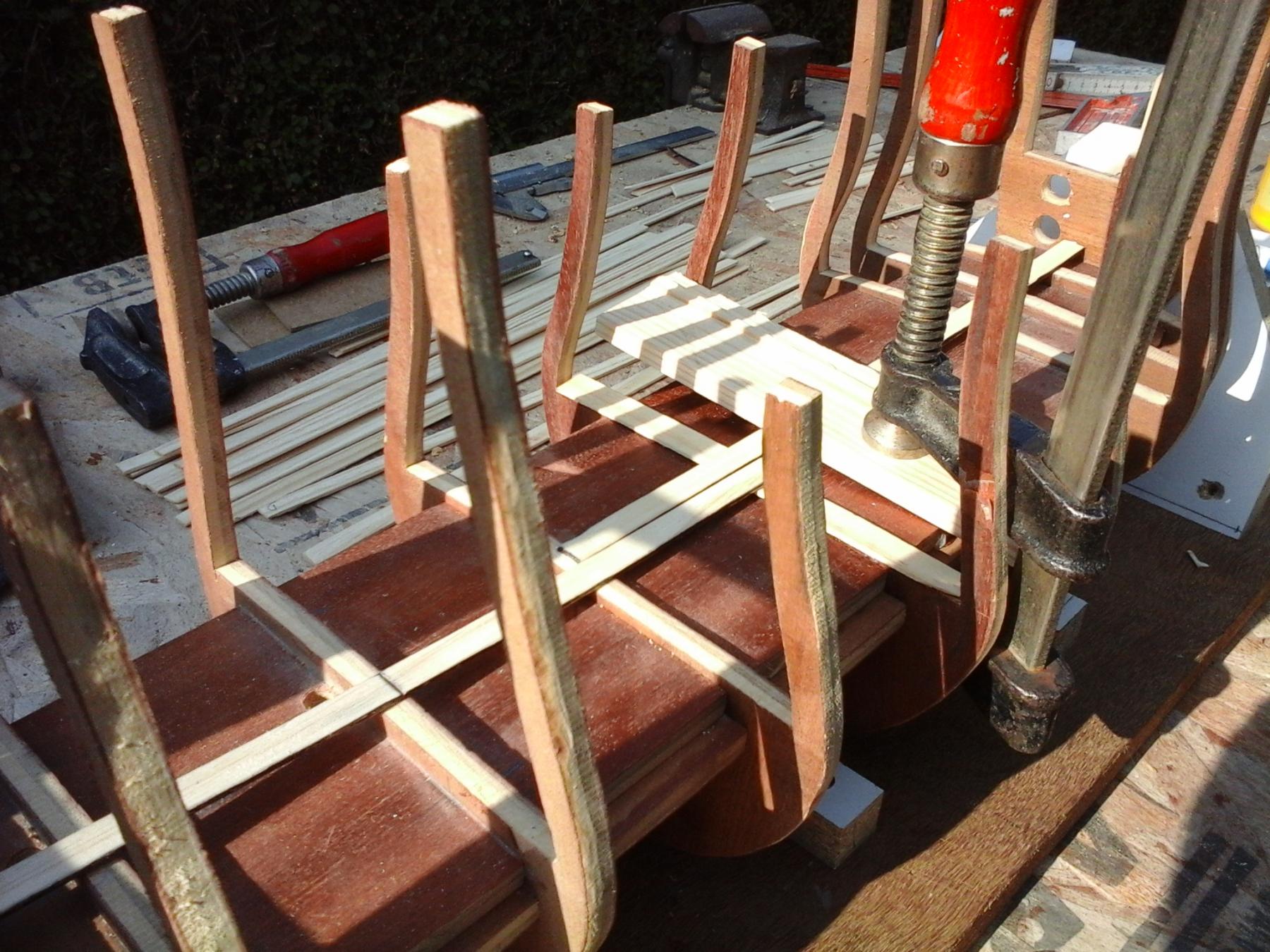
Now to to the dummy frames that will be visible in this deck
1 test assembly of frames and a gun port was made
I'll just lay one layer of planks on the hull
So
The next step is to fill the space between the lower part of the frames.
And adjust the frame of the transom
But it is too wet and cold outside in my gardento do thisAnd I have no indoor space where I can turn on my sawing machineSo back to plastic military modeling. Index : see post 1GroetjesGreetingsPatrick
- WBlakeny, mtaylor, zoly99sask and 6 others
-
9
-
Kurt,
I started building the Golden Hind.
In particular, it looks that the shape of the underside of the hull is important.
Look at the links on my build log of the Golden Hind.
Or, just ask.
I try to do my best to reply (But I'm not a specialist
)There will by an update of my buildlog soon .
Here's a picture in preview
Groetjes
Greetings
Patrick
-
-
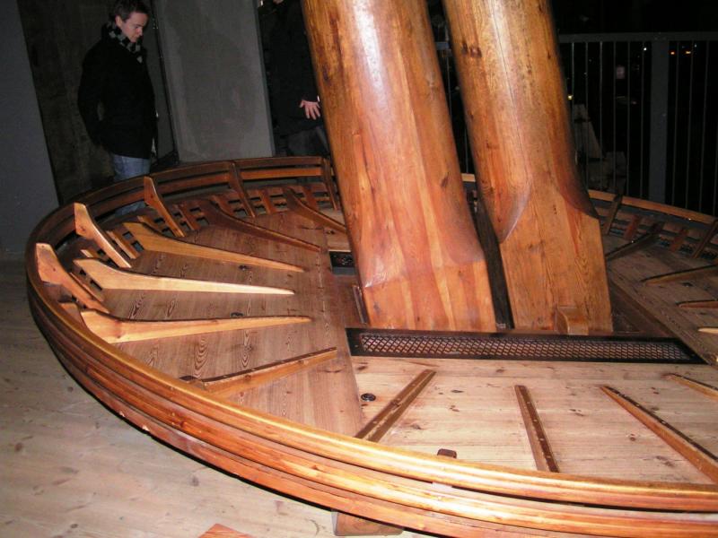
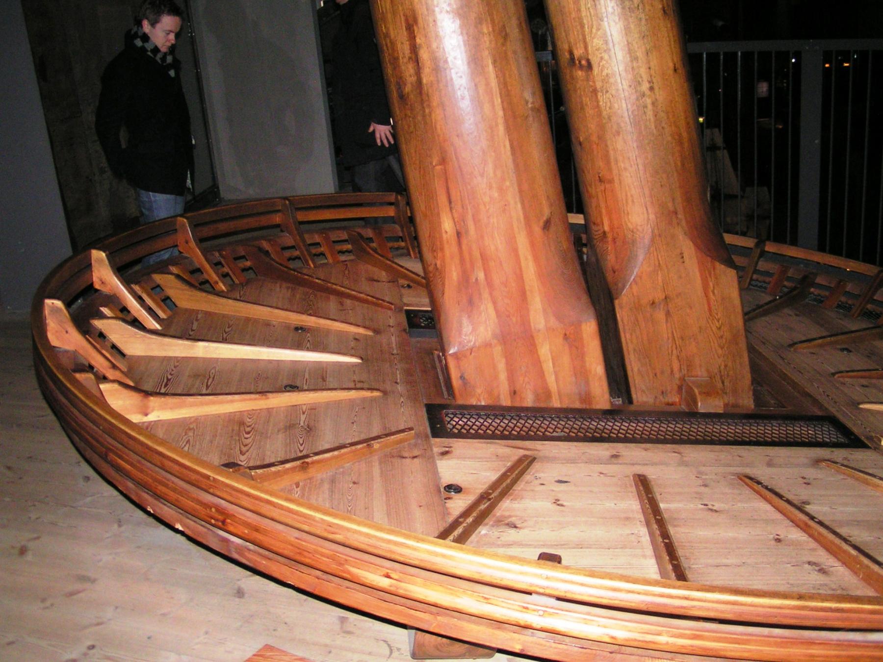
Hey MichaelNicely done as alwaysHere you have a picture of the other sideTaken in the museum.
 Take a look at the Wasa plans from Billings.Who also use a "fid"
GroetjesGreetingsPatrick
- WackoWolf, NMBROOK, CaptainSteve and 2 others
-
5
-
Nice workFunny,We use the same tool to cut round circels from styrene sheet.A simple tool which cuts always nice round shapes.GroetjesGreetingsPatrick
- Old Collingwood, dgbot, EJ_L and 4 others
-
7
-
-
Well done Robin !!A very highly detailed model, to be proud of.This has nothing to do with ships but is very interesting for you (and me) .You should try it.1 bottle of cheap cognac, NOT brandy1 orange (prick with a knife in it)40 lumps (klontjes in dutch) of sugar40 coffee beansDo this in a pot and wait 40 days, but shake it every 10 daysyummy ...
 GroetjesGreetingsPatrick
- mtaylor, zoly99sask, Robin Lous and 1 other
-
4
-
Thanks for the info about the stern.
have checked this and will certainly change this later
the book looks interesting.
I ask it for my Christmas at the Admiral.
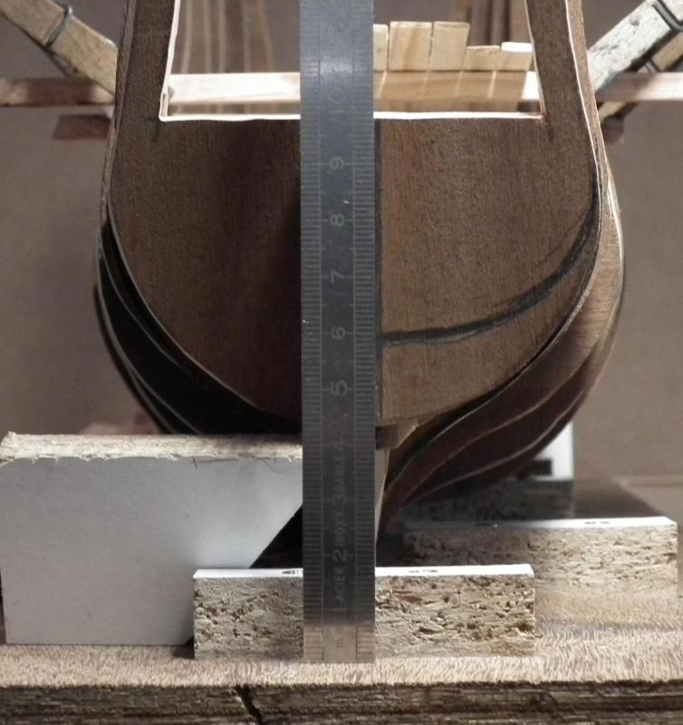
Now,
The whole idea behind my question about the height of the deck
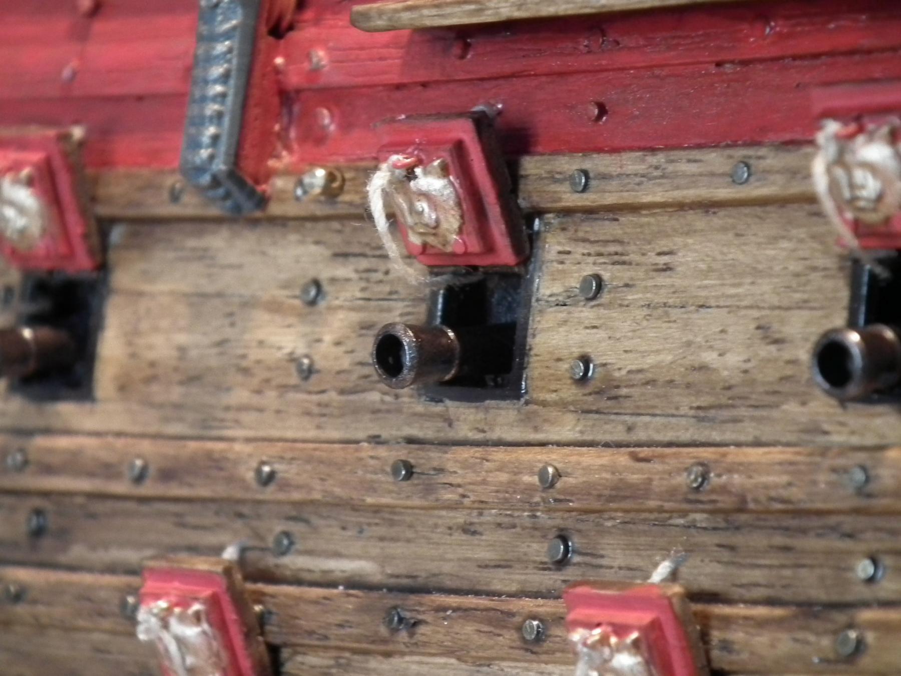
I want open cannon ports
And I don’t like the building method as in my Wasa (black holes with semi cannons).

That's why I want a deck with enough detail. So, that if you look through a porthole. You do not see black hole with a part of a cannon. But a real cannon and a deck.
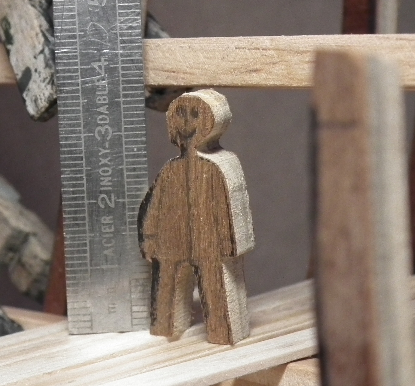
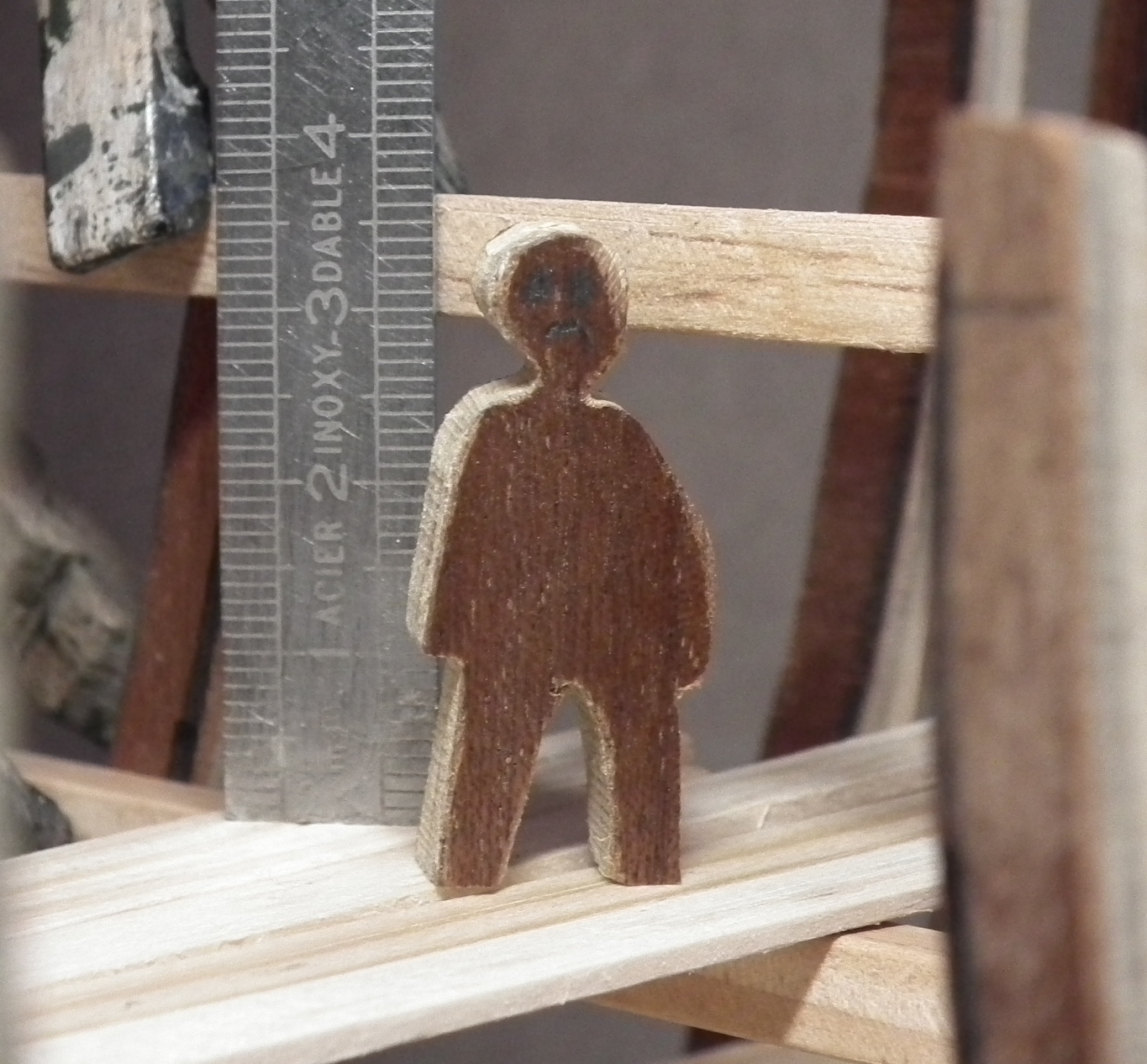
I hired an assistant. He is 1m60 tall, very cheap and is satisfied with no room and no food.
But. A deck of only 1m60, is too low he thinks .
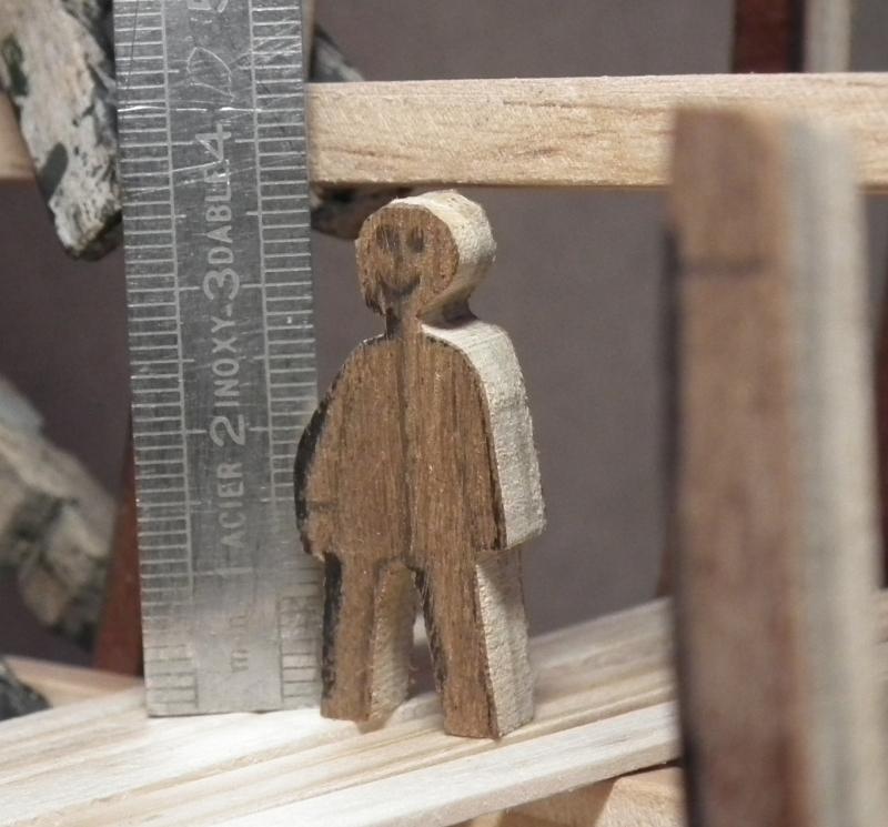

but there is still plenty of time to think about this
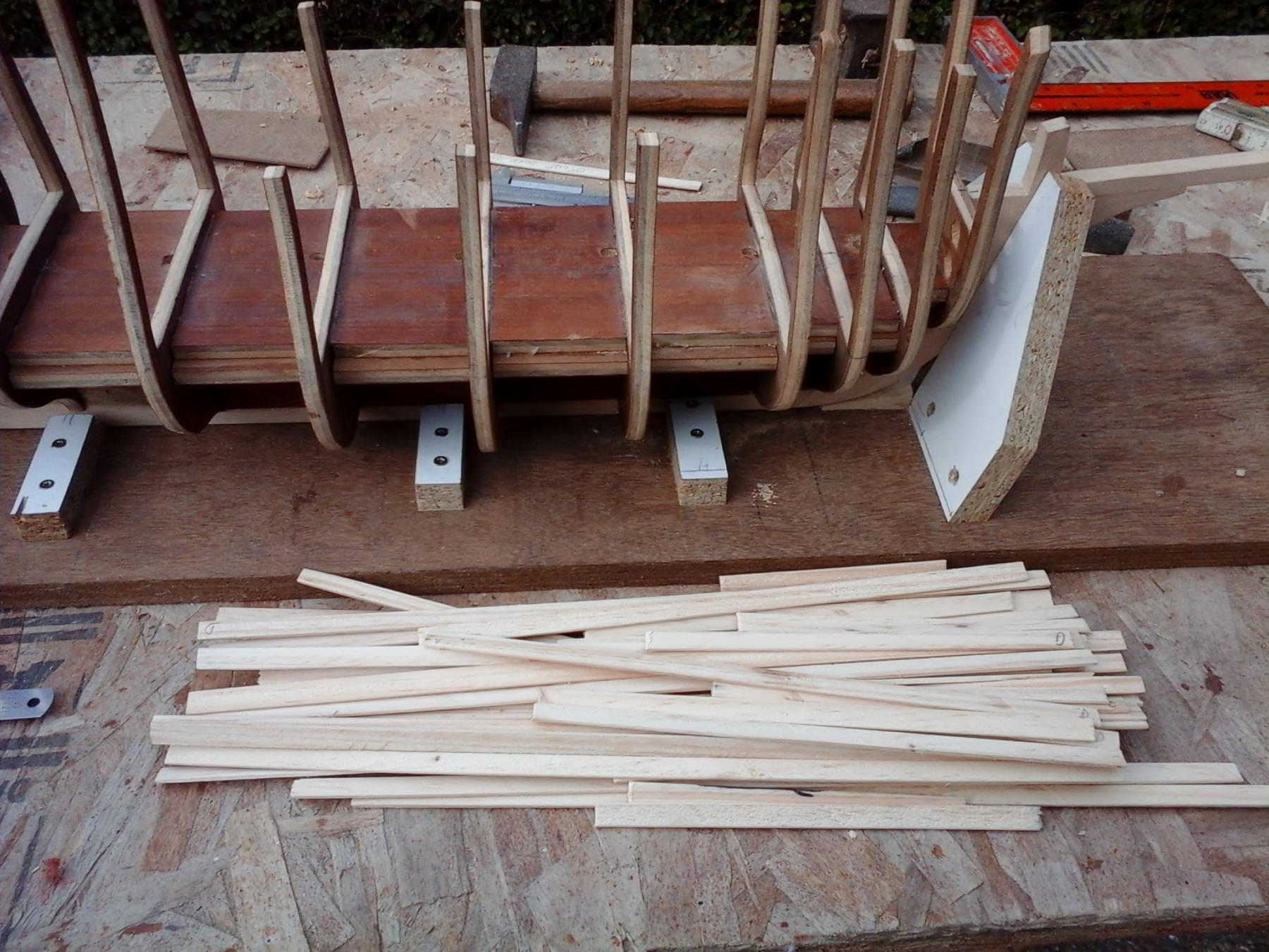
And good news
Yesterday we had beautiful weather and no family visits or jobs
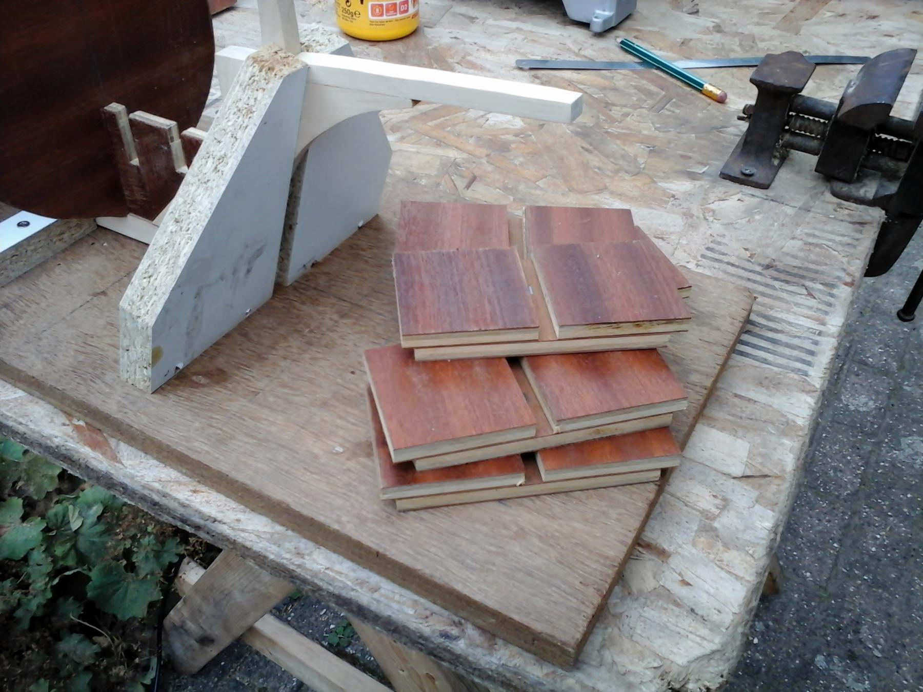
So, there was wood sawed and the part where te deck is too be attached is sanded to

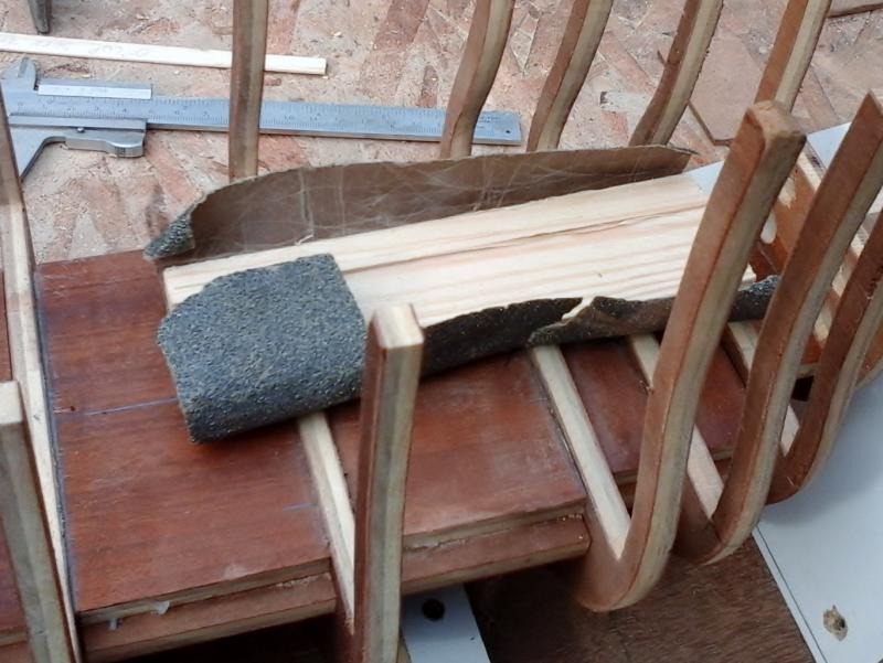
So that I can start with my deck in my hobby room. Without having to make a lot of dust...
so Mrs. Backer stays happy alsoGroetjes
Greetings
Backer
-
Thanks everyone for following my build log.
And thanks Steven to match with my vision on the dimensions.
Well, now I need some help.
I can not find what the height of the cannon deck (orlop deck) should by.
Does anyone know the height between 2 decks
I think it is 1m60 (The average length of a man in the 16th century)
Groetjes
Greetings
Patrick
- mtaylor, SigEp Ziggy and zoly99sask
-
3
-
Well, the shipyard is on hold. But here is something to disscus about.Before drawing the frames i had 2 difficult questions :1 . What are the dimensions and tonnage of the Golden Hind?
Well, even Wikipedia does not match
wikipedia (in english): length (deck) 31m, beam : 6.1m, tonnage 100 - 150 ton
wikipedia (in german): length 37m, beam : 5.5m, tonnage ,? ton
Most sources say 100 and 120 tons. Occasionally 150tons, and somewhereone I found one
that says 180 tons.
The length is between 31 and 37 m.Length on deck 25m.
So no one really knows the right answer.
2. What is the scale that I'm going to build?
And what will be the dimensions and tonnage of the Golden Hind compared too the scale i am building
After some calculations. The scale of my model will be 1/45.
Too calculate the scale and dimensions i used the help from a formula.
Keel x Beam x Depth Keel x Beam x Depth
----------------------------- = Tonnage or (the easy way) ---------------------------
Keel + Beam + Depth 100
And 1m = 3.28 feet.
My model is :
Keel 0.42m - Beam 0.15m - Depth 0.075m - scale 1/45
Keel = 0.42x45x3.28 = 61.99 feet
Beam = 0.15x45x3.28 = 22.14 feet
Depth = .075x45x3.28 = 11.07 feet
This gives following dimensions
- Tonnage : 161 tons or 154 tons with the easy formula.
- Length on deck will be : 22.95m = 75.27 feet
- Length of the hull will be 32.6 m = 106,92 feet
- Overall length will be : 37 m = 121.36 feet
- width of the hull will be : 6.75 m = 22.14 feet
- Depth will be : 3.37m = 11.07 feet
- ratio keel / beam : 2.8
How to get between the 100 to 120 tons and retaining the length of 31 to 37m (like mentioned in most sources).By reducing the beam and - or depth.
Suppose :
Keel = 0.42x45x3.28 = 61.99 feet
Beam = 0.13x45x3.28 = 19.19feet
Depth = .065x45x3.28 = 9.6 feet
This gives 113 tons or 114 tons with the easy formula.
But in doing so, the ratio keel / beam changes to 3.23
If you compare the studies about the Gresham ship, furring and ship building in the 16th century.
Than a keel/beam ratio of 3.23 leads almost to a “crank ship”
A logical consequence is that a ship of that length with 100 to 120 tons is quite narrow and maybe not stable. Especially if you then put all the guns on the upper deck. As on some ship models.
Unless one increases the depth drastically. in order to increase the stability.
I was never a highly educated student (now also not). But :
A ship that could sail around the world and could conquer a bigger Spanish galleon. Must be seaworthy and should by a stable platform to fire his guns.
If anyone thinks that I am completely wrong about this
Please let me know. I have all winter to think about it
used links for this study
http://www.maritimearchaeology.dk/downloads/Full%20thesis%20bates.pdf
http://www.wessexarch.co.uk/files/PMA41.2Auer-Firth.pdf
http://nautarch.tamu.edu/pdf-files/Myers-MA%201987.pdf
http://www.patrimoniocultural.pt/media/uploads/trabalhosdearqueologia/18/22.pdf
http://www.bricksite.com/uf/40000_49999/48372/7e570040536647340b5566f37c70ca11.pdf
Groetjes
Greetings
Patrick
-
My opinionA kit. so old.
- The decals will probably fall apart if you put them in water.
- The plastic looks ok. But if it is from a "short run" manufacturing. then The quality will be very low.
- You will want, or need to replace many parts (Extra cost).
AndYou will, after much work, end up with a model which costs almost as much as a new model kit.But with less work.I would not do itGroetjesGreetingsPatrick
- The decals will probably fall apart if you put them in water.
-
Hello,
First. I changed the name of my build log in too
“Golden Hind : A English galleon late 16th century” (Seems more appropriate)
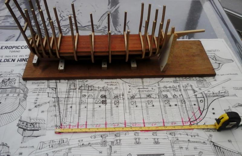
New frames are drawn on paper and cut out.
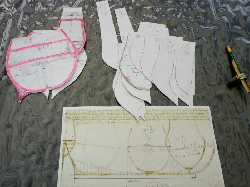
There are now more frames used on the bow and the stern than first planned
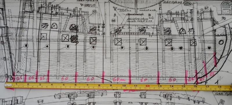
Then the frames are drawn on plywood and sawed. The beam is 4 cm narrower than the one on the plans.
The hull proportions are
KEEL / BEAM : 2.80
DEPTH / BEAM : 0.50


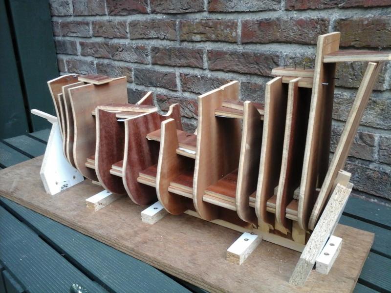
All the frames are made too high ( sawing off a piece of is easier than to glueing on)
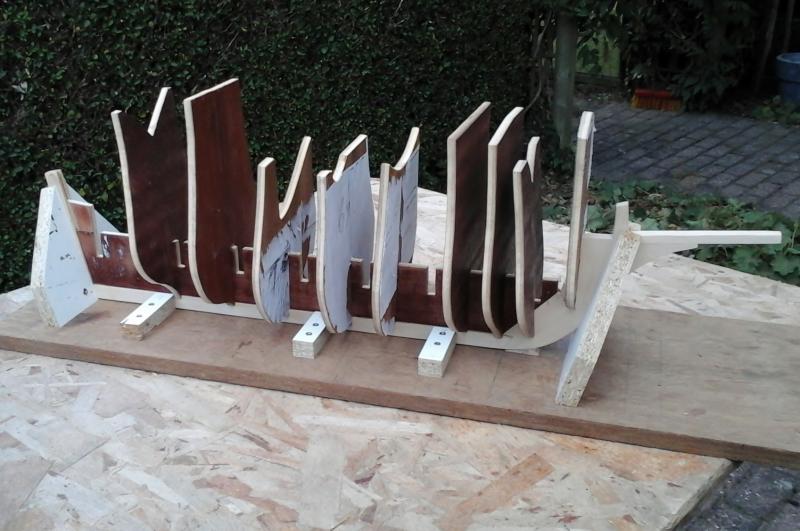
Reinforcements are sawn from plywood and glued to the keel.

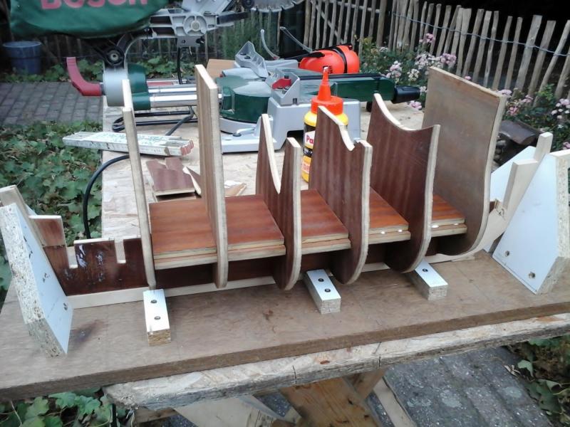
The frames are not glued yet. But are now temporarily attached to the keel. So i can see if they fit and that outside can be sanded where needed.
When the outside is sanded, the frames are removed again so that the inside of the frames can be sawed out.
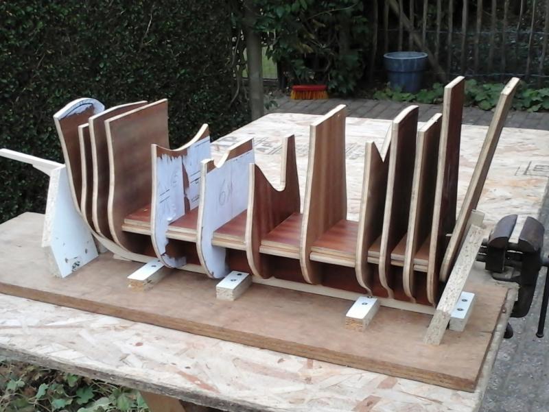
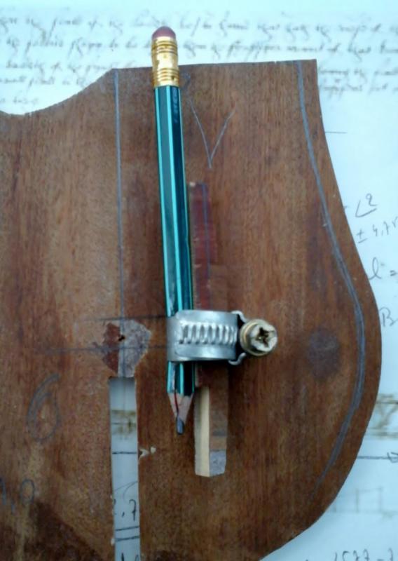
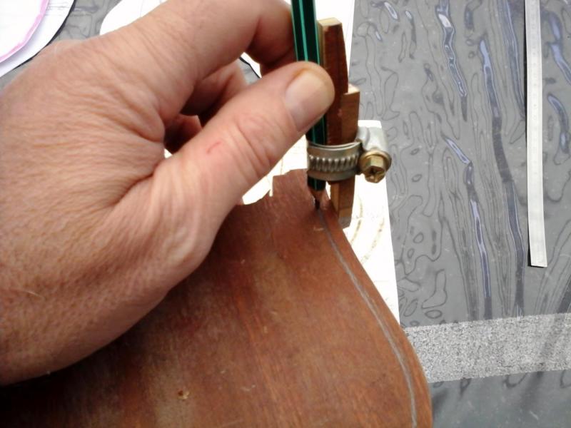
The sawing of the inside of the frames can begin.
I made myself a simple tool for this .
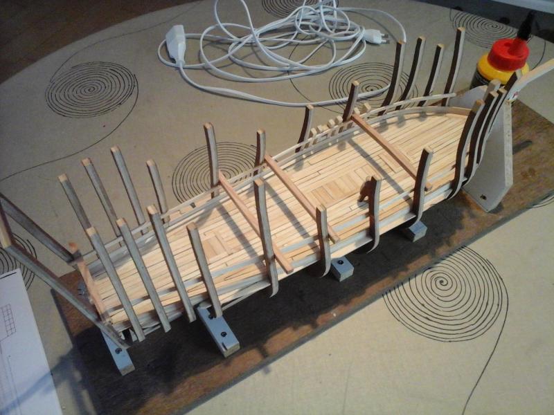
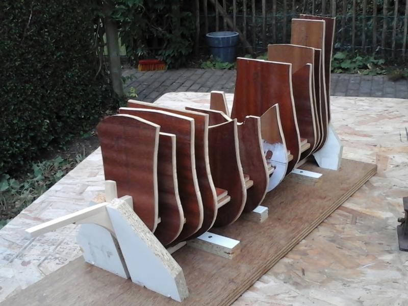
The first frames are aligned and glued.
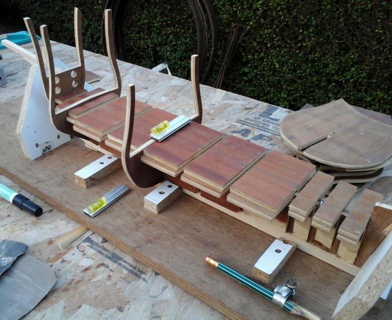
All the frames are now aligned and glued.
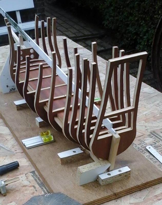
Visible parts of the frames on the upper decks will later be replaced by solid wood.
It looks like I go in the right direction I think.
The shipyard is now temporarily "on hold"
Autumn and winter period is for me : military modeling.
But I remain of course to follow MSW.
Groetjes
Greetings
Patrick
- Louie da fly, mtaylor, SigEp Ziggy and 8 others
-
11


Golden Hind (ex-Pelican) by Baker - FINISHED - scale 1/45 - Galleon late 16th century
in - Build logs for subjects built 1501 - 1750
Posted
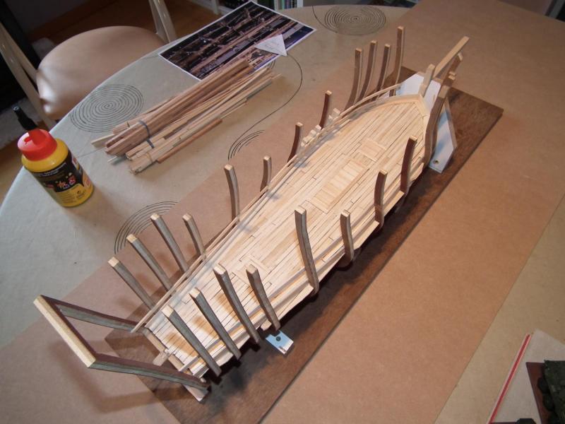
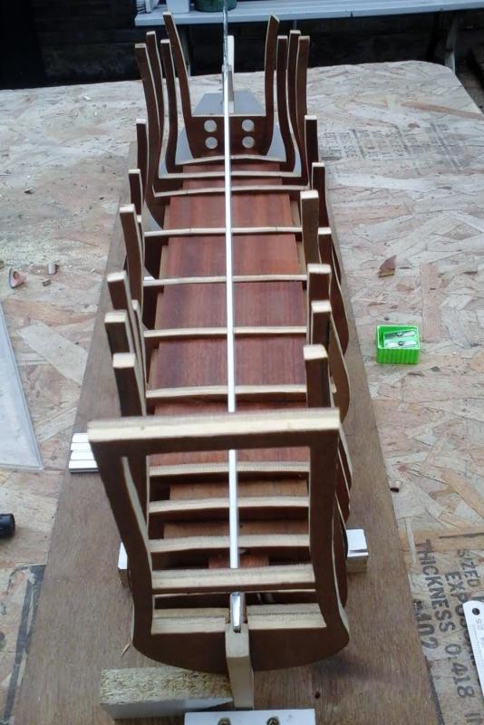
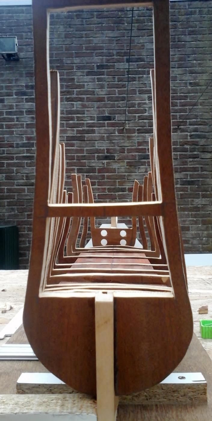
Hello
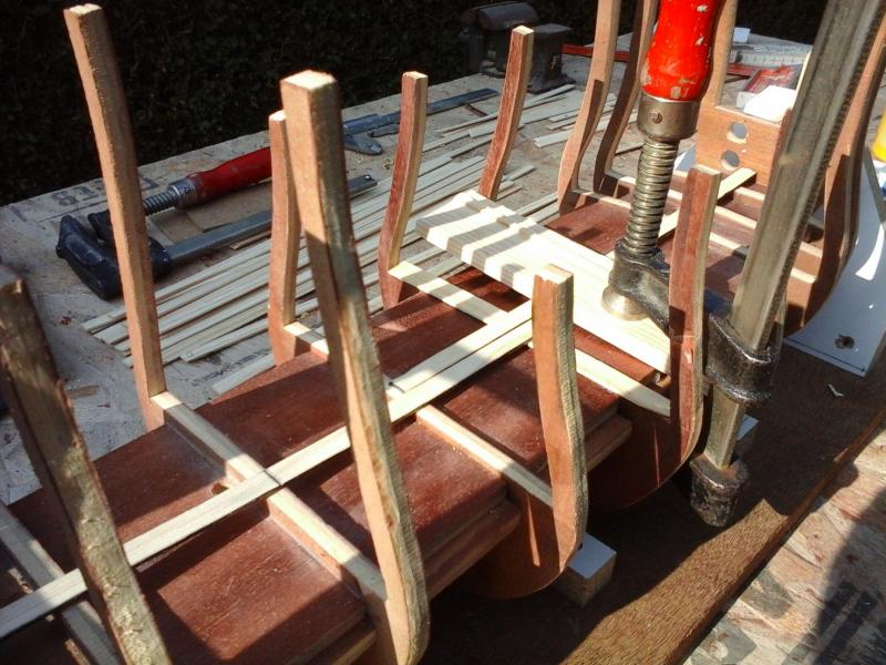
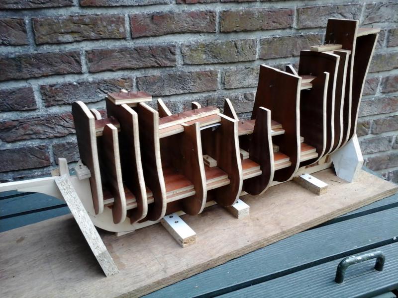
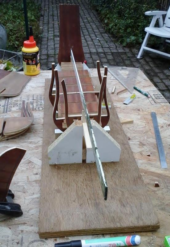
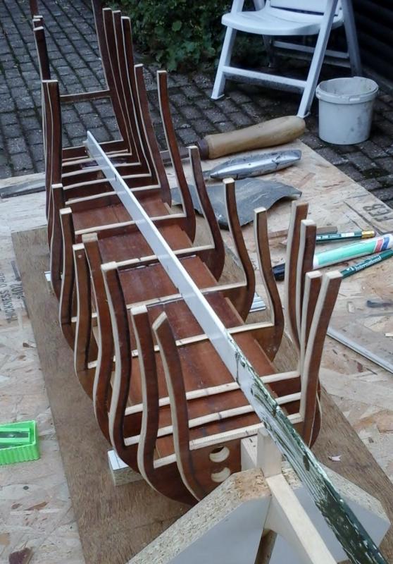
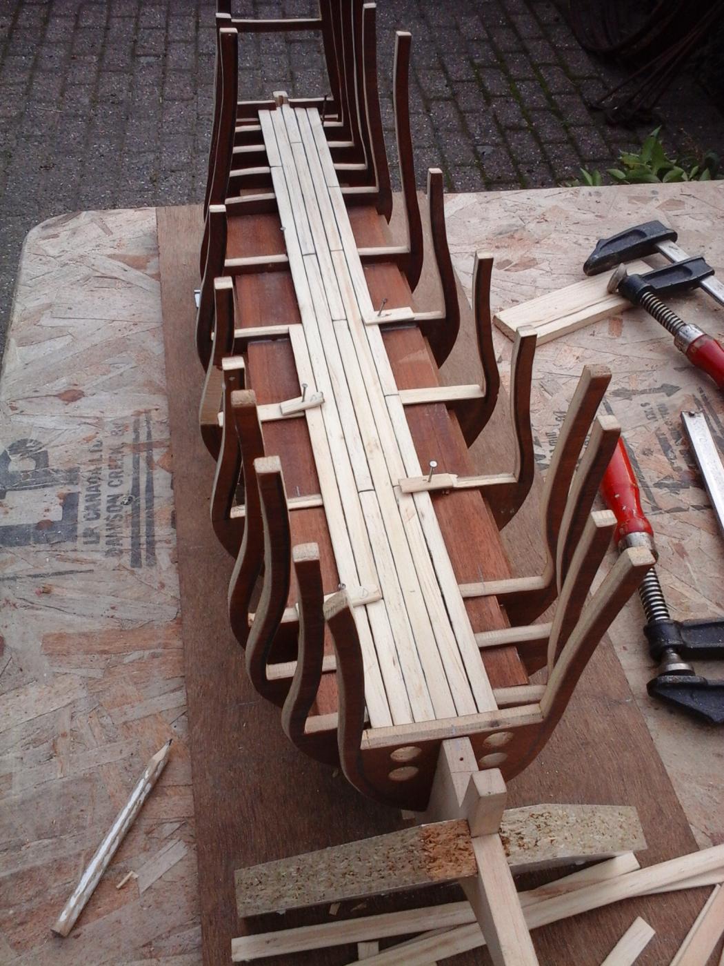
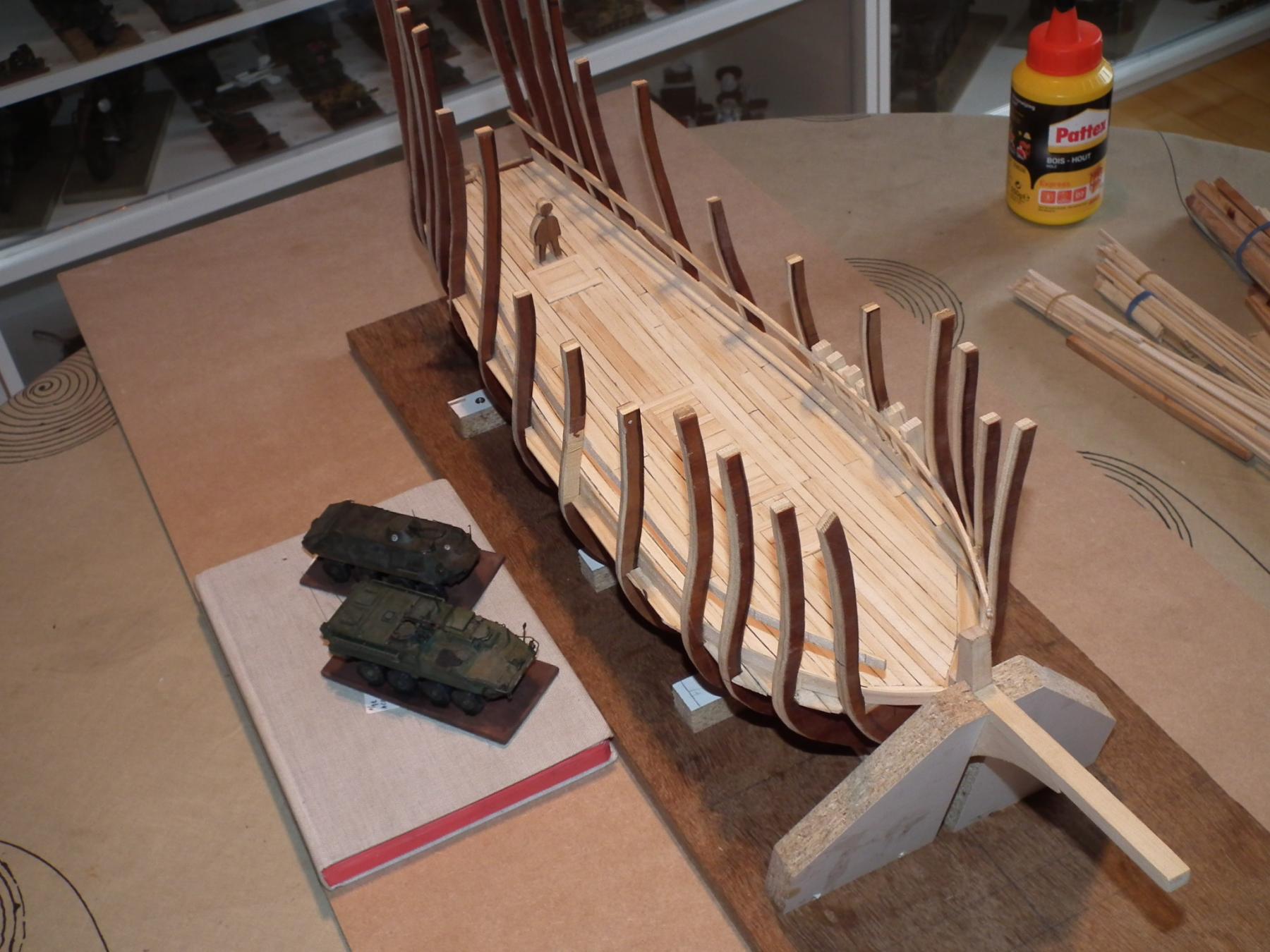
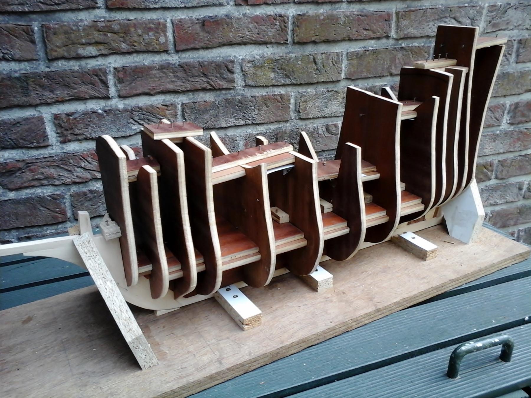
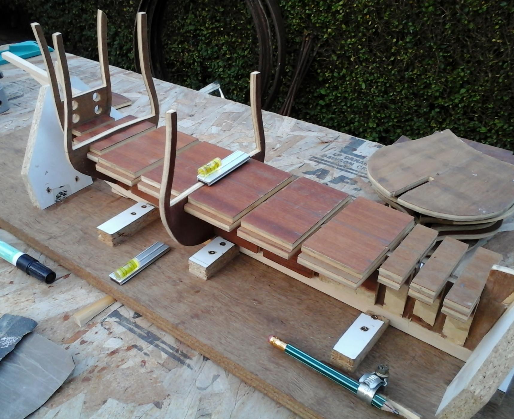
The upper ends of the frames are provided with supports.
So that they can be less easily damaged.
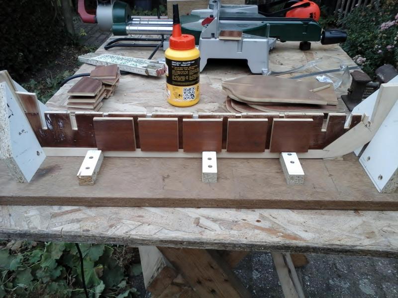
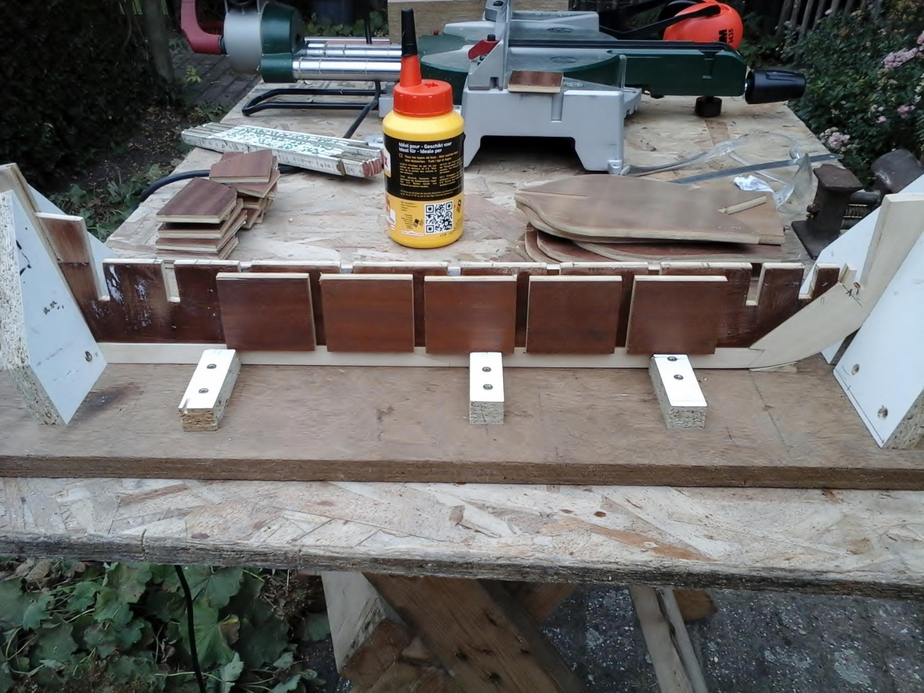
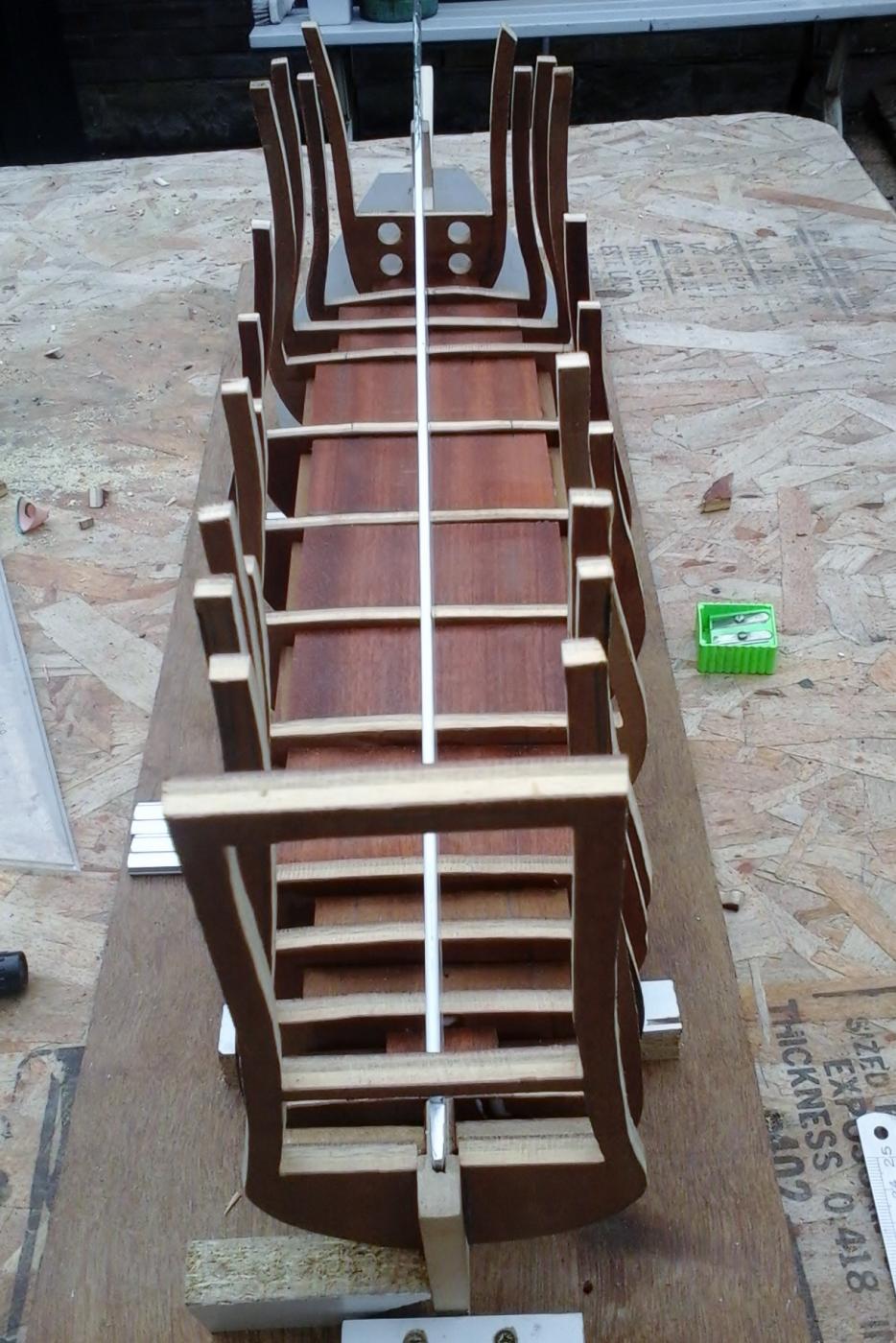
I started with the filling of the lower space of the frames ( i think "fillerbloks" is the correct word).
Wooden pieces are sawn to length.
These pieces are then made at approximately the right shape.
And glued between the frames
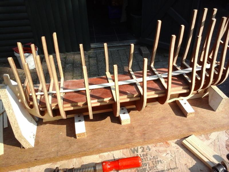
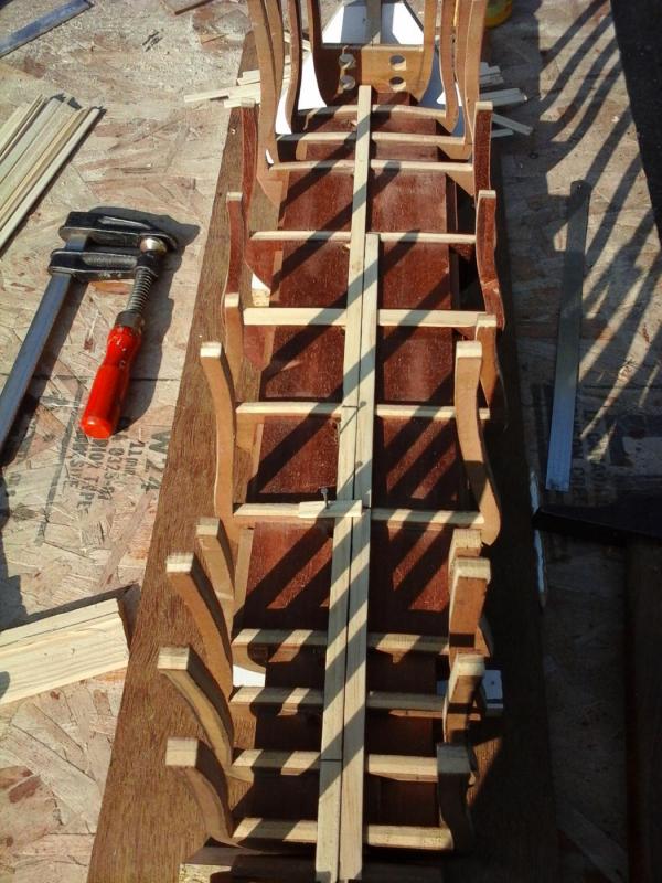
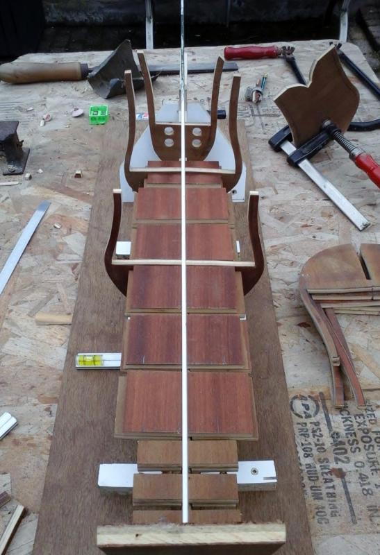
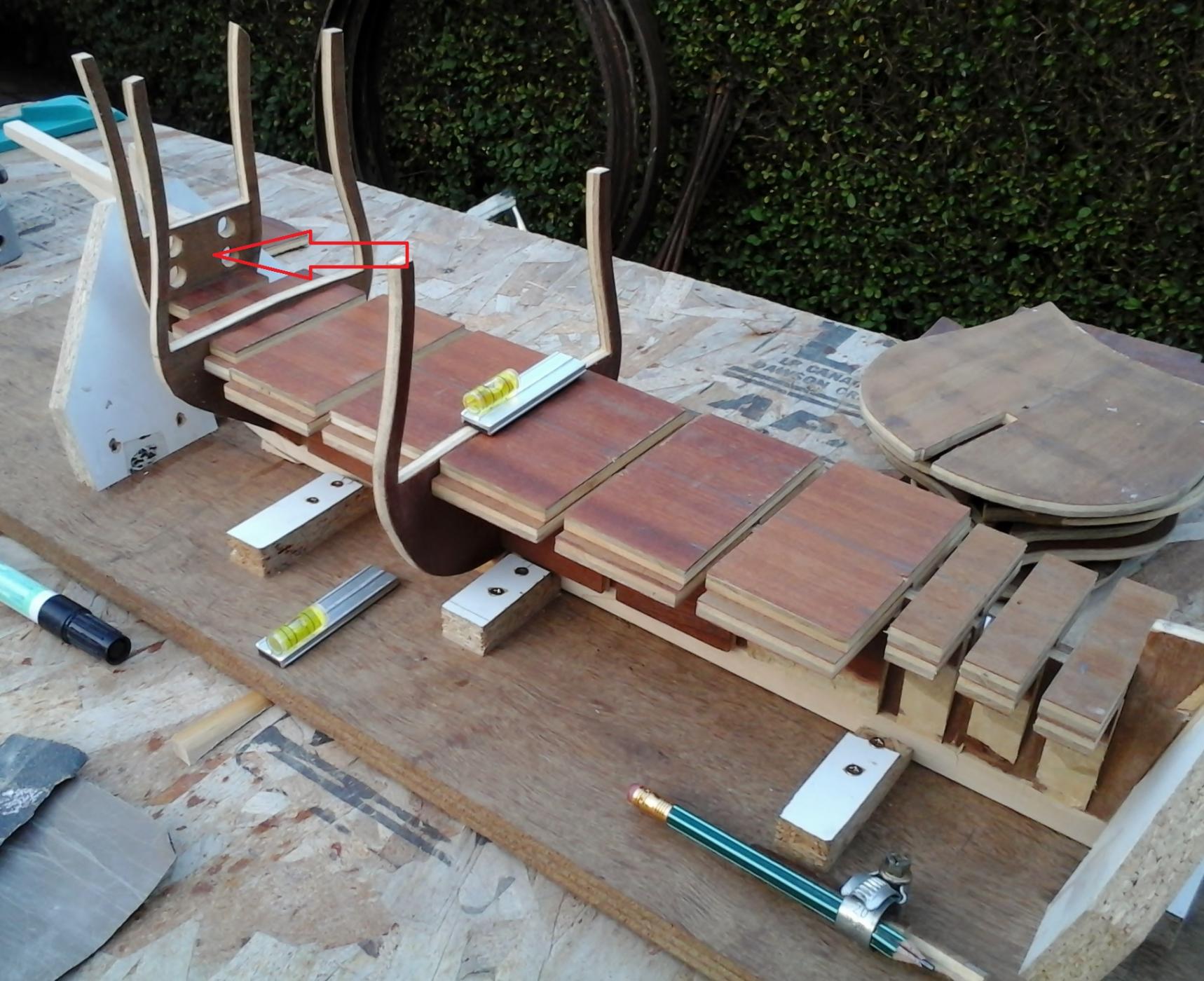
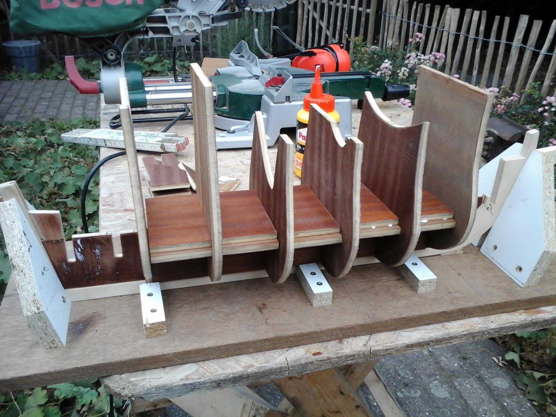
A few frames also had to be adjusted.
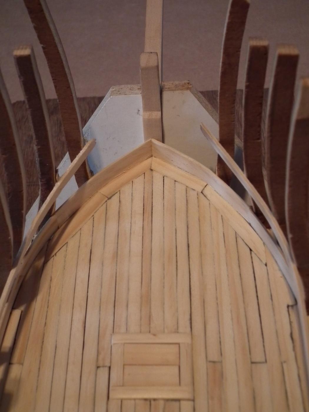
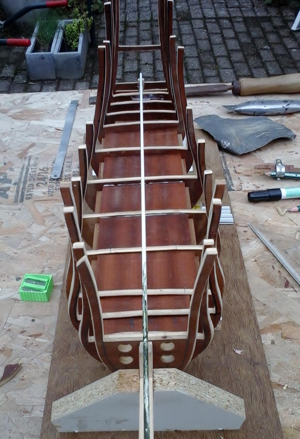
One side is filled up, and can be sanded.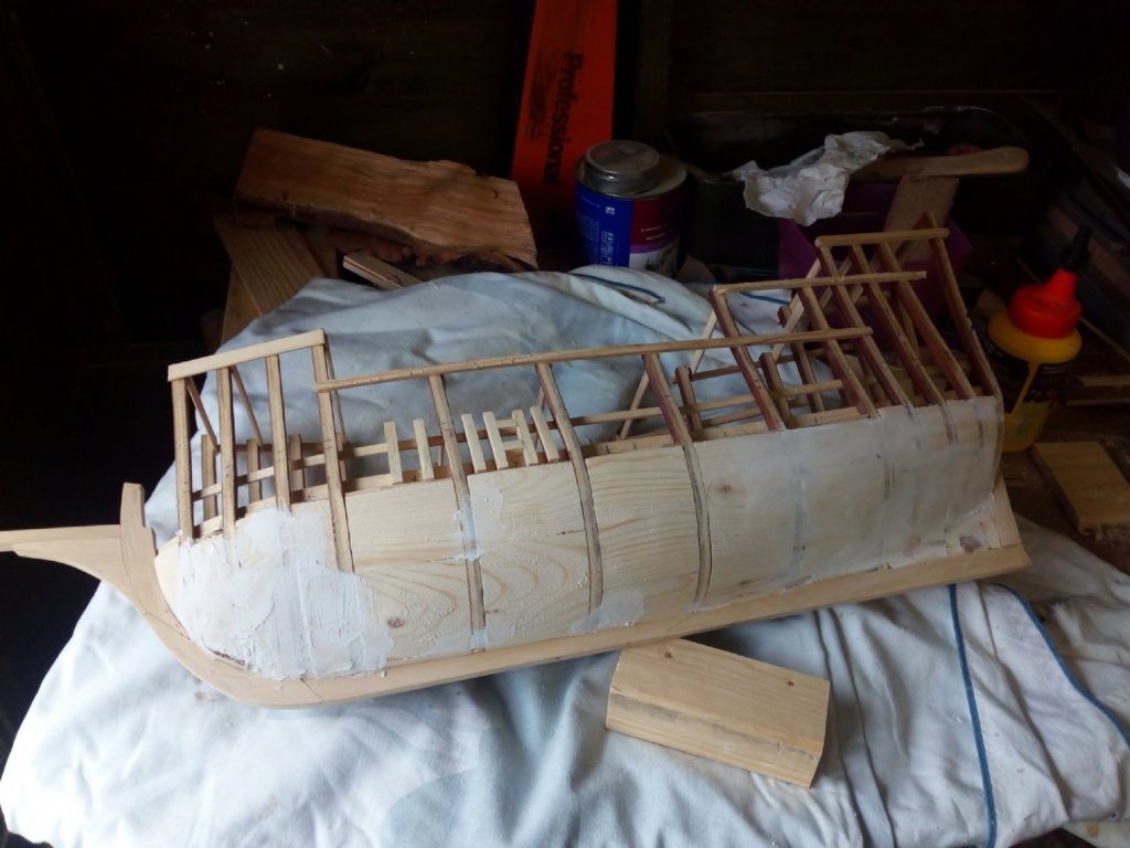
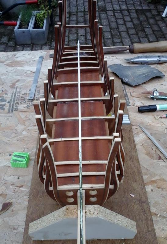
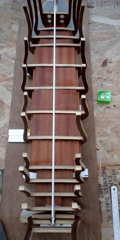
One side is sanded
I used this machine to sand the rough shape
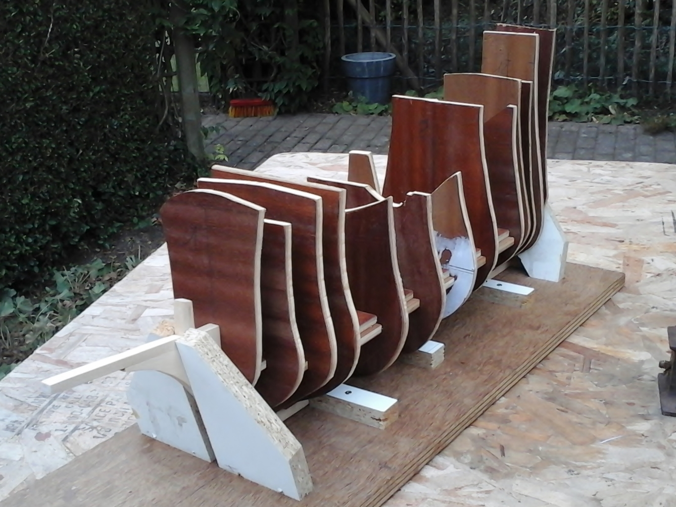
Some test planking is attached (looks ok)
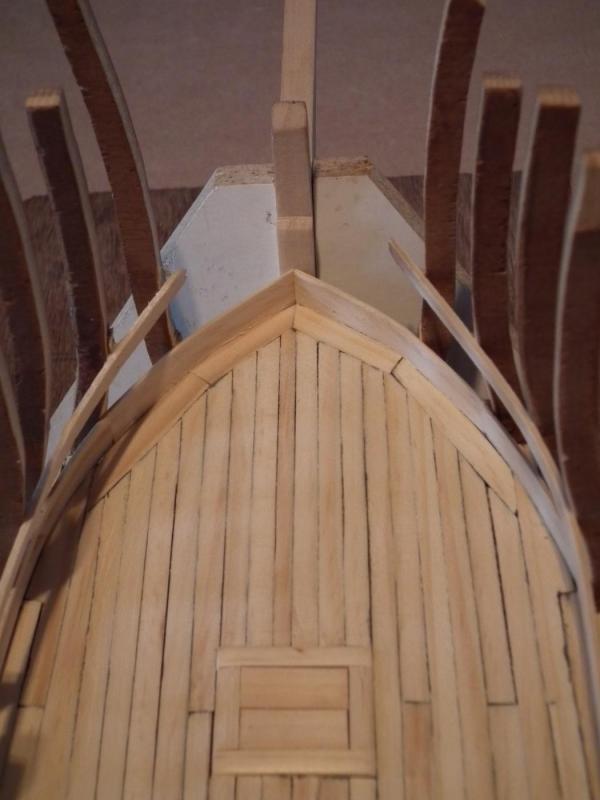
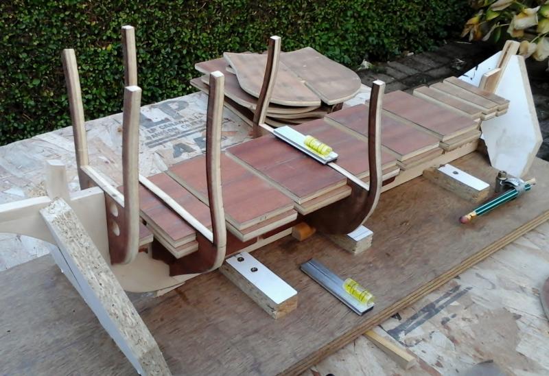
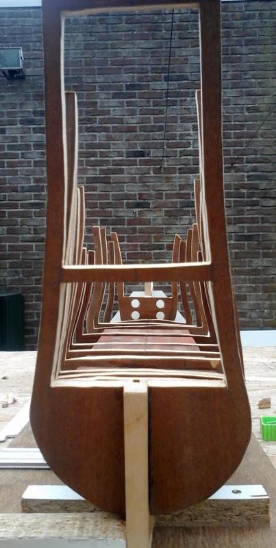
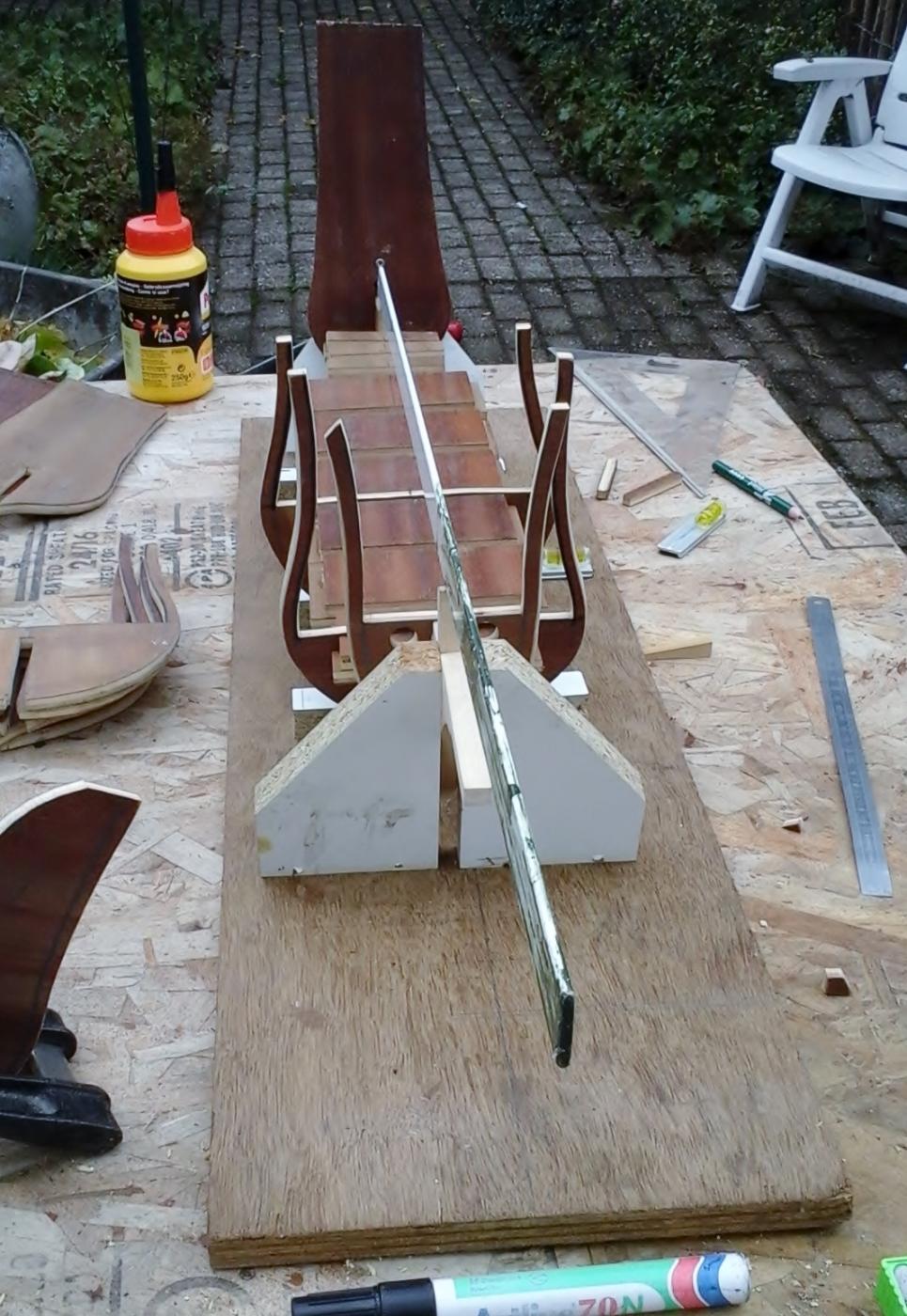
The frame of the stern has been modified and should now have better shape (thanks druxey).
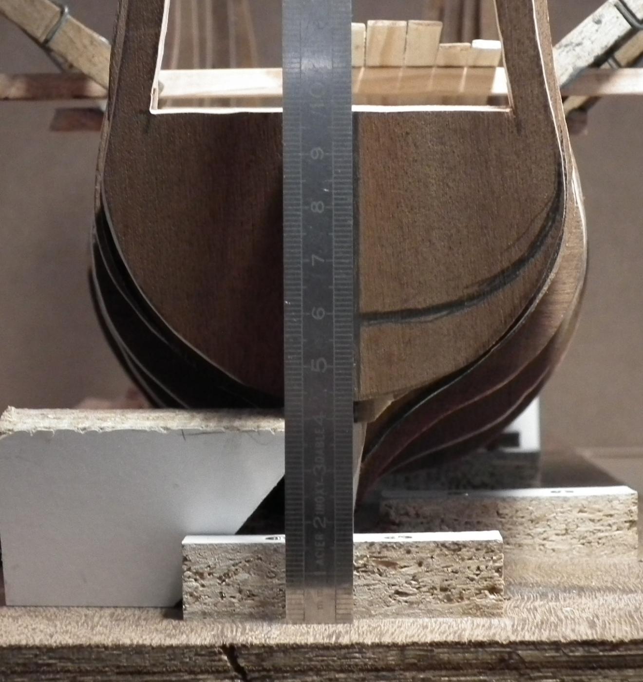
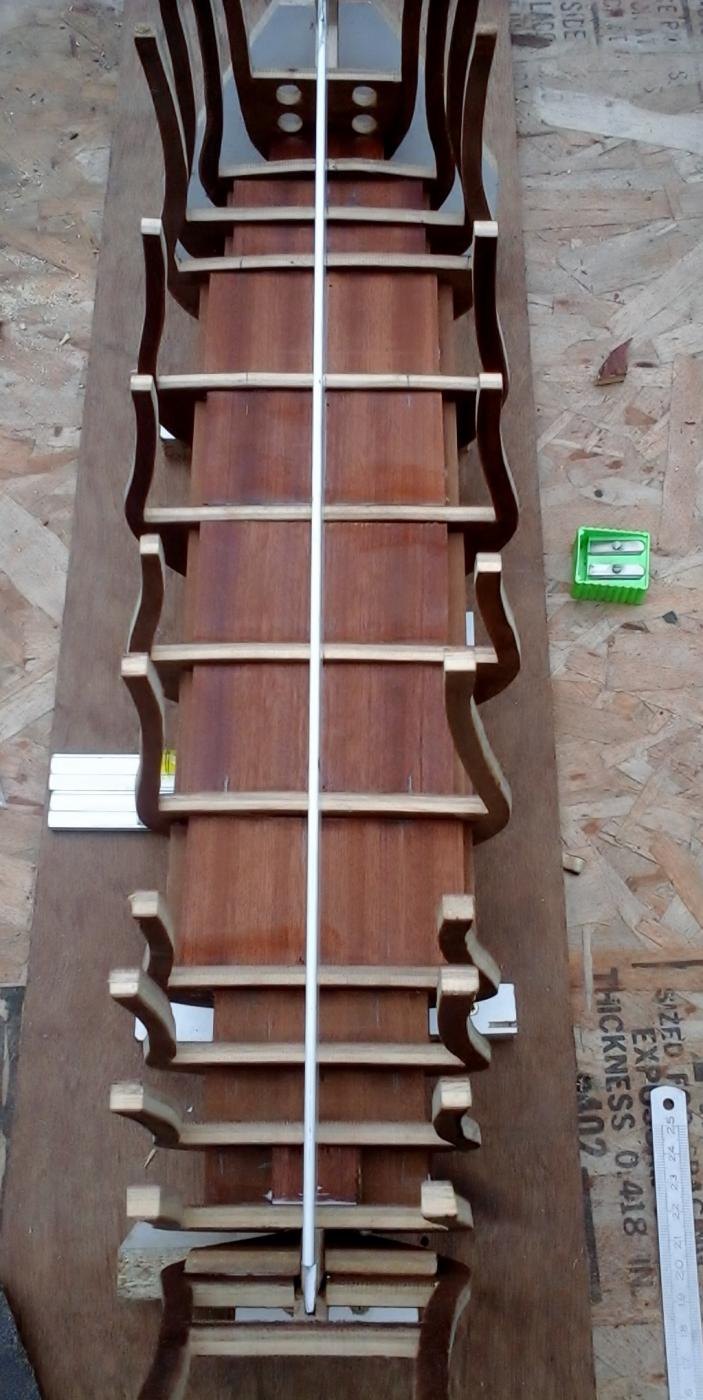
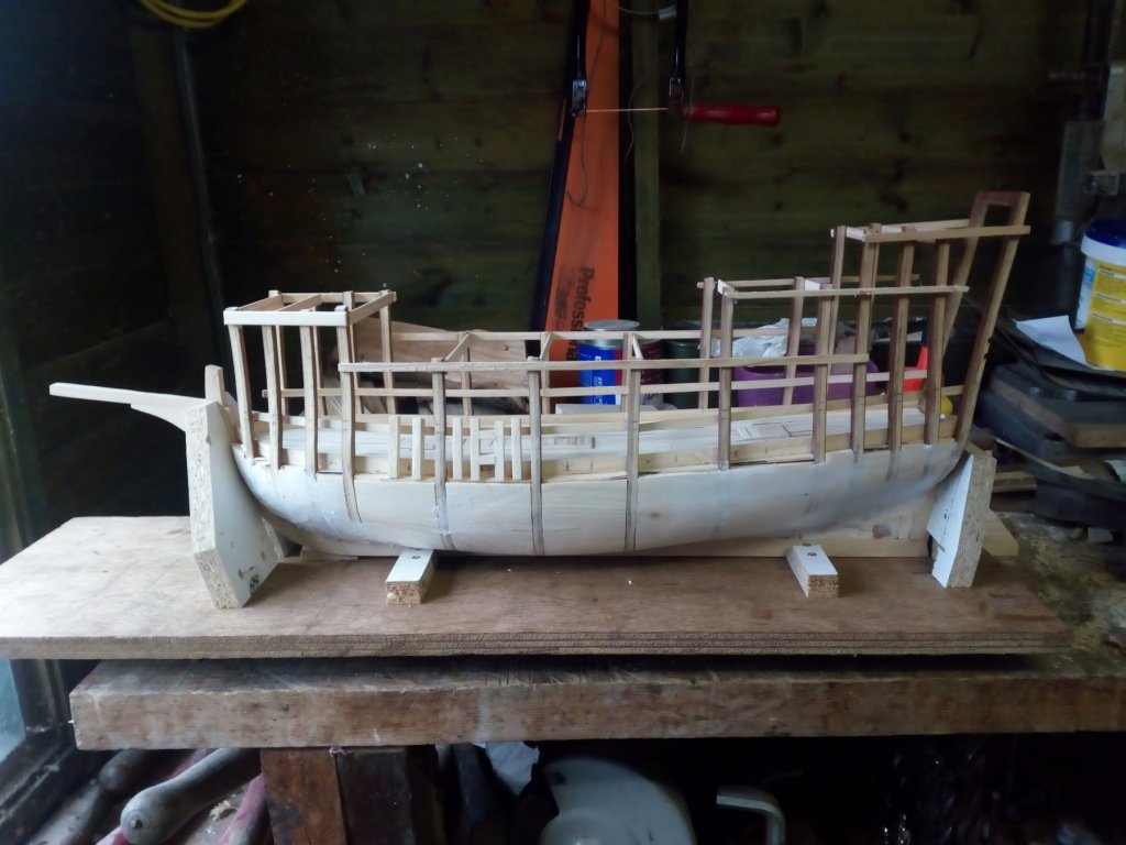
One side is done and seems to have the proper shape below the waterline
One side to go.
Ps,
I had picture uploade problems, see :
http://modelshipworld.com/index.php?/topic/15445-images-size-fixed-at-12-px/
Groetjes
Greetings