


Heronguy
-
Posts
863 -
Joined
-
Last visited
Content Type
Profiles
Forums
Gallery
Events
Posts posted by Heronguy
-
-
Good news, bad news and good news.
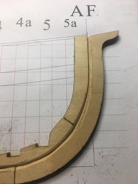
Good news - The acetone soaking freed up bulkhead U from the CA glue. I was able to use the rubber mallet "coaxer" to reset the bulkhead to a better position.
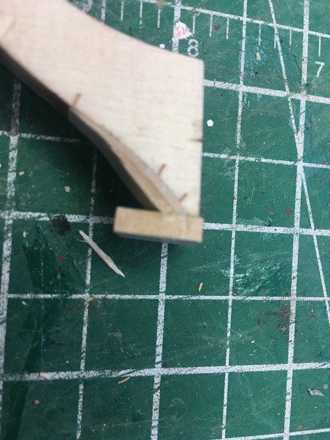
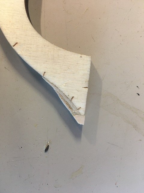
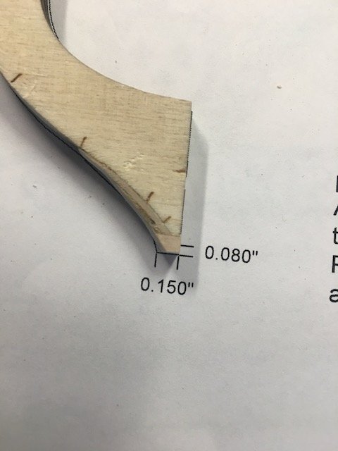
Bad news - The coaxing (alright - hammering!) that moved the bulkhead also caused the stem to break off (pretty cleanly along the rabbet strip)
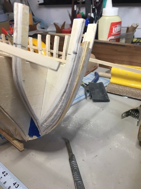
Good news - With the stem temporarily removed it was a fine time to improve the fairing of the bow formers since it was much easier to get good angles on it. (if I were to do it again I would consider whether the stem could be left off the hull until the fairing was complete).
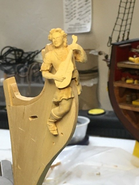
Furthermore since Jack's carvings had arrived I had a chance to check the fit. I needed a fair bit of additional sanding to get the figurehead to seat properly. It was much easier to accomplish with the stem separate from the hull!
Definitely the mis-aligned bulkhead turned out to be a silver lining problem.
- Wacom, FrankWouts, Edwardkenway and 9 others
-
 12
12
-
2 hours ago, VTHokiEE said:
One of the mistakes in my build was that my frames didn’t smoothly transition into the rabbet. I think I see some areas where this could occur to you as well (Frame A and Frame 4). You may want to consider building out the lower area of those frames to make the rabbet transition smooth.
I think you are quite right. Some refinements are called for!
-
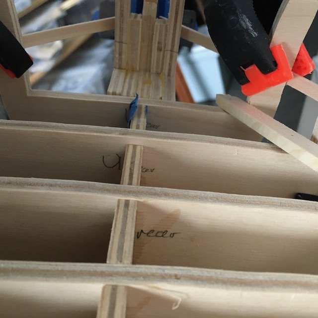
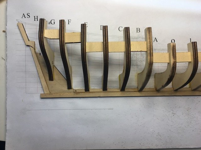
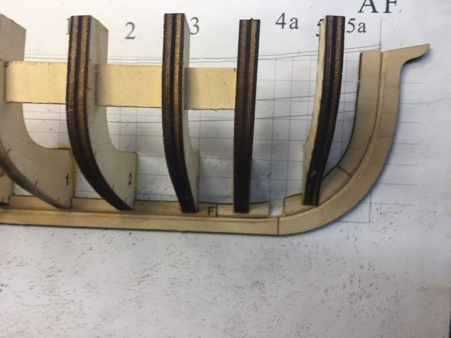
I made a couple of errors - hopefully recovered.
Here's the current state.
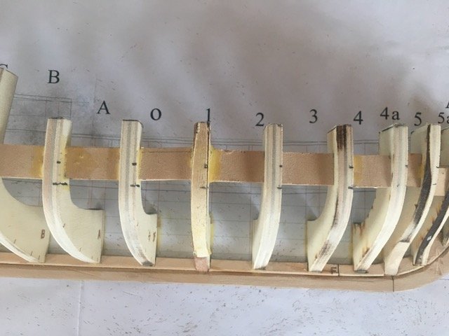
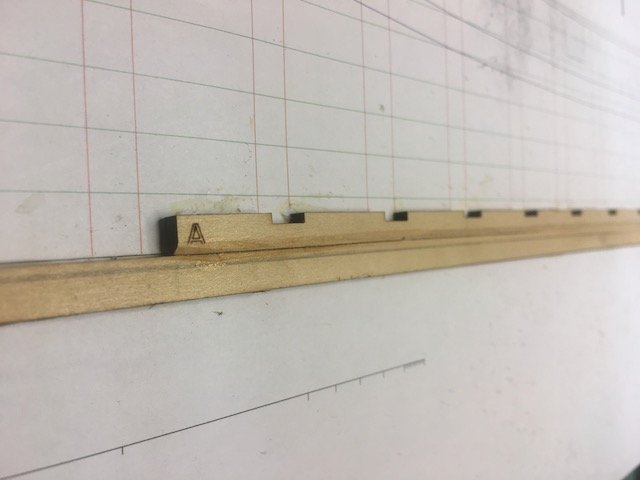
I've had to do some shims on frame 1
and on G1
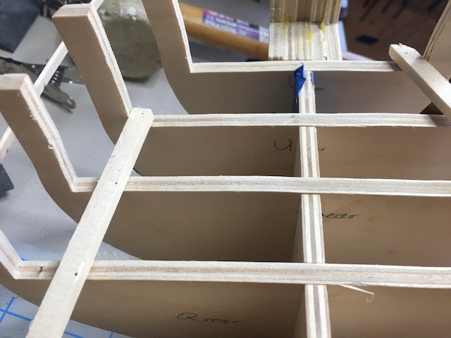
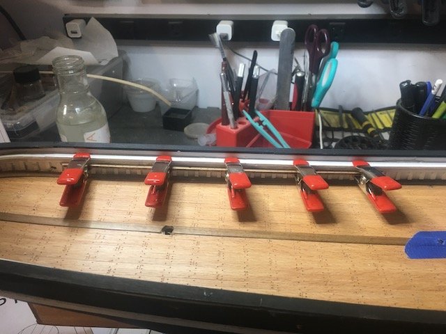
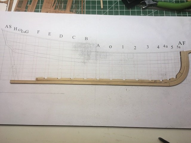
I didn't place the frame separators in convenient locations to allow the engineers square to mark the upper and lower positions of the wale. Thus the positioning is a bit crude. I guess I'll find out if that creates problems in the planking!!! I read ahead but didn't realize that the access from the plan marked wale would be blocked by the spacers. I see from Toni's pics that she located her spacers nearer to the tops of the frames.
I used dividers to mark the top of the wales where I could only use the square to mark the bottom position.
-
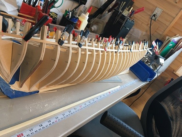
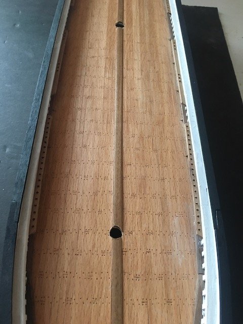
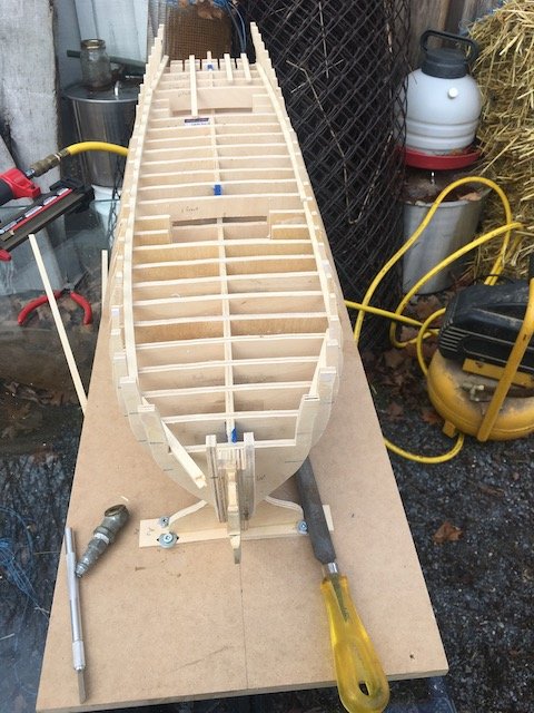
Although I'm not getting much time in the shipyard I have been slowly pushing on. Much of the fairing is done to my standards so I will probably do some more to try to improve my standards a bit!
I have run into a "challenge" however. While fairing the hull was upside down. I had noticed that bulkhead U needed a bit of shimming up and had started to apply some strips to build it up a bit. When I right-sided the hull to start running the battens along the top of the gunports I finally noticed that bulkhead U was not fully seated in the BF. It wasn't properly glued down. It seemed like a s simple fix so out with the rubber mallet to coax it down a bit. It looked pretty good so I ran some CA into the seams. Problem should have been solved. Somehow - I still haven't quite decided when this fix went off the rails but - the bulkhead, now well glued, slipped upward again.
There is about 1-2 mm slip. I am now contemplating which of 2 courses of action to take 1- try to soak the joint with acetone to free the bulkhead again - reset if, and make sure it doesn't slip before the glue sets or 2- leave it alone, fair the hull with there shims in place and there deal with the deck level "bump" . I don't like 2 very much because of the amount to sanding required on t his annoyingly tough plywood as well as the camber of the deck to get right especially near the edges where the bulkheads interfere with the sanding process. So I'll try 1 and if I can't get the joint free then I'll try plan 2. Sigh.
Before
After
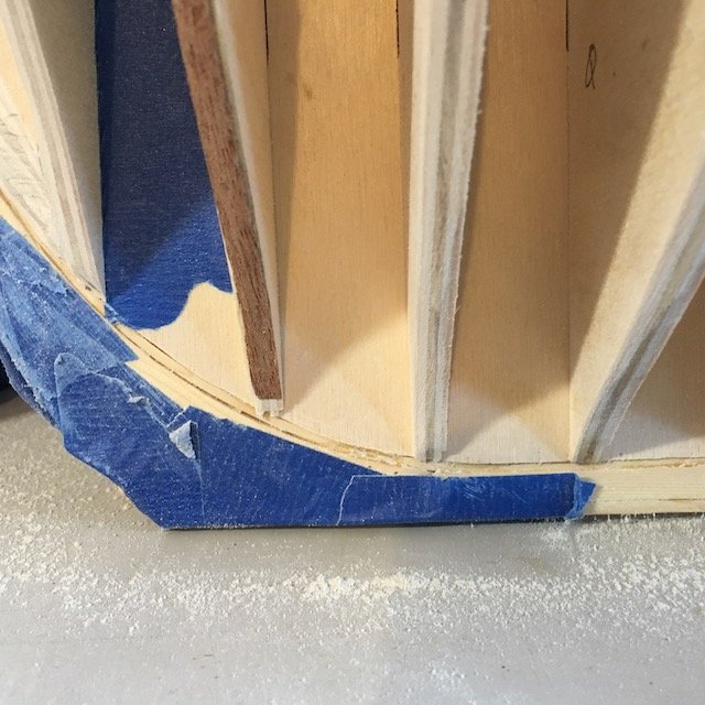
Deck level
- Rustyj, rafine, GrandpaPhil and 5 others
-
8
-
I’ll look forward to sharing experiences on this project. Slow is my mantra as well. It should be fun.
-
Thanks Toni. I hoped fairing would correct any minor positioning. I glued H to the plan as well as the deadwood and to frame Gb for good measure. Filler is now in place between Ga and Gb. I've started fairing.
-
I found the final frame (H) was harder to position since it has very little glueing surface.
I decided to attach frame Gb 1st then use it to support frame H.
I'm hoping the position of the frame is close enough to correct. I suppose the planking will prove that one way or another!
-
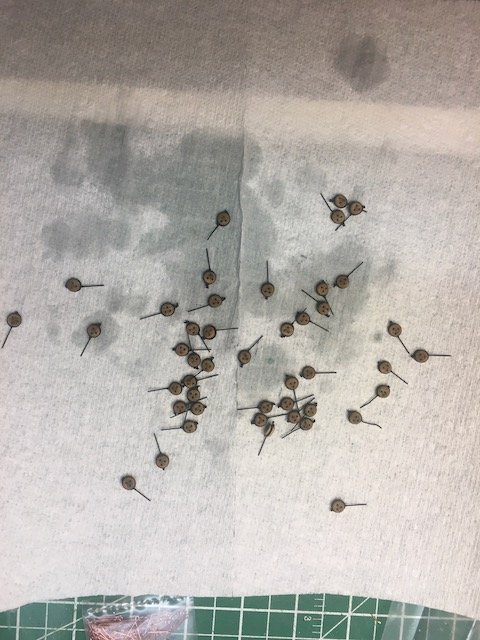
The lower deadeyes are installed.
Each was wired with a small eyebolt that attaches it to the main rail.
- GrandpaPhil, robdurant, rafine and 4 others
-
7
-
On 12/12/2019 at 10:07 AM, Jorge Diaz O said:
Hola muy buen trabajo la motosaw de Dremel, ¿cómo se comporta con la vibración, es práctica?
Yes the motosaw works well - there isn’t excessive vibration. I am quite pleased with it - value for money.
Sí, la motosaw funciona bien, no hay vibración excesiva. Estoy bastante satisfecho con esto: relación calidad-precio.- FrankWouts and Jorge Diaz O
-
2
-
-
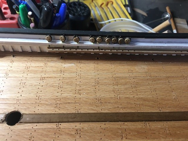
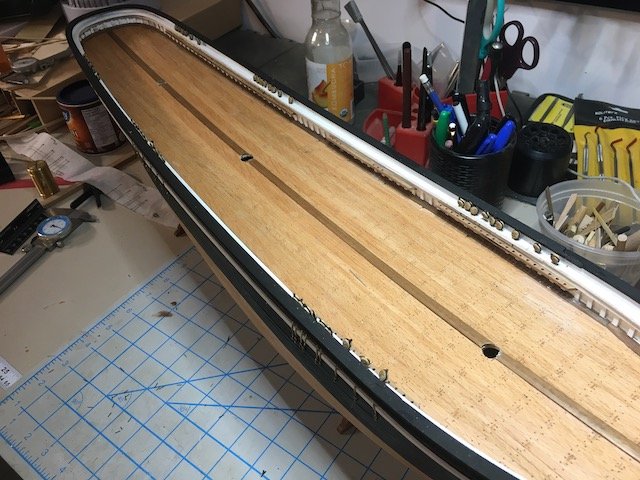
The deadeyes are attached to the eyebolts with some wire and the unit then glued into holes drilled in the mainrail.
Then onward to coppering the hull!
- Matt D and popeye the sailor
-
2
-
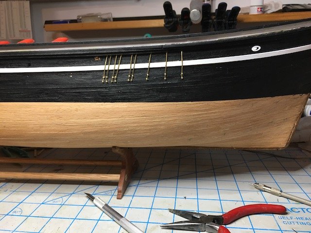
Current task is to install the chainplates. On this kit the chainplates are simulated by PE strips attached to the exterior hull but not all the way through the rails. Eyebolts will be inserted on the rails to complete the appearance of chainplates.
Copying the position of the chainplates from the plans made it straightforward to position the PE strips.
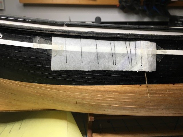
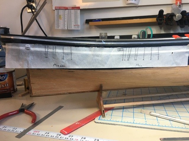
The foremast chainplates
-
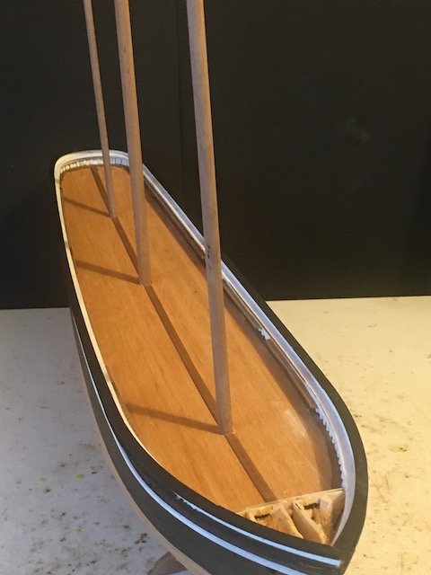
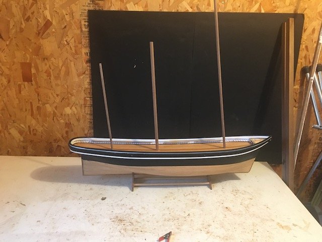
I attached the pinrails and finished drilling holes in the deck for the masts.
- popeye the sailor, coxswain, rafine and 1 other
-
4
-
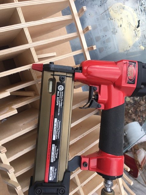
I thought that if I could stiffen the bulkheads without putting in spacers that I could get on with the fairing of the hull. I decided to try out using a pin nailer to attach scrap strips along the edges of the deck level on the bulkheads.
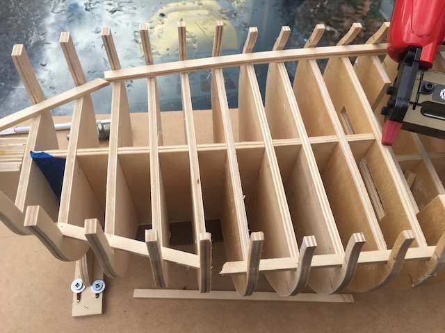
They are quite easy to pry up after I'm finished. They seem to have provided the effect I was looking for so I have started fairing the hull.
-
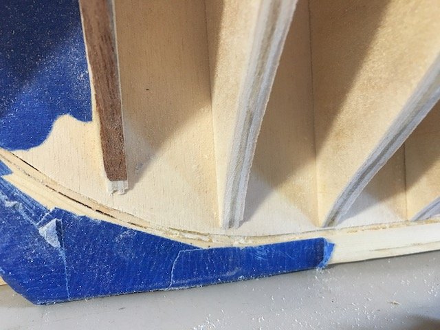
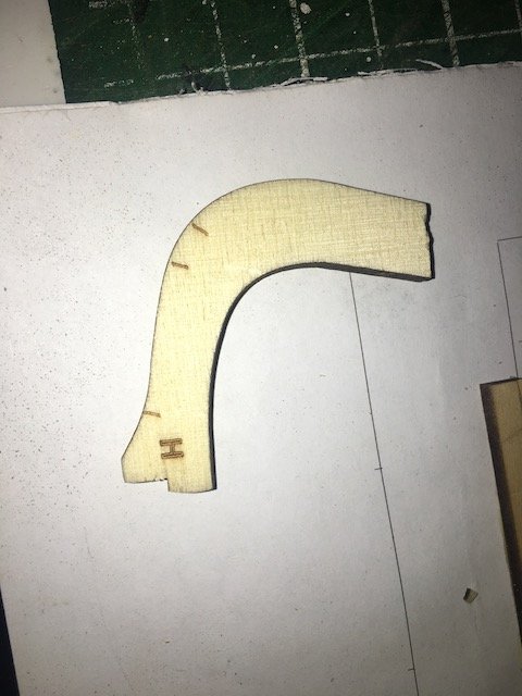
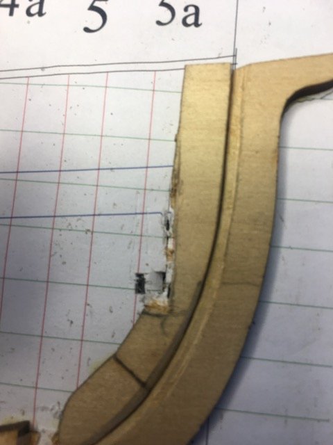
The errata sheet included with the kit indicates the correction to bulkhead 4a.
I used a a couple of strips off the basswood planking sheets to build up material on the curved section. Then glued a small piece of scrap from the keel sheet to the bottom.
Off to the sander to shape it and reduce to template dimensions.
Final adjustments will be accomplished during fairing the hull.
- Blue Pilot, Matrim, GrandpaPhil and 3 others
-
6
-
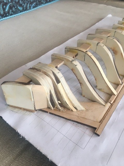
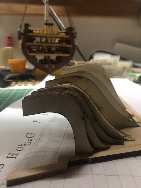
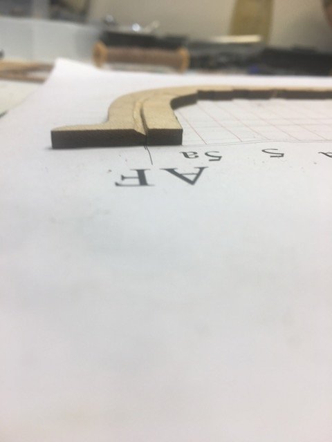
The hull is shaping up
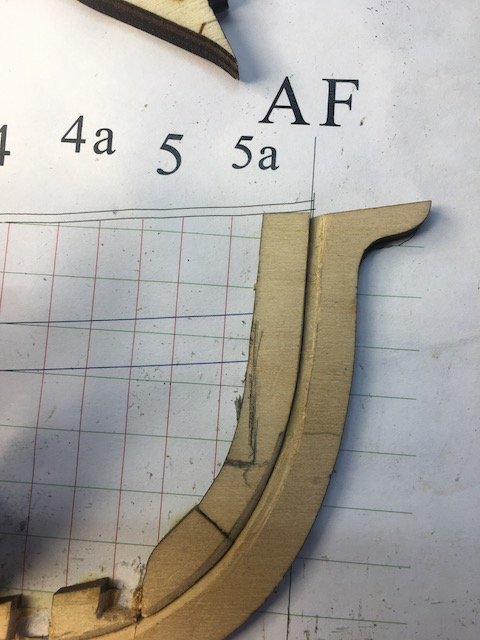
At the bow the slots are prepared for the bulkheads. I used images from Toni's log to get the depth of the slots for bulkheads 5 and 5a. (5 is just a press fit in this photo). Cutting the stemson for 5a with blades and micro chisels was easy enough but did damage the foam core build board. Of course it will all be out of site soon.
- VTHokiEE, Ryland Craze, Canute and 2 others
-
5
-
10 hours ago, Blue Pilot said:
I think I will follow along with you. My kit is in the mail. Looks good so far.
I noticed your interest on Toni's build log and thought if there might be a group project going I should start my own build log. So there will be at least 2 of us! Arre you going to start right away?
-
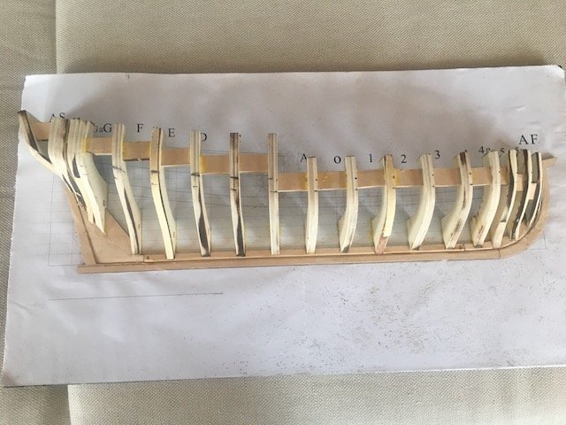
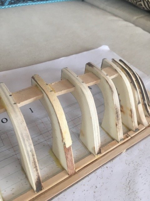
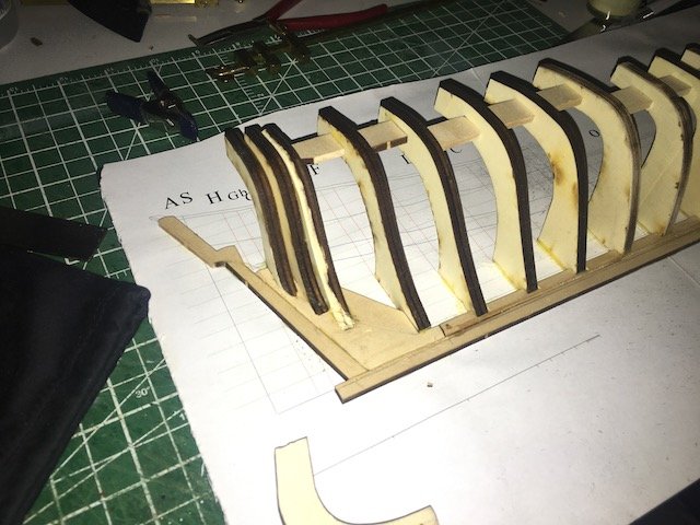
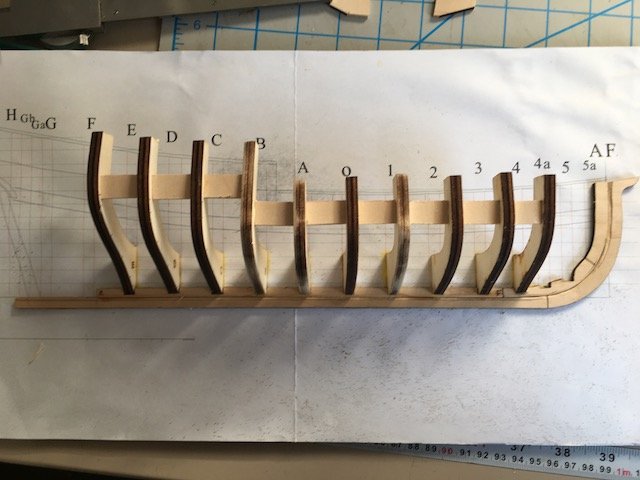
Raising the ribs
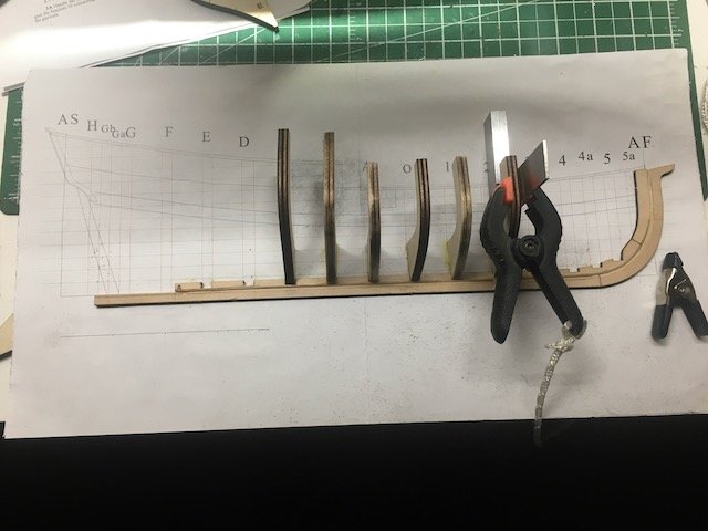
And adding some spacers (the spacers in my kit were not actually squared - very slightly trapezoidal - so I cut new one from the waste part of the sheets)
- JeffT, tlevine, Edwardkenway and 6 others
-
9
-
-
I've added a build log.
- Canute, tlevine, Blue Pilot and 1 other
-
4
-
I'm joining the fun of this "learning exercise".
Started:
Using a foam core building board. Rabbet cut. (Without much thought I started cutting the rabbet on both sides of the keelson before I remembered that this was a half hull - oops)
-
-
-
Hi Derek
Good to see you back at the bench. You'll get lots of use out of the saw with this build!
18th-Century Merchantman Half-Hull Planking Kit by VTHokiEE - FINISHED - NRG - 1:48
in - Kit build logs for subjects built from 1751 - 1800
Posted
I think it is looking good. If I’m able to generate a bit of firewood along with planking the model then I’ll be ahead of the game😁. I suppose you you don’t need as much kindling in FL
You’re doing a good job and leading the way! Perhaps we’ll get a group build soon?